EP3479751A1 - Dispositif de charge pour appareil électroménager et appareil électroménager - Google Patents
Dispositif de charge pour appareil électroménager et appareil électroménager Download PDFInfo
- Publication number
- EP3479751A1 EP3479751A1 EP18200038.0A EP18200038A EP3479751A1 EP 3479751 A1 EP3479751 A1 EP 3479751A1 EP 18200038 A EP18200038 A EP 18200038A EP 3479751 A1 EP3479751 A1 EP 3479751A1
- Authority
- EP
- European Patent Office
- Prior art keywords
- contact points
- charging
- interface
- household appliance
- energy storage
- Prior art date
- Legal status (The legal status is an assumption and is not a legal conclusion. Google has not performed a legal analysis and makes no representation as to the accuracy of the status listed.)
- Granted
Links
Images




Classifications
-
- A—HUMAN NECESSITIES
- A47—FURNITURE; DOMESTIC ARTICLES OR APPLIANCES; COFFEE MILLS; SPICE MILLS; SUCTION CLEANERS IN GENERAL
- A47L—DOMESTIC WASHING OR CLEANING; SUCTION CLEANERS IN GENERAL
- A47L9/00—Details or accessories of suction cleaners, e.g. mechanical means for controlling the suction or for effecting pulsating action; Storing devices specially adapted to suction cleaners or parts thereof; Carrying-vehicles specially adapted for suction cleaners
- A47L9/28—Installation of the electric equipment, e.g. adaptation or attachment to the suction cleaner; Controlling suction cleaners by electric means
- A47L9/2868—Arrangements for power supply of vacuum cleaners or the accessories thereof
- A47L9/2873—Docking units or charging stations
-
- A—HUMAN NECESSITIES
- A47—FURNITURE; DOMESTIC ARTICLES OR APPLIANCES; COFFEE MILLS; SPICE MILLS; SUCTION CLEANERS IN GENERAL
- A47L—DOMESTIC WASHING OR CLEANING; SUCTION CLEANERS IN GENERAL
- A47L2201/00—Robotic cleaning machines, i.e. with automatic control of the travelling movement or the cleaning operation
- A47L2201/02—Docking stations; Docking operations
- A47L2201/022—Recharging of batteries
Definitions
- the invention relates to a charging device for charging an electrical energy storage unit of a mobile household appliance. Moreover, the invention relates to a household appliance with an electrical energy storage unit for charging with such a charging device.
- Household appliances in the form of vacuum cleaners are used in households and businesses for cleaning surfaces such as textile floor coverings and smooth floors.
- a floor nozzle of the vacuum cleaner is continuously pushed back and forth on a floor surface for dust absorption.
- the floor surface may be covered by a textile floor covering such as a carpet or carpet or by a hard floor such. As a wood parquet, laminate or PVC flooring are formed.
- Such vacuum cleaners with a power supply via accumulators as an energy storage unit must be charged regularly.
- different charging concepts are known.
- Device or battery charging cradles and external or internal power supplies are used.
- the user In order to make it possible to charge the electrical energy storage unit in the mobile household appliance, the user usually has to make numerous manipulations and possibly lift them with difficulty. What makes the operation of the household appliance for physically restricted users impossible.
- the DE 198 57 685 A1 describes a battery sucker with wall bracket.
- the invention thus presents the problem of providing an improved charging device and an improved household appliance.
- the charging of the electrical energy storage unit in a mobile household appliance should be simplified.
- a charging device having the features of patent claim 1 and a household appliance according to claim 13. Characterized in that the charging device comprises a housing, wherein the housing defines a direction of travel, in which the mobile household appliance can start from two opposite sides for charging the electrical energy storage unit on a roadway formed by the housing, a simple possibility is given via an electrical interface to contact a for charging the electrical energy storage unit ascended to the charger household appliance. This can be achieved that a household appliance such a possibly heavy and / or cumbersome vacuum cleaner for charging an electrical energy storage unit of the vacuum cleaner does not need to be raised.
- the design of the housing which forms a roadway drivable from two sides, makes it easier to contact the charging device with a driven-up household appliance, since two possibilities are defined by the housing in which the household appliance can charge the charging device for charging the electrical energy storage unit , This makes an intuitive use of the charging device and the household appliance possible. The acceptance can be increased due to the intuitive, simple operation even with less technical users.
- the household appliance designed as a vacuum cleaner may have a fan for generating a negative pressure, through which a floor nozzle guided over a floor surface to be cleaned receives dust and dirt from the floor surface.
- the floor nozzle is moved back and forth by the user by means of push and pull movements in the machine direction.
- the floor nozzle slides over the floor surface to be cleaned.
- the user can handle for example a connected to the suction pipe handle of the vacuum cleaner.
- the suction mouth is elongated and extends substantially transversely to the machining direction.
- elongated means that the preferably substantially rectangular suction mouth has a greater length transversely to the machining direction than the width in the machining direction.
- the suction mouth is preferably between 20 and 30 cm across the processing direction long.
- the floor nozzle can also be arranged on a self-propelled vacuum cleaner, in particular suction robot. In such a trained household appliance, the processing direction of the floor nozzle corresponds to the direction of travel of the self-propelled vacuum cleaner.
- a vacuum cleaner housing of the vacuum cleaner may have a dust receiving chamber in which the dust received via the floor nozzle can be collected, for example, in a dust bag.
- the interface has a plurality of contact points.
- the contact points of the interface it is easily possible to a for the process of charging on the loading device driven up home appliance to contact. This makes it possible to produce a reliable electrical connection between the charging device and the household appliance.
- the interface comprises two contact points, wherein the contact points are positioned from both opposite sides of symmetrical to the middle of the roadway.
- the symmetrical arrangement of the contact points to the center of the road allows a reliable contacting of a for charging the energy storage unit ascended to the charging device home appliance.
- the household appliance can drive from two opposite sides on the road formed by the housing of the loader and reliable contact can be made. This makes the operation of the household appliance and the charging device easy.
- the interface comprises an electrical component for polarity of the contact points.
- the interface provided with two contact points has an electrical component with which the polarity of the contact points can be adjusted or changed ,
- the adaptation of the polarity of the contact points takes place in this case depending on the side from which the household appliance is driven onto the road to charge the energy storage unit.
- the interface comprises three contact points, wherein a contact point is arranged from both opposite sides in the middle of the roadway and the other two contact points are positioned from two opposite sides of symmetrical to the middle of the roadway.
- the interface has three contact points in a particularly simple embodiment.
- the centrally located contact point makes contact with the household appliance regardless of which of the two opposite sides it has ascended to charge the energy storage unit onto the charging device.
- the out-of-center contact points are used depending on from which of the opposite sides the household appliance is charged for charging the energy storage unit on the charger for contacting.
- the polarity of the symmetrically positioned to the middle of the roadway contact points is the same.
- the centrally arranged contact point forms the negative or positive pole, wherein the out-of-center contact points in each case form the other pole.
- the interface comprises four contact points, wherein the contact points are positioned in pairs from both opposite sides of symmetrical to the middle of the roadway.
- the pairwise arrangement of the contact points symmetrical to the center of the road makes the design of the household appliance flexible, since the paired arrangement makes a flexible arrangement of contact points of an interface on the household appliance possible.
- the construction of the household appliance can be changed more flexibly and also different models and model series of the mobile home appliance can be provided with differently arranged contact points, which can be contacted via the paired contact points for charging the energy storage unit by the charging device.
- the symmetrical arrangement of the pairs positioned contact points allows the contacting of the household appliance for charging the electrical energy storage unit regardless of which of the two opposite sides of the household appliance is driven onto the road formed by the housing. This makes the operation of the household appliance flexible and allows constructive adjustments across model series.
- the proposed charging device can be used for different model series of the household appliance without constructive changes to the charging device would be necessary. This results in a universally applicable charging device.
- the pairs of positioned contact points are arranged one behind the other in the direction of travel, wherein the polarity of the contact points is the same diagonal to the middle of the roadway.
- the contact points of the interface are arranged on the road.
- the arrangement of the contact points on the roadway of the charging device allows the driven-up household appliance simply to contact at the bottom.
- contact points can be arranged on the bottom, so that the contact points are not visible in normal operation and the optical image of the household appliance is not affected by the contact points.
- a preferred embodiment provides that the contact points of the interface are resiliently mounted. About resilient contact points a secure contact of the household appliance for charging the electrical energy storage device on the charger can be easily achieved.
- the housing forms at least one positioning device, which is designed to position the household appliance which has been brought onto the loading device with respect to the interface.
- the position of the household appliance in the direction of travel on the road can be defined.
- the household appliance relative to the interface of the charger can be reliably positioned so that the contacting of the driven home appliance through the interface is exactly possible.
- the positioning device is designed as a curvature, wherein the curvature is adapted to receive at least one moving element of the household appliance.
- a movement element can be designed as a wheel or skid and allow the locomotion of the mobile household appliance on the floor surface. With the specified position of the recorded movement element on the household appliance, the household appliance can be reliably positioned by the positioning device relative to the interface of the charging device.
- the subject matter of the invention is a household appliance with an electrical energy storage unit and an interface for charging the electrical energy storage unit, wherein the interface is designed to contact a charging device already described in greater detail below for charging the electrical energy storage unit.
- the interface has at least two contact points, which are adapted to be contacted by contact points of the charging device side interface for charging the electrical energy storage unit on the charging device. With two contact points, it is very easy to establish an electrical connection for charging the energy storage unit via the interface.
- the mobile household appliance is preferably a floor care appliance or vacuum cleaner for cleaning and care of floor surfaces with a blower for generating a negative pressure for receiving dirt by means of an air flow and a separation system for cleaning the absorbed air from the dirt.
- FIG. 1 shows a charging device 1 according to the invention with the invention on the charging device 1 driven up household appliance 50.
- the charging device 1 is provided for charging an electrical energy storage unit of the mobile domestic appliance 50 and connected to the mains.
- the housing 2 of the charging device 1 defines a direction of travel 3, indicated as a double arrow, in which the mobile domestic appliance 50 can ascend onto the charging device 1 for charging the energy storage unit.
- the housing 2 of the charging device 1 forms for this purpose a roadway 6, which from two opposite sides 4, 5 (FIG. Fig. 3 ) can be traveled from the household appliance 50.
- a self-propelled household appliance can thus also from two sides 4, 5 ( Fig. 3 ) ascend to the lane 6 of the loading device 1. In order to get easier on the lane 6 of the charging device 1, can then be to this, formed by the housing 2, ramps, which extend to the bottom surface.
- the charging device 1 has an interface 7, which is designed to charge the powered household appliance 50 for charging the electrical energy storage unit.
- the household appliance 50 shown in the exemplary embodiment is a so-called canister vacuum cleaner, which can be pulled over the floor surface onto the loading device 1 via movement elements 52 designed as wheels.
- a bottom nozzle, not shown here is usually connected via a connecting piece with a preferably telescopically designed suction tube. Furthermore, the floor nozzle has its own from the vacuum cleaner housing 55 independent housing. Not shown telescopic suction pipe usually passes into a handle, not shown, to which a suction hose is connected, which is connected to the vacuum cleaner housing 55 via the hose connection 56 shown. A blower (not shown) of the vacuum cleaner 50 integrated with the vacuum cleaner housing 55 is operated with power from an energy storage unit, not shown, to generate a negative pressure.
- dirt or dirt are taken up by the floor surface to be cleaned by a stream of air through a suction mouth of the floor nozzle and transported via the suction pipe and the suction hose into the housing 55 of the vacuum cleaner 50.
- a separation system not shown, which may be formed as a dust bag.
- This separation system is usually located in a dust chamber 50 formed in the housing 55 of the vacuum cleaner.
- a negative pressure is created by the blower, through which an air flow is generated, which is freed of dirt and dirt in the separation system and is led out of the vacuum cleaner 50 via an exhaust air opening.
- this has a treadle, not shown.
- This treadle usually includes switches that are large enough for a user to operate with his foot.
- On the handle is also regularly a manual circuit, with the functions of the vacuum cleaner 50 can be activated.
- the vacuum cleaner can be switched on and off via the manual circuit and power levels of the fan (not shown) can be selected.
- FIG. 2 shows the charging device 1 and the household appliance 50 in a front view from the direction of travel 3 ( Fig. 1 ).
- the household appliance 50 is shown driven up to the charging device 1, so that the energy storage unit of the household appliance 50 can be charged by the charging device 1.
- the roadway 6 is formed by a U-shaped portion of the housing 2 of the charging device 1.
- the middle 10 of this formed roadway 6 is indicated by a dashed line 10.
- the interface 7 for contacting the household appliance 50 to the charging device 1 has a plurality of contact points 8, 9. Two of these contact points 8, 9 are positioned symmetrically to the roadway center 10. This symmetrical arrangement is also the same from the opposite side of the lane 6.
- the household appliance 50 in the opposite direction 3 ( Fig. 3 and 4 ) Contact the illustrated contact points 8, 9 for charging the electrical energy storage.
- the interface 7 can comprise an electrical component for adapting the polarity at the contact points 8, 9.
- a sectional plane AA is drawn.
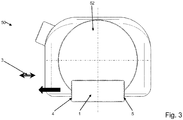
- FIG. 3 shows a loading device 1 in side view.
- the up to the charging of the electrical energy storage unit on the loading device 1 driven home appliance 50 can with the movement elements 52 in the direction of travel 3 from right to left on the from the housing 2 ( Fig. 2 ) formed roadway 6 ( Fig. 2 ) are moved or moved.
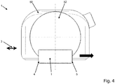
- FIG. 4 discloses the loading device 1 in the side view according to FIG. 3 ,
- the household appliance 50 which has been brought up onto the charging device 1 for charging the electrical energy storage unit can move with the movement elements 52 in the direction of travel 3 from left to right via the housing 2 (FIG. Fig. 2 ) formed roadway 6 ( Fig. 2 ) are moved or moved.
- the housing 2 of the charging device 1 defines a direction of travel 3, in which the mobile domestic appliance 50 can drive from two opposite sides 4, 5 for charging the electrical energy storage device on the roadway 6 formed by the housing 2 of the charging device 1.
- FIG. 5 shows a schematic sectional view according to the in FIG. 2 It can be seen that a plurality of contact points 8, 11 of the charging device-side interface 7 in the direction of travel 3 are arranged one behind the other on the carriageway 6.
- the contact points 8, 11 of the interface 7 are spring-mounted, which is indicated by the illustrated spring elements. This suspension ensures reliable contacting of the charging device 1 via the contact points 8, 11 with the household appliance 50.
- Home appliance side an interface 51 is provided which has two contact points 53, 54 for contacting with the contact points 8, 11 of the charging device 1. These household appliance-side contact points 53, 54 may be spring-mounted.
- the encirclement Z is a region marked in FIG. 6 is shown enlarged.
- FIG. 6 is an enlarged detail view of the sectional view according to FIG. 5 out.
- the sprung mounting of the contact points 8, 11 of the charging device-side interface 7 can be seen better.
- the on the charging device 1 for charging the electrical energy storage unit driven up household appliance 50 is contacted by the spring-mounted contact points 8, 11 at the bottom of the household appliance 50.
- the household appliance side, the designated contact points 53, 54 can be seen. These can also be designed to be spring-mounted.
- the FIG. 7 shows a loading device 1 in a perspective view. It can be seen that the roadway 6 is formed by the U-shaped portion of the housing 2 of the charging device 1. The middle 10 of this formed roadway 6 is indicated by a dashed line 10.
- the interface 7 for contacting the household appliance 50 (FIG. Fig. 1 to 6 ) on the loading device 1 has a plurality of contact points 8, 9, 11, 12.
- the contact points 8, 9, 11, 12 are positioned from both opposite sides 4, 5 from symmetrical to the roadway center 10 and arranged on the roadway 6.
- the contact points 8, 9, 11, 12 are spring-mounted.
- the four contact points 8, 9, 11, 12 are in pairs from both sides 4, 5 are positioned symmetrically to the middle of the lane 10.
- the left-hand contact points 8, 11 and the right-hand contact points 9, 12 each form a pair. These so positioned in pairs contact points 8, 11, 9, 12 are arranged one behind the other in the direction of travel 3.
- the polarity of the four electrical contact points 8, 9, 11, 12 is diagonal to the middle of the roadway 10 equal. This is indicated by the large plus and minus signs, which should indicate the polarity as an example.
- the household appliance 50 can start to charge the energy storage device from both opposite sides 4, 5 in the direction of travel 3 on the roadway 6 of the charging device 1 for charging the energy storage unit.
- the contact points 8, 9, 11, 12 are positioned symmetrically to the center of the roadway 10. This symmetrical arrangement is the same from the opposite sides 4, 5 of the lane 6.
- the household appliance 50 in the opposite direction 3 ( Fig. 3 and 4 ) Contact the illustrated contact points 8, 9, 11, 12 for charging the electrical energy storage.
- the housing 2 of the charging device 1 forms at least one positioning device 13, which positions the driven household appliance 50 on the charging device 1 with respect to the interface 7 of the charging device 1.
- the positioning device 13 is embedded as a curvature in the roadway 6, wherein the curvature 13, the movement element formed as a wheel 52 (FIG. Fig.
- the charging device can also be equipped with an interface for charging a floor nozzle provided with an energy storage unit.
Landscapes
- Engineering & Computer Science (AREA)
- Robotics (AREA)
- Mechanical Engineering (AREA)
- Charge And Discharge Circuits For Batteries Or The Like (AREA)
Applications Claiming Priority (1)
| Application Number | Priority Date | Filing Date | Title |
|---|---|---|---|
| DE102017125964.3A DE102017125964A1 (de) | 2017-11-07 | 2017-11-07 | Ladevorrichtung für Haushaltsgerät und Haushaltsgerät |
Publications (2)
| Publication Number | Publication Date |
|---|---|
| EP3479751A1 true EP3479751A1 (fr) | 2019-05-08 |
| EP3479751B1 EP3479751B1 (fr) | 2021-08-18 |
Family
ID=63840661
Family Applications (1)
| Application Number | Title | Priority Date | Filing Date |
|---|---|---|---|
| EP18200038.0A Active EP3479751B1 (fr) | 2017-11-07 | 2018-10-12 | Dispositif de charge pour appareil électroménager et appareil électroménager |
Country Status (2)
| Country | Link |
|---|---|
| EP (1) | EP3479751B1 (fr) |
| DE (1) | DE102017125964A1 (fr) |
Citations (4)
| Publication number | Priority date | Publication date | Assignee | Title |
|---|---|---|---|---|
| KR20100066134A (ko) * | 2008-12-09 | 2010-06-17 | 웅진코웨이주식회사 | 로봇 청소기 시스템 |
| DE202010005457U1 (de) * | 2009-10-16 | 2010-09-30 | MICRO-STAR INTERNATIONAL CO., LTD., Jung-He City | Elektronische Vorrichtung |
| EP2899832A1 (fr) * | 2012-08-02 | 2015-07-29 | Sumec Hardware & Tools Co. Ltd. | Système de station de charge de dispositif de travail automatique |
| EP3280026A1 (fr) * | 2016-08-03 | 2018-02-07 | Miele & Cie. KG | Dispositif de charge pour appareil domestique et procédé de chargement d'un appareil domestique |
Family Cites Families (5)
| Publication number | Priority date | Publication date | Assignee | Title |
|---|---|---|---|---|
| DE19857685A1 (de) | 1998-12-14 | 2000-06-15 | Dabelstein Lutz | Stiel-Besen mit integrierter Akku-Staubsaugeinrichtung |
| CN1143651C (zh) * | 2000-03-01 | 2004-03-31 | 松下电器产业株式会社 | 电动吸尘器 |
| DE10231388A1 (de) * | 2002-07-08 | 2004-02-05 | Alfred Kärcher Gmbh & Co. Kg | Bodenbearbeitungssystem |
| JP3905867B2 (ja) * | 2003-07-17 | 2007-04-18 | 東芝テック株式会社 | 充電式電気掃除機 |
| KR101615430B1 (ko) * | 2014-05-09 | 2016-04-25 | 엘지전자 주식회사 | 진공 청소기 |
-
2017
- 2017-11-07 DE DE102017125964.3A patent/DE102017125964A1/de not_active Withdrawn
-
2018
- 2018-10-12 EP EP18200038.0A patent/EP3479751B1/fr active Active
Patent Citations (4)
| Publication number | Priority date | Publication date | Assignee | Title |
|---|---|---|---|---|
| KR20100066134A (ko) * | 2008-12-09 | 2010-06-17 | 웅진코웨이주식회사 | 로봇 청소기 시스템 |
| DE202010005457U1 (de) * | 2009-10-16 | 2010-09-30 | MICRO-STAR INTERNATIONAL CO., LTD., Jung-He City | Elektronische Vorrichtung |
| EP2899832A1 (fr) * | 2012-08-02 | 2015-07-29 | Sumec Hardware & Tools Co. Ltd. | Système de station de charge de dispositif de travail automatique |
| EP3280026A1 (fr) * | 2016-08-03 | 2018-02-07 | Miele & Cie. KG | Dispositif de charge pour appareil domestique et procédé de chargement d'un appareil domestique |
Also Published As
| Publication number | Publication date |
|---|---|
| EP3479751B1 (fr) | 2021-08-18 |
| DE102017125964A1 (de) | 2019-05-09 |
Similar Documents
| Publication | Publication Date | Title |
|---|---|---|
| EP3569124B1 (fr) | Appareil de nettoyage | |
| EP3669733B1 (fr) | Station de base pour l'appareil électroménager autonome | |
| WO2019211093A1 (fr) | Robot aspirateur destiné à nettoyer de manière autonome un espace intérieur de véhicule | |
| DE102021006683A1 (de) | Reinigungssystem mit Saugroboter und Reinigungsstation | |
| DE102017208963A1 (de) | Eckenreinigungsmodul für modular aufgebaute Reinigungsroboter | |
| DE102021131524B4 (de) | Reinigungssystem mit Saugroboter und Reinigungsstation | |
| DE102007023947A1 (de) | Reinigungsgerät | |
| DE102012107765B4 (de) | Robotsauger und Verfahren zum Betrieb eines Robotsaugers | |
| EP3479751B1 (fr) | Dispositif de charge pour appareil électroménager et appareil électroménager | |
| DE102015114265A1 (de) | Saugroboter sowie Verfahren zur Reinigung einer Bodenfläche | |
| EP3586709B1 (fr) | Buse de sol pour aspirateur et aspirateur | |
| DE102020124062A1 (de) | Staubsauger, vorzugsweise Handstaubsauger | |
| EP3854281B1 (fr) | Système de nettoyage et mécanisme de déverrouillage | |
| EP4292489A1 (fr) | Station de nettoyage et système de nettoyage | |
| EP3345523B1 (fr) | Buse de sol pour aspirateur et aspirateur | |
| EP4212082A1 (fr) | Aspirateur, de préférence aspirateur à main | |
| EP3973837A1 (fr) | Aspirateur pourvu de tête de traitement | |
| DE102020115653A1 (de) | Staubsauger | |
| DE102019104429A1 (de) | Bodenpflegegerät und Verfahren zum Betrieb eines Bodenpflegegeräts | |
| DE102017115523A1 (de) | Bodendüse für Staubsauger und Staubsauger | |
| EP3944801B1 (fr) | Appareil autonome de nettoyage du sol | |
| DE102023100690A1 (de) | Reinigungsstation und Reinigungssystem | |
| EP4563055A1 (fr) | Aspirateur de poussières | |
| BE1030044B1 (de) | Saugroboter | |
| EP3616581A1 (fr) | Aspirateur |
Legal Events
| Date | Code | Title | Description |
|---|---|---|---|
| PUAI | Public reference made under article 153(3) epc to a published international application that has entered the european phase |
Free format text: ORIGINAL CODE: 0009012 |
|
| STAA | Information on the status of an ep patent application or granted ep patent |
Free format text: STATUS: THE APPLICATION HAS BEEN PUBLISHED |
|
| STAA | Information on the status of an ep patent application or granted ep patent |
Free format text: STATUS: REQUEST FOR EXAMINATION WAS MADE |
|
| AK | Designated contracting states |
Kind code of ref document: A1 Designated state(s): AL AT BE BG CH CY CZ DE DK EE ES FI FR GB GR HR HU IE IS IT LI LT LU LV MC MK MT NL NO PL PT RO RS SE SI SK SM TR |
|
| AX | Request for extension of the european patent |
Extension state: BA ME |
|
| 17P | Request for examination filed |
Effective date: 20190416 |
|
| RBV | Designated contracting states (corrected) |
Designated state(s): AL AT BE BG CH CY CZ DE DK EE ES FI FR GB GR HR HU IE IS IT LI LT LU LV MC MK MT NL NO PL PT RO RS SE SI SK SM TR |
|
| GRAP | Despatch of communication of intention to grant a patent |
Free format text: ORIGINAL CODE: EPIDOSNIGR1 |
|
| STAA | Information on the status of an ep patent application or granted ep patent |
Free format text: STATUS: GRANT OF PATENT IS INTENDED |
|
| INTG | Intention to grant announced |
Effective date: 20210514 |
|
| GRAS | Grant fee paid |
Free format text: ORIGINAL CODE: EPIDOSNIGR3 |
|
| GRAA | (expected) grant |
Free format text: ORIGINAL CODE: 0009210 |
|
| STAA | Information on the status of an ep patent application or granted ep patent |
Free format text: STATUS: THE PATENT HAS BEEN GRANTED |
|
| AK | Designated contracting states |
Kind code of ref document: B1 Designated state(s): AL AT BE BG CH CY CZ DE DK EE ES FI FR GB GR HR HU IE IS IT LI LT LU LV MC MK MT NL NO PL PT RO RS SE SI SK SM TR |
|
| REG | Reference to a national code |
Ref country code: GB Ref legal event code: FG4D Free format text: NOT ENGLISH |
|
| REG | Reference to a national code |
Ref country code: CH Ref legal event code: EP |
|
| REG | Reference to a national code |
Ref country code: DE Ref legal event code: R084 Ref document number: 502018006616 Country of ref document: DE |
|
| REG | Reference to a national code |
Ref country code: DE Ref legal event code: R096 Ref document number: 502018006616 Country of ref document: DE |
|
| REG | Reference to a national code |
Ref country code: IE Ref legal event code: FG4D Free format text: LANGUAGE OF EP DOCUMENT: GERMAN Ref country code: AT Ref legal event code: REF Ref document number: 1420868 Country of ref document: AT Kind code of ref document: T Effective date: 20210915 |
|
| REG | Reference to a national code |
Ref country code: GB Ref legal event code: 746 Effective date: 20210903 |
|
| REG | Reference to a national code |
Ref country code: LT Ref legal event code: MG9D |
|
| REG | Reference to a national code |
Ref country code: NL Ref legal event code: MP Effective date: 20210818 |
|
| PG25 | Lapsed in a contracting state [announced via postgrant information from national office to epo] |
Ref country code: SE Free format text: LAPSE BECAUSE OF FAILURE TO SUBMIT A TRANSLATION OF THE DESCRIPTION OR TO PAY THE FEE WITHIN THE PRESCRIBED TIME-LIMIT Effective date: 20210818 Ref country code: RS Free format text: LAPSE BECAUSE OF FAILURE TO SUBMIT A TRANSLATION OF THE DESCRIPTION OR TO PAY THE FEE WITHIN THE PRESCRIBED TIME-LIMIT Effective date: 20210818 Ref country code: HR Free format text: LAPSE BECAUSE OF FAILURE TO SUBMIT A TRANSLATION OF THE DESCRIPTION OR TO PAY THE FEE WITHIN THE PRESCRIBED TIME-LIMIT Effective date: 20210818 Ref country code: ES Free format text: LAPSE BECAUSE OF FAILURE TO SUBMIT A TRANSLATION OF THE DESCRIPTION OR TO PAY THE FEE WITHIN THE PRESCRIBED TIME-LIMIT Effective date: 20210818 Ref country code: FI Free format text: LAPSE BECAUSE OF FAILURE TO SUBMIT A TRANSLATION OF THE DESCRIPTION OR TO PAY THE FEE WITHIN THE PRESCRIBED TIME-LIMIT Effective date: 20210818 Ref country code: LT Free format text: LAPSE BECAUSE OF FAILURE TO SUBMIT A TRANSLATION OF THE DESCRIPTION OR TO PAY THE FEE WITHIN THE PRESCRIBED TIME-LIMIT Effective date: 20210818 Ref country code: BG Free format text: LAPSE BECAUSE OF FAILURE TO SUBMIT A TRANSLATION OF THE DESCRIPTION OR TO PAY THE FEE WITHIN THE PRESCRIBED TIME-LIMIT Effective date: 20211118 Ref country code: PT Free format text: LAPSE BECAUSE OF FAILURE TO SUBMIT A TRANSLATION OF THE DESCRIPTION OR TO PAY THE FEE WITHIN THE PRESCRIBED TIME-LIMIT Effective date: 20211220 Ref country code: NO Free format text: LAPSE BECAUSE OF FAILURE TO SUBMIT A TRANSLATION OF THE DESCRIPTION OR TO PAY THE FEE WITHIN THE PRESCRIBED TIME-LIMIT Effective date: 20211118 |
|
| PG25 | Lapsed in a contracting state [announced via postgrant information from national office to epo] |
Ref country code: PL Free format text: LAPSE BECAUSE OF FAILURE TO SUBMIT A TRANSLATION OF THE DESCRIPTION OR TO PAY THE FEE WITHIN THE PRESCRIBED TIME-LIMIT Effective date: 20210818 Ref country code: LV Free format text: LAPSE BECAUSE OF FAILURE TO SUBMIT A TRANSLATION OF THE DESCRIPTION OR TO PAY THE FEE WITHIN THE PRESCRIBED TIME-LIMIT Effective date: 20210818 Ref country code: GR Free format text: LAPSE BECAUSE OF FAILURE TO SUBMIT A TRANSLATION OF THE DESCRIPTION OR TO PAY THE FEE WITHIN THE PRESCRIBED TIME-LIMIT Effective date: 20211119 |
|
| PG25 | Lapsed in a contracting state [announced via postgrant information from national office to epo] |
Ref country code: NL Free format text: LAPSE BECAUSE OF FAILURE TO SUBMIT A TRANSLATION OF THE DESCRIPTION OR TO PAY THE FEE WITHIN THE PRESCRIBED TIME-LIMIT Effective date: 20210818 |
|
| PG25 | Lapsed in a contracting state [announced via postgrant information from national office to epo] |
Ref country code: DK Free format text: LAPSE BECAUSE OF FAILURE TO SUBMIT A TRANSLATION OF THE DESCRIPTION OR TO PAY THE FEE WITHIN THE PRESCRIBED TIME-LIMIT Effective date: 20210818 |
|
| REG | Reference to a national code |
Ref country code: DE Ref legal event code: R097 Ref document number: 502018006616 Country of ref document: DE |
|
| REG | Reference to a national code |
Ref country code: CH Ref legal event code: PL |
|
| PG25 | Lapsed in a contracting state [announced via postgrant information from national office to epo] |
Ref country code: SM Free format text: LAPSE BECAUSE OF FAILURE TO SUBMIT A TRANSLATION OF THE DESCRIPTION OR TO PAY THE FEE WITHIN THE PRESCRIBED TIME-LIMIT Effective date: 20210818 Ref country code: SK Free format text: LAPSE BECAUSE OF FAILURE TO SUBMIT A TRANSLATION OF THE DESCRIPTION OR TO PAY THE FEE WITHIN THE PRESCRIBED TIME-LIMIT Effective date: 20210818 Ref country code: RO Free format text: LAPSE BECAUSE OF FAILURE TO SUBMIT A TRANSLATION OF THE DESCRIPTION OR TO PAY THE FEE WITHIN THE PRESCRIBED TIME-LIMIT Effective date: 20210818 Ref country code: EE Free format text: LAPSE BECAUSE OF FAILURE TO SUBMIT A TRANSLATION OF THE DESCRIPTION OR TO PAY THE FEE WITHIN THE PRESCRIBED TIME-LIMIT Effective date: 20210818 Ref country code: CZ Free format text: LAPSE BECAUSE OF FAILURE TO SUBMIT A TRANSLATION OF THE DESCRIPTION OR TO PAY THE FEE WITHIN THE PRESCRIBED TIME-LIMIT Effective date: 20210818 Ref country code: AL Free format text: LAPSE BECAUSE OF FAILURE TO SUBMIT A TRANSLATION OF THE DESCRIPTION OR TO PAY THE FEE WITHIN THE PRESCRIBED TIME-LIMIT Effective date: 20210818 |
|
| REG | Reference to a national code |
Ref country code: BE Ref legal event code: MM Effective date: 20211031 |
|
| PLBE | No opposition filed within time limit |
Free format text: ORIGINAL CODE: 0009261 |
|
| STAA | Information on the status of an ep patent application or granted ep patent |
Free format text: STATUS: NO OPPOSITION FILED WITHIN TIME LIMIT |
|
| PG25 | Lapsed in a contracting state [announced via postgrant information from national office to epo] |
Ref country code: MC Free format text: LAPSE BECAUSE OF FAILURE TO SUBMIT A TRANSLATION OF THE DESCRIPTION OR TO PAY THE FEE WITHIN THE PRESCRIBED TIME-LIMIT Effective date: 20210818 |
|
| 26N | No opposition filed |
Effective date: 20220519 |
|
| PG25 | Lapsed in a contracting state [announced via postgrant information from national office to epo] |
Ref country code: LU Free format text: LAPSE BECAUSE OF NON-PAYMENT OF DUE FEES Effective date: 20211012 Ref country code: IT Free format text: LAPSE BECAUSE OF FAILURE TO SUBMIT A TRANSLATION OF THE DESCRIPTION OR TO PAY THE FEE WITHIN THE PRESCRIBED TIME-LIMIT Effective date: 20210818 Ref country code: BE Free format text: LAPSE BECAUSE OF NON-PAYMENT OF DUE FEES Effective date: 20211031 |
|
| PG25 | Lapsed in a contracting state [announced via postgrant information from national office to epo] |
Ref country code: SI Free format text: LAPSE BECAUSE OF FAILURE TO SUBMIT A TRANSLATION OF THE DESCRIPTION OR TO PAY THE FEE WITHIN THE PRESCRIBED TIME-LIMIT Effective date: 20210818 Ref country code: LI Free format text: LAPSE BECAUSE OF NON-PAYMENT OF DUE FEES Effective date: 20211031 Ref country code: CH Free format text: LAPSE BECAUSE OF NON-PAYMENT OF DUE FEES Effective date: 20211031 |
|
| PG25 | Lapsed in a contracting state [announced via postgrant information from national office to epo] |
Ref country code: IE Free format text: LAPSE BECAUSE OF NON-PAYMENT OF DUE FEES Effective date: 20211012 |
|
| PG25 | Lapsed in a contracting state [announced via postgrant information from national office to epo] |
Ref country code: CY Free format text: LAPSE BECAUSE OF FAILURE TO SUBMIT A TRANSLATION OF THE DESCRIPTION OR TO PAY THE FEE WITHIN THE PRESCRIBED TIME-LIMIT Effective date: 20210818 |
|
| P01 | Opt-out of the competence of the unified patent court (upc) registered |
Effective date: 20230528 |
|
| PG25 | Lapsed in a contracting state [announced via postgrant information from national office to epo] |
Ref country code: HU Free format text: LAPSE BECAUSE OF FAILURE TO SUBMIT A TRANSLATION OF THE DESCRIPTION OR TO PAY THE FEE WITHIN THE PRESCRIBED TIME-LIMIT; INVALID AB INITIO Effective date: 20181012 |
|
| PG25 | Lapsed in a contracting state [announced via postgrant information from national office to epo] |
Ref country code: MK Free format text: LAPSE BECAUSE OF FAILURE TO SUBMIT A TRANSLATION OF THE DESCRIPTION OR TO PAY THE FEE WITHIN THE PRESCRIBED TIME-LIMIT Effective date: 20210818 |
|
| PG25 | Lapsed in a contracting state [announced via postgrant information from national office to epo] |
Ref country code: TR Free format text: LAPSE BECAUSE OF FAILURE TO SUBMIT A TRANSLATION OF THE DESCRIPTION OR TO PAY THE FEE WITHIN THE PRESCRIBED TIME-LIMIT Effective date: 20210818 |
|
| PG25 | Lapsed in a contracting state [announced via postgrant information from national office to epo] |
Ref country code: MT Free format text: LAPSE BECAUSE OF FAILURE TO SUBMIT A TRANSLATION OF THE DESCRIPTION OR TO PAY THE FEE WITHIN THE PRESCRIBED TIME-LIMIT Effective date: 20210818 |
|
| REG | Reference to a national code |
Ref country code: AT Ref legal event code: MM01 Ref document number: 1420868 Country of ref document: AT Kind code of ref document: T Effective date: 20231012 |
|
| PG25 | Lapsed in a contracting state [announced via postgrant information from national office to epo] |
Ref country code: AT Free format text: LAPSE BECAUSE OF NON-PAYMENT OF DUE FEES Effective date: 20231012 |
|
| PG25 | Lapsed in a contracting state [announced via postgrant information from national office to epo] |
Ref country code: AT Free format text: LAPSE BECAUSE OF NON-PAYMENT OF DUE FEES Effective date: 20231012 |
|
| PGFP | Annual fee paid to national office [announced via postgrant information from national office to epo] |
Ref country code: DE Payment date: 20251031 Year of fee payment: 8 |
|
| PGFP | Annual fee paid to national office [announced via postgrant information from national office to epo] |
Ref country code: GB Payment date: 20251023 Year of fee payment: 8 |
|
| PGFP | Annual fee paid to national office [announced via postgrant information from national office to epo] |
Ref country code: FR Payment date: 20251027 Year of fee payment: 8 |
|
| PGFP | Annual fee paid to national office [announced via postgrant information from national office to epo] |
Ref country code: AT Payment date: 20260410 Year of fee payment: 5 |