EP4563055A1 - Aspirateur de poussières - Google Patents
Aspirateur de poussières Download PDFInfo
- Publication number
- EP4563055A1 EP4563055A1 EP24210174.9A EP24210174A EP4563055A1 EP 4563055 A1 EP4563055 A1 EP 4563055A1 EP 24210174 A EP24210174 A EP 24210174A EP 4563055 A1 EP4563055 A1 EP 4563055A1
- Authority
- EP
- European Patent Office
- Prior art keywords
- vacuum cleaner
- floor nozzle
- floor
- control device
- designed
- Prior art date
- Legal status (The legal status is an assumption and is not a legal conclusion. Google has not performed a legal analysis and makes no representation as to the accuracy of the status listed.)
- Pending
Links
Images
Classifications
-
- A—HUMAN NECESSITIES
- A47—FURNITURE; DOMESTIC ARTICLES OR APPLIANCES; COFFEE MILLS; SPICE MILLS; SUCTION CLEANERS IN GENERAL
- A47L—DOMESTIC WASHING OR CLEANING; SUCTION CLEANERS IN GENERAL
- A47L9/00—Details or accessories of suction cleaners, e.g. mechanical means for controlling the suction or for effecting pulsating action; Storing devices specially adapted to suction cleaners or parts thereof; Carrying-vehicles specially adapted for suction cleaners
- A47L9/28—Installation of the electric equipment, e.g. adaptation or attachment to the suction cleaner; Controlling suction cleaners by electric means
- A47L9/2805—Parameters or conditions being sensed
-
- A—HUMAN NECESSITIES
- A47—FURNITURE; DOMESTIC ARTICLES OR APPLIANCES; COFFEE MILLS; SPICE MILLS; SUCTION CLEANERS IN GENERAL
- A47L—DOMESTIC WASHING OR CLEANING; SUCTION CLEANERS IN GENERAL
- A47L9/00—Details or accessories of suction cleaners, e.g. mechanical means for controlling the suction or for effecting pulsating action; Storing devices specially adapted to suction cleaners or parts thereof; Carrying-vehicles specially adapted for suction cleaners
- A47L9/28—Installation of the electric equipment, e.g. adaptation or attachment to the suction cleaner; Controlling suction cleaners by electric means
- A47L9/2805—Parameters or conditions being sensed
- A47L9/2826—Parameters or conditions being sensed the condition of the floor
Definitions
- the invention relates to a hand-held vacuum cleaner for cleaning and maintaining floor surfaces, comprising a handle for guiding the vacuum cleaner when cleaning and maintaining the floor surfaces, a floor nozzle for moving back and forth over the floor surface to be cleaned in a processing direction, a blower for generating a negative pressure for absorbing dirt by means of a suction air flow via the floor nozzle, a separation system for cleaning the absorbed air from dirt, and a control device.
- vacuum cleaners are used to clean surfaces such as textile floor coverings and smooth floors.
- carelessness on the part of the user frequently causes the floor nozzle to come into contact with objects lying around on the floor, which can damage the vacuum cleaner or be damaged by contact with the vacuum cleaner.
- handheld vacuum cleaners the user is responsible for moving the floor nozzle when manually guiding the vacuum cleaner by the handle during cleaning and maintenance of the floor.
- the invention therefore addresses the problem of providing an improved vacuum cleaner.
- a handheld vacuum cleaner is to be provided that assists the user in safely moving the floor nozzle over the floor surface to be cleaned and reduces the risk of damage.
- a vacuum cleaner having the features of patent claim 1. Because the floor nozzle has at least one optical sensor, which is configured to detect a detection area in the working direction in front of and/or behind the floor nozzle, the user can be assisted in safely moving the floor nozzle over the floor area to be cleaned and the risk of damage can be reduced.
- the optical sensor on the floor nozzle can detect objects in front of and/or behind the floor nozzle that could be damaged or that could damage the floor nozzle or the vacuum cleaner.
- the detection area of the optical sensor is located in front of and/or behind the floor nozzle in the working direction.
- the optical sensor can be a camera that captures videos of a detection area in the working direction in front of and/or behind the floor nozzle.
- the optical sensor can also be a ToF (Time of Flight) sensor that The detection area in the direction of travel is to be detected in front of and/or behind the floor nozzle.
- the optical sensor can be installed centrally on the floor nozzle, preferably facing forwards and more preferably close to the floor.
- the optical sensor constantly monitors the area in front of the floor nozzle and detects objects such as cables, items of clothing, small parts and possibly liquids that could damage the vacuum cleaner if they are sucked in.
- Several optical sensors can also be provided in order to cover one detection area in the direction of travel in front of the floor nozzle and another detection area in the direction of travel behind the floor nozzle. This provides the user with optimal support when safely guiding the vacuum cleaner by hand.
- the floor surface can be formed by a textile floor covering such as a carpet or rug or by a hard floor such as wooden parquet, laminate or PVC flooring.
- the vacuum cleaner has a fan to generate negative pressure, which causes a floor nozzle, which is guided over a floor surface to be cleaned and acts as a suction nozzle to pick up dust and dirt from the floor surface.
- a fan to generate negative pressure
- the user moves the floor nozzle back and forth in the direction of travel using pushing and pulling movements. This causes the floor nozzle to glide over the floor surface to be cleaned.
- the underside of the floor nozzle glides over the carpet, while with smooth floors the underside hovers over these floor surfaces at a distance, possibly using spacer bristles.
- the user can do this, for example, by using a handle on the vacuum cleaner connected to the suction tube.
- the suction nozzle of the floor nozzle is elongated and runs essentially perpendicular to the direction of travel.
- elongated means that the preferably essentially rectangular suction nozzle has a greater length perpendicular to the direction of travel than its width in the direction of travel.
- the suction nozzle is preferably between 20 and 30 cm long perpendicular to the direction of travel.
- the vacuum cleaner comprises at least one gyroscope sensor, which is designed to detect the movement of the floor nozzle over the floor surface to be cleaned.
- the position and movement of the vacuum cleaner can be compared with the signals from the optical sensor. If the gyroscope sensor is located in the floor nozzle, the position of the floor nozzle can be directly compared with the signals from the optical sensor. If the gyroscope sensor is located in the handle of the vacuum cleaner, the rotation and movement of the handle can be converted into the resulting movement of the floor nozzle.
- a gyroscope sensor can also be provided in the floor nozzle and a gyroscope sensor in the handle. This allows comprehensive monitoring of the movement of the floor nozzle. Using the data from the optical sensor or the additional gyroscope sensor, the vacuum cleaner movement can be reliably estimated or measured.
- control device is configured to use artificial intelligence to detect and categorize various objects within the detection range of the optical sensor from the data of the optical sensor.
- the detection and categorization of objects within the detection range of the optical sensor supports the user in safely guiding the vacuum cleaner over the floor area to be cleaned.
- the artificial intelligence actively distinguishes between dirt and should be vacuumed up and objects that should not. These include items of clothing, liquids, cables, sharp or pointed objects, or even animals. The risk of damage can be reduced if objects are detected that could be damaged or that could damage the floor nozzle or the vacuum cleaner.
- Artificial intelligence is used to detect and categorize the objects in order to obtain a comprehensive overview of the surroundings of the floor nozzle and the vacuum cleaner.
- the artificial intelligence of the control device receives the data from the optical sensor as an input signal and classifies detected objects and recognizes their position.
- a particularly advantageous embodiment of the invention relates to the control device being configured to categorize the detected objects into dangerous and non-dangerous objects, wherein the dangerous objects category includes those detected objects that can be sucked in via the floor nozzle and would cause damage to the vacuum cleaner and/or the object.
- the differentiation of the detected objects into dangerous and non-dangerous objects using artificial intelligence creates the basis for particularly reliable support for the user in safely guiding the vacuum cleaner over the floor area to be cleaned.
- the control device can reliably differentiate between dangerous and non-dangerous objects and supports the user in maintaining a good overview of the area around the vacuum cleaner or the floor nozzle.
- control device is configured to estimate a travel corridor of the floor nozzle using data from the sensor(s) of the floor nozzle and/or the vacuum cleaner.
- the control device By estimating the travel corridor of the floor nozzle of the handheld vacuum cleaner, conclusions can be drawn about possible obstacles or hazards posed by objects in the potential path of the floor nozzle. In this way, the objects to be detected can be limited to the travel corridor in order to further improve the performance of the artificial intelligence.
- Data from the optical sensor can be taken into account by the control device when estimating the possible travel corridor of the floor nozzle.
- Data from at least one gyroscope sensor can also be used to better estimate a travel corridor of the floor nozzle.
- the gyroscope sensor is configured to detect the movement of the floor nozzle across the floor surface to be cleaned.
- the combination of the data from the at least one optical sensor with the data from the at least one gyroscope sensor offers the possibility of the control device estimating the travel corridor of the floor nozzle particularly reliably. This allows reliable conclusions to be drawn about dangerous objects in the likely path of the floor nozzle.
- the vacuum cleaner thus supports the user in identifying hazards in the floor nozzle's likely path across the surface to be cleaned.
- the object positions from the artificial intelligence plus the gyroscope information preferably combined, determine the position of the objects relative to the floor nozzle. For example, a Kalman filter can track the position of the objects as the vacuum cleaner moves.
- a particularly advantageous embodiment of the invention therefore provides that the vacuum cleaner has a warning device that is configured to be controlled by the control device to emit a warning signal when a dangerous object is located in the travel path of the floor nozzle.
- the warning signal can reliably inform the user about dangerous objects in the potential path of the floor nozzle, thus assisting them in safely guiding the floor nozzle over the surface to be cleaned.
- the warning signal can be emitted via a display and/or a sound from the warning device.
- the warning device can also emit a vibration of the handle as a warning signal when a dangerous object is located in the travel path of the floor nozzle.
- a force perceptible by the hand could also be exerted, which warns the user of a dangerous object in the travel path of the floor nozzle.
- Such a force can be exerted by a vibration sensor on the handle, so that the user receives intuitive feedback on their hand when guiding the vacuum cleaner by hand and can adjust their movement accordingly.
- control device is configured to reduce the suction air flow at the floor nozzle when a dangerous object is located in the travel path of the floor nozzle. If driving over the dangerous object can no longer be avoided because the user does not change the travel path in time or cannot stop the movement of the floor nozzle in time, the dangerous object can also be prevented from being sucked in by reducing the suction air flow at the floor nozzle. To do this, the control device could switch off the fan used to generate the suction air flow. However, a secondary air valve can also be opened automatically, reducing the suction air flow at the floor nozzle even without switching off the fan. The suction of a dangerous object can be prevented by first warning the user.
- the suction can be prevented by reducing the suction power until it switches off.
- the optical sensor on the floor nozzle near the floor also allows for a good estimate of the height of the detected objects. This means that vacuuming only needs to be avoided if the object is actually lying on the floor and the floor nozzle moves over it. If, for example, a cable hangs from a desk to a power outlet, the vacuum cleaner can move underneath it, eliminating the need to avoid vacuuming.
- the floor nozzle has a brush driven by a brush motor for cleaning the floor surface
- the control device is configured to stop the brush motor if a dangerous object is located in the travel path of the floor nozzle. If driving over the dangerous object can no longer be avoided because the user fails to change the travel path in time or is unable to stop the movement of the floor nozzle, the control device can stop the brush motor to prevent further damage to the vacuum cleaner or the object.
- control device is configured to recognize, from the data of the optical sensor, objects moving towards the floor nozzle within the detection range of the optical sensor.
- the user can thus be supported in safely moving the floor nozzle over the floor area to be cleaned and the risk of sucking in moving objects can be reduced.
- This can support the user in safely guiding the vacuum cleaner by hand along moving objects. If a moving object is sucked in, it naturally moves towards the floor nozzle.
- An example of this is a curtain that is pulled towards the vacuum cleaner in the vicinity of the floor nozzle.
- This movement information can be obtained from the video stream a camera as an optical sensor, so that all objects and their movement that are not fixed on the floor surface become visible in the image.
- control device is configured to trigger a warning device of the vacuum cleaner to emit a warning signal when an object within the detection range of the optical sensor moves toward the floor nozzle. This allows the user to be warned in good time before moving objects are inadvertently sucked into the floor nozzle.
- control device is configured to reduce the suction air flow at the floor nozzle when an object within the detection range of the optical sensor moves toward the floor nozzle. This further prevents the unwanted suction of moving objects.
- the floor nozzle comprises a brush driven by a brush motor for cleaning the floor surface.
- the control device is configured to stop the brush motor when an object within the detection range of the optical sensor moves toward the floor nozzle. This prevents the unwanted entanglement of moving objects.
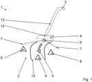
- FIG. 1 Denoted by the reference numeral 1, a vacuum cleaner 1 with a floor nozzle 4 as a suction nozzle is shown purely schematically.
- the representation according to Figure 1 shows a vacuum cleaner 1 according to the invention with a floor nozzle 4 connected to the vacuum cleaner 1.
- the vacuum cleaner 1 shown in the exemplary embodiment is a so-called cordless vacuum cleaner 1.
- the floor nozzle 4 is connected here via its connecting piece 12 to a preferably telescopically designed suction tube 13.
- a fan (not shown) of the vacuum cleaner 1, which is integrated in the vacuum cleaner housing, is powered by an accumulator in order to generate a negative pressure. By means of this negative pressure, dirt and grime are removed from the surface to be cleaned.
- a user of the vacuum cleaner 1 can grasp the handle 3 and thus push the floor nozzle 4 back and forth in pushing and pulling movements in the processing direction 5 in order to clean the floor surface 2.
- the floor nozzle 4 glides over the floor surface 2 to be cleaned. Particularly with long-pile carpets, the underside of the floor nozzle 4 glides over the floor surface 2, while with hard floors the underside hovers over these floor surfaces 2 at a distance, possibly using spacer bristles.
- the floor nozzle 4 of the vacuum cleaner 1 has an optical sensor 6, which is designed to detect a detection area 7 in the processing direction 5 in front of the floor nozzle 4.
- the floor nozzle 4 can also have an optical sensor 6 with a detection area 7 in the processing direction 5 behind the floor nozzle 4.
- a gyroscope sensor (not shown) can be provided on the vacuum cleaner 1, which detects the movement of the floor nozzle 4 over the floor surface 2 to be cleaned.
- the control device (not shown) of the vacuum cleaner 1 can use artificial intelligence to recognize and categorize various objects 8, 9 on the floor surface 2 within the detection area of the sensor 6 from the data of the optical sensor 6.
- the detected objects 8, 9 are categorized by the control device of the vacuum cleaner 1 into dangerous and non-dangerous objects. Those objects that can be sucked in via the floor nozzle 4 and would cause damage to the vacuum cleaner 1 and/or the object 9 are identified as dangerous objects 9.
- the control device can use the data from the optical sensor 6 and the gyroscope sensor to estimate a possible travel corridor 10 of the floor nozzle 4, in which the user is most likely to move the vacuum cleaner.
- a warning device (not shown) of the vacuum cleaner 1 can then be activated if a dangerous object 9 is located in the travel corridor 10 of the floor nozzle 4, in order to issue a warning signal.
- This warning signal can be perceived acoustically, visually, or haptically by the user.
- the control device can also reduce the suction air flow at the floor nozzle 4 if a dangerous object 9 is located in the travel corridor 10 of the floor nozzle 4.
- the control device can also stop the brush motor and thus the brush if a dangerous object 9 is located in the driving corridor 10 directly in front of the floor nozzle 4.
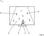
- the Figure 2 shows schematically the camera image of a camera as optical sensor 6 ( Fig. 1 ) for the vacuum cleaner according to Figure 1 .
- the floor nozzle 4 of the vacuum cleaner 1 can also be seen.
- the camera image shows the floor area 2 to be cleaned, which, due to the movement of the floor nozzle 4 in the processing direction 5, moves in the opposite direction in the camera image, along with the objects 8 located thereon.
- a moving object 11 is moving on the floor surface 2 towards the floor nozzle 4, which is indicated by the larger velocity vector.
- the control device can use the camera image to determine objects 11 moving towards the floor nozzle 4 in the detection area 7 ( Fig. 1 ) of camera 6 ( Fig. 1 ). If an object 11 is in the detection area 7 ( Fig. 1 ) of the optical sensor 6 ( Fig.
- the control device can generate a warning signal to the user of the vacuum cleaner 1 via a warning device on the vacuum cleaner 1. This prevents the unwanted suction of moving objects 11. If the floor nozzle 4 moves further towards the moving object 11, the control device can also reduce the suction air flow at the floor nozzle 4. If the floor nozzle 4 has a brush (not shown) driven by a brush motor (not shown) for cleaning the floor surface 2, the control device can also stop the brush motor if a moving object 11 moves towards the floor nozzle 4 within the detection range 7 of the optical sensor 6. This can prevent the moving object from accidentally becoming caught in the brush.
Landscapes
- Engineering & Computer Science (AREA)
- Mechanical Engineering (AREA)
- Electric Vacuum Cleaner (AREA)
Applications Claiming Priority (1)
| Application Number | Priority Date | Filing Date | Title |
|---|---|---|---|
| DE102023132952.9A DE102023132952A1 (de) | 2023-11-27 | 2023-11-27 | Staubsauger |
Publications (1)
| Publication Number | Publication Date |
|---|---|
| EP4563055A1 true EP4563055A1 (fr) | 2025-06-04 |
Family
ID=93376066
Family Applications (1)
| Application Number | Title | Priority Date | Filing Date |
|---|---|---|---|
| EP24210174.9A Pending EP4563055A1 (fr) | 2023-11-27 | 2024-10-31 | Aspirateur de poussières |
Country Status (2)
| Country | Link |
|---|---|
| EP (1) | EP4563055A1 (fr) |
| DE (1) | DE102023132952A1 (fr) |
Citations (3)
| Publication number | Priority date | Publication date | Assignee | Title |
|---|---|---|---|---|
| DE102016115392A1 (de) * | 2016-08-19 | 2018-02-22 | Miele & Cie. Kg | Bodendüse für Staubsauger und Staubsauger |
| EP3466310A1 (fr) * | 2017-10-03 | 2019-04-10 | Black & Decker Inc. | Détection de proximité |
| CN107708512B (zh) * | 2015-06-19 | 2021-04-06 | 德国福维克控股公司 | 用于吸尘器的吸嘴 |
-
2023
- 2023-11-27 DE DE102023132952.9A patent/DE102023132952A1/de active Pending
-
2024
- 2024-10-31 EP EP24210174.9A patent/EP4563055A1/fr active Pending
Patent Citations (3)
| Publication number | Priority date | Publication date | Assignee | Title |
|---|---|---|---|---|
| CN107708512B (zh) * | 2015-06-19 | 2021-04-06 | 德国福维克控股公司 | 用于吸尘器的吸嘴 |
| DE102016115392A1 (de) * | 2016-08-19 | 2018-02-22 | Miele & Cie. Kg | Bodendüse für Staubsauger und Staubsauger |
| EP3466310A1 (fr) * | 2017-10-03 | 2019-04-10 | Black & Decker Inc. | Détection de proximité |
Also Published As
| Publication number | Publication date |
|---|---|
| DE102023132952A1 (de) | 2025-05-28 |
Similar Documents
| Publication | Publication Date | Title |
|---|---|---|
| DE69821659T2 (de) | Reinigungsroboter | |
| EP1973455B1 (fr) | Suceur pour aspirateur muni d'un moyen de delimitation a soulevement ou abaissement actif et procede correspondant | |
| DE112014000174T5 (de) | Rollenbürste für Oberflächenreinigungsroboter | |
| EP3569124A1 (fr) | Appareil de nettoyage | |
| EP3310233B1 (fr) | Buse d'aspiration pour un aspirateur | |
| EP3685722A1 (fr) | Système composé d'un appareil de traitement du sol guidé exclusivement à la main et d'un appareil de traitement du sol à commande exclusivement automatique ainsi que procédé de fonctionnement d'un tel système | |
| EP3409168B1 (fr) | Module de nettoyage d'angle pour robots de nettoyage modulaires | |
| EP3683645A1 (fr) | Système doté d'un premier appareil de traitement du sol et d'un second appareil de traitement du sol ainsi que procédé de fonctionnement d'un tel système | |
| DE102023132952A1 (de) | Staubsauger | |
| DE102017112741A1 (de) | Staubsauger mit Objekterkennung und Verfahren zum Betreiben eines Staubsaugers | |
| EP4197414A1 (fr) | Robot aspirateur | |
| DE102018132964A1 (de) | Autonome reinigungsvorrichtung mit einem saugarm | |
| EP3586709B1 (fr) | Buse de sol pour aspirateur et aspirateur | |
| WO2023001390A1 (fr) | Appareil de nettoyage de sol et procédé de commande d'un appareil de nettoyage de sol | |
| EP4098166B1 (fr) | Buse pour sol pour aspirateurs, aspirateur, ensemble de brosses rotatives et procédé permettant de faire fonctionner un aspirateur | |
| DE102019104429A1 (de) | Bodenpflegegerät und Verfahren zum Betrieb eines Bodenpflegegeräts | |
| EP3446610B1 (fr) | Aspirateur et procédé de fonctionnement d'un aspirateur | |
| EP3479751B1 (fr) | Dispositif de charge pour appareil électroménager et appareil électroménager | |
| EP4212082A1 (fr) | Aspirateur, de préférence aspirateur à main | |
| DE102017119108A1 (de) | Staubsauger und Verfahren zum Betrieb eines Staubsaugers | |
| EP4702910A1 (fr) | Procédé pour détecter et éliminer un engorgement | |
| EP3944801B1 (fr) | Appareil autonome de nettoyage du sol | |
| EP3420872B1 (fr) | Buse de sol pour aspirateur et aspirateur | |
| DE102019133721B4 (de) | Vorsatzgerät für ein Reinigungsgerät und Reinigungsgerät mit Feuchteerkennung | |
| DE102019130910A1 (de) | Staubsauger und Verfahren zum Betrieb eines Staubsaugers |
Legal Events
| Date | Code | Title | Description |
|---|---|---|---|
| PUAI | Public reference made under article 153(3) epc to a published international application that has entered the european phase |
Free format text: ORIGINAL CODE: 0009012 |
|
| STAA | Information on the status of an ep patent application or granted ep patent |
Free format text: STATUS: THE APPLICATION HAS BEEN PUBLISHED |
|
| AK | Designated contracting states |
Kind code of ref document: A1 Designated state(s): AL AT BE BG CH CY CZ DE DK EE ES FI FR GB GR HR HU IE IS IT LI LT LU LV MC ME MK MT NL NO PL PT RO RS SE SI SK SM TR |
|
| STAA | Information on the status of an ep patent application or granted ep patent |
Free format text: STATUS: REQUEST FOR EXAMINATION WAS MADE |
|
| 17P | Request for examination filed |
Effective date: 20251204 |