EP3479776A1 - Dispositif de rétraction chirurgical - Google Patents
Dispositif de rétraction chirurgical Download PDFInfo
- Publication number
- EP3479776A1 EP3479776A1 EP18194970.2A EP18194970A EP3479776A1 EP 3479776 A1 EP3479776 A1 EP 3479776A1 EP 18194970 A EP18194970 A EP 18194970A EP 3479776 A1 EP3479776 A1 EP 3479776A1
- Authority
- EP
- European Patent Office
- Prior art keywords
- coarse
- drive
- fine
- base body
- retraction device
- Prior art date
- Legal status (The legal status is an assumption and is not a legal conclusion. Google has not performed a legal analysis and makes no representation as to the accuracy of the status listed.)
- Granted
Links
Images



Classifications
-
- A—HUMAN NECESSITIES
- A61—MEDICAL OR VETERINARY SCIENCE; HYGIENE
- A61B—DIAGNOSIS; SURGERY; IDENTIFICATION
- A61B17/00—Surgical instruments, devices or methods
- A61B17/02—Surgical instruments, devices or methods for holding wounds open, e.g. retractors; Tractors
- A61B17/0206—Surgical instruments, devices or methods for holding wounds open, e.g. retractors; Tractors with antagonistic arms as supports for retractor elements
Definitions
- the present invention relates to a surgical retraction device with at least two relatively movable and held directly or indirectly to each other holding arms, on each of which at least one surgical retaining element for retaining bone or bone tissue is arranged or arranged, and with a Gararmpositionier adopted for moving and changing a position of the at least two retaining arms relative to each other.
- Surgical retraction devices of the type described above are used in surgery, for example in cardiothoracic surgery. They are used in the form of so-called self-retaining blockers to get a clear access to the organs to be treated. An access to the chest of a patient takes place either between two ribs or through the previously divided sternum.
- the blockers must withstand great forces to keep access to the surgical site open.
- the retraction devices are equipped with a holding arm positioning device to allow a position of the at least two holding arms relative to one another change by moving at least one of them.
- tactility thereof is usually limited due to the construction thereof.
- Surgical retraction devices are in particular from US 2007/0161865 A1 and the US 2007/0073111 A1 known.
- the holding arm positioning device comprises a coarse adjustment device and at least one fine adjustment device with which a position of the at least two holding arms relative to each other can be changed independently.
- Such a trained Gararmpositionier allows a particularly sensitive adjustment of a distance or a specific position between the at least two holding arms. Due to the independent or separate operability of the coarse adjustment device and the at least one fine adjustment means positions of at least two support arms, it is often in such surgical retraction devices exactly two support arms prepositioned with the Grobjustage issued and dosed with the Feinjustage issued and sent to the desired end position. Due to the conventional relatively coarse holding arm positioning means, a feedback or feeling between the tissues or bones to be spread and the user is almost lost, so that partial sternal and / or rib fractures occur when an operator with the not very sensitively operable holding arm positioning means moves a distance the at least two holding arms are slightly too large relative to each other.
- the structure of the surgical retraction device is particularly simple if the coarse adjustment device and / or the at least one fine adjustment device are formed for moving the at least two support arms parallel to each other and / or away from each other.
- the at least two retaining arms can be moved relative to each other in such adjustment devices.
- the coarse adjustment device and / or the at least one fine adjustment device are designed to pivot the at least two support arms about at least one pivot axis toward one another and / or away from one another.
- the coarse adjustment device can be designed in the form of a displacement device for the at least two retaining arms, which has at least one fine adjustment device in the form of a displacement or pivoting device.
- the retraction device comprises two retaining arms
- a construction of the surgical retraction device can be simplified, in particular, by comprising a base body on which at least one of the at least two holding arms is movably held.
- two retaining arms are held movably on the base body.
- more holding arms can be held movably on the base body.
- the holding arms which are movably held on the main body can then be moved and positioned individually with the holding arm positioning device relative to one another and also to the main body.
- the surgical retraction device can be handled particularly easily if a holding arm is fixedly arranged on the base body. A change in distance or position of the at least two retaining arms relative to one another takes place in this case by changing a position of a further retaining arm relative to the base body.
- the coarse adjustment device comprises a coarse drive device for moving one of the at least two retaining arms and the base body relative to one another.
- the coarse adjustment device With the coarse adjustment device, one of the holding arms can be roughly positioned relative to the main body or to another holding arm.
- the coarse toothed rack drive comprises a coarse tooth row on the base body and a coarse bearing element displaceably mounted on the base body, if a coarse drive element is movably mounted on the coarse bearing element, which meshes with the coarse tooth row, and if, as a result of a movement of the coarse drive element relative to the coarse bearing element, the coarse bearing element is movable relative to the base body.
- the structure of the surgical retraction device can be further simplified if the coarse drive member is designed in the form of a coarse toothed wheel. It is particularly adapted to a toothing of the coarse tooth series.
- the coarse drive member is rotatably mounted about a Grobantriebsgliedrotationsachse on the coarse bearing element, which extends transversely to a longitudinal axis of the base body.
- a longitudinal axis of the basic body can in particular also be a longitudinal axis of a basic body section if the basic body is not rectilinear.
- the large bearing element are moved parallel to the longitudinal axis of the body.
- the coarse adjustment device In order to operate the coarse adjustment device in a simple manner, it is advantageous if it comprises a coarse operating element for moving the coarse drive member relative to the coarse bearing element.
- the at least one fine adjustment device is designed in the form of a first fine drive means for moving one of the at least two retaining arms and the base body relative to each other.
- the first fine drive device allows a sensitive and metered positioning of the at least two holding arms relative to each other.
- the fine rack drive comprises a fine tooth row on the base body and a bearing body slidably mounted on the fine bearing element, when the fine bearing element a toothed Feinantriebsglied is movably mounted, which is in engagement with the Feinschwhol, and if due to a movement of the fine drive member relative to the fine bearing element, the fine bearing element is movable relative to the base body.
- the fine tooth row favorably has a pitch that corresponds to a multiple of a tooth pitch of the coarse tooth row, for example, two to five times. This in turn makes it possible to set the distance between two or five times finer a distance or a relative position between the at least two holding arms.
- the fine drive member is designed in the form of a fine gear.
- the fine drive member is mounted rotatably about a Feinantriebsgliedrotationsachse on the fine bearing element, which extends transversely to a longitudinal axis of the base body.
- This arrangement makes it possible, by simply rotating the fine drive member about the Feinantriebsgliedrotationsachse the fine bearing element on which a support arm can be arranged fixed or movable, to move parallel to the longitudinal axis of the body.
- the surgical retraction device comprises a fine-actuating element for moving the fine-drive element relative to the fine-bearing element.
- the coarse tooth row and / or the fine tooth row each extend to a free end of the base body.
- the coarse tooth row and the fine tooth row can be formed in the same side surface of the main body, but also in different side surfaces.
- the coarse tooth row and the fine tooth row are formed on the base body in such a way that they point away from each other in different directions. They can also be arranged or formed on the same portion of the body.
- the at least one fine adjustment device is designed in the form of a second fine drive device for pivoting a holding arm relative to the main body.
- the holding arm may be arranged on a fine bearing element, which may be designed to be stationary or movable relative to the main body.
- the second fine drive device makes it possible in a simple manner to pivot the at least one holding arm relative to the base body in a defined manner and sensitively.
- the surgical retraction device when the second fine drive means is arranged or formed on the coarse bearing element or on the base body.
- the second fine drive device it is also conceivable to arrange the second fine drive device on a separate bearing element, which is held movably on the base body.
- a bearing element of the second fine drive device could also be arranged or formed fixedly on the base body.
- the at least one holding arm can be pivoted when the second fine drive device comprises a fine-spindle drive.
- a rotational movement of the fine spindle drive or a part thereof can thus be converted in a simple manner into a pivoting movement of the at least one holding arm relative to the main body.
- the structure of the fine spindle drive is particularly simple if it comprises a drive spindle which is in contact with a holding arm or the coarse bearing element, and if, as a result of movement of the drive spindle, the holding arm can be pivoted relative to the main body about a pivot axis.
- the drive spindle is screwed in a drive spindle guide.
- the drive spindle can be rotated about its longitudinal axis and thereby perform a screw movement relative to the drive spindle guide.
- the drive spindle guide is arranged or formed on the coarse bearing element or on the base body.
- This construction makes it possible to coarsely adjust a support arm mounted on the coarse bearing element by means of the coarse adjustment device and to finely adjust it by means of the second fine drive device arranged on the coarse bearing element or on the main body.
- the drive spindle comprises a fine thread.
- the surgical retraction device further comprises a stop device for limiting movement of the at least two holding arms relative to one another. This ensures that the holding arms are not moved completely uncontrolled. Especially in the case of cardiac or thorax surgery, this could have negative consequences for a patient.
- the surgical retraction device comprises a locking device for fixing the at least two retaining arms movable relative to one another in an adjustment position in a retaining position relative to one another.
- the at least two retaining arms which can be changed in their position in the adjustment position can be fixed relative to one another after reaching the relative position desired by the operator, so that the retraction device then assumes the retaining position.
- the retaining arms are designed to be straight or curved.
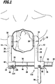
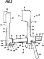
- FIGS. 1 to 4 A first embodiment of a surgical retraction device, which is also referred to below as a blocker, is in the FIGS. 1 to 4 generally designated by the reference numeral 10. It comprises two holding arms 12 and 14, which are movable relative to one another and held indirectly to one another, on each of which a surgical retaining element 16 or 18 is integrally formed.
- a surgical retaining element 16 or 18 is integrally formed.
- retaining elements 16 and 18 each have a substantially groove-shaped receptacle 20 or 22, into which a rib or a half of a severed sternum, as in FIG. 1 shown, engage and so can be retained by the retaining elements 16 and 18.
- the support arms 12 and 14 each define longitudinal axes 24 and 26 which are parallel to each other. They are essentially defined by a flat block-shaped holding section 28 and 30, respectively, carrying the retaining element 16 and 18 at one end and a bearing element at the other end thereof, namely the bearing arm 12 a coarse bearing element 32 and the retaining section 30 a fine bearing element 34 Groblagerelement 32 and the fine bearing element 34 are both movably held movably on a base body 36 of the surgical retraction device 10, wherein the base body 36 is formed in the form of a cuboid bar or rail.
- the main body 36 is provided with two serrations defining a coarse tooth row 38 and a fine tooth row 40.
- the coarse tooth row 38 is formed starting from a first end 42 over about three quarters of a total length of the base body 36 on a narrow side edge 44 and includes vertically projecting, rounded teeth 46.
- the Feinffysch 40 extends with a plurality of teeth 50, which are formed in the same side edge 44.
- a narrow side edge 52 of the base body 36 extending parallel to the side edge 44 also extends parallel to a longitudinal axis 54 defined by the base body 36.
- the large bearing element 32 is in the form of a cuboid and provided with a groove-shaped receptacle 76 which has a width which corresponds to a width of the base body 36.
- a bottom 58 of the receptacle 56 abuts against the side edge 52.
- the receptacle 56 laterally delimiting side walls 60 and 62 abut the side edges 44 and 52 interconnecting side surfaces 62 and protrude with their free end surfaces 64 on the side edge 44.
- the receptacle 56 is closed by a block-shaped closure body 66 which has a length corresponding to the coarse bearing element 32 parallel to the longitudinal axis 54.
- An upper side 68 of the closure body 66 is located on the teeth 46, an underside 70 of the closure body 66 terminates flush with the end faces 64.
- the large bearing element 32 is guided so defined guided parallel to the longitudinal axis 54 on the base body 36 slidably.
- a coarse drive device 72 For defined movement of the coarse bearing element 32 on the base body 36 is a coarse drive device 72, which is designed to move the support arm 12 and the base body 36 relative to each other and in the form of a coarse toothed rack drive 74.
- the coarse drive device 72 forms part of a coarse adjustment device 76, with which a position of the support arms 12 and 14 relative to each other is changeable.
- the coarse toothed drive 74 comprises the coarse tooth row 38, the coarse bearing element 32 and a toothed coarse drive element 78, which engages with the coarse tooth row 38. It is rotatably mounted about a Grobantriebsgliedrotationsachse 80 on Grobagerelement 32, which extends transversely to the longitudinal axis 54 of the base body 36.
- the large bearing element 32 is provided with a transverse bore 82, which passes through the two side walls 60 and is arranged such that in the closure body 66 in the direction of the coarse tooth row 38 facing recess 84 is formed, which has the shape of a half hollow cylinder.
- a rotary body 86 has a first end with a flat cylindrical portion 88 which is positively inserted into the transverse bore 82 in a side wall 60 and does not project into the receptacle 56.
- the section 88 is followed by a cylindrical stop body 90, which has an outer diameter which is slightly larger than the transverse bore 82.
- An end portion 92, which adjoins the stop body 90, has a diameter which is slightly smaller than that It is also provided transversely to the Grobantriebsgliedrotationsachse 80 with a bore 94 which serves to receive a bearing pin 96, which projects beyond the end portion 92 on both sides.
- a coarse operating element 98 designed in the form of an actuating lever, which has a U-shaped end 100 with two parallel bearing legs 102, between which the end section 92 engages, each of which is provided with a bore 104 in which the bearing pin 96 is used rotatably.
- An outer diameter of the bearing pin 96 is slightly smaller than an inner diameter of the bore 94, so that the bearing pin 96 and the coarse actuating element 98 fixed thereto can be pivoted about a longitudinal axis 106 defined by the bore 94.
- the coarse drive element 78 which comprises the section 88 and the toothed pins 108, meshes with the coarse tooth row 38 in the form of a coarse gear wheel 112 so that the coarse bearing element 32 and thus the support arm 12 moves either in the direction of the end 42 During a rotation of the coarse actuating element 98 about the Grobretesgliedrotationsachse 80 in the counterclockwise direction or in a clockwise direction in the direction of the end 48 back.
- the retraction device 10 further comprises a fine adjustment device 114, which forms a holding arm positioning device 116 together with the coarse adjustment device 76.
- the fine adjustment device 114 is configured to change a position of the support arm 14 relative to the base body 36. With the coarse adjustment device 76 and with the fine adjustment device 114, the two support arms 12 and 14 can be moved relative to each other and independently and thus a relative position thereof can be changed.
- the fine adjustment device 114 is configured in the form of a first fine drive device 118 for moving the holding arm 14 and the base body 16 relative to one another. It is designed in the form of a fine toothed rack drive 120, which comprises the fine tooth row 40 and the fine storage element 34.
- the fine bearing element 34 is in the form of a cuboid formed with a groove-shaped receptacle 122 which has a bottom 124 which rests against the side edge 52.
- the receptacle 122 is bounded laterally by two parallel side walls 126, which bear against the side surfaces 62 of the base body 36.
- a block-shaped closure body 130 rests with its upper side 132 on the side edge 44 and closes with its underside 134 flush with the end faces 128. It is inserted into the receptacle 122 so that the fine bearing element 34 can be displaced parallel to the longitudinal axis 54 on the base body 36.
- the Feinierestangenantrieb 120 further includes a fine drive member 136 which is mounted rotatably about a Feinantriebsgliedrotationsachse 138 on the fine bearing element 34. It is defined by a transverse bore 140, which passes through the two side walls 126. The transverse bore 140 further forms a recess 142 in the closure body 130, which is open towards the side edge 44 and has the shape of a half-hollow cylinder.
- the fine drive member 136 comprises a rotary body 144, with a flat cylindrical portion 146 which engages positively in the transverse bore 140 in a side wall 126. The portion 146 does not protrude into the receptacle 122.
- a substantially cuboidal fine actuating element 150 is formed on the abutment body 148 and forms a kind of actuating knob for the fine drive member 136.
- This further comprises two toothed pins 152 which are arranged from the portion 146 parallel to each other and the Feinantriebsgliedrotationsachse 138 perpendicularly from the portion 146 projecting.
- the toothed pins 152 are arranged at a distance from one another which corresponds to a spacing of the teeth 50. They are relative to the Feinantriebsgliedrotationsachse 138 arranged diametrically opposite one another.
- the toothed pins 152 which together with the portion 156 form a fine gear 154, are engageable with the teeth 50 and can comb with these.
- a further bearing plate 153 is positively inserted, on which the toothed pins 152 are additionally secured.
- a clockwise rotation of the fine operating member 150 moves the fine bearing member 34 toward the end 48, and rotation of the fine operating member 150 in a counterclockwise direction results in a sliding movement of the fine bearing member 34 toward the end 42.
- FIG. 1 An operator can, as in FIG. 1 shown, after severing the sternum insert the retraction device 10 in the cut so that the receptacles 20 and 22 of the retaining elements 16 and 18 each receive a portion of the severed sternum.
- the actuator 98 By rotation of the actuator 98 in the counterclockwise direction, the retaining elements 16 and 18 are moved away from each other. A rough adjustment is thus possible with the coarse adjustment device 76.
- the distance of the teeth 50 is about half as large as a distance of the teeth 46.
- full rotation of the fine actuator 150 around the Feinantriebsgliedrotationsachse 138 only half feed the fine bearing element 34 compared with a feed of the Grobagerelements 32 at a full revolution of the coarse actuator 98 the Grobantriebsgliedrotationsachse 80.
- An operator can thus by means of Feinjustage adopted 114 a distance between the support arms 12 and 14 and thus between the retaining elements 16 and 18 clearly sensitive dosing than only with the coarse adjustment device 76 alone.
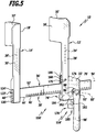
- FIGS Figures 5 and 6 Another embodiment of a surgical retraction apparatus, generally designated by the reference numeral 10 ', is incorporated in FIGS Figures 5 and 6 shown schematically. Parts of the retraction device 10 'that are identical or functionally designed with parts of the retraction device 10 are referred to below and in the figures with identical reference numerals with an additional coat.
- the base body 36 ' is analogous to the base body 36, but it has only one coarse tooth row 38' with teeth 46 'on.
- the holding arm 14 ' At the end 48 'of the base body 36' is the holding arm 14 'with its longitudinal axis 26' perpendicular to the longitudinal axis 54 'fixedly arranged.
- a receptacle 122 ' is formed analogous to the receptacle 122 at one end of the support arm 14'.
- a closure body 130 ' closes the receptacle 122' and bears against the side edge 44 'of the main body 36', a bottom 124 'of the receptacle 122' the side edge 52 'of the base body 36'.
- the cuboid Grobagerelement 32 ' On the base body 36 'displaceable parallel to the longitudinal axis 54', the cuboid Grobagerelement 32 'is held. It can be moved by means of the coarse adjustment device 76 'analogous to the coarse adjustment device 76.
- a Feinjustage issued 114 ' is, unlike the retraction device 10, not directly on the base body 36' stored, but on the Grobagerelement 32 '. This has for this purpose a parallel to the longitudinal axis 54 'of the coarse bearing element 32' protruding projection which rests with its bottom 158 on the side edge 52 '.
- a substantially L-shaped end 160 of the support arm 12 ' comprises a leg 162 projecting approximately 90 ° relative to the longitudinal axis 24'.
- a portion of the L-shaped end 160 extending parallel to the longitudinal axis 24 ' is provided with a guide slot 166 which has a width which corresponds to a width of the base body 36 ', so that the base body 36' can pass through the guide slot 166.
- the section 164 is traversed in the region of the guide slot 166 with a bore 168, which also extends through the bearing projection 156.
- the portion 164 is coupled to the bearing projection 156 by means of a bearing pin 170 which is non-rotatably connected to the portion 164 and has an outer diameter which is slightly smaller than the bore 168 passing through the bearing projection 156.
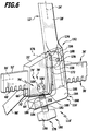
- a stop surface 174 is formed, which is inclined by approximately 5 ° to 15 ° relative to a plane defined by the side surface 172, which is oriented perpendicular to the longitudinal axis 54 '. If the holding arm 12 'is pivoted about a pivot axis 176 defined by the bearing pin 170, this is possible only until the portion 164 abuts the stop surface 174.
- the fine adjustment device 114 'in the form of a second fine drive device 178 is formed. It is arranged on the coarse bearing element 32 'and comprises a fine spindle drive 180.
- the fine spindle drive 180 comprises a drive spindle 182, which is formed in a drive spindle guide 184 in the form of a bore provided with an internal thread on the leg 162.
- the drive spindle 182 is provided with an external thread in the form of a fine thread 186 which is formed corresponding to the internal thread of the bore 162 formed on the leg.
- a free end 188 of the drive spindle 182 abuts on the underside 70 'of the closure body 66'.
- a knob 190 is formed, which forms a fine actuating element.
- the retraction device 10 'thus also comprises a stop device 192' for limiting movement of the holding arm 12 'relative to the holding arm 14' or to the main body 36 '.
- the drive spindle guide 184 is thus formed on the support arm 12 '. Alternatively, it may also be arranged or formed on the large bearing element 32 '. With the fine adjustment device 114 ', the support arms 12' and 14 'can be pivoted relative to each other to continuously increase a distance between the retention members 16' and 18 '.
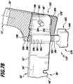
- FIG. 7 A further embodiment of a retraction device designated overall by the reference numeral 10 "is shown in FIG. 7 shown schematically. you differs from the retraction device 10 'essentially only in that the holding arm 14 "relative to the base body 36" can be pivoted by means of another Feinjustage issued 114 ".
- the fine-spindle drive 180 ' comprises a drive spindle guide 184', which is shaped in the form of a sleeve 194 "formed on the main body 36, which has an internal thread 196.
- the end 48 engages a groove 198 of the free end 200 of the support arm 14".
- the holding arm 14 is provided in the region of the groove 198, just like the latter, with a bore 202, into which a bearing pin 204 is inserted, the longitudinal axis of which is oriented perpendicular to the longitudinal axis 54" of the base body 36.
- Above the lateral edge 52 “stands of the holding arm 14 "from a projection 206, which points in the direction of the end 42" out.
- the end 188 'of the drive spindle 182' is in contact with the projection 206.
- a stopper 192 ' is formed by a bottom 208 of the groove 198 in conjunction with an upper stop surface 210 of the closure body 130 ".
Landscapes
- Health & Medical Sciences (AREA)
- Life Sciences & Earth Sciences (AREA)
- Surgery (AREA)
- Heart & Thoracic Surgery (AREA)
- Engineering & Computer Science (AREA)
- Biomedical Technology (AREA)
- Nuclear Medicine, Radiotherapy & Molecular Imaging (AREA)
- Medical Informatics (AREA)
- Molecular Biology (AREA)
- Animal Behavior & Ethology (AREA)
- General Health & Medical Sciences (AREA)
- Public Health (AREA)
- Veterinary Medicine (AREA)
- Surgical Instruments (AREA)
Applications Claiming Priority (2)
| Application Number | Priority Date | Filing Date | Title |
|---|---|---|---|
| DE102009018139A DE102009018139A1 (de) | 2009-04-16 | 2009-04-16 | Chirurgische Retraktionsvorrichtung |
| EP10158282.3A EP2241262B1 (fr) | 2009-04-16 | 2010-03-30 | Dispositif de rétraction chirurgical |
Related Parent Applications (1)
| Application Number | Title | Priority Date | Filing Date |
|---|---|---|---|
| EP10158282.3A Division EP2241262B1 (fr) | 2009-04-16 | 2010-03-30 | Dispositif de rétraction chirurgical |
Publications (2)
| Publication Number | Publication Date |
|---|---|
| EP3479776A1 true EP3479776A1 (fr) | 2019-05-08 |
| EP3479776B1 EP3479776B1 (fr) | 2021-06-09 |
Family
ID=42340755
Family Applications (2)
| Application Number | Title | Priority Date | Filing Date |
|---|---|---|---|
| EP18194970.2A Active EP3479776B1 (fr) | 2009-04-16 | 2010-03-30 | Dispositif de rétraction chirurgicale |
| EP10158282.3A Active EP2241262B1 (fr) | 2009-04-16 | 2010-03-30 | Dispositif de rétraction chirurgical |
Family Applications After (1)
| Application Number | Title | Priority Date | Filing Date |
|---|---|---|---|
| EP10158282.3A Active EP2241262B1 (fr) | 2009-04-16 | 2010-03-30 | Dispositif de rétraction chirurgical |
Country Status (4)
| Country | Link |
|---|---|
| US (1) | US20100268036A1 (fr) |
| EP (2) | EP3479776B1 (fr) |
| DE (1) | DE102009018139A1 (fr) |
| ES (1) | ES2880400T3 (fr) |
Families Citing this family (11)
| Publication number | Priority date | Publication date | Assignee | Title |
|---|---|---|---|---|
| CN102727264B (zh) * | 2012-06-07 | 2014-07-30 | 上海交通大学医学院附属上海儿童医学中心 | 一种延迟关胸胸骨支撑架 |
| US9289199B1 (en) * | 2014-01-09 | 2016-03-22 | Neotech Products, Inc. | Retinal examination apparatus |
| CN103750871A (zh) * | 2014-01-22 | 2014-04-30 | 张宗贤 | 一种人体外科手术用切口撑开器 |
| US9999414B2 (en) * | 2014-01-24 | 2018-06-19 | Contour Surgical, Inc. | Retraction devices and methods of its use and manufacture |
| GB2543468B (en) | 2014-08-13 | 2021-11-03 | Nuvasive Inc | Minimally disruptive retractor and associated methods for spinal surgery |
| US10624622B2 (en) * | 2016-04-19 | 2020-04-21 | Worcester Polytechnic Institute | Surgical retraction device |
| US11602337B2 (en) * | 2019-04-24 | 2023-03-14 | Nuvasive, Inc. | Transmission assembly |
| EP4647033A3 (fr) * | 2019-08-21 | 2026-01-21 | LSI Solutions, Inc. | Appareil ascendeur sternal |
| CN110495919B (zh) * | 2019-09-30 | 2021-02-02 | 河南省洛阳正骨医院(河南省骨科医院) | 一种全方位肌肉牵开器 |
| CN114848054A (zh) * | 2022-05-10 | 2022-08-05 | 华中科技大学同济医学院附属协和医院 | 一种外科手术扩大视野用双控位牵开器 |
| US20240341741A1 (en) * | 2023-03-31 | 2024-10-17 | Astura Medical Inc. | Tissue retractor having a bevel gear driven retractor blade |
Citations (3)
| Publication number | Priority date | Publication date | Assignee | Title |
|---|---|---|---|---|
| US20040225196A1 (en) * | 2003-05-09 | 2004-11-11 | Ruane Bernard Joseph | Expandable and pivotally adjustable surgical retractor |
| US20050277812A1 (en) * | 2004-06-14 | 2005-12-15 | Myles Robert T | Minimally invasive surgical spinal exposure system |
| US20060271096A1 (en) * | 2002-10-25 | 2006-11-30 | Hamada James S | Minimal incision maximal access MIS spine instrumentation and method |
Family Cites Families (14)
| Publication number | Priority date | Publication date | Assignee | Title |
|---|---|---|---|---|
| US651470A (en) * | 1900-02-23 | 1900-06-12 | George P Pilling | Speculum. |
| US1727879A (en) * | 1929-03-25 | 1929-09-10 | Sharp & Smith Inc | Retractor |
| US1968094A (en) * | 1931-06-23 | 1934-07-31 | Spencer Lens Co | Microscope |
| US5088472A (en) * | 1990-04-04 | 1992-02-18 | Mehdi Fakhrai | Retractor |
| CA2075241A1 (fr) * | 1991-10-03 | 1993-04-04 | Stephen W. Gerry | Manche pour manipuler un outil de laparascopie |
| US5688223A (en) * | 1995-11-08 | 1997-11-18 | Minnesota Scientific, Inc. | Retractor support with adjustable retractor blades |
| US5944658A (en) * | 1997-09-23 | 1999-08-31 | Koros; Tibor B. | Lumbar spinal fusion retractor and distractor system |
| US6224545B1 (en) * | 1998-07-24 | 2001-05-01 | Core Surgical, Inc. | Surgical retractor and method for use |
| US7637914B2 (en) * | 2004-08-04 | 2009-12-29 | Leslie Stern | Surgical base unit and retractor support mechanism |
| US7537565B2 (en) * | 2005-09-27 | 2009-05-26 | Daniel Bass | Surgical retractor with rotating blades |
| US8267859B2 (en) * | 2005-09-28 | 2012-09-18 | Holmed Corporation | Spreader insert for a retractor system |
| US7824332B2 (en) * | 2006-01-11 | 2010-11-02 | Mehdi Fakhrai | Retractor |
| US7935053B2 (en) * | 2006-06-06 | 2011-05-03 | Globus Medical, Inc | Surgical Retractor System |
| US7931589B2 (en) * | 2006-11-09 | 2011-04-26 | Ebi, Llc | Surgical retractor device and related methods |
-
2009
- 2009-04-16 DE DE102009018139A patent/DE102009018139A1/de not_active Withdrawn
-
2010
- 2010-03-30 EP EP18194970.2A patent/EP3479776B1/fr active Active
- 2010-03-30 ES ES18194970T patent/ES2880400T3/es active Active
- 2010-03-30 EP EP10158282.3A patent/EP2241262B1/fr active Active
- 2010-04-06 US US12/798,608 patent/US20100268036A1/en not_active Abandoned
Patent Citations (3)
| Publication number | Priority date | Publication date | Assignee | Title |
|---|---|---|---|---|
| US20060271096A1 (en) * | 2002-10-25 | 2006-11-30 | Hamada James S | Minimal incision maximal access MIS spine instrumentation and method |
| US20040225196A1 (en) * | 2003-05-09 | 2004-11-11 | Ruane Bernard Joseph | Expandable and pivotally adjustable surgical retractor |
| US20050277812A1 (en) * | 2004-06-14 | 2005-12-15 | Myles Robert T | Minimally invasive surgical spinal exposure system |
Also Published As
| Publication number | Publication date |
|---|---|
| EP3479776B1 (fr) | 2021-06-09 |
| ES2880400T3 (es) | 2021-11-24 |
| EP2241262A1 (fr) | 2010-10-20 |
| EP2241262B1 (fr) | 2018-09-19 |
| DE102009018139A1 (de) | 2010-10-21 |
| US20100268036A1 (en) | 2010-10-21 |
Similar Documents
| Publication | Publication Date | Title |
|---|---|---|
| EP2241262B1 (fr) | Dispositif de rétraction chirurgical | |
| EP2510888B1 (fr) | Dispositif de manipulation pour un instrument de chirurgie micro-invasive | |
| EP2112909B1 (fr) | Instrument chirurgical | |
| DE102010006846B4 (de) | Chirurgisches Instrument | |
| DE60317702T2 (de) | Orthopädische zange mit ratsche | |
| EP1014879A1 (fr) | Tournevis medical | |
| WO2007031132A1 (fr) | Tournevis pour vis a os | |
| EP2594210A1 (fr) | Instrument médical | |
| DE102015105931A1 (de) | Medizinische Führungsvorrichtung | |
| EP2787903B1 (fr) | Instrument médical | |
| EP3035877B1 (fr) | Instrument chirurgical permettant de manipuler, positionner et fixer une tige chirurgicale par rapport à un implant chirurgical | |
| DE202011052256U1 (de) | Medizinisches Instrument | |
| EP3592253B1 (fr) | Système de gabarit de scie à usage médical | |
| DE102014101009A1 (de) | Knochenspreizer mit verdrehbaren Valven | |
| EP1629785B1 (fr) | Pince médicale | |
| EP3815642B1 (fr) | Cartouche de lame et instrument pour sceller | |
| EP3250133B1 (fr) | Instrument d'arbre pour buts chirurgicals | |
| DE102013107308A1 (de) | Stabeinsetzinstrument | |
| DE202009005768U1 (de) | Chirurgische Retraktionsvorrichtung | |
| EP1491155A1 (fr) | Instrument medical à tige coulissante, en particulier poinçonneuse à tissu | |
| DE102006016214A1 (de) | Chirurgischer Instrumentengriff und chirurgisches Instrument | |
| DE202015008921U1 (de) | Chirurgisches Instrument | |
| EP3735919B1 (fr) | Instrument médical | |
| DE202009009562U1 (de) | Chirurgisches Schiebeschaft-Instrument | |
| DE19819382C1 (de) | Chirurgisches Instrument |
Legal Events
| Date | Code | Title | Description |
|---|---|---|---|
| PUAI | Public reference made under article 153(3) epc to a published international application that has entered the european phase |
Free format text: ORIGINAL CODE: 0009012 |
|
| STAA | Information on the status of an ep patent application or granted ep patent |
Free format text: STATUS: THE APPLICATION HAS BEEN PUBLISHED |
|
| AC | Divisional application: reference to earlier application |
Ref document number: 2241262 Country of ref document: EP Kind code of ref document: P |
|
| AK | Designated contracting states |
Kind code of ref document: A1 Designated state(s): AT BE BG CH CY CZ DE DK EE ES FI FR GB GR HR HU IE IS IT LI LT LU LV MC MK MT NL NO PL PT RO SE SI SK SM TR |
|
| STAA | Information on the status of an ep patent application or granted ep patent |
Free format text: STATUS: REQUEST FOR EXAMINATION WAS MADE |
|
| 17P | Request for examination filed |
Effective date: 20191108 |
|
| RBV | Designated contracting states (corrected) |
Designated state(s): AT BE BG CH CY CZ DE DK EE ES FI FR GB GR HR HU IE IS IT LI LT LU LV MC MK MT NL NO PL PT RO SE SI SK SM TR |
|
| STAA | Information on the status of an ep patent application or granted ep patent |
Free format text: STATUS: EXAMINATION IS IN PROGRESS |
|
| 17Q | First examination report despatched |
Effective date: 20200102 |
|
| GRAP | Despatch of communication of intention to grant a patent |
Free format text: ORIGINAL CODE: EPIDOSNIGR1 |
|
| STAA | Information on the status of an ep patent application or granted ep patent |
Free format text: STATUS: GRANT OF PATENT IS INTENDED |
|
| INTG | Intention to grant announced |
Effective date: 20210112 |
|
| GRAS | Grant fee paid |
Free format text: ORIGINAL CODE: EPIDOSNIGR3 |
|
| GRAA | (expected) grant |
Free format text: ORIGINAL CODE: 0009210 |
|
| STAA | Information on the status of an ep patent application or granted ep patent |
Free format text: STATUS: THE PATENT HAS BEEN GRANTED |
|
| AC | Divisional application: reference to earlier application |
Ref document number: 2241262 Country of ref document: EP Kind code of ref document: P |
|
| AK | Designated contracting states |
Kind code of ref document: B1 Designated state(s): AT BE BG CH CY CZ DE DK EE ES FI FR GB GR HR HU IE IS IT LI LT LU LV MC MK MT NL NO PL PT RO SE SI SK SM TR |
|
| REG | Reference to a national code |
Ref country code: GB Ref legal event code: FG4D Free format text: NOT ENGLISH |
|
| REG | Reference to a national code |
Ref country code: CH Ref legal event code: EP Ref country code: AT Ref legal event code: REF Ref document number: 1399826 Country of ref document: AT Kind code of ref document: T Effective date: 20210615 |
|
| REG | Reference to a national code |
Ref country code: DE Ref legal event code: R096 Ref document number: 502010016925 Country of ref document: DE |
|
| REG | Reference to a national code |
Ref country code: IE Ref legal event code: FG4D Free format text: LANGUAGE OF EP DOCUMENT: GERMAN |
|
| REG | Reference to a national code |
Ref country code: LT Ref legal event code: MG9D |
|
| PG25 | Lapsed in a contracting state [announced via postgrant information from national office to epo] |
Ref country code: FI Free format text: LAPSE BECAUSE OF FAILURE TO SUBMIT A TRANSLATION OF THE DESCRIPTION OR TO PAY THE FEE WITHIN THE PRESCRIBED TIME-LIMIT Effective date: 20210609 Ref country code: HR Free format text: LAPSE BECAUSE OF FAILURE TO SUBMIT A TRANSLATION OF THE DESCRIPTION OR TO PAY THE FEE WITHIN THE PRESCRIBED TIME-LIMIT Effective date: 20210609 Ref country code: LT Free format text: LAPSE BECAUSE OF FAILURE TO SUBMIT A TRANSLATION OF THE DESCRIPTION OR TO PAY THE FEE WITHIN THE PRESCRIBED TIME-LIMIT Effective date: 20210609 Ref country code: BG Free format text: LAPSE BECAUSE OF FAILURE TO SUBMIT A TRANSLATION OF THE DESCRIPTION OR TO PAY THE FEE WITHIN THE PRESCRIBED TIME-LIMIT Effective date: 20210909 |
|
| REG | Reference to a national code |
Ref country code: NL Ref legal event code: MP Effective date: 20210609 |
|
| REG | Reference to a national code |
Ref country code: ES Ref legal event code: FG2A Ref document number: 2880400 Country of ref document: ES Kind code of ref document: T3 Effective date: 20211124 |
|
| PG25 | Lapsed in a contracting state [announced via postgrant information from national office to epo] |
Ref country code: LV Free format text: LAPSE BECAUSE OF FAILURE TO SUBMIT A TRANSLATION OF THE DESCRIPTION OR TO PAY THE FEE WITHIN THE PRESCRIBED TIME-LIMIT Effective date: 20210609 Ref country code: NO Free format text: LAPSE BECAUSE OF FAILURE TO SUBMIT A TRANSLATION OF THE DESCRIPTION OR TO PAY THE FEE WITHIN THE PRESCRIBED TIME-LIMIT Effective date: 20210909 Ref country code: SE Free format text: LAPSE BECAUSE OF FAILURE TO SUBMIT A TRANSLATION OF THE DESCRIPTION OR TO PAY THE FEE WITHIN THE PRESCRIBED TIME-LIMIT Effective date: 20210609 Ref country code: GR Free format text: LAPSE BECAUSE OF FAILURE TO SUBMIT A TRANSLATION OF THE DESCRIPTION OR TO PAY THE FEE WITHIN THE PRESCRIBED TIME-LIMIT Effective date: 20210910 |
|
| PG25 | Lapsed in a contracting state [announced via postgrant information from national office to epo] |
Ref country code: CZ Free format text: LAPSE BECAUSE OF FAILURE TO SUBMIT A TRANSLATION OF THE DESCRIPTION OR TO PAY THE FEE WITHIN THE PRESCRIBED TIME-LIMIT Effective date: 20210609 Ref country code: RO Free format text: LAPSE BECAUSE OF FAILURE TO SUBMIT A TRANSLATION OF THE DESCRIPTION OR TO PAY THE FEE WITHIN THE PRESCRIBED TIME-LIMIT Effective date: 20210609 Ref country code: PT Free format text: LAPSE BECAUSE OF FAILURE TO SUBMIT A TRANSLATION OF THE DESCRIPTION OR TO PAY THE FEE WITHIN THE PRESCRIBED TIME-LIMIT Effective date: 20211011 Ref country code: NL Free format text: LAPSE BECAUSE OF FAILURE TO SUBMIT A TRANSLATION OF THE DESCRIPTION OR TO PAY THE FEE WITHIN THE PRESCRIBED TIME-LIMIT Effective date: 20210609 Ref country code: SK Free format text: LAPSE BECAUSE OF FAILURE TO SUBMIT A TRANSLATION OF THE DESCRIPTION OR TO PAY THE FEE WITHIN THE PRESCRIBED TIME-LIMIT Effective date: 20210609 Ref country code: SM Free format text: LAPSE BECAUSE OF FAILURE TO SUBMIT A TRANSLATION OF THE DESCRIPTION OR TO PAY THE FEE WITHIN THE PRESCRIBED TIME-LIMIT Effective date: 20210609 Ref country code: EE Free format text: LAPSE BECAUSE OF FAILURE TO SUBMIT A TRANSLATION OF THE DESCRIPTION OR TO PAY THE FEE WITHIN THE PRESCRIBED TIME-LIMIT Effective date: 20210609 |
|
| PG25 | Lapsed in a contracting state [announced via postgrant information from national office to epo] |
Ref country code: PL Free format text: LAPSE BECAUSE OF FAILURE TO SUBMIT A TRANSLATION OF THE DESCRIPTION OR TO PAY THE FEE WITHIN THE PRESCRIBED TIME-LIMIT Effective date: 20210609 |
|
| REG | Reference to a national code |
Ref country code: DE Ref legal event code: R097 Ref document number: 502010016925 Country of ref document: DE |
|
| PLBE | No opposition filed within time limit |
Free format text: ORIGINAL CODE: 0009261 |
|
| STAA | Information on the status of an ep patent application or granted ep patent |
Free format text: STATUS: NO OPPOSITION FILED WITHIN TIME LIMIT |
|
| PG25 | Lapsed in a contracting state [announced via postgrant information from national office to epo] |
Ref country code: DK Free format text: LAPSE BECAUSE OF FAILURE TO SUBMIT A TRANSLATION OF THE DESCRIPTION OR TO PAY THE FEE WITHIN THE PRESCRIBED TIME-LIMIT Effective date: 20210609 |
|
| 26N | No opposition filed |
Effective date: 20220310 |
|
| PG25 | Lapsed in a contracting state [announced via postgrant information from national office to epo] |
Ref country code: MC Free format text: LAPSE BECAUSE OF FAILURE TO SUBMIT A TRANSLATION OF THE DESCRIPTION OR TO PAY THE FEE WITHIN THE PRESCRIBED TIME-LIMIT Effective date: 20210609 |
|
| REG | Reference to a national code |
Ref country code: CH Ref legal event code: PL |
|
| REG | Reference to a national code |
Ref country code: BE Ref legal event code: MM Effective date: 20220331 |
|
| PG25 | Lapsed in a contracting state [announced via postgrant information from national office to epo] |
Ref country code: LU Free format text: LAPSE BECAUSE OF NON-PAYMENT OF DUE FEES Effective date: 20220330 Ref country code: LI Free format text: LAPSE BECAUSE OF NON-PAYMENT OF DUE FEES Effective date: 20220331 Ref country code: IE Free format text: LAPSE BECAUSE OF NON-PAYMENT OF DUE FEES Effective date: 20220330 Ref country code: CH Free format text: LAPSE BECAUSE OF NON-PAYMENT OF DUE FEES Effective date: 20220331 |
|
| PG25 | Lapsed in a contracting state [announced via postgrant information from national office to epo] |
Ref country code: BE Free format text: LAPSE BECAUSE OF NON-PAYMENT OF DUE FEES Effective date: 20220331 |
|
| REG | Reference to a national code |
Ref country code: AT Ref legal event code: MM01 Ref document number: 1399826 Country of ref document: AT Kind code of ref document: T Effective date: 20220330 |
|
| PG25 | Lapsed in a contracting state [announced via postgrant information from national office to epo] |
Ref country code: AT Free format text: LAPSE BECAUSE OF NON-PAYMENT OF DUE FEES Effective date: 20220330 |
|
| P01 | Opt-out of the competence of the unified patent court (upc) registered |
Effective date: 20230927 |
|
| PG25 | Lapsed in a contracting state [announced via postgrant information from national office to epo] |
Ref country code: HU Free format text: LAPSE BECAUSE OF FAILURE TO SUBMIT A TRANSLATION OF THE DESCRIPTION OR TO PAY THE FEE WITHIN THE PRESCRIBED TIME-LIMIT; INVALID AB INITIO Effective date: 20100330 |
|
| PG25 | Lapsed in a contracting state [announced via postgrant information from national office to epo] |
Ref country code: MK Free format text: LAPSE BECAUSE OF FAILURE TO SUBMIT A TRANSLATION OF THE DESCRIPTION OR TO PAY THE FEE WITHIN THE PRESCRIBED TIME-LIMIT Effective date: 20210609 Ref country code: CY Free format text: LAPSE BECAUSE OF FAILURE TO SUBMIT A TRANSLATION OF THE DESCRIPTION OR TO PAY THE FEE WITHIN THE PRESCRIBED TIME-LIMIT Effective date: 20210609 |
|
| PG25 | Lapsed in a contracting state [announced via postgrant information from national office to epo] |
Ref country code: TR Free format text: LAPSE BECAUSE OF FAILURE TO SUBMIT A TRANSLATION OF THE DESCRIPTION OR TO PAY THE FEE WITHIN THE PRESCRIBED TIME-LIMIT Effective date: 20210609 |
|
| PG25 | Lapsed in a contracting state [announced via postgrant information from national office to epo] |
Ref country code: MT Free format text: LAPSE BECAUSE OF FAILURE TO SUBMIT A TRANSLATION OF THE DESCRIPTION OR TO PAY THE FEE WITHIN THE PRESCRIBED TIME-LIMIT Effective date: 20210609 |
|
| PGFP | Annual fee paid to national office [announced via postgrant information from national office to epo] |
Ref country code: ES Payment date: 20250416 Year of fee payment: 16 |
|
| PGFP | Annual fee paid to national office [announced via postgrant information from national office to epo] |
Ref country code: IT Payment date: 20250331 Year of fee payment: 16 |
|
| PGFP | Annual fee paid to national office [announced via postgrant information from national office to epo] |
Ref country code: GB Payment date: 20260324 Year of fee payment: 17 |
|
| PGFP | Annual fee paid to national office [announced via postgrant information from national office to epo] |
Ref country code: DE Payment date: 20260320 Year of fee payment: 17 |
|
| PGFP | Annual fee paid to national office [announced via postgrant information from national office to epo] |
Ref country code: FR Payment date: 20260325 Year of fee payment: 17 |