EP3480159B1 - Gerät zum arbeiten in der höhe und stabilisierungsmethode eines solchen geräts - Google Patents
Gerät zum arbeiten in der höhe und stabilisierungsmethode eines solchen geräts Download PDFInfo
- Publication number
- EP3480159B1 EP3480159B1 EP18204611.0A EP18204611A EP3480159B1 EP 3480159 B1 EP3480159 B1 EP 3480159B1 EP 18204611 A EP18204611 A EP 18204611A EP 3480159 B1 EP3480159 B1 EP 3480159B1
- Authority
- EP
- European Patent Office
- Prior art keywords
- ballast
- machine
- frame
- moving
- along
- Prior art date
- Legal status (The legal status is an assumption and is not a legal conclusion. Google has not performed a legal analysis and makes no representation as to the accuracy of the status listed.)
- Active
Links
Images


Classifications
-
- B—PERFORMING OPERATIONS; TRANSPORTING
- B66—HOISTING; LIFTING; HAULING
- B66C—CRANES; LOAD-ENGAGING ELEMENTS OR DEVICES FOR CRANES, CAPSTANS, WINCHES, OR TACKLES
- B66C23/00—Cranes comprising essentially a beam, boom, or triangular structure acting as a cantilever and mounted for translatory of swinging movements in vertical or horizontal planes or a combination of such movements, e.g. jib-cranes, derricks, tower cranes
- B66C23/62—Constructional features or details
- B66C23/72—Counterweights or supports for balancing lifting couples
- B66C23/74—Counterweights or supports for balancing lifting couples separate from jib
- B66C23/76—Counterweights or supports for balancing lifting couples separate from jib and movable to take account of variations of load or of variations of length of jib
-
- B—PERFORMING OPERATIONS; TRANSPORTING
- B66—HOISTING; LIFTING; HAULING
- B66F—HOISTING, LIFTING, HAULING OR PUSHING, NOT OTHERWISE PROVIDED FOR, e.g. DEVICES WHICH APPLY A LIFTING OR PUSHING FORCE DIRECTLY TO THE SURFACE OF A LOAD
- B66F11/00—Lifting devices specially adapted for particular uses not otherwise provided for
- B66F11/04—Lifting devices specially adapted for particular uses not otherwise provided for for movable platforms or cabins, e.g. on vehicles, permitting workmen to place themselves in any desired position for carrying out required operations
- B66F11/044—Working platforms suspended from booms
- B66F11/046—Working platforms suspended from booms of the telescoping type
Definitions
- the present invention relates to the field of machines for working at height, in particular, a machine for lifting equipment and people who have to carry out a maintenance operation in an operated railway environment.
- a work machine at height 100 conventionally comprises a frame 102 equipped with displacement members 103 on the ground S (wheels, tracks, axle, etc.) and at least one working member 104 adapted to extend in height for example, to act on equipment E located at height (catenary, etc.).
- the working member 104 is movable relative to the frame 102 in order to tilt, turn or bend to reach the desired height point.
- the working member 104 extends cantilevered and it is important to guarantee the stability of the working machine 100 when moving the working member 104 in order to avoid tilting and overturning of the work machine 100. This is all the more critical as the work member 104 can include at its upper end a nacelle accommodating operators.
- a tolerance range ⁇ is in a known manner represented by a so-called stability polygon.
- the aim of the invention is therefore to eliminate at least some of these drawbacks by proposing a new type of machine for working at height.
- the invention relates to a machine for working at height comprising a frame, at least one movement member on the ground connected to said frame and at least one working member, comprising a proximal end connected to said frame and a distal end suitable for extend in height away from said frame.
- the frame comprises at least one stabilization device comprising a main frame defining a horizontal plane, a ballast, means for moving said ballast in said horizontal plane and control means configured to move the ballast in said horizontal plane as a function of the position of the distal end of the working member in order to increase the stability of the working machine.
- a dynamic displacement of the ballast allows the center of gravity of the chassis to be shifted.
- the overhang of the working member can be compensated by adapting the position of the center of gravity.
- This advantageously makes it possible to increase the working angular range of the working member and to avoid the use of stabilizing legs or the use of specific machinery for each task to be performed.
- stabilization is obtained "internally" without increasing the dimensions of the work machine.
- the work machine does not exceed the gauge of a rail track, which allows trains to run on the railway track (s) adjacent to that on which the work machine is located.
- Productivity is thus improved and the capacity footprint is significantly reduced compared to that of a conventional machine.
- the displacement means are configured to move the ballast in said horizontal plane in the main frame so as not to modify the size of the stabilization device.
- the displacement means comprise first displacement means along a longitudinal axis and second displacement means along a lateral axis.
- the use of dedicated displacement means for each displacement axis makes it possible to increase reliability and limit the risk of malfunction. This is particularly advantageous in view of the high mass of the ballast.
- the displacement means are configured to move the ballast along a longitudinal axis over a distance of between 50 cm and 90 cm and along a lateral axis over a distance of between 1,100 cm and 2,200 cm.
- the ballast has a mass of between 1000 kg and 4000 kg.
- the working machine comprises means for moving railways, in particular rail wheels.
- the work machine comprises means for measuring the mechanical forces of said railway wheels in order to measure the mechanical stability of the work machine.
- the ballast extends along the length of the frame to improve the stability of the frame during dynamic movement of the ballast.
- the ballast has a length of between 200 cm and 400 cm.
- the stabilization device comprises an auxiliary frame movably mounted in the main frame, the ballast being movably mounted in the auxiliary frame.
- the displacement means comprise first means for moving the auxiliary frame in the main frame along a longitudinal axis and second means for moving the ballast in the auxiliary frame along a lateral axis.
- the stabilization device comprises a guide spar which extends in a through opening of the ballast in order to guide it.
- a guide spar which extends in a through opening of the ballast in order to guide it.
- the work machine is stabilized in a practical and rapid manner, which allows greater freedom of movement of the work member. Safety is also improved. The gauge of the railway track is also not exceeded.
- the stabilization method comprises a step of measuring the stability of the chassis.
- the position of the ballast in the horizontal plane is determined to improve stability. More preferably, the stability measurement is carried out by measuring the mechanical forces on the railway wheels.
- the working machine 1 is suitable for carrying out railway works, in particular, a maintenance operation at height (engineering structure, catenary, substation) in an operating railway environment.
- the work machine 1 is multifunctional and is capable of performing heterogeneous tasks. To this end, it must be able to work over a wide angular range of inclination, as will be presented below.
- the work machine 1 comprises a frame 2, preferably metallic, and several ground displacement members 3 connected to said frame 2.
- the displacement members 3 are in the form of axles but they are It goes without saying that wheels, tracks or the like could be suitable.
- the working machine comprises means for moving railways, in particular rail wheels.
- the frame 2 has dimensions defining a rail gauge suitable for extending over only a rail track.
- the working machine 1 further comprises a working member 4, comprising a proximal end 40 connected to said frame 2 and a distal end adapted to extend away from said frame 2 as well at a higher altitude than the frame 2 that 'at an altitude lower than that of the frame 2.
- the working member 4 is in the form of an articulated arm and is adapted to extend cantilever in order to reach positions distant in height.
- the frame 2 comprises a stabilization device 5 configured to increase the stability of the work machine 1 as a function of the position of the work member 4.
- the stabilization device 5 makes it possible to maintain the center of gravity of the frame 2 in an acceptable position range dynamically so that the work machine 1 remains balanced. The risk of overturning is thus reduced and the working range of the working member 4 is significantly increased.
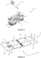
- the stabilization device 5 comprises a main frame 50 defining a horizontal plane PH, an auxiliary frame 51 mounted in said main frame 50, a ballast 52 mounted in said auxiliary frame 51 and displacement means configured to move the ballast 52 in said horizontal plane PH.
- the stabilization device 5 further comprises a control module (not shown) configured to modify the position of the ballast 52 in said horizontal plane PH as a function of the position of the distal end of the working member 4 in order to increase the stability of the working machine 1.
- the main frame 50 defining a horizontal plane PH.
- the main frame 50 has in this example a rectangular shape and comprises two longitudinal side members 501 extending along an X axis and two lateral side members 502 extending along a Y axis.
- the X, Y axes are orthogonal and define the horizontal plane PH .
- the main frame 50 further comprises two stop side members 503 which extend parallel to the side side members 502 and are located between them.
- the auxiliary frame 51 is adapted to move longitudinally along the X axis in the space defined between the longitudinal side members 501 and the stop side members 503.
- the longitudinal side members 501 of the auxiliary frame 50 are adapted to guide the auxiliary frame 51 according to the X axis and to prevent any movement along the Y axis.
- the auxiliary frame 51 Analogously to the main frame 50, the auxiliary frame 51 has in this example a rectangular shape and comprises two longitudinal longitudinal members 511 extending along an axis X and two lateral longitudinal members 512 extending along an axis Y.
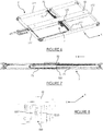
- the auxiliary frame 51 further comprises a guide spar 513 which extends parallel to the side spars 512 and is located between them. As shown in figure 4 , each side face of the guide spar 513 comprises a guide rail 516.
- the side members of the main frame 50 and of the auxiliary frame 51 are preferably made of metal, but it goes without saying that other materials could be suitable, in particular, composite materials.
- the main frame 50 has a length of the order of 9m and a width of the order of 3m.
- the auxiliary frame 51 has, for its part, a length of the order of 7 m and a width of the order of 2.8 m.
- the stabilization device 5 comprises first displacement means 6 configured to move in a motorized manner the auxiliary frame 51 relative to the main frame 50.
- the first displacement means 6 are configured to carry out a displacement along the line. 'longitudinal axis X and are connected between a side spar 502 of the main frame 50 and a side spar 512 of the auxiliary frame 51 as illustrated in figure 3 .
- the lateral stop spar 503, located on the passage of the first displacement means 6, comprises an opening 506 in which extend the said first displacement means 6 as illustrated in figure 3 .
- the first displacement means 6 comprise a jack 61, preferably double-acting, and a chain 62.
- a jack 61 preferably double-acting
- a chain 62 preferably double-acting
- the cylinder 61 is configured to provide a thrust of at least 770 kg.
- the moving speed of the auxiliary frame 51 can reach 0.3 m / s.
- each longitudinal spar 511 of the auxiliary frame 51 comprises two guide rollers 515 which cooperate with a rail supported by a longitudinal spar 501 of the main frame 50.
- other guide means along the longitudinal axis X might be suitable.
- the first displacement means 6 extend in the horizontal plane PH in order to limit the bulk and limit the mechanical and dynamic stresses.
- the ballast 52 is in the form of a parallelepiped extending longitudinally along the X axis and laterally along the Y axis.
- the length of the ballast 52 is between 200 cm and 400 cm, its width is between 100 cm and 280 cm and its thickness is between 5 cm and 100 cm.
- the ballast 52 has a mass of between 1 t and 4 t, in particular 2.6 tonnes, and is preferably made from a material having a high density, in particular steel.
- the ballast 52 has a through opening 520 extending along the Y axis so as to allow support of the ballast 52 by the guide spar 513 of the auxiliary frame 51.
- the ballast 52 is guided at the ends by the side spars 512 and by the guide spar 513. It goes without saying that several guide spars 513 could be provided to support the ballast 52.
- the ballast 52 comprises two guide rollers 525 ( Figure 8 ) which cooperate with rails supported by the side members 512, 513 of the auxiliary frame 51.
- the ballast 52 comprises two pairs of guide rollers 525 to cooperate with two guide rails 516 supported by the lateral guide spar 513 of the auxiliary frame 51.
- the ballast 52 is supported and optimally guided by the lateral guide spar 513.
- other guide means along the longitudinal axis Y could be suitable.
- the stabilization device 5 comprises second displacement means 7 configured to move the ballast 52 in a motorized manner relative to the auxiliary frame 51.
- the second displacement means 7 are configured to carry out a displacement according to the lateral axis Y and are connected between the longitudinal side members 511 of the auxiliary frame 51 as shown in figure 6 .
- the second displacement means 7 comprise two jacks 71, preferably double-acting, and a chain 72.
- the displacement speed of the ballast 52 can reach 0.3 m / s.
- the second displacement means 7 extend in the horizontal plane PH in order to limit the bulk and limit the mechanical and dynamic stresses.
- the stabilization device 5 further comprises a control module (not shown) adapted to control the movement of the ballast 52 in the main frame 50.
- the control module is connected, on the one hand, to the first displacement means 6 to allow displacement along the longitudinal axis X and, on the other hand, to the second displacement means 7 to allow displacement along the lateral axis Y.
- the control module is connected to means for measuring the position of the distal end of the working member 4 with respect to the frame 2.
- each working member 4 is telescopic and is equipped with angular sensors. Also, the position of the distal end is obtained by measuring the telescoped length and by measuring the angular values of inclination in a horizontal and vertical frame of reference. In this example, each working member 4 is telescopic by means of a cable associated with a reel. The telescoped length is measured through the reel which provides the length of cable unwound at a given time.
- the control module is connected to means for measuring the stability of the vehicle.
- the control module is connected to means for measuring the inclination of the frame 2 relative to a horizontal reference plane which is independent of the machine 1.
- Such a measurement makes it possible to provide additional information for controlling the frame. ballast and thus limit the risk of tilting of the chassis 2.
- the control module is connected to means for measuring the mechanical forces applied to the shod wheels of the chassis 2. In fact, the less the mechanical forces, the greater the risk. rollover rate is high.
- the control module determines a displacement of the ballast in order to increase the measurement of stability of said machine 1.
- the Command parameters can be entered in a command table or obtained by self-learning.
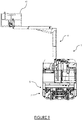
- the machine 1 comprises a frame 2 and two working members 4 each comprising, at a distal end, a nacelle 41 adapted to accommodate operators (a single nacelle 41 shown in figure 9 ).
- Each nacelle 41 can accommodate a mass of 300kg and is able to be moved up to 9.5 meters in height and up to 4 meters lateral offset.
- the machine 1 further comprises a working member 4 fulfilling a crane function and which is suitable for carrying a load of 150 kg up to 8.5 meters in height and up to 4 meters of lateral offset.
- the machine 1 further comprises a skidding mat (not shown) having a thrust capacity of 500 kg.
- Such a machine 1 is thus configured to perform heterogeneous tasks in the same railway area.
- the stabilization module 5 makes it possible to avoid any overturning, even for large offsets.
- the method comprises a step of measuring the position of the distal end of the working member 4 with respect to the frame 2.
- the method then comprises a step of determining, by the control module, a position of the ballast 52 in the horizontal plane PH which improves the stability.
- the method comprises a step of moving the ballast 52, by the movement means 6, 7, to the determined position.
- the stabilization method is implemented in real time to ensure dynamic balancing ensuring stability.
- the nacelle 41 is shown in maximum lateral offset to the left with the ballast 52 positioned to the right to guarantee stability.
- the chassis 2 is stabilized during an offset forward (stabilizing moment in front offset 0.3 tm), rearward (stabilizing moment in rear offset 2.6 tm) or lateral (stabilizing moment in front offset 2 , 9 tm).
- a work machine 1 can be stabilized internally without resorting to means increasing its size. Also, advantageously, the vehicle can remain within the rail gauge to carry out maintenance steps, which makes it possible to authorize operation of the adjacent rail tracks.
Landscapes
- Engineering & Computer Science (AREA)
- Structural Engineering (AREA)
- Mechanical Engineering (AREA)
- Life Sciences & Earth Sciences (AREA)
- Geology (AREA)
- Machines For Laying And Maintaining Railways (AREA)
- Agricultural Machines (AREA)
Claims (10)
- Gerät zum Arbeiten in der Höhe (1), umfassend ein Gestell (2), mindestens ein Organ zur Verlagerung auf dem Boden (3), das mit dem Gestell (2) verbunden ist, und mindestens ein Arbeitsorgan (4), umfassend ein proximales Ende (40), das mit dem Gestell (2) verbunden ist, und ein distales Ende, das geeignet ist, sich in der Höhe von dem Gestell (2) beabstandet zu erstrecken, wobei das Gerät dadurch gekennzeichnet ist, dass das Gestell (2) mindestens eine Stabilisierungsvorrichtung (5) aufweist, die einen Hauptrahmen (50) aufweist, der eine horizontale Ebene (PH) festlegt, einen Ballast (52), Verlagerungsmittel (6, 7) des Ballasts (52) in der horizontalen Ebene (PH) und Steuermittel, die ausgelegt sind, um den Ballast (52) in der horizontalen Ebene (PH) im Hauptrahmen (50) in Abhängigkeit von der Position des distalen Endes des Arbeitsorgans (4) zu verlagern, um die Stabilität des Arbeitsgeräts (1) zu erhöhen.
- Gerät nach Anspruch 1, wobei die Verlagerungsmittel erste Verlagerungsmittel (6) gemäß einer Längsachse (X) und zweite Verlagerungsmittel (7) gemäß einer Seitenachse (Y) umfassen.
- Gerät nach einem der Ansprüche 1 bis 2, wobei die Verlagerungsmittel (6, 7) ausgelegt sind, um den Ballast (52) gemäß einer Längsachse (X) über eine Entfernung zu verlagern, die zwischen 50 cm und 90 cm liegt, und gemäß einer Seitenachse (Y) über eine Entfernung, die zwischen 1100 cm und 2200 cm liegt.
- Gerät nach einem der Ansprüche 1 bis 3, wobei der Ballast (52) eine Masse besitzt, die zwischen 1 t und 4 t liegt.
- Gerät nach einem der Ansprüche 1 bis 4, wobei sich der Ballast (52) gemäß der Länge des Gestells (2) erstreckt.
- Gerät nach einem der Ansprüche 1 bis 5, wobei der Ballast (52) eine Länge besitzt, die zwischen 200 cm und 400 cm liegt.
- Gerät nach einem der Ansprüche 1 bis 6, wobei die Stabilisierungsvorrichtung (5) einen Hilfsrahmen (51) aufweist, der beweglich im Hauptrahmen (50) angebracht ist, wobei der Ballast (52) beweglich im Hilfsrahmen (51) angebracht ist.
- Gerät nach Anspruch 7, wobei die Verlagerungsmittel erste Verlagerungsmittel (6) des Hilfsrahmens (51) im Hauptrahmen (50) gemäß einer Längsachse (X) und zweite Verlagerungsmittel (7) des Ballasts (52) im Hilfsrahmen (51) gemäß einer Seitenachse (Y) umfassen.
- Gerät nach einem der Ansprüche 7 bis 8, wobei die Stabilisierungsvorrichtung (5) einen Führungsträger (513) aufweist, der sich in einer Durchgangsöffnung (520) des Ballasts (52) erstreckt, um ihn zu führen.
- Verfahren zur Stabilisierung eines Geräts zum Arbeiten in der Höhe nach einem der Ansprüche 1 bis 9, wobei das Verfahren umfasst:a. einen Schritt des Messens der Position des distalen Endes des Arbeitsorgans (4) in Bezug auf das Gestell (2),b. einen Schritt des Bestimmens, durch das Steuermodul, einer Position des Ballasts (52) in der horizontalen Ebene (PH), die die la Stabilität verbessert, undc. einen Schritt des Verlagerns des Ballasts (52), durch die Verlagerungsmittel (6, 7), in die bestimmte Position im Hauptrahmen (50).
Applications Claiming Priority (1)
| Application Number | Priority Date | Filing Date | Title |
|---|---|---|---|
| FR1760458A FR3073216B1 (fr) | 2017-11-07 | 2017-11-07 | Engin de travail en hauteur et methode de stabilisation d'un tel engin |
Publications (2)
| Publication Number | Publication Date |
|---|---|
| EP3480159A1 EP3480159A1 (de) | 2019-05-08 |
| EP3480159B1 true EP3480159B1 (de) | 2021-09-08 |
Family
ID=61003170
Family Applications (1)
| Application Number | Title | Priority Date | Filing Date |
|---|---|---|---|
| EP18204611.0A Active EP3480159B1 (de) | 2017-11-07 | 2018-11-06 | Gerät zum arbeiten in der höhe und stabilisierungsmethode eines solchen geräts |
Country Status (2)
| Country | Link |
|---|---|
| EP (1) | EP3480159B1 (de) |
| FR (1) | FR3073216B1 (de) |
Families Citing this family (2)
| Publication number | Priority date | Publication date | Assignee | Title |
|---|---|---|---|---|
| CN111847282A (zh) * | 2020-09-04 | 2020-10-30 | 浙江三一装备有限公司 | 一种限位支架及起重机 |
| CN113276896B (zh) * | 2021-06-08 | 2023-01-06 | 中国铁建电气化局集团有限公司 | 一种接触网上部结构智能安装设备 |
Family Cites Families (2)
| Publication number | Priority date | Publication date | Assignee | Title |
|---|---|---|---|---|
| US8602153B2 (en) * | 2007-08-06 | 2013-12-10 | Extendquip Llc | Extendable frame work vehicle |
| DE102016106432B4 (de) * | 2016-04-08 | 2017-12-28 | Bernhard Hunklinger | Arbeitsmaschine in Form eines Baggers oder Krans |
-
2017
- 2017-11-07 FR FR1760458A patent/FR3073216B1/fr active Active
-
2018
- 2018-11-06 EP EP18204611.0A patent/EP3480159B1/de active Active
Also Published As
| Publication number | Publication date |
|---|---|
| FR3073216B1 (fr) | 2020-07-17 |
| EP3480159A1 (de) | 2019-05-08 |
| FR3073216A1 (fr) | 2019-05-10 |
Similar Documents
| Publication | Publication Date | Title |
|---|---|---|
| EP2699445B1 (de) | Scherenstromabnehmer für ein schienenfahrzeug | |
| EP0233098B1 (de) | Verladevorrichtung zum Laden, insbesondere zum schnellen Transferieren von palettierten Lasten | |
| EP3480159A1 (de) | Gerät zum arbeiten in der höhe und stabilisierungsmethode eines solchen geräts | |
| WO2006120363A1 (fr) | Dispositif d'élinguage d'une pièce avec compensation d'effort et système de levage le comprenant | |
| EP1157950A1 (de) | Vorrichtung zum Fördern von massiven Gegenständen, insbesondere Metallspulen | |
| FR3068343A1 (fr) | Portique de manutention et systeme de manutention comprenant un tel portique | |
| FR2956106A1 (fr) | Vehicule elevateur pour le positionnement d'une charge en hauteur | |
| EP3556635A1 (de) | Schienenfahrzeug und entsprechendes verkehrsverfahren | |
| EP2905195B1 (de) | Mobile messvorrichtung für ein schienenkopfprofil | |
| EP1818453A1 (de) | Verfahren und Vorrichtung zum Einsetzen von Elementen in die Erde, Mechanismus für diese Vorrichtung und dieses Verfahren nutzendes System | |
| EP2993264A1 (de) | Angepasster strukturträger zum tragen einer ausrüstung | |
| EP2993266B1 (de) | System und verfahren zum transport einer ausrüstung | |
| EP0100926A1 (de) | Fahrzeug zur Handhabung von Materialien mit orientierbarem Ausleger und eingebautem Stabilisiergestell | |
| WO2014001393A1 (fr) | Dispositif pour la manutention de conteneurs sous caténaires ferroviaires | |
| EP2789963B1 (de) | Halterungsvorrichtung einer Waffenstation | |
| EP3852968A1 (de) | System zum ausrichten von schienenabschnitten für eine induktionsschweisseinheit | |
| FR2876993A1 (fr) | Dispositif pour positionner simultanement au moins un operateur et des elements de construction et procede de montage utilisant un tel dispositif. | |
| EP1599408A1 (de) | Gabelstapler für reifen | |
| FR2652836A1 (fr) | Dispositif pour soulever et deplacer des objets et procede pour sa mise en óoeuvre. | |
| FR2490166A1 (fr) | Vehicule equipe de dispositifs de transbordement lateral de conteneurs | |
| EP3300933B1 (de) | Schienen-/strassenfahrzeug zum verlegen einer oberleitung | |
| EP3031984A1 (de) | Wagen, der auf einem weg parallel zu einer wand geführt werden kann | |
| EP2910513A1 (de) | Hebevorrichtung mit einer Regulierung der Höhenlage | |
| EP3640111B1 (de) | Wagen und einheit, die ein fahrzeug und einen solchen wagen umfasst | |
| WO2024261085A1 (fr) | Procédé de commande d'une nacelle élévatrice, notamment une nacelle ciseaux, et nacelle élévatrice associée |
Legal Events
| Date | Code | Title | Description |
|---|---|---|---|
| PUAI | Public reference made under article 153(3) epc to a published international application that has entered the european phase |
Free format text: ORIGINAL CODE: 0009012 |
|
| STAA | Information on the status of an ep patent application or granted ep patent |
Free format text: STATUS: THE APPLICATION HAS BEEN PUBLISHED |
|
| AK | Designated contracting states |
Kind code of ref document: A1 Designated state(s): AL AT BE BG CH CY CZ DE DK EE ES FI FR GB GR HR HU IE IS IT LI LT LU LV MC MK MT NL NO PL PT RO RS SE SI SK SM TR |
|
| AX | Request for extension of the european patent |
Extension state: BA ME |
|
| STAA | Information on the status of an ep patent application or granted ep patent |
Free format text: STATUS: REQUEST FOR EXAMINATION WAS MADE |
|
| 17P | Request for examination filed |
Effective date: 20191018 |
|
| RBV | Designated contracting states (corrected) |
Designated state(s): AL AT BE BG CH CY CZ DE DK EE ES FI FR GB GR HR HU IE IS IT LI LT LU LV MC MK MT NL NO PL PT RO RS SE SI SK SM TR |
|
| GRAP | Despatch of communication of intention to grant a patent |
Free format text: ORIGINAL CODE: EPIDOSNIGR1 |
|
| STAA | Information on the status of an ep patent application or granted ep patent |
Free format text: STATUS: GRANT OF PATENT IS INTENDED |
|
| INTG | Intention to grant announced |
Effective date: 20210401 |
|
| GRAS | Grant fee paid |
Free format text: ORIGINAL CODE: EPIDOSNIGR3 |
|
| GRAA | (expected) grant |
Free format text: ORIGINAL CODE: 0009210 |
|
| STAA | Information on the status of an ep patent application or granted ep patent |
Free format text: STATUS: THE PATENT HAS BEEN GRANTED |
|
| AK | Designated contracting states |
Kind code of ref document: B1 Designated state(s): AL AT BE BG CH CY CZ DE DK EE ES FI FR GB GR HR HU IE IS IT LI LT LU LV MC MK MT NL NO PL PT RO RS SE SI SK SM TR |
|
| REG | Reference to a national code |
Ref country code: GB Ref legal event code: FG4D Free format text: NOT ENGLISH |
|
| REG | Reference to a national code |
Ref country code: CH Ref legal event code: EP Ref country code: AT Ref legal event code: REF Ref document number: 1428432 Country of ref document: AT Kind code of ref document: T Effective date: 20210915 |
|
| REG | Reference to a national code |
Ref country code: DE Ref legal event code: R096 Ref document number: 602018023171 Country of ref document: DE |
|
| REG | Reference to a national code |
Ref country code: IE Ref legal event code: FG4D Free format text: LANGUAGE OF EP DOCUMENT: FRENCH |
|
| REG | Reference to a national code |
Ref country code: LT Ref legal event code: MG9D |
|
| REG | Reference to a national code |
Ref country code: NL Ref legal event code: MP Effective date: 20210908 |
|
| PG25 | Lapsed in a contracting state [announced via postgrant information from national office to epo] |
Ref country code: SE Free format text: LAPSE BECAUSE OF FAILURE TO SUBMIT A TRANSLATION OF THE DESCRIPTION OR TO PAY THE FEE WITHIN THE PRESCRIBED TIME-LIMIT Effective date: 20210908 Ref country code: RS Free format text: LAPSE BECAUSE OF FAILURE TO SUBMIT A TRANSLATION OF THE DESCRIPTION OR TO PAY THE FEE WITHIN THE PRESCRIBED TIME-LIMIT Effective date: 20210908 Ref country code: HR Free format text: LAPSE BECAUSE OF FAILURE TO SUBMIT A TRANSLATION OF THE DESCRIPTION OR TO PAY THE FEE WITHIN THE PRESCRIBED TIME-LIMIT Effective date: 20210908 Ref country code: ES Free format text: LAPSE BECAUSE OF FAILURE TO SUBMIT A TRANSLATION OF THE DESCRIPTION OR TO PAY THE FEE WITHIN THE PRESCRIBED TIME-LIMIT Effective date: 20210908 Ref country code: FI Free format text: LAPSE BECAUSE OF FAILURE TO SUBMIT A TRANSLATION OF THE DESCRIPTION OR TO PAY THE FEE WITHIN THE PRESCRIBED TIME-LIMIT Effective date: 20210908 Ref country code: NO Free format text: LAPSE BECAUSE OF FAILURE TO SUBMIT A TRANSLATION OF THE DESCRIPTION OR TO PAY THE FEE WITHIN THE PRESCRIBED TIME-LIMIT Effective date: 20211208 Ref country code: BG Free format text: LAPSE BECAUSE OF FAILURE TO SUBMIT A TRANSLATION OF THE DESCRIPTION OR TO PAY THE FEE WITHIN THE PRESCRIBED TIME-LIMIT Effective date: 20211208 Ref country code: LT Free format text: LAPSE BECAUSE OF FAILURE TO SUBMIT A TRANSLATION OF THE DESCRIPTION OR TO PAY THE FEE WITHIN THE PRESCRIBED TIME-LIMIT Effective date: 20210908 |
|
| REG | Reference to a national code |
Ref country code: AT Ref legal event code: MK05 Ref document number: 1428432 Country of ref document: AT Kind code of ref document: T Effective date: 20210908 |
|
| PG25 | Lapsed in a contracting state [announced via postgrant information from national office to epo] |
Ref country code: LV Free format text: LAPSE BECAUSE OF FAILURE TO SUBMIT A TRANSLATION OF THE DESCRIPTION OR TO PAY THE FEE WITHIN THE PRESCRIBED TIME-LIMIT Effective date: 20210908 Ref country code: GR Free format text: LAPSE BECAUSE OF FAILURE TO SUBMIT A TRANSLATION OF THE DESCRIPTION OR TO PAY THE FEE WITHIN THE PRESCRIBED TIME-LIMIT Effective date: 20211209 |
|
| PG25 | Lapsed in a contracting state [announced via postgrant information from national office to epo] |
Ref country code: AT Free format text: LAPSE BECAUSE OF FAILURE TO SUBMIT A TRANSLATION OF THE DESCRIPTION OR TO PAY THE FEE WITHIN THE PRESCRIBED TIME-LIMIT Effective date: 20210908 |
|
| PG25 | Lapsed in a contracting state [announced via postgrant information from national office to epo] |
Ref country code: IS Free format text: LAPSE BECAUSE OF FAILURE TO SUBMIT A TRANSLATION OF THE DESCRIPTION OR TO PAY THE FEE WITHIN THE PRESCRIBED TIME-LIMIT Effective date: 20220108 Ref country code: SM Free format text: LAPSE BECAUSE OF FAILURE TO SUBMIT A TRANSLATION OF THE DESCRIPTION OR TO PAY THE FEE WITHIN THE PRESCRIBED TIME-LIMIT Effective date: 20210908 Ref country code: SK Free format text: LAPSE BECAUSE OF FAILURE TO SUBMIT A TRANSLATION OF THE DESCRIPTION OR TO PAY THE FEE WITHIN THE PRESCRIBED TIME-LIMIT Effective date: 20210908 Ref country code: RO Free format text: LAPSE BECAUSE OF FAILURE TO SUBMIT A TRANSLATION OF THE DESCRIPTION OR TO PAY THE FEE WITHIN THE PRESCRIBED TIME-LIMIT Effective date: 20210908 Ref country code: PT Free format text: LAPSE BECAUSE OF FAILURE TO SUBMIT A TRANSLATION OF THE DESCRIPTION OR TO PAY THE FEE WITHIN THE PRESCRIBED TIME-LIMIT Effective date: 20220110 Ref country code: PL Free format text: LAPSE BECAUSE OF FAILURE TO SUBMIT A TRANSLATION OF THE DESCRIPTION OR TO PAY THE FEE WITHIN THE PRESCRIBED TIME-LIMIT Effective date: 20210908 Ref country code: NL Free format text: LAPSE BECAUSE OF FAILURE TO SUBMIT A TRANSLATION OF THE DESCRIPTION OR TO PAY THE FEE WITHIN THE PRESCRIBED TIME-LIMIT Effective date: 20210908 Ref country code: EE Free format text: LAPSE BECAUSE OF FAILURE TO SUBMIT A TRANSLATION OF THE DESCRIPTION OR TO PAY THE FEE WITHIN THE PRESCRIBED TIME-LIMIT Effective date: 20210908 Ref country code: CZ Free format text: LAPSE BECAUSE OF FAILURE TO SUBMIT A TRANSLATION OF THE DESCRIPTION OR TO PAY THE FEE WITHIN THE PRESCRIBED TIME-LIMIT Effective date: 20210908 Ref country code: AL Free format text: LAPSE BECAUSE OF FAILURE TO SUBMIT A TRANSLATION OF THE DESCRIPTION OR TO PAY THE FEE WITHIN THE PRESCRIBED TIME-LIMIT Effective date: 20210908 |
|
| REG | Reference to a national code |
Ref country code: DE Ref legal event code: R119 Ref document number: 602018023171 Country of ref document: DE |
|
| PG25 | Lapsed in a contracting state [announced via postgrant information from national office to epo] |
Ref country code: MC Free format text: LAPSE BECAUSE OF FAILURE TO SUBMIT A TRANSLATION OF THE DESCRIPTION OR TO PAY THE FEE WITHIN THE PRESCRIBED TIME-LIMIT Effective date: 20210908 |
|
| REG | Reference to a national code |
Ref country code: CH Ref legal event code: PL |
|
| PLBE | No opposition filed within time limit |
Free format text: ORIGINAL CODE: 0009261 |
|
| STAA | Information on the status of an ep patent application or granted ep patent |
Free format text: STATUS: NO OPPOSITION FILED WITHIN TIME LIMIT |
|
| PG25 | Lapsed in a contracting state [announced via postgrant information from national office to epo] |
Ref country code: LU Free format text: LAPSE BECAUSE OF NON-PAYMENT OF DUE FEES Effective date: 20211106 Ref country code: DK Free format text: LAPSE BECAUSE OF FAILURE TO SUBMIT A TRANSLATION OF THE DESCRIPTION OR TO PAY THE FEE WITHIN THE PRESCRIBED TIME-LIMIT Effective date: 20210908 Ref country code: BE Free format text: LAPSE BECAUSE OF NON-PAYMENT OF DUE FEES Effective date: 20211130 |
|
| REG | Reference to a national code |
Ref country code: BE Ref legal event code: MM Effective date: 20211130 |
|
| 26N | No opposition filed |
Effective date: 20220609 |
|
| PG25 | Lapsed in a contracting state [announced via postgrant information from national office to epo] |
Ref country code: SI Free format text: LAPSE BECAUSE OF FAILURE TO SUBMIT A TRANSLATION OF THE DESCRIPTION OR TO PAY THE FEE WITHIN THE PRESCRIBED TIME-LIMIT Effective date: 20210908 |
|
| PG25 | Lapsed in a contracting state [announced via postgrant information from national office to epo] |
Ref country code: IE Free format text: LAPSE BECAUSE OF NON-PAYMENT OF DUE FEES Effective date: 20211106 Ref country code: DE Free format text: LAPSE BECAUSE OF NON-PAYMENT OF DUE FEES Effective date: 20220601 |
|
| PG25 | Lapsed in a contracting state [announced via postgrant information from national office to epo] |
Ref country code: IT Free format text: LAPSE BECAUSE OF FAILURE TO SUBMIT A TRANSLATION OF THE DESCRIPTION OR TO PAY THE FEE WITHIN THE PRESCRIBED TIME-LIMIT Effective date: 20210908 |
|
| PG25 | Lapsed in a contracting state [announced via postgrant information from national office to epo] |
Ref country code: CY Free format text: LAPSE BECAUSE OF FAILURE TO SUBMIT A TRANSLATION OF THE DESCRIPTION OR TO PAY THE FEE WITHIN THE PRESCRIBED TIME-LIMIT Effective date: 20210908 |
|
| GBPC | Gb: european patent ceased through non-payment of renewal fee |
Effective date: 20221106 |
|
| PG25 | Lapsed in a contracting state [announced via postgrant information from national office to epo] |
Ref country code: LI Free format text: LAPSE BECAUSE OF NON-PAYMENT OF DUE FEES Effective date: 20220630 Ref country code: HU Free format text: LAPSE BECAUSE OF FAILURE TO SUBMIT A TRANSLATION OF THE DESCRIPTION OR TO PAY THE FEE WITHIN THE PRESCRIBED TIME-LIMIT; INVALID AB INITIO Effective date: 20181106 Ref country code: CH Free format text: LAPSE BECAUSE OF NON-PAYMENT OF DUE FEES Effective date: 20220630 |
|
| PG25 | Lapsed in a contracting state [announced via postgrant information from national office to epo] |
Ref country code: GB Free format text: LAPSE BECAUSE OF NON-PAYMENT OF DUE FEES Effective date: 20221106 |
|
| PG25 | Lapsed in a contracting state [announced via postgrant information from national office to epo] |
Ref country code: MK Free format text: LAPSE BECAUSE OF FAILURE TO SUBMIT A TRANSLATION OF THE DESCRIPTION OR TO PAY THE FEE WITHIN THE PRESCRIBED TIME-LIMIT Effective date: 20210908 |
|
| PG25 | Lapsed in a contracting state [announced via postgrant information from national office to epo] |
Ref country code: TR Free format text: LAPSE BECAUSE OF FAILURE TO SUBMIT A TRANSLATION OF THE DESCRIPTION OR TO PAY THE FEE WITHIN THE PRESCRIBED TIME-LIMIT Effective date: 20210908 |
|
| PG25 | Lapsed in a contracting state [announced via postgrant information from national office to epo] |
Ref country code: MT Free format text: LAPSE BECAUSE OF FAILURE TO SUBMIT A TRANSLATION OF THE DESCRIPTION OR TO PAY THE FEE WITHIN THE PRESCRIBED TIME-LIMIT Effective date: 20210908 |
|
| PGFP | Annual fee paid to national office [announced via postgrant information from national office to epo] |
Ref country code: FR Payment date: 20251127 Year of fee payment: 8 |