EP3480831A1 - Actionneur, dispositif de déclenchement à distance, ensemble de régulateur et ascenseur - Google Patents
Actionneur, dispositif de déclenchement à distance, ensemble de régulateur et ascenseur Download PDFInfo
- Publication number
- EP3480831A1 EP3480831A1 EP18205706.7A EP18205706A EP3480831A1 EP 3480831 A1 EP3480831 A1 EP 3480831A1 EP 18205706 A EP18205706 A EP 18205706A EP 3480831 A1 EP3480831 A1 EP 3480831A1
- Authority
- EP
- European Patent Office
- Prior art keywords
- mandrel
- actuator
- sliding member
- sleeve
- contact plate
- Prior art date
- Legal status (The legal status is an assumption and is not a legal conclusion. Google has not performed a legal analysis and makes no representation as to the accuracy of the status listed.)
- Granted
Links
Images

Classifications
-
- B—PERFORMING OPERATIONS; TRANSPORTING
- B66—HOISTING; LIFTING; HAULING
- B66B—ELEVATORS; ESCALATORS OR MOVING WALKWAYS
- B66B5/00—Applications of checking, fault-correcting, or safety devices in elevators
- B66B5/02—Applications of checking, fault-correcting, or safety devices in elevators responsive to abnormal operating conditions
- B66B5/04—Applications of checking, fault-correcting, or safety devices in elevators responsive to abnormal operating conditions for detecting excessive speed
- B66B5/048—Testing of overspeed governor
-
- B—PERFORMING OPERATIONS; TRANSPORTING
- B66—HOISTING; LIFTING; HAULING
- B66B—ELEVATORS; ESCALATORS OR MOVING WALKWAYS
- B66B5/00—Applications of checking, fault-correcting, or safety devices in elevators
- B66B5/02—Applications of checking, fault-correcting, or safety devices in elevators responsive to abnormal operating conditions
- B66B5/04—Applications of checking, fault-correcting, or safety devices in elevators responsive to abnormal operating conditions for detecting excessive speed
- B66B5/044—Mechanical overspeed governors
-
- H—ELECTRICITY
- H01—ELECTRIC ELEMENTS
- H01F—MAGNETS; INDUCTANCES; TRANSFORMERS; SELECTION OF MATERIALS FOR THEIR MAGNETIC PROPERTIES
- H01F7/00—Magnets
- H01F7/06—Electromagnets; Actuators including electromagnets
- H01F7/08—Electromagnets; Actuators including electromagnets with armatures
- H01F7/121—Guiding or setting position of armatures, e.g. retaining armatures in their end position
- H01F7/123—Guiding or setting position of armatures, e.g. retaining armatures in their end position by ancillary coil
-
- H—ELECTRICITY
- H01—ELECTRIC ELEMENTS
- H01F—MAGNETS; INDUCTANCES; TRANSFORMERS; SELECTION OF MATERIALS FOR THEIR MAGNETIC PROPERTIES
- H01F7/00—Magnets
- H01F7/06—Electromagnets; Actuators including electromagnets
- H01F7/08—Electromagnets; Actuators including electromagnets with armatures
- H01F7/121—Guiding or setting position of armatures, e.g. retaining armatures in their end position
- H01F7/124—Guiding or setting position of armatures, e.g. retaining armatures in their end position by mechanical latch, e.g. detent
-
- H—ELECTRICITY
- H01—ELECTRIC ELEMENTS
- H01F—MAGNETS; INDUCTANCES; TRANSFORMERS; SELECTION OF MATERIALS FOR THEIR MAGNETIC PROPERTIES
- H01F7/00—Magnets
- H01F7/06—Electromagnets; Actuators including electromagnets
- H01F7/08—Electromagnets; Actuators including electromagnets with armatures
- H01F7/16—Rectilinearly-movable armatures
- H01F7/1607—Armatures entering the winding
Definitions
- the present invention relates to the related field of actuators, and in particular, the present invention relates to a self-locking actuator and an application of the actuator in the field of elevators.
- the governor assembly when a rotating speed of a sheave exceeds a certain value, a centrifugal mechanism that rotates together with the sheave is triggered such that the sheave drives a core ring related to a safety apparatus to rotate, thereby triggering the governor assembly, including triggering a safety switch to stop supplying power and enabling the safety apparatus to generate mechanical friction with a channel to brake a car.
- the patent is incorporated here by reference in its entirety.
- the governor assembly further includes a remote triggering apparatus.
- the remote triggering apparatus can be controlled actively to act on the centrifugal mechanism, such that the governor assembly can be triggered actively even that the car is not stalled, so as to achieve an objective such as testing.
- the existing remote triggering apparatus is mainly composed of an electromagnet, and a tail end of a column of the electromagnet directly acts on the centrifugal mechanism that is generally made of plastic.
- the Chinese Utility Model Patent No. ZL201621141734.2 submitted by the Otis Elevator Company on October 20, 2016 and entitled "REMOTE TRIGGERING APPARATUS, GOVERNOR ASSEMBLY, AND ELEVATOR" has disclosed a remote triggering apparatus. A contact having a smooth transition surface is adopted in the remote triggering apparatus, for attempting to apply the CMG to a high-speed elevator.
- the patent is incorporated here by reference in its entirety.
- the present invention is aimed at solving or at least alleviating the problems in the prior art.
- the present invention is aimed at providing an actuator that is self-locked at an actuation position, to prevent the actuator from retracting after being impacted.
- the present invention is aimed at preventing a mandrel of the actuator from being impacted.
- the present invention is aimed at lowering the requirements for electromagnetic forces of the actuator, thereby lowering the requirements for the actuator.
- the present invention is aimed at improving the reliability of a remote triggering apparatus, a governor, and an elevator.
- An actuator including: a mandrel, the mandrel having a proximal end and a distal end, the mandrel being driven to move from a contraction position toward an actuation position; a mandrel sleeve, the mandrel sleeve being sleeved on the distal end of the mandrel; and a shell, the shell defining a channel, wherein the actuator further includes at least one sliding member, and when the mandrel moves from the contraction position toward the actuation position, the at least one sliding member is located at a first radial position where the mandrel is joined to the mandrel sleeve, such that the mandrel sleeve can move along the channel together with the mandrel; and wherein at the actuation position, the at least one sliding member moves outward radially to a second radial position where the mandrel sleeve is joined to the shell, thus locking the mandrel
- the mandrel may comprises a slope, the slope acting on the at least one sliding member and applying a radially outward component force to the at least one sliding member.
- the radially outward component force may urge the at least one sliding member to move from the first radial position to the second radial position.
- the at least one sliding member may be spherical, cylindrical, or ellipsoidal.
- the mandrel may be driven by an electromagnetic driving apparatus.
- the at least one sliding member may comprises a pair of opposite sliding members or more sliding members that are distributed uniformly along the periphery of the mandrel.
- the mandrel may have a groove
- the mandrel sleeve may have at least one opening of which the number and position correspond to those of the sliding members
- the at least one sliding member may be located at the first radial position between the groove of the mandrel and the at least one opening of the mandrel sleeve.
- One side of the groove of the mandrel close to the proximal end may define a slope, and the slope may act on the at least one sliding member and apply a radially outward component force to the at least one sliding member.
- the mandrel may comprise a mandrel body, a mandrel contraction part, and a slope between the mandrel body and the mandrel contraction part.
- the mandrel further may comprises a cap covering a tail end of the mandrel contraction part, and the slope, the mandrel contraction part, and the cap jointly may define the groove on the mandrel.
- a recessed part may be provided on an inner side of the channel of the shell, the recessed part may be located at a radial outer side of the at least one sliding member at the actuation position, and at the actuation position, the at least one sliding member may be pushed out by the mandrel and move to the second radial position between the recessed part of the shell and the opening of the mandrel sleeve.
- the recessed part may be spherical.
- the recessed part may have a first portion close to the proximal end and a second portion close to the distal end, the first portion of the recessed part may have a slope angle less than 45 degrees, or the first portion of the recessed part may have a slope angle less than that of the second portion of the recessed part.
- the mandrel may be decoupled from the mandrel sleeve, and the mandrel may be driven to further move forward with respect to the mandrel sleeve in the mandrel sleeve, a side wall of the mandrel limiting the at least one sliding member to the second radial position.
- a first reset spring may be disposed between the mandrel and the mandrel sleeve.
- a rear end of the mandrel may have a boss, and a second reset spring may be disposed between the boss at the rear end of the mandrel and an inner side of the actuator.
- the mandrel may comprise a mandrel stick located at the proximal end and a mandrel rod located at the distal end and connected to the mandrel stick.
- a coil may be arranged at the periphery of the mandrel stick, and the mandrel stick may be made of a magnetic material and may be driven by a magnetic field generated after the coil is powered on.
- the shell may constitute an actuator front cover
- the actuator front cover may comprise a flat part and a cylindrical part protruded from the flat part, and the cylindrical part may define at least a part of the channel.
- the actuator front cover may be connected to an actuator end plate and an actuator inner cover through a bolt, and the actuator inner cover may define a notch that accommodates the second reset spring.
- a related remote triggering apparatus a governor, and an elevator are further provided.
- the remote triggering apparatus further may comprise: a contact plate enabled by the actuator to move from an idle position to an operating position, wherein the actuator acts on the back of the contact plate, and the contact plate is rotatably fixed at one end through a pin and a contact plate reset spring.
- the pin may define a rotation center of the contact plate, and an acting force between the actuator and the contact plate may have an arm of force longer than that of an acting force between the contact plate and the centrifugal mechanism.
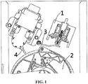
- FIG. 1 a governor assembly of an elevator system is shown.
- the governor assembly includes a sheave 2 having a centrifugal mechanism, a governor switch 4, and a remote triggering apparatus.
- the remote triggering apparatus includes an actuator 1 and a contact mechanism 3.
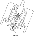
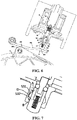
- FIG. 2 shows an enlarged diagram of the actuator 1, including: a mandrel 10, the mandrel 10 having a proximal end 101 and a distal end 102, the proximal end 101 of the mandrel 10 being driven such that the mandrel 10 moves from a contraction position as shown in FIG. 2 to an actuation position as shown in FIG. 5 .
- the actuator 1 further includes a mandrel sleeve 21, the mandrel sleeve 21 being sleeved on the distal end 102 of the mandrel 10; and a shell 50, the shell 50 defining a channel in which the mandrel sleeve 21 moves.
- the actuator further includes at least one sliding member 31, and in a process that the mandrel 10 moves from the contraction position toward the actuation position, at least one sliding member 31 is located at a first radial position where the mandrel 10 is joined to the mandrel sleeve 21, such that the mandrel sleeve 21 can move along the channel together with the mandrel 10. Moreover, at the actuation position, at least one sliding member 31 moves outward radially to a second radial position where the mandrel sleeve 21 is joined to the shell 50, thus locking the mandrel sleeve.
- the first radial position and the second radial position use a center line of the mandrel 10 as a reference.
- the term “at least one sliding member 31" includes one sliding member and multiple sliding blocks.
- the terms “first radial position” and “second radial position” are intended to represent a respective first radial position and a respective second radial position corresponding to each sliding block.
- the mandrel 10 can include a mandrel stick 16 at the proximal end and a mandrel rod 161 at the distal end.
- the mandrel stick 16 has a threaded hole
- a proximal end of the mandrel rod 161 has a bolt
- the mandrel rod 161 is threaded to the mandrel stick 16.
- the mandrel rod 161 can also be connected to the mandrel stick 16 in another manner.
- the mandrel stick 16 can be made of a magnetic material.
- a coil 8 is arranged at the periphery of the mandrel stick 16, and the mandrel stick 16 is driven by a magnetic field generated after the coil 8 is powered on, so as to drive the mandrel rod 161 to move toward the actuation position together.
- the mandrel stick 16 and the mandrel rod 161 are separated, such that the mandrel rod 161 is allowed to be made of a material different from that of the mandrel stick 16, thus being conducive to complex shaping and machining of the mandrel stick 16 and the mandrel rod 161.
- the mandrel stick 16 and the mandrel rod 161 can also be formed integrally.
- the mandrel includes at least one slope 12.
- the slope 12 acts on at least one sliding member 31 and applies a radially outward component force to the at least one sliding member 31, and the radially outward component force urges the at least one sliding member 31 to move from the first radial position to the second radial position.
- the mandrel 10, e.g., the mandrel rod 161 thereof can include a mandrel body 11, a mandrel contraction part 13, and a slope 12 located between the mandrel body 11 and the mandrel contraction part 13.
- the slope 12 can have a linear profile, an arc-shaped profile, or another suitable profile.
- the radially outward force can also be applied by means of another structure, such as a pre-pressed spring and a magnetic force-based attraction or repulsion mechanism, so as to urge the at least one sliding member 31 to move outward radially.
- the at least one sliding member 31 is spherical, thereby facilitating the at least one sliding member to move by means of rolling.
- the at least one sliding member 31 can also have another suitable shape, such as a cylindrical shape and an ellipsoidal shape. It is difficult to view from the longitudinal cross-sectional view as shown, but actually, in the shown embodiment, the at least one sliding member actually includes a first sliding member 31 and a second sliding member 32 that are disposed oppositely and arranged on the periphery of the mandrel symmetrically.
- the at least one sliding member can include more sliding members that are distributed uniformly along the mandrel.
- these sliding members are all spherical, cylindrical, or ellipsoidal, thereby facilitating these sliding members to move by means of rolling.
- the sliding members that are disposed oppositely or distributed along the periphery can balance the force received by the mandrel.
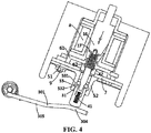
- FIG. 3 further shows a contact plate mechanism 3. More specifically, the contact plate mechanism 3 includes a contact plate 301 enabled by an actuator 1 to move from an idle position to an operating position. The actuator 1 acts on an action point 304 at the back of the contact plate 301, and the contact plate 301 is rotatably fixed at one end through a pin 303 and a contact plate reset spring 302. In some embodiments, the contact plate 301 can have a bent part and defines a smooth contact surface.
- a front end of the mandrel 10 can have a groove 18.
- a side of the groove 18 close to the distal end defines a slope surface 12, and the groove 18 is convenient for defining a position of at least one sliding member.
- the mandrel e.g., the mandrel rod 161
- the mandrel rod 161 further includes a cap 14 sleeved on the tail end of the mandrel contraction part 13.
- the slope surface 12 of the mandrel, the mandrel contraction part 13, and the mandrel cap 14 jointly define the groove 18 on the mandrel.
- the groove 18 of the mandrel is an annular groove surrounding the mandrel contraction part.
- the mandrel may not have a contraction part.
- the groove 18 including a proximal end slope surface 12 can be directly disposed on a side wall of the cylindrical mandrel.
- the groove 18 is unnecessarily annular, and can have another suitable shape, e.g., one or more semi-spherical grooves corresponding to the at least one sliding member.
- the mandrel sleeve 21 is sleeved on the distal end of the mandrel, and at least one opening 22 is provided on the side wall of the mandrel sleeve 21.
- the side wall of the mandrel sleeve 21 has (an) opening(s) 22 of which the position(s) and number(s) correspond to those of the at least one sliding member.
- the at least one sliding member 31 is located at the first radial position between the contraction position shown in FIG. 3 and the actuation position shown in FIG. 5 .
- the first radial position can be located in or between the groove 18 of the mandrel and the at least one opening 22 of the mandrel sleeve. That is, a part of the at least one sliding member 31 is located in the groove 18 of the mandrel, and the other part of the at least one sliding member 31 is located in the at least one opening 22 of the mandrel sleeve, such that the mandrel sleeve 21 is joined or coupled to the mandrel 10, so as to move toward the actuation position jointly along the channel, and push the contact plate 301 ( FIG. 4 ) of the contact mechanism 3.
- the contact plate 3 can be provided with a bend.
- the shell 50 constitutes an actuator front cover.
- the actuator front cover can, for example, be connected to an outer side of an end cover 7 of the actuator through a bolt 9.
- the actuator front cover includes a flat part 51 and a cylindrical part 52 protruded from the flat part.
- An inner side of the cylindrical part 52 defines at least a part of the channel.
- an inner side of the channel of the shell 50 has a recessed part 53.
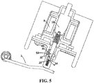
- the recessed part 53 is located at a radial outer side of the at least one sliding member 31 at the actuation position. As shown in FIG. 4 and FIG.
- the at least one sliding member 31 is pushed out by the mandrel 10, e.g., the slope surface 12 of the mandrel and moves to the second radial position.
- the second radial position can be in or between the recessed part 53 of the shell and the opening 22 of the mandrel sleeve 21. That is, a part of the at least one sliding member 31 is located in the recessed part 53, and the other part is located in the opening 22.
- the slope surface 12 of the mandrel 10 acts on the at least one sliding member 31 and applies an action force F to the at least one sliding member.
- the action force F includes a radially outward component force R.
- the at least one sliding member 31 cannot move outward radially due to the side wall of the channel.
- the at least one sliding member 31 can be pushed outward radially and moves to the second radial position.
- the mandrel sleeve 21 defines a bottom 23.
- a gap D still exists between the tail end of the mandrel, e.g., the cap 14 of the mandrel, and the bottom 23 of the mandrel sleeve 21.
- the mandrel 10 is decoupled from the mandrel sleeve 21, and the mandrel 10 is driven to be able to further move forward with respect to the mandrel sleeve 21 in the mandrel sleeve, until the tail end of the mandrel, e.g., the cap 14 of the mandrel, abuts against the bottom 23 of the mandrel sleeve 21.
- the side wall 111 of the mandrel limits the at least one sliding member 53 to the second radial position.
- the contact plate of the contact mechanism 3 acts on a connecting rod connection point 201 of the centrifugal mechanism of the sheave 2 at an action point 305, so as to trigger a governor.
- the connecting rod connection point 201 will bring about a large impact.
- the connecting rod connection point 201 will have a larger rotating speed and larger rotational energy, and the impact is transmitted to the actuator 1 through the contact 301.
- the impact force will be directly transmitted to the mandrel of the actual, such that the mandrel is contracted, thus damaging the actuator.
- the governor is difficult to be triggered. This puts forward more strict requirements for the electromagnetic driving force capability of the actuator, and increases costs of the actuator.
- the mandrel sleeve is joined to the shell, and the impact force applied to the mandrel sleeve is transmitted to the shell without damaging the mandrel. Moreover, it is unnecessary for the mandrel to resist the impact force, and has greatly lowered the requirements for the electromagnetic driving force of the mandrel.
- a first reset spring 41 is disposed between the mandrel and the mandrel sleeve 21.
- the rear end of the mandrel e.g., the mandrel rod 161
- the actuator has an inner cover 61.
- a second reset spring 42 is disposed between the boss 17 and the actuator inner cover 61, e.g., partially accommodated in a notch 62 of the actuator inner cover 61. Under the action of the contact plate reset spring 302, the first reset spring 41, and the second reset spring 42, the actuator can be reset as long as the driving force is removed.
- the actuator contracts to the position shown in FIG. 5 under the action of the first reset spring 41 and the second reset spring 42.
- a push-back force of the contact plate 301 is also applied to the mandrel sleeve 21 under the action of the contact reset spring 302.
- the push-back force is applied to the mandrel sleeve, and therefore, the opening 22 of the mandrel sleeve generates an inward push force Y to the at least one sliding member 31, and the recessed part 53 of the shell generates a counter force f to at least one sliding member 31 that abuts against the recessed part 53, the counter force f having a radially inward component force r.
- the radially inward component force r pushes the at least one sliding member 31 back to the first radial position.
- the whole actuator restores to the contraction position shown in FIG. 1 under the action of the contact plate 301, the first reset spring 41, and the second reset spring 42.
- the recessed part of the inner wall of the channel of the shell can be spherical.
- the recessed part 53 has a first portion 531 close to the proximal end and a second portion 532 close to the distal end.
- the first portion 531 of the recessed part can have a slope angle a less than 45 degrees, or the first portion 531 of the recessed part has a slope angle a less than a slope angle b of the second portion 532 of the recessed part.
- the slope angles a and b are respectively included angles between connection lines, of tops A, B of the two portions of the recessed part and a bottom D, and a reference surface.
- the first portion 531 and the second portion 532 of the recessed part 53 can extend linearly or in an arc shape.
- a remote triggering apparatus and a governor and an elevator having the same are provided.
- the remote triggering apparatus can include the actuator described according to the embodiments.
- the remote triggering apparatus further includes: a contact plate enabled to move from an idle position to an operating position, the actuator acting on the back of the contact plate, and the contact plate being rotatably fixed at one end through a pin and a contact plate reset spring.
- a governor is provided.
- the pin 303 defines a rotation center of the contact plate 301, and an acting force at an action point 304 between the actuator 1 and the contact plate 301 has an arm of force longer than that of an acting force at an action point 305 between the contact plate 301 and the centrifugal mechanism. Therefore, the impact applied to the actuator can be further reduced.
Landscapes
- Physics & Mathematics (AREA)
- Electromagnetism (AREA)
- Engineering & Computer Science (AREA)
- Power Engineering (AREA)
- Mechanical Engineering (AREA)
- Reciprocating, Oscillating Or Vibrating Motors (AREA)
- Electromagnets (AREA)
- Types And Forms Of Lifts (AREA)
Applications Claiming Priority (1)
| Application Number | Priority Date | Filing Date | Title |
|---|---|---|---|
| CN201711021610.XA CN109720957B (zh) | 2017-10-27 | 2017-10-27 | 促动器,远程触发装置,限速器以及电梯 |
Publications (2)
| Publication Number | Publication Date |
|---|---|
| EP3480831A1 true EP3480831A1 (fr) | 2019-05-08 |
| EP3480831B1 EP3480831B1 (fr) | 2020-12-30 |
Family
ID=64277594
Family Applications (1)
| Application Number | Title | Priority Date | Filing Date |
|---|---|---|---|
| EP18205706.7A Active EP3480831B1 (fr) | 2017-10-27 | 2018-11-12 | Actionneur, dispositif de déclenchement à distance et ensemble de régulateur |
Country Status (3)
| Country | Link |
|---|---|
| US (1) | US11524871B2 (fr) |
| EP (1) | EP3480831B1 (fr) |
| CN (1) | CN109720957B (fr) |
Cited By (2)
| Publication number | Priority date | Publication date | Assignee | Title |
|---|---|---|---|---|
| US11414298B2 (en) * | 2017-10-30 | 2022-08-16 | Otis Elevator Company | Governor assembly and elevator system |
| EP4279781A1 (fr) * | 2022-05-18 | 2023-11-22 | Goodrich Corporation | Régulateur de pression actionné par solénoïde pour système de gonflage |
Families Citing this family (3)
| Publication number | Priority date | Publication date | Assignee | Title |
|---|---|---|---|---|
| CN110963387B (zh) * | 2018-09-29 | 2022-06-10 | 奥的斯电梯公司 | 超速保护开关、限速器组件以及电梯系统 |
| CN111268532B (zh) * | 2018-12-04 | 2022-08-30 | 奥的斯电梯公司 | 超速保护开关、限速器组件以及电梯系统 |
| EP3758028B1 (fr) * | 2019-06-24 | 2023-02-15 | Otis Elevator Company | Actionneur |
Citations (3)
| Publication number | Priority date | Publication date | Assignee | Title |
|---|---|---|---|---|
| DE102005056435A1 (de) * | 2005-11-26 | 2007-06-06 | Harting Automotive Gmbh & Co. Kg | Sperrvorrichtung für ein Hub-Magnetsystem |
| EP2380840A1 (fr) * | 2009-01-20 | 2011-10-26 | Mitsubishi Electric Corporation | Dispositif de sécurité pour ascenseur |
| US20130098711A1 (en) | 2010-05-18 | 2013-04-25 | Otis Elevator Company | Integrated elevator safety system |
Family Cites Families (32)
| Publication number | Priority date | Publication date | Assignee | Title |
|---|---|---|---|---|
| US4614097A (en) * | 1983-08-03 | 1986-09-30 | Signorelli John A | Internal locking mechanism for barrel type locks |
| US4623860A (en) * | 1985-06-24 | 1986-11-18 | Synchro-Start Products, Inc. | Latching solenoid mechanism |
| DE8601378U1 (de) | 1986-01-21 | 1987-07-23 | Bongers & Deimann, 4000 Düsseldorf | Vorrichtung zum Begrenzen der Abwärtsbewegung eines Aufzuges |
| US4771255A (en) * | 1987-01-02 | 1988-09-13 | Regdon Solenoid, Inc. | Solenoid with a mechanical locking linkage |
| US4923055A (en) | 1989-01-24 | 1990-05-08 | Delaware Capital Formation, Inc. | Safety mechanism for preventing unintended motion in traction elevators |
| US4951552A (en) * | 1989-11-27 | 1990-08-28 | Fox Anton F | Locking cylinder |
| US5183978A (en) | 1991-04-03 | 1993-02-02 | Otis Elevator Company | Elevator governor rope block actuation in low speed emergency situations |
| US5321216A (en) | 1991-04-09 | 1994-06-14 | Otis Elevator Company | Restraining elevator car motion while the doors are open |
| US5381295A (en) * | 1991-12-12 | 1995-01-10 | Datamax Electronics, Inc. | Resetable battery drain limitation circuit with improved latching relay |
| FI95021C (fi) | 1993-06-08 | 1995-12-11 | Kone Oy | Menetelmä ja laitteisto hissin tarrauslaitteen laukaisemiseksi |
| WO2005092767A1 (fr) | 2004-03-29 | 2005-10-06 | Mitsubishi Denki Kabushiki Kaisha | Méthode pour contrôler le fonctionnement d’un actionneur et dispositif d’inspection de fonctionnement d’actionneur |
| FI120303B (fi) * | 2005-06-23 | 2009-09-15 | Kone Corp | Menetelmä ja laitteisto hissin tarrauslaitteen laukaisemiseksi |
| EP1808397A1 (fr) | 2006-01-11 | 2007-07-18 | BODE Components GmbH | Elément d'arrêt pour dispositif de limitation |
| KR100709506B1 (ko) | 2006-07-26 | 2007-04-20 | (주)광덕산업 | 자동복귀 및 수동트립형 조속기 |
| WO2009130366A1 (fr) | 2008-04-23 | 2009-10-29 | Kone Corporation | Régulateur de survitesse d'un ascenseur, et ascenseur |
| KR101334712B1 (ko) | 2009-03-16 | 2013-11-29 | 오티스 엘리베이터 컴파니 | 과가속 및 과속 검출 및 처리 시스템 |
| FI122262B (fi) | 2009-10-21 | 2011-11-15 | Kone Corp | Hissin liikkeenrajoitin ja hissi |
| JP5609268B2 (ja) * | 2010-05-27 | 2014-10-22 | 三菱電機株式会社 | 巻胴式エレベータの戸開走行防止システム |
| GB2484110A (en) * | 2010-09-30 | 2012-04-04 | Magnet Schultz Ltd | A deadlocking bolt mechanism |
| US9431162B2 (en) * | 2014-02-21 | 2016-08-30 | Magnet-Schultz Of America, Inc. | Coupling with solenoid and spring release mechanism |
| CN104355197B (zh) * | 2014-10-15 | 2016-07-06 | 苏州莱茵电梯股份有限公司 | 无安全绳的电梯限速器 |
| CN105679608B (zh) | 2014-11-17 | 2020-03-13 | 索恩格汽车部件德国有限公司 | 电磁开关及车辆起动机 |
| CN106315334A (zh) * | 2015-06-30 | 2017-01-11 | 天津市国泰电梯部件有限公司 | 一种被安装在电梯轿厢上的电梯限速装置 |
| CN204873326U (zh) * | 2015-08-25 | 2015-12-16 | 宁波奥德普电梯部件有限公司 | 一种电梯限速器 |
| CN107021395B (zh) | 2016-01-04 | 2020-11-10 | 奥的斯电梯公司 | 具有自动复位的电梯超速调节器 |
| CN105752790B (zh) * | 2016-03-24 | 2018-10-12 | 廊坊市久联机械有限公司 | 一种电梯限速器 |
| CN105923499A (zh) * | 2016-06-29 | 2016-09-07 | 西继迅达(许昌)电梯有限公司 | 新型具有速度监控的自动复位单向防溜车限速器 |
| CN206126541U (zh) * | 2016-06-29 | 2017-04-26 | 西继迅达(许昌)电梯有限公司 | 一种新型单向自复位限速器 |
| CN206051201U (zh) * | 2016-08-29 | 2017-03-29 | 杭州沪宁电梯部件股份有限公司 | 一种稳态低速限速器 |
| CN206266033U (zh) | 2016-10-20 | 2017-06-20 | 奥的斯电梯公司 | 远程触发装置,限速器组件以及电梯 |
| US11377873B2 (en) * | 2019-03-12 | 2022-07-05 | Schlage Lock Company Llc | Electric latch mechanism |
| US11710592B2 (en) * | 2019-11-17 | 2023-07-25 | Littelfuse, Inc. | Bi-stable mechanical latch including positioning spheres |
-
2017
- 2017-10-27 CN CN201711021610.XA patent/CN109720957B/zh active Active
-
2018
- 2018-10-24 US US16/169,595 patent/US11524871B2/en active Active
- 2018-11-12 EP EP18205706.7A patent/EP3480831B1/fr active Active
Patent Citations (3)
| Publication number | Priority date | Publication date | Assignee | Title |
|---|---|---|---|---|
| DE102005056435A1 (de) * | 2005-11-26 | 2007-06-06 | Harting Automotive Gmbh & Co. Kg | Sperrvorrichtung für ein Hub-Magnetsystem |
| EP2380840A1 (fr) * | 2009-01-20 | 2011-10-26 | Mitsubishi Electric Corporation | Dispositif de sécurité pour ascenseur |
| US20130098711A1 (en) | 2010-05-18 | 2013-04-25 | Otis Elevator Company | Integrated elevator safety system |
Cited By (2)
| Publication number | Priority date | Publication date | Assignee | Title |
|---|---|---|---|---|
| US11414298B2 (en) * | 2017-10-30 | 2022-08-16 | Otis Elevator Company | Governor assembly and elevator system |
| EP4279781A1 (fr) * | 2022-05-18 | 2023-11-22 | Goodrich Corporation | Régulateur de pression actionné par solénoïde pour système de gonflage |
Also Published As
| Publication number | Publication date |
|---|---|
| CN109720957B (zh) | 2021-11-02 |
| CN109720957A (zh) | 2019-05-07 |
| EP3480831B1 (fr) | 2020-12-30 |
| US11524871B2 (en) | 2022-12-13 |
| US20190127179A1 (en) | 2019-05-02 |
Similar Documents
| Publication | Publication Date | Title |
|---|---|---|
| US11524871B2 (en) | Actuator, remote triggering device, governor assembly and elevator | |
| US10914103B2 (en) | Electronic handle for a vehicle door | |
| JP7139425B2 (ja) | 自動車のドアリーフの部分的開扉システム | |
| US10767402B2 (en) | Door check and method for blocking a door check | |
| JP6078311B2 (ja) | 自動的にロックするリニアアクチュエータ | |
| CN109509648B (zh) | 用于切换装置的减速机构和切换装置 | |
| CN109789995B (zh) | 用于操纵电梯设备的制动器的机电式操纵器 | |
| CN206266033U (zh) | 远程触发装置,限速器组件以及电梯 | |
| US12134459B2 (en) | Air vehicle | |
| EP3476788B1 (fr) | Ensemble régulateur et système d'ascenseur | |
| EP3505481B1 (fr) | Dispositif de déclenchement à distance, ensemble de régulateur et ascenseur | |
| CN114843124A (zh) | 开关电动操作分合闸机构和接地开关 | |
| WO2016078625A1 (fr) | Mécanisme de contact mobile de commutateur haute tension et commutateur haute tension l'utilisant | |
| CN203146738U (zh) | 滚珠丝杠的锁定装置 | |
| EP1811108A1 (fr) | Mécanisme de verrouillage | |
| CN113983088B (zh) | 制动器及手动制动装置、被动使能万向轮、手术机器人 | |
| JP7546865B2 (ja) | 航空機の降着装置用電動アクチュエータ | |
| CN219174088U (zh) | 一种绞盘离合结构及绞盘 | |
| CN222513439U (zh) | 一种投放器自动开门机构 | |
| CN223785871U (zh) | 设有限位机构的低损耗直行程执行器 | |
| EP4270439A1 (fr) | Interrupteur de refermeture capable d'ouvrir et de fermer de manière stable | |
| CN109404446B (zh) | 驻车执行器和具有其的车辆 | |
| JP2002130415A (ja) | 作動装置のボールねじストッパ構造 | |
| EP4201866A1 (fr) | Treuil mécanique avec un commutateur mécanique pour terminer l'enroulement d'un câble sur le tambour du treuil | |
| CN118888355A (zh) | 一种操动机构 |
Legal Events
| Date | Code | Title | Description |
|---|---|---|---|
| PUAI | Public reference made under article 153(3) epc to a published international application that has entered the european phase |
Free format text: ORIGINAL CODE: 0009012 |
|
| STAA | Information on the status of an ep patent application or granted ep patent |
Free format text: STATUS: THE APPLICATION HAS BEEN PUBLISHED |
|
| AK | Designated contracting states |
Kind code of ref document: A1 Designated state(s): AL AT BE BG CH CY CZ DE DK EE ES FI FR GB GR HR HU IE IS IT LI LT LU LV MC MK MT NL NO PL PT RO RS SE SI SK SM TR |
|
| AX | Request for extension of the european patent |
Extension state: BA ME |
|
| RIN1 | Information on inventor provided before grant (corrected) |
Inventor name: SHI, ZHENGBAO |
|
| STAA | Information on the status of an ep patent application or granted ep patent |
Free format text: STATUS: REQUEST FOR EXAMINATION WAS MADE |
|
| 17P | Request for examination filed |
Effective date: 20191028 |
|
| RBV | Designated contracting states (corrected) |
Designated state(s): AL AT BE BG CH CY CZ DE DK EE ES FI FR GB GR HR HU IE IS IT LI LT LU LV MC MK MT NL NO PL PT RO RS SE SI SK SM TR |
|
| GRAP | Despatch of communication of intention to grant a patent |
Free format text: ORIGINAL CODE: EPIDOSNIGR1 |
|
| STAA | Information on the status of an ep patent application or granted ep patent |
Free format text: STATUS: GRANT OF PATENT IS INTENDED |
|
| INTG | Intention to grant announced |
Effective date: 20200706 |
|
| RIN1 | Information on inventor provided before grant (corrected) |
Inventor name: SHI, ZHENGBAO |
|
| GRAS | Grant fee paid |
Free format text: ORIGINAL CODE: EPIDOSNIGR3 |
|
| GRAA | (expected) grant |
Free format text: ORIGINAL CODE: 0009210 |
|
| STAA | Information on the status of an ep patent application or granted ep patent |
Free format text: STATUS: THE PATENT HAS BEEN GRANTED |
|
| AK | Designated contracting states |
Kind code of ref document: B1 Designated state(s): AL AT BE BG CH CY CZ DE DK EE ES FI FR GB GR HR HU IE IS IT LI LT LU LV MC MK MT NL NO PL PT RO RS SE SI SK SM TR |
|
| REG | Reference to a national code |
Ref country code: GB Ref legal event code: FG4D |
|
| REG | Reference to a national code |
Ref country code: DE Ref legal event code: R096 Ref document number: 602018011297 Country of ref document: DE |
|
| REG | Reference to a national code |
Ref country code: AT Ref legal event code: REF Ref document number: 1350751 Country of ref document: AT Kind code of ref document: T Effective date: 20210115 |
|
| REG | Reference to a national code |
Ref country code: IE Ref legal event code: FG4D |
|
| PG25 | Lapsed in a contracting state [announced via postgrant information from national office to epo] |
Ref country code: RS Free format text: LAPSE BECAUSE OF FAILURE TO SUBMIT A TRANSLATION OF THE DESCRIPTION OR TO PAY THE FEE WITHIN THE PRESCRIBED TIME-LIMIT Effective date: 20201230 Ref country code: FI Free format text: LAPSE BECAUSE OF FAILURE TO SUBMIT A TRANSLATION OF THE DESCRIPTION OR TO PAY THE FEE WITHIN THE PRESCRIBED TIME-LIMIT Effective date: 20201230 Ref country code: GR Free format text: LAPSE BECAUSE OF FAILURE TO SUBMIT A TRANSLATION OF THE DESCRIPTION OR TO PAY THE FEE WITHIN THE PRESCRIBED TIME-LIMIT Effective date: 20210331 Ref country code: NO Free format text: LAPSE BECAUSE OF FAILURE TO SUBMIT A TRANSLATION OF THE DESCRIPTION OR TO PAY THE FEE WITHIN THE PRESCRIBED TIME-LIMIT Effective date: 20210330 |
|
| REG | Reference to a national code |
Ref country code: AT Ref legal event code: MK05 Ref document number: 1350751 Country of ref document: AT Kind code of ref document: T Effective date: 20201230 |
|
| PG25 | Lapsed in a contracting state [announced via postgrant information from national office to epo] |
Ref country code: BG Free format text: LAPSE BECAUSE OF FAILURE TO SUBMIT A TRANSLATION OF THE DESCRIPTION OR TO PAY THE FEE WITHIN THE PRESCRIBED TIME-LIMIT Effective date: 20210330 Ref country code: SE Free format text: LAPSE BECAUSE OF FAILURE TO SUBMIT A TRANSLATION OF THE DESCRIPTION OR TO PAY THE FEE WITHIN THE PRESCRIBED TIME-LIMIT Effective date: 20201230 Ref country code: LV Free format text: LAPSE BECAUSE OF FAILURE TO SUBMIT A TRANSLATION OF THE DESCRIPTION OR TO PAY THE FEE WITHIN THE PRESCRIBED TIME-LIMIT Effective date: 20201230 |
|
| REG | Reference to a national code |
Ref country code: NL Ref legal event code: MP Effective date: 20201230 |
|
| PG25 | Lapsed in a contracting state [announced via postgrant information from national office to epo] |
Ref country code: HR Free format text: LAPSE BECAUSE OF FAILURE TO SUBMIT A TRANSLATION OF THE DESCRIPTION OR TO PAY THE FEE WITHIN THE PRESCRIBED TIME-LIMIT Effective date: 20201230 |
|
| REG | Reference to a national code |
Ref country code: LT Ref legal event code: MG9D |
|
| PG25 | Lapsed in a contracting state [announced via postgrant information from national office to epo] |
Ref country code: CZ Free format text: LAPSE BECAUSE OF FAILURE TO SUBMIT A TRANSLATION OF THE DESCRIPTION OR TO PAY THE FEE WITHIN THE PRESCRIBED TIME-LIMIT Effective date: 20201230 Ref country code: EE Free format text: LAPSE BECAUSE OF FAILURE TO SUBMIT A TRANSLATION OF THE DESCRIPTION OR TO PAY THE FEE WITHIN THE PRESCRIBED TIME-LIMIT Effective date: 20201230 Ref country code: SK Free format text: LAPSE BECAUSE OF FAILURE TO SUBMIT A TRANSLATION OF THE DESCRIPTION OR TO PAY THE FEE WITHIN THE PRESCRIBED TIME-LIMIT Effective date: 20201230 Ref country code: PT Free format text: LAPSE BECAUSE OF FAILURE TO SUBMIT A TRANSLATION OF THE DESCRIPTION OR TO PAY THE FEE WITHIN THE PRESCRIBED TIME-LIMIT Effective date: 20210430 Ref country code: RO Free format text: LAPSE BECAUSE OF FAILURE TO SUBMIT A TRANSLATION OF THE DESCRIPTION OR TO PAY THE FEE WITHIN THE PRESCRIBED TIME-LIMIT Effective date: 20201230 Ref country code: LT Free format text: LAPSE BECAUSE OF FAILURE TO SUBMIT A TRANSLATION OF THE DESCRIPTION OR TO PAY THE FEE WITHIN THE PRESCRIBED TIME-LIMIT Effective date: 20201230 |
|
| PG25 | Lapsed in a contracting state [announced via postgrant information from national office to epo] |
Ref country code: AT Free format text: LAPSE BECAUSE OF FAILURE TO SUBMIT A TRANSLATION OF THE DESCRIPTION OR TO PAY THE FEE WITHIN THE PRESCRIBED TIME-LIMIT Effective date: 20201230 Ref country code: PL Free format text: LAPSE BECAUSE OF FAILURE TO SUBMIT A TRANSLATION OF THE DESCRIPTION OR TO PAY THE FEE WITHIN THE PRESCRIBED TIME-LIMIT Effective date: 20201230 |
|
| PG25 | Lapsed in a contracting state [announced via postgrant information from national office to epo] |
Ref country code: IS Free format text: LAPSE BECAUSE OF FAILURE TO SUBMIT A TRANSLATION OF THE DESCRIPTION OR TO PAY THE FEE WITHIN THE PRESCRIBED TIME-LIMIT Effective date: 20210430 |
|
| REG | Reference to a national code |
Ref country code: DE Ref legal event code: R097 Ref document number: 602018011297 Country of ref document: DE |
|
| PG25 | Lapsed in a contracting state [announced via postgrant information from national office to epo] |
Ref country code: AL Free format text: LAPSE BECAUSE OF FAILURE TO SUBMIT A TRANSLATION OF THE DESCRIPTION OR TO PAY THE FEE WITHIN THE PRESCRIBED TIME-LIMIT Effective date: 20201230 Ref country code: IT Free format text: LAPSE BECAUSE OF FAILURE TO SUBMIT A TRANSLATION OF THE DESCRIPTION OR TO PAY THE FEE WITHIN THE PRESCRIBED TIME-LIMIT Effective date: 20201230 |
|
| PLBE | No opposition filed within time limit |
Free format text: ORIGINAL CODE: 0009261 |
|
| STAA | Information on the status of an ep patent application or granted ep patent |
Free format text: STATUS: NO OPPOSITION FILED WITHIN TIME LIMIT |
|
| PG25 | Lapsed in a contracting state [announced via postgrant information from national office to epo] |
Ref country code: DK Free format text: LAPSE BECAUSE OF FAILURE TO SUBMIT A TRANSLATION OF THE DESCRIPTION OR TO PAY THE FEE WITHIN THE PRESCRIBED TIME-LIMIT Effective date: 20201230 |
|
| 26N | No opposition filed |
Effective date: 20211001 |
|
| PG25 | Lapsed in a contracting state [announced via postgrant information from national office to epo] |
Ref country code: ES Free format text: LAPSE BECAUSE OF FAILURE TO SUBMIT A TRANSLATION OF THE DESCRIPTION OR TO PAY THE FEE WITHIN THE PRESCRIBED TIME-LIMIT Effective date: 20201230 |
|
| PG25 | Lapsed in a contracting state [announced via postgrant information from national office to epo] |
Ref country code: SI Free format text: LAPSE BECAUSE OF FAILURE TO SUBMIT A TRANSLATION OF THE DESCRIPTION OR TO PAY THE FEE WITHIN THE PRESCRIBED TIME-LIMIT Effective date: 20201230 |
|
| PG25 | Lapsed in a contracting state [announced via postgrant information from national office to epo] |
Ref country code: IS Free format text: LAPSE BECAUSE OF FAILURE TO SUBMIT A TRANSLATION OF THE DESCRIPTION OR TO PAY THE FEE WITHIN THE PRESCRIBED TIME-LIMIT Effective date: 20210430 |
|
| PG25 | Lapsed in a contracting state [announced via postgrant information from national office to epo] |
Ref country code: MC Free format text: LAPSE BECAUSE OF FAILURE TO SUBMIT A TRANSLATION OF THE DESCRIPTION OR TO PAY THE FEE WITHIN THE PRESCRIBED TIME-LIMIT Effective date: 20201230 |
|
| REG | Reference to a national code |
Ref country code: CH Ref legal event code: PL |
|
| PG25 | Lapsed in a contracting state [announced via postgrant information from national office to epo] |
Ref country code: LU Free format text: LAPSE BECAUSE OF NON-PAYMENT OF DUE FEES Effective date: 20211112 Ref country code: BE Free format text: LAPSE BECAUSE OF NON-PAYMENT OF DUE FEES Effective date: 20211130 |
|
| REG | Reference to a national code |
Ref country code: BE Ref legal event code: MM Effective date: 20211130 |
|
| PG25 | Lapsed in a contracting state [announced via postgrant information from national office to epo] |
Ref country code: IE Free format text: LAPSE BECAUSE OF NON-PAYMENT OF DUE FEES Effective date: 20211112 |
|
| PG25 | Lapsed in a contracting state [announced via postgrant information from national office to epo] |
Ref country code: NL Free format text: LAPSE BECAUSE OF NON-PAYMENT OF DUE FEES Effective date: 20201230 Ref country code: CY Free format text: LAPSE BECAUSE OF FAILURE TO SUBMIT A TRANSLATION OF THE DESCRIPTION OR TO PAY THE FEE WITHIN THE PRESCRIBED TIME-LIMIT Effective date: 20201230 |
|
| GBPC | Gb: european patent ceased through non-payment of renewal fee |
Effective date: 20221112 |
|
| PG25 | Lapsed in a contracting state [announced via postgrant information from national office to epo] |
Ref country code: SM Free format text: LAPSE BECAUSE OF FAILURE TO SUBMIT A TRANSLATION OF THE DESCRIPTION OR TO PAY THE FEE WITHIN THE PRESCRIBED TIME-LIMIT Effective date: 20201230 Ref country code: LI Free format text: LAPSE BECAUSE OF NON-PAYMENT OF DUE FEES Effective date: 20220701 Ref country code: HU Free format text: LAPSE BECAUSE OF FAILURE TO SUBMIT A TRANSLATION OF THE DESCRIPTION OR TO PAY THE FEE WITHIN THE PRESCRIBED TIME-LIMIT; INVALID AB INITIO Effective date: 20181112 Ref country code: CH Free format text: LAPSE BECAUSE OF NON-PAYMENT OF DUE FEES Effective date: 20220701 |
|
| PG25 | Lapsed in a contracting state [announced via postgrant information from national office to epo] |
Ref country code: GB Free format text: LAPSE BECAUSE OF NON-PAYMENT OF DUE FEES Effective date: 20221112 |
|
| PG25 | Lapsed in a contracting state [announced via postgrant information from national office to epo] |
Ref country code: MK Free format text: LAPSE BECAUSE OF FAILURE TO SUBMIT A TRANSLATION OF THE DESCRIPTION OR TO PAY THE FEE WITHIN THE PRESCRIBED TIME-LIMIT Effective date: 20201230 |
|
| PG25 | Lapsed in a contracting state [announced via postgrant information from national office to epo] |
Ref country code: TR Free format text: LAPSE BECAUSE OF FAILURE TO SUBMIT A TRANSLATION OF THE DESCRIPTION OR TO PAY THE FEE WITHIN THE PRESCRIBED TIME-LIMIT Effective date: 20201230 |
|
| PG25 | Lapsed in a contracting state [announced via postgrant information from national office to epo] |
Ref country code: MT Free format text: LAPSE BECAUSE OF FAILURE TO SUBMIT A TRANSLATION OF THE DESCRIPTION OR TO PAY THE FEE WITHIN THE PRESCRIBED TIME-LIMIT Effective date: 20201230 |
|
| PGFP | Annual fee paid to national office [announced via postgrant information from national office to epo] |
Ref country code: DE Payment date: 20251022 Year of fee payment: 8 |
|
| PGFP | Annual fee paid to national office [announced via postgrant information from national office to epo] |
Ref country code: FR Payment date: 20251023 Year of fee payment: 8 |