EP3482985A1 - Elektrische maschine mit doppelantrieb mit steuerbarem planetengetriebesatz - Google Patents
Elektrische maschine mit doppelantrieb mit steuerbarem planetengetriebesatz Download PDFInfo
- Publication number
- EP3482985A1 EP3482985A1 EP18211765.5A EP18211765A EP3482985A1 EP 3482985 A1 EP3482985 A1 EP 3482985A1 EP 18211765 A EP18211765 A EP 18211765A EP 3482985 A1 EP3482985 A1 EP 3482985A1
- Authority
- EP
- European Patent Office
- Prior art keywords
- rotation shaft
- electric machine
- brake device
- dual
- controllable brake
- Prior art date
- Legal status (The legal status is an assumption and is not a legal conclusion. Google has not performed a legal analysis and makes no representation as to the accuracy of the status listed.)
- Granted
Links
Images


Classifications
-
- B—PERFORMING OPERATIONS; TRANSPORTING
- B60—VEHICLES IN GENERAL
- B60K—ARRANGEMENT OR MOUNTING OF PROPULSION UNITS OR OF TRANSMISSIONS IN VEHICLES; ARRANGEMENT OR MOUNTING OF PLURAL DIVERSE PRIME-MOVERS IN VEHICLES; AUXILIARY DRIVES FOR VEHICLES; INSTRUMENTATION OR DASHBOARDS FOR VEHICLES; ARRANGEMENTS IN CONNECTION WITH COOLING, AIR INTAKE, GAS EXHAUST OR FUEL SUPPLY OF PROPULSION UNITS IN VEHICLES
- B60K6/00—Arrangement or mounting of plural diverse prime-movers for mutual or common propulsion, e.g. hybrid propulsion systems comprising electric motors and internal combustion engines
- B60K6/20—Arrangement or mounting of plural diverse prime-movers for mutual or common propulsion, e.g. hybrid propulsion systems comprising electric motors and internal combustion engines the prime-movers consisting of electric motors and internal combustion engines, e.g. HEVs
- B60K6/22—Arrangement or mounting of plural diverse prime-movers for mutual or common propulsion, e.g. hybrid propulsion systems comprising electric motors and internal combustion engines the prime-movers consisting of electric motors and internal combustion engines, e.g. HEVs characterised by apparatus, components or means specially adapted for HEVs
- B60K6/36—Arrangement or mounting of plural diverse prime-movers for mutual or common propulsion, e.g. hybrid propulsion systems comprising electric motors and internal combustion engines the prime-movers consisting of electric motors and internal combustion engines, e.g. HEVs characterised by apparatus, components or means specially adapted for HEVs characterised by the transmission gearings
- B60K6/365—Arrangement or mounting of plural diverse prime-movers for mutual or common propulsion, e.g. hybrid propulsion systems comprising electric motors and internal combustion engines the prime-movers consisting of electric motors and internal combustion engines, e.g. HEVs characterised by apparatus, components or means specially adapted for HEVs characterised by the transmission gearings with the gears having orbital motion
-
- B—PERFORMING OPERATIONS; TRANSPORTING
- B60—VEHICLES IN GENERAL
- B60K—ARRANGEMENT OR MOUNTING OF PROPULSION UNITS OR OF TRANSMISSIONS IN VEHICLES; ARRANGEMENT OR MOUNTING OF PLURAL DIVERSE PRIME-MOVERS IN VEHICLES; AUXILIARY DRIVES FOR VEHICLES; INSTRUMENTATION OR DASHBOARDS FOR VEHICLES; ARRANGEMENTS IN CONNECTION WITH COOLING, AIR INTAKE, GAS EXHAUST OR FUEL SUPPLY OF PROPULSION UNITS IN VEHICLES
- B60K6/00—Arrangement or mounting of plural diverse prime-movers for mutual or common propulsion, e.g. hybrid propulsion systems comprising electric motors and internal combustion engines
- B60K6/20—Arrangement or mounting of plural diverse prime-movers for mutual or common propulsion, e.g. hybrid propulsion systems comprising electric motors and internal combustion engines the prime-movers consisting of electric motors and internal combustion engines, e.g. HEVs
- B60K6/42—Arrangement or mounting of plural diverse prime-movers for mutual or common propulsion, e.g. hybrid propulsion systems comprising electric motors and internal combustion engines the prime-movers consisting of electric motors and internal combustion engines, e.g. HEVs characterised by the architecture of the hybrid electric vehicle
- B60K6/48—Parallel type
-
- F—MECHANICAL ENGINEERING; LIGHTING; HEATING; WEAPONS; BLASTING
- F16—ENGINEERING ELEMENTS AND UNITS; GENERAL MEASURES FOR PRODUCING AND MAINTAINING EFFECTIVE FUNCTIONING OF MACHINES OR INSTALLATIONS; THERMAL INSULATION IN GENERAL
- F16H—GEARING
- F16H3/00—Toothed gearings for conveying rotary motion with variable gear ratio or for reversing rotary motion
- F16H3/44—Toothed gearings for conveying rotary motion with variable gear ratio or for reversing rotary motion using gears having orbital motion
- F16H3/72—Toothed gearings for conveying rotary motion with variable gear ratio or for reversing rotary motion using gears having orbital motion with a secondary drive, e.g. regulating motor, in order to vary speed continuously
- F16H3/724—Toothed gearings for conveying rotary motion with variable gear ratio or for reversing rotary motion using gears having orbital motion with a secondary drive, e.g. regulating motor, in order to vary speed continuously using externally powered electric machines
-
- B—PERFORMING OPERATIONS; TRANSPORTING
- B60—VEHICLES IN GENERAL
- B60K—ARRANGEMENT OR MOUNTING OF PROPULSION UNITS OR OF TRANSMISSIONS IN VEHICLES; ARRANGEMENT OR MOUNTING OF PLURAL DIVERSE PRIME-MOVERS IN VEHICLES; AUXILIARY DRIVES FOR VEHICLES; INSTRUMENTATION OR DASHBOARDS FOR VEHICLES; ARRANGEMENTS IN CONNECTION WITH COOLING, AIR INTAKE, GAS EXHAUST OR FUEL SUPPLY OF PROPULSION UNITS IN VEHICLES
- B60K6/00—Arrangement or mounting of plural diverse prime-movers for mutual or common propulsion, e.g. hybrid propulsion systems comprising electric motors and internal combustion engines
- B60K6/20—Arrangement or mounting of plural diverse prime-movers for mutual or common propulsion, e.g. hybrid propulsion systems comprising electric motors and internal combustion engines the prime-movers consisting of electric motors and internal combustion engines, e.g. HEVs
- B60K6/22—Arrangement or mounting of plural diverse prime-movers for mutual or common propulsion, e.g. hybrid propulsion systems comprising electric motors and internal combustion engines the prime-movers consisting of electric motors and internal combustion engines, e.g. HEVs characterised by apparatus, components or means specially adapted for HEVs
- B60K6/26—Arrangement or mounting of plural diverse prime-movers for mutual or common propulsion, e.g. hybrid propulsion systems comprising electric motors and internal combustion engines the prime-movers consisting of electric motors and internal combustion engines, e.g. HEVs characterised by apparatus, components or means specially adapted for HEVs characterised by the motors or the generators
- B60K2006/262—Arrangement or mounting of plural diverse prime-movers for mutual or common propulsion, e.g. hybrid propulsion systems comprising electric motors and internal combustion engines the prime-movers consisting of electric motors and internal combustion engines, e.g. HEVs characterised by apparatus, components or means specially adapted for HEVs characterised by the motors or the generators the motor or generator are used as clutch, e.g. between engine and driveshaft
-
- Y—GENERAL TAGGING OF NEW TECHNOLOGICAL DEVELOPMENTS; GENERAL TAGGING OF CROSS-SECTIONAL TECHNOLOGIES SPANNING OVER SEVERAL SECTIONS OF THE IPC; TECHNICAL SUBJECTS COVERED BY FORMER USPC CROSS-REFERENCE ART COLLECTIONS [XRACs] AND DIGESTS
- Y02—TECHNOLOGIES OR APPLICATIONS FOR MITIGATION OR ADAPTATION AGAINST CLIMATE CHANGE
- Y02T—CLIMATE CHANGE MITIGATION TECHNOLOGIES RELATED TO TRANSPORTATION
- Y02T10/00—Road transport of goods or passengers
- Y02T10/60—Other road transportation technologies with climate change mitigation effect
- Y02T10/62—Hybrid vehicles
Definitions
- the present invention relates to a clutch device structured by a dual-drive electric machine being combined with an planetary gear set (DG101) and a controllable brake device, and through controlling the controllable brake device to perform brake locking or releasing, the operations of transmission function of connecting transmission or releasing between a rotation shaft (S101) at an output/input end, a rotation shaft (SI02) at an output/input end and a sleeve type rotation shaft (AS101) at an output/input end of the planetary gear set (DG101) are enabled to be controlled, thereby to control the interactive operations between the dual-drive electric machine (EM100) and the output/input ends.
- a friction type electromagnetic clutch device is often installed between the output/input end of a rotation electric machine and a load; and through electrically charging or breaking the friction type electromagnetic clutch device to perform operations of combining or releasing, the load is enabled to engaged or released with the rotary electric machine.
- One primary disadvantage of the conventional arts is that residual rotary torque is often remained during the releasing, which may cause the kinetic energy loss and the ineffective operation.
- the present invention relates to a clutch device structured by a dual-drive electric machine being combined with an planetary gear set (DG101) and a controllable brake device, and through controlling the controllable brake device to perform brake locking or releasing, the operations of transmission function of connecting transmission or releasing between a rotation shaft (S101) at an output/input end, a rotation shaft (SI02) at an output/input end and a sleeve type rotation shaft (AS101) at an output/input end of the planetary gear set (DG101) are enabled to be controlled, thereby to control the interactive operations between the dual-drive electric machine (EM100) and the output/input ends.
- a drive device comprises: a first rotation shaft (S101); a second rotation shaft (S102); a dual-drive electric machine (EM100); a planetary gear set (DG101) combined with the dual-drive electric machine (EM100), the combination being disposed between the first rotation shaft (S101) and the second rotation shaft (SI02) so that the first rotation shaft (S101) forms a first output/input end and the second rotation shaft (SI02) forms a second output/input end; and a brake device controllable to operate between a brake locked configuration and a brake released configuration whereby operation of the brake has the effect of operating the device as a clutch device.
- more than one brake device is included in the clutch device.
- the brake device or devices may be located in a number of positions within the clutch device.
- the controllable brake device performs brake locking and releasing operations.
- a friction type electromagnetic clutch device is often installed between the output/input end of a rotation electric machine and a load; and through electrically charging or breaking the friction type electromagnetic clutch device to perform operations of combining or releasing, the load is enabled to engaged or released with the rotary electric machine.
- One primary disadvantage of the conventional arts is that residual rotary torque is often remained during the releasing, which may cause the kinetic energy loss and the ineffective operation.
- the present invention provides a dual-drive electric machine having a controllable planetary gear set, in which an inner rotation part of the electric machine (EM101) of the dual-drive electric machine (EM100) being combined with a sun wheel (W101) of an planetary gear set (DG101) and combined with a rotation shaft (S101) shared by the above two is served as an output/input end, a rotation shaft (S102) combined with an outer annular wheel (W102) is served as an output/input end, and a rocker arm (A101) linked by an planetary wheel (W103) of the planetary gear set (DG101) combined with an outer rotation part of electric machine (EM102) and combined with a sleeve type rotation shaft (AS101) is served as an output/input end, so that a part or all of the three output/input ends are respectively connected to an action side of a corresponding controllable brake device, and the other action side of the controllable brake device is connected to a housing (H100); through controlling the controllable
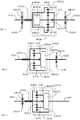
- FIG. 1 is a schematic structural view showing the rotation shaft (S101) shared by the sun wheel (W101) of the planetary gear set (DG101) and the inner rotation part of electric machine (EM101) of the dual-drive electric machine (EM100) being served as an output/input end, the rocker arm (A101) linked by the planetary wheel (W103) being combined with the outer rotation part of electric machine (EM102) and combined with the sleeve type rotation shaft (AS101), the sleeve type rotation shaft (AS101) rotated and sleeved on the rotation shaft (S101) being served as an output/input end and provided for connecting to an action side of the controllable brake device (BK101) while the other action side of the controllable brake device (BK101) being fixed in the housing (H100), the planetary gear set (DG101) also being fixed in the housing (H100), and the outer annul
- FIG 1 it mainly consists of:
- FIG. 2 is a schematic structural view showing the rotation shaft (S101) shared by the sun wheel (W101) of the planetary gear set (DG101) and the inner rotation part of electric machine (EM101) of the dual-drive electric machine (EM100) being served as an output/input end, the rocker arm (A101) linked by the planetary wheel (W103) being combined with the outer rotation part of electric machine (EM102) and combined with the sleeve type rotation shaft (AS101), the sleeve type rotation shaft (AS101) sleeved on the rotation shaft (S101) being served as an output/input end, the outer annular wheel (W102) of the planetary gear set (DG101) being provided for driving the rotation shaft (SI02) to be served as an output/input end, and the rotation shaft (SI02) being connected to an action side of the controllable brake device (BK102) while the other action side of the controllable brake device (BK102) being fixed in the housing (H100), according to one embodiment of
- FIG 2 it mainly consists of:
- FIG. 3 is a schematic structural view showing the rotation shaft (S101) shared by the sun wheel (W101) of the planetary gear set (DG101) and the inner rotation part of electric machine (EM101) of the dual-drive electric machine (EM100) being served as an output/input end and provided for connecting with an action side of the controllable brake device (BK103) while the other action side of the controllable brake device (BK103) being fixed in the housing (H100), the planetary gear set (DG101) also being fixed in the housing (H100), the planetary wheel (W103) of the planetary gear set (DG101) being provided for linking the rocker arm (A101) and combined with the outer rotation part of electric machine (EM102) and the sleeve type rotation shaft (AS101), the sleeve type rotation shaft (AS101) being served as an output/input end, and the outer annular wheel (W102) of the planetary gear set (DG101) being provided for driving the rotation shaft (SI02) to be served as an output/in
- the interactive operations of corresponding function performed by the mentioned dual-drive electric machine (EM100) include receiving the driving control of externally inputted electric energy to operate as the motor function for individually driving the load, or working with the externally inputted rotary kinetic energy for commonly driving the load;
- the interactive operations of corresponding function performed by the mentioned dual-drive electric machine (EM100) include receiving the driving of the externally inputted rotary kinetic energy or the driving of the load inertia kinetic energy for being operated as the power generator function, so as to output the electric energy to drive the external electric load or charge the external electric energy storing device.
- FIG. 4 is a schematic structural view showing the controllable brake device (BK103) being further installed between the rotation shaft (S101) and the housing (H100) as shown in FIG. 2 .
- the rotation shaft (S101) shared by the sun wheel (W101) of the planetary gear set (DG101) and the inner rotation part of electric machine (EM101) of the dual-drive electric machine (EM100) is served as an output/input end and provided for connecting to an action side of the controllable brake device (BK103) while the other action side of the controllable brake device (BK103) is fixed in the housing (H100), the planetary gear set (DG101) is also fixed in the housing (H100), the planetary wheel (W103) of the planetary gear set (DG101) is provided for linking the rocker arm (A101) and combined with the outer rotation part of electric machine (EM102) and combined with the sleeve type rotation shaft (AS101), and the sleeve type rotation shaft (AS101) rotated and sleeved on the rotation shaft (S101) is served as an output/input end, the outer annular wheel (W102) of the planetary gear set (DG101) is provided for driving
- FIG. 5 is a schematic structural view showing the rotation shaft (S101) shared by the sun wheel (W101) of the planetary gear set (DG101) and the inner rotation part of electric machine (EM101) of the dual-drive electric machine (EM100) being served as an output/input end, the outer annular wheel (W102) being combined with the outer rotation part of electric machine (EM102) and combined with the sleeve type rotation shaft (AS101), the sleeve type rotation shaft (AS101) sleeved on the rotation shaft (S101) being served as an output/input end, the rocker arm (A101) linked by the planetary wheel (W103) of the planetary gear set (DG101) being provided for driving the rotation shaft (SI02) to be served as an output/input end, and the rotation shaft (S102) or the rocker arm (A101) being connected to an action side of the controllable brake device (BK102) while the other action side of the controllable brake device (BK102) being fixed in the housing (
- the operations include one or more than one of following functions:
- FIG. 6 is a schematic structural view showing the rotation shaft (S101) shared by the sun wheel (W101) of the planetary gear set (DG101) and the inner rotation part of electric machine (EM101) of the dual-drive electric machine (EM100) being served as an output/input end and provided for connecting to an action side of the controllable brake device (BK103) while the other action side of the controllable brake device (BK103) being fixed in the housing (H100), the planetary gear set (DG101) also being fixed in the housing (H100), the outer annular wheel (W102) of the planetary gear set (DG101) being combined with the outer rotation part of electric machine (EM102) and the sleeve type rotation shaft (AS101), the sleeve type rotation shaft (AS101) being served as an output/input end, and the planetary wheel (W103) of the planetary gear set (DG101) being provided for linking the rocker arm (A101) and driving the rotation shaft (S102) to be served as an output/input end,
- the operations include one or more than one of following functions:
- FIG. 7 is a schematic structural view showing the controllable brake device (BK103) being further installed between the rotation shaft (S101) and the housing (H100) as shown in FIG. 5 .
- the rotation shaft (S101) shared by the sun wheel (W101) of the planetary gear set (DG101) and the inner rotation part of electric machine (EM101) of the dual-drive electric machine (EM100) is served as an output/input end, and is provided for connecting to an action side of the controllable brake device (BK103) while the other action side of the controllable brake device (BK103) is fixed in the housing (H100), the planetary gear set (DG101) is also fixed in the housing (H100), the outer annular wheel (W102) of the planetary gear set (DG101) combined with the outer rotation part of electric machine (EM102) and combined with the sleeve type rotation shaft (AS101), the sleeve type rotation shaft (AS101) rotated and sleeved on the rotation shaft (S101) is served as an output/input end, the planetary wheel (W103) of the planetary gear set (DG101) is provided for linking the rocker arm (A101) and driving the rotation
- the operations include one or more than one of following functions:
- FIG. 8 is a schematic structural view showing the inner rotation part of electric machine (EM101) of the dual-drive electric machine (EM100) and the planetary wheel (W103) of the planetary gear set (DG101) and the rocker arm (A101) being jointly combined on the rotation shaft (SI02) for being served as an output/input end, the sun wheel (W101) being combined on the rotation shaft (S101) for being served as an output/input end, the outer annular wheel (W102) being combined with the outer rotation part of electric machine (EM102) and combined with the sleeve type rotation shaft (AS101), the sleeve type rotation shaft (AS101) sleeved on the rotation shaft (S101) being served as an output/input shaft, and the rotation shaft (S102) being connected to an action side of the controllable brake device (BK102) while the other action side of the controllable brake device (BK102) being fixed in the housing (H100), according to one embodiment of the present invention.
- EM101 electric
- FIG 8 it mainly consists of:
- FIG. 9 is a schematic structural view showing the inner rotation part of electric machine (EM101) of the dual-drive electric machine (EM100) and the planetary wheel (W103) of the planetary gear set (DG101) and the rocker arm (A101) being jointly combined on the rotation shaft (SI02) for being served as an output/input end, the sun wheel (W101) being combined on the rotation shaft (S101) for being served as an output/input end, the rotation shaft (S101) being connected to an action side of the controllable brake device (BK103) while the other action side of the controllable brake device (BK103) being fixed in the housing (H100), the planetary gear set (DG101) also being fixed in the housing (H100), the outer annular wheel (W102) of the planetary gear set (DG101) being combined with the outer rotation part of electric machine (EM102) and combined with the sleeve type rotation shaft (AS101), and the sleeve type rotation shaft (AS101) being served as an output/input end,
- FIG. 10 is a schematic structural view showing the controllable brake device (BK103) being further installed between the rotation shaft (S101) and the housing (H100) as shown in FIG. 8 .
- the inner rotation part of electric machine (EM101) of the dual-drive electric machine (EM100) and the planetary wheel (W103) of the planetary gear set (DG101) and the rocker arm (A101) are jointly combined on the rotation shaft (S102) for being served as an output/input end
- the sun wheel (W101) is combined on the rotation shaft (S101) for being served as an output/input end
- the rotation shaft (S101) is connected to an action side of the controllable brake device (BK103) while the other action side of the controllable brake device (BK103) is fixed in the housing (H100)
- the planetary gear set (DG101) is also fixed in the housing (H100)
- the outer annular wheel (W102) of the planetary gear set (DG101) is combined with the outer rotation part of electric machine (EM102) and combined with the sleeve type rotation shaft (AS101), the sleeve type rotation shaft (AS101) rotated and sleeved on the rotation shaft (S
- the dual-drive electric machine having controllable planetary gear set of the present invention can be applied to various load devices which require mechanical output for driving, such as a ground vehicle, rail vehicle, agriculture machineries or agriculture vehicles, excavator, dozer, construction vehicle, transportation vehicle, garbage truck, hoisting machinery, lifting machinery, forklift machinery, water or underwater boat, aircraft, industrial machineries, tool machine, power device, hand-operated tool, robot or mechanical arm, gardening power tool, domestic electric equipment;
- the sources of externally inputted rotary kinetic energy include an inner combustion engine, an outer combustion engine, a Sterling engine, a steam engine, electric engine, hydraulic engine, pneumatic engine, wind-driven blade device, flow-driven blade device, vapor-driven blade device, human or animal forces.
Landscapes
- Engineering & Computer Science (AREA)
- Mechanical Engineering (AREA)
- Chemical & Material Sciences (AREA)
- Combustion & Propulsion (AREA)
- Transportation (AREA)
- General Engineering & Computer Science (AREA)
- Connection Of Motors, Electrical Generators, Mechanical Devices, And The Like (AREA)
- Arrangement Or Mounting Of Propulsion Units For Vehicles (AREA)
- Structure Of Transmissions (AREA)
- Retarders (AREA)
- Electric Propulsion And Braking For Vehicles (AREA)
- Manipulator (AREA)
Applications Claiming Priority (10)
| Application Number | Priority Date | Filing Date | Title |
|---|---|---|---|
| US13/033,855 US8900082B2 (en) | 2011-02-24 | 2011-02-24 | Dual-drive electric machine having controllable planetary gear set (3) |
| US13/033,772 US8944951B2 (en) | 2011-02-24 | 2011-02-24 | Dual-drive electric machine having controllable planetary gear set (1) |
| US13/033,849 US8591370B2 (en) | 2011-02-24 | 2011-02-24 | Dual-drive electric machine having controllable planetary gear set (2) |
| TW100203481U TWM416559U (en) | 2011-02-24 | 2011-02-25 | Dual-drive electric machine having controllable planetary gear set (2) |
| TW100106470A TWI591943B (zh) | 2011-02-24 | 2011-02-25 | 結合可操控遊星輪組之雙動型電機 |
| TW100106475A TWI619334B (zh) | 2011-02-24 | 2011-02-25 | 結合可操控遊星輪組之雙動型電機 |
| TW100203484U TWM416560U (en) | 2011-02-24 | 2011-02-25 | Dual-drive electric machine having controllable planetary gear set (3) |
| TW100106478A TWI590567B (zh) | 2011-02-24 | 2011-02-25 | 結合可操控遊星輪組之雙動型電機 |
| TW100203479U TWM416558U (en) | 2011-02-24 | 2011-02-25 | Dual-drive electric machine having controllable planetary gear set (1) |
| EP12156929.7A EP2492544B1 (de) | 2011-02-24 | 2012-02-24 | Elektrische Maschine mit Doppelantrieb mit steuerbarem Umlaufrädergetriebesatz |
Related Parent Applications (1)
| Application Number | Title | Priority Date | Filing Date |
|---|---|---|---|
| EP12156929.7A Division EP2492544B1 (de) | 2011-02-24 | 2012-02-24 | Elektrische Maschine mit Doppelantrieb mit steuerbarem Umlaufrädergetriebesatz |
Publications (2)
| Publication Number | Publication Date |
|---|---|
| EP3482985A1 true EP3482985A1 (de) | 2019-05-15 |
| EP3482985B1 EP3482985B1 (de) | 2022-04-06 |
Family
ID=50424798
Family Applications (2)
| Application Number | Title | Priority Date | Filing Date |
|---|---|---|---|
| EP18211765.5A Active EP3482985B1 (de) | 2011-02-24 | 2012-02-24 | Elektrische maschine mit doppelantrieb mit steuerbarem planetengetriebesatz |
| EP12156929.7A Active EP2492544B1 (de) | 2011-02-24 | 2012-02-24 | Elektrische Maschine mit Doppelantrieb mit steuerbarem Umlaufrädergetriebesatz |
Family Applications After (1)
| Application Number | Title | Priority Date | Filing Date |
|---|---|---|---|
| EP12156929.7A Active EP2492544B1 (de) | 2011-02-24 | 2012-02-24 | Elektrische Maschine mit Doppelantrieb mit steuerbarem Umlaufrädergetriebesatz |
Country Status (6)
| Country | Link |
|---|---|
| EP (2) | EP3482985B1 (de) |
| JP (1) | JP6250915B2 (de) |
| CN (2) | CN202550794U (de) |
| CA (1) | CA2769310C (de) |
| PL (1) | PL2492544T3 (de) |
| TW (6) | TWI590567B (de) |
Families Citing this family (4)
| Publication number | Priority date | Publication date | Assignee | Title |
|---|---|---|---|---|
| TWI590567B (zh) * | 2011-02-24 | 2017-07-01 | 楊泰和 | 結合可操控遊星輪組之雙動型電機 |
| CN108116217B (zh) | 2017-12-20 | 2019-10-15 | 广州汽车集团股份有限公司 | 双行星排的混合动力耦合机构及机动车辆 |
| CN111615466A (zh) * | 2018-04-10 | 2020-09-01 | 舍弗勒技术股份两合公司 | 混合动力变速器和混合动力车辆 |
| CN110788846B (zh) * | 2019-11-22 | 2020-12-29 | 合肥工业大学 | 一种节能型工业机器人及其驱动单元分时控制方法 |
Citations (7)
| Publication number | Priority date | Publication date | Assignee | Title |
|---|---|---|---|---|
| JPH09175199A (ja) * | 1995-12-22 | 1997-07-08 | Toyota Motor Corp | ハイブリッド駆動装置 |
| GB2314128A (en) * | 1996-06-12 | 1997-12-17 | Michael Alan Harris | An epicyclic variable transmission controlled by an electric coupling |
| DE102005008148A1 (de) * | 2005-02-21 | 2006-08-24 | Luk Lamellen Und Kupplungsbau Beteiligungs Kg | Hybrid-Antrieb mit einem Elektromotor |
| CN101451597A (zh) * | 2007-12-05 | 2009-06-10 | 比亚迪股份有限公司 | 混合动力输出装置 |
| CN101480913A (zh) * | 2009-02-10 | 2009-07-15 | 广州汽车集团股份有限公司 | 一种电子无级变速并联式混合动力驱动装置 |
| CN201423916Y (zh) * | 2009-02-10 | 2010-03-17 | 广州汽车集团股份有限公司 | 一种用于并联式混合动力汽车的驱动装置 |
| GB2466967A (en) * | 2009-01-16 | 2010-07-21 | Gm Global Tech Operations Inc | Hybrid vehicle with planetary differential that provides a vector mode |
Family Cites Families (7)
| Publication number | Priority date | Publication date | Assignee | Title |
|---|---|---|---|---|
| CN2088757U (zh) * | 1990-08-25 | 1991-11-13 | 王声操 | 旋转定子电动机 |
| JPH1081148A (ja) * | 1996-09-10 | 1998-03-31 | Toyota Motor Corp | 動力出力装置 |
| JP3857669B2 (ja) * | 2002-09-04 | 2006-12-13 | 日産自動車株式会社 | ハイブリッド変速機 |
| JP3815430B2 (ja) * | 2002-12-16 | 2006-08-30 | トヨタ自動車株式会社 | ハイブリッド車両 |
| TWI427917B (zh) * | 2007-10-08 | 2014-02-21 | 楊泰和 | 藉電能阻尼調控之三端軸差動傳動裝置 |
| JP4637218B2 (ja) * | 2008-09-19 | 2011-02-23 | 本田技研工業株式会社 | 動力装置 |
| TWI590567B (zh) * | 2011-02-24 | 2017-07-01 | 楊泰和 | 結合可操控遊星輪組之雙動型電機 |
-
2011
- 2011-02-25 TW TW100106478A patent/TWI590567B/zh active
- 2011-02-25 TW TW100106475A patent/TWI619334B/zh active
- 2011-02-25 TW TW100106470A patent/TWI591943B/zh active
- 2011-02-25 TW TW100203484U patent/TWM416560U/zh unknown
- 2011-02-25 TW TW100203479U patent/TWM416558U/zh unknown
- 2011-02-25 TW TW100203481U patent/TWM416559U/zh not_active IP Right Cessation
-
2012
- 2012-02-23 CA CA2769310A patent/CA2769310C/en active Active
- 2012-02-24 CN CN2012200663519U patent/CN202550794U/zh not_active Expired - Lifetime
- 2012-02-24 CN CN201210046122.5A patent/CN102651586B/zh active Active
- 2012-02-24 EP EP18211765.5A patent/EP3482985B1/de active Active
- 2012-02-24 JP JP2012039123A patent/JP6250915B2/ja active Active
- 2012-02-24 PL PL12156929T patent/PL2492544T3/pl unknown
- 2012-02-24 EP EP12156929.7A patent/EP2492544B1/de active Active
Patent Citations (7)
| Publication number | Priority date | Publication date | Assignee | Title |
|---|---|---|---|---|
| JPH09175199A (ja) * | 1995-12-22 | 1997-07-08 | Toyota Motor Corp | ハイブリッド駆動装置 |
| GB2314128A (en) * | 1996-06-12 | 1997-12-17 | Michael Alan Harris | An epicyclic variable transmission controlled by an electric coupling |
| DE102005008148A1 (de) * | 2005-02-21 | 2006-08-24 | Luk Lamellen Und Kupplungsbau Beteiligungs Kg | Hybrid-Antrieb mit einem Elektromotor |
| CN101451597A (zh) * | 2007-12-05 | 2009-06-10 | 比亚迪股份有限公司 | 混合动力输出装置 |
| GB2466967A (en) * | 2009-01-16 | 2010-07-21 | Gm Global Tech Operations Inc | Hybrid vehicle with planetary differential that provides a vector mode |
| CN101480913A (zh) * | 2009-02-10 | 2009-07-15 | 广州汽车集团股份有限公司 | 一种电子无级变速并联式混合动力驱动装置 |
| CN201423916Y (zh) * | 2009-02-10 | 2010-03-17 | 广州汽车集团股份有限公司 | 一种用于并联式混合动力汽车的驱动装置 |
Also Published As
| Publication number | Publication date |
|---|---|
| JP2012178972A (ja) | 2012-09-13 |
| JP6250915B2 (ja) | 2017-12-20 |
| TWM416558U (en) | 2011-11-21 |
| TWM416560U (en) | 2011-11-21 |
| EP3482985B1 (de) | 2022-04-06 |
| TW201236327A (en) | 2012-09-01 |
| EP2492544A1 (de) | 2012-08-29 |
| CA2769310A1 (en) | 2012-08-24 |
| TW201236325A (en) | 2012-09-01 |
| CN102651586B (zh) | 2017-04-12 |
| CN102651586A (zh) | 2012-08-29 |
| TWI591943B (zh) | 2017-07-11 |
| EP2492544B1 (de) | 2018-12-12 |
| TWI590567B (zh) | 2017-07-01 |
| TWI619334B (zh) | 2018-03-21 |
| PL2492544T3 (pl) | 2019-06-28 |
| CN202550794U (zh) | 2012-11-21 |
| TWM416559U (en) | 2011-11-21 |
| TW201236326A (en) | 2012-09-01 |
| CA2769310C (en) | 2019-03-19 |
Similar Documents
| Publication | Publication Date | Title |
|---|---|---|
| US8562470B2 (en) | Dual-drive electric machine installed with epicycle gear type clutch | |
| US10408305B2 (en) | Transmission device having a transmission input shaft, having a transmission output shaft and having three planetary gear sets | |
| JP5805784B2 (ja) | 車両補助装置のための駆動装置 | |
| EP2474758A2 (de) | Doppelenergie-Antriebssystem mit Planetengetrieben, die in Serie übertragen werden | |
| US8591370B2 (en) | Dual-drive electric machine having controllable planetary gear set (2) | |
| US8900082B2 (en) | Dual-drive electric machine having controllable planetary gear set (3) | |
| EP3482985B1 (de) | Elektrische maschine mit doppelantrieb mit steuerbarem planetengetriebesatz | |
| US8944951B2 (en) | Dual-drive electric machine having controllable planetary gear set (1) | |
| JP2006273514A (ja) | ハイブリッド型フォークリフト | |
| EP3438502B1 (de) | Elektrische maschine mit doppelantrieb mit steuerbarem umlaufrädergetriebesatz | |
| US8668611B2 (en) | Dual-drive electric machine having controllable epicycle gear set | |
| US20120220404A1 (en) | Clutch function device structured wtih controllable epicycle gear set | |
| JP6462093B2 (ja) | 二重駆動電動機械 | |
| JP2006273517A (ja) | ハイブリッド型フォークリフト | |
| JP6314266B2 (ja) | 二重駆動電動機械 | |
| JP2006273513A (ja) | ハイブリッド型フォークリフト | |
| TWI545252B (zh) | 內設周轉輪式離合裝置之雙動型電機 |
Legal Events
| Date | Code | Title | Description |
|---|---|---|---|
| PUAI | Public reference made under article 153(3) epc to a published international application that has entered the european phase |
Free format text: ORIGINAL CODE: 0009012 |
|
| STAA | Information on the status of an ep patent application or granted ep patent |
Free format text: STATUS: THE APPLICATION HAS BEEN PUBLISHED |
|
| AC | Divisional application: reference to earlier application |
Ref document number: 2492544 Country of ref document: EP Kind code of ref document: P |
|
| AK | Designated contracting states |
Kind code of ref document: A1 Designated state(s): AL AT BE BG CH CY CZ DE DK EE ES FI FR GB GR HR HU IE IS IT LI LT LU LV MC MK MT NL NO PL PT RO RS SE SI SK SM TR |
|
| STAA | Information on the status of an ep patent application or granted ep patent |
Free format text: STATUS: REQUEST FOR EXAMINATION WAS MADE |
|
| STAA | Information on the status of an ep patent application or granted ep patent |
Free format text: STATUS: EXAMINATION IS IN PROGRESS |
|
| 17P | Request for examination filed |
Effective date: 20191113 |
|
| RBV | Designated contracting states (corrected) |
Designated state(s): AL AT BE BG CH CY CZ DE DK EE ES FI FR GB GR HR HU IE IS IT LI LT LU LV MC MK MT NL NO PL PT RO RS SE SI SK SM TR |
|
| 17Q | First examination report despatched |
Effective date: 20191218 |
|
| GRAP | Despatch of communication of intention to grant a patent |
Free format text: ORIGINAL CODE: EPIDOSNIGR1 |
|
| STAA | Information on the status of an ep patent application or granted ep patent |
Free format text: STATUS: GRANT OF PATENT IS INTENDED |
|
| INTG | Intention to grant announced |
Effective date: 20211015 |
|
| GRAS | Grant fee paid |
Free format text: ORIGINAL CODE: EPIDOSNIGR3 |
|
| GRAA | (expected) grant |
Free format text: ORIGINAL CODE: 0009210 |
|
| STAA | Information on the status of an ep patent application or granted ep patent |
Free format text: STATUS: THE PATENT HAS BEEN GRANTED |
|
| AC | Divisional application: reference to earlier application |
Ref document number: 2492544 Country of ref document: EP Kind code of ref document: P |
|
| AK | Designated contracting states |
Kind code of ref document: B1 Designated state(s): AL AT BE BG CH CY CZ DE DK EE ES FI FR GB GR HR HU IE IS IT LI LT LU LV MC MK MT NL NO PL PT RO RS SE SI SK SM TR |
|
| REG | Reference to a national code |
Ref country code: GB Ref legal event code: FG4D |
|
| REG | Reference to a national code |
Ref country code: CH Ref legal event code: EP |
|
| REG | Reference to a national code |
Ref country code: AT Ref legal event code: REF Ref document number: 1481022 Country of ref document: AT Kind code of ref document: T Effective date: 20220415 |
|
| REG | Reference to a national code |
Ref country code: DE Ref legal event code: R096 Ref document number: 602012078015 Country of ref document: DE |
|
| REG | Reference to a national code |
Ref country code: IE Ref legal event code: FG4D |
|
| REG | Reference to a national code |
Ref country code: NL Ref legal event code: FP |
|
| REG | Reference to a national code |
Ref country code: LT Ref legal event code: MG9D |
|
| REG | Reference to a national code |
Ref country code: SE Ref legal event code: TRGR |
|
| REG | Reference to a national code |
Ref country code: AT Ref legal event code: MK05 Ref document number: 1481022 Country of ref document: AT Kind code of ref document: T Effective date: 20220406 |
|
| PG25 | Lapsed in a contracting state [announced via postgrant information from national office to epo] |
Ref country code: PT Free format text: LAPSE BECAUSE OF FAILURE TO SUBMIT A TRANSLATION OF THE DESCRIPTION OR TO PAY THE FEE WITHIN THE PRESCRIBED TIME-LIMIT Effective date: 20220808 Ref country code: NO Free format text: LAPSE BECAUSE OF FAILURE TO SUBMIT A TRANSLATION OF THE DESCRIPTION OR TO PAY THE FEE WITHIN THE PRESCRIBED TIME-LIMIT Effective date: 20220706 Ref country code: LT Free format text: LAPSE BECAUSE OF FAILURE TO SUBMIT A TRANSLATION OF THE DESCRIPTION OR TO PAY THE FEE WITHIN THE PRESCRIBED TIME-LIMIT Effective date: 20220406 Ref country code: HR Free format text: LAPSE BECAUSE OF FAILURE TO SUBMIT A TRANSLATION OF THE DESCRIPTION OR TO PAY THE FEE WITHIN THE PRESCRIBED TIME-LIMIT Effective date: 20220406 Ref country code: GR Free format text: LAPSE BECAUSE OF FAILURE TO SUBMIT A TRANSLATION OF THE DESCRIPTION OR TO PAY THE FEE WITHIN THE PRESCRIBED TIME-LIMIT Effective date: 20220707 Ref country code: FI Free format text: LAPSE BECAUSE OF FAILURE TO SUBMIT A TRANSLATION OF THE DESCRIPTION OR TO PAY THE FEE WITHIN THE PRESCRIBED TIME-LIMIT Effective date: 20220406 Ref country code: ES Free format text: LAPSE BECAUSE OF FAILURE TO SUBMIT A TRANSLATION OF THE DESCRIPTION OR TO PAY THE FEE WITHIN THE PRESCRIBED TIME-LIMIT Effective date: 20220406 Ref country code: BG Free format text: LAPSE BECAUSE OF FAILURE TO SUBMIT A TRANSLATION OF THE DESCRIPTION OR TO PAY THE FEE WITHIN THE PRESCRIBED TIME-LIMIT Effective date: 20220706 Ref country code: AT Free format text: LAPSE BECAUSE OF FAILURE TO SUBMIT A TRANSLATION OF THE DESCRIPTION OR TO PAY THE FEE WITHIN THE PRESCRIBED TIME-LIMIT Effective date: 20220406 |
|
| PG25 | Lapsed in a contracting state [announced via postgrant information from national office to epo] |
Ref country code: RS Free format text: LAPSE BECAUSE OF FAILURE TO SUBMIT A TRANSLATION OF THE DESCRIPTION OR TO PAY THE FEE WITHIN THE PRESCRIBED TIME-LIMIT Effective date: 20220406 Ref country code: LV Free format text: LAPSE BECAUSE OF FAILURE TO SUBMIT A TRANSLATION OF THE DESCRIPTION OR TO PAY THE FEE WITHIN THE PRESCRIBED TIME-LIMIT Effective date: 20220406 Ref country code: IS Free format text: LAPSE BECAUSE OF FAILURE TO SUBMIT A TRANSLATION OF THE DESCRIPTION OR TO PAY THE FEE WITHIN THE PRESCRIBED TIME-LIMIT Effective date: 20220806 |
|
| REG | Reference to a national code |
Ref country code: DE Ref legal event code: R097 Ref document number: 602012078015 Country of ref document: DE |
|
| PG25 | Lapsed in a contracting state [announced via postgrant information from national office to epo] |
Ref country code: SM Free format text: LAPSE BECAUSE OF FAILURE TO SUBMIT A TRANSLATION OF THE DESCRIPTION OR TO PAY THE FEE WITHIN THE PRESCRIBED TIME-LIMIT Effective date: 20220406 Ref country code: SK Free format text: LAPSE BECAUSE OF FAILURE TO SUBMIT A TRANSLATION OF THE DESCRIPTION OR TO PAY THE FEE WITHIN THE PRESCRIBED TIME-LIMIT Effective date: 20220406 Ref country code: RO Free format text: LAPSE BECAUSE OF FAILURE TO SUBMIT A TRANSLATION OF THE DESCRIPTION OR TO PAY THE FEE WITHIN THE PRESCRIBED TIME-LIMIT Effective date: 20220406 Ref country code: EE Free format text: LAPSE BECAUSE OF FAILURE TO SUBMIT A TRANSLATION OF THE DESCRIPTION OR TO PAY THE FEE WITHIN THE PRESCRIBED TIME-LIMIT Effective date: 20220406 Ref country code: DK Free format text: LAPSE BECAUSE OF FAILURE TO SUBMIT A TRANSLATION OF THE DESCRIPTION OR TO PAY THE FEE WITHIN THE PRESCRIBED TIME-LIMIT Effective date: 20220406 Ref country code: CZ Free format text: LAPSE BECAUSE OF FAILURE TO SUBMIT A TRANSLATION OF THE DESCRIPTION OR TO PAY THE FEE WITHIN THE PRESCRIBED TIME-LIMIT Effective date: 20220406 |
|
| PLBE | No opposition filed within time limit |
Free format text: ORIGINAL CODE: 0009261 |
|
| STAA | Information on the status of an ep patent application or granted ep patent |
Free format text: STATUS: NO OPPOSITION FILED WITHIN TIME LIMIT |
|
| 26N | No opposition filed |
Effective date: 20230110 |
|
| PG25 | Lapsed in a contracting state [announced via postgrant information from national office to epo] |
Ref country code: AL Free format text: LAPSE BECAUSE OF FAILURE TO SUBMIT A TRANSLATION OF THE DESCRIPTION OR TO PAY THE FEE WITHIN THE PRESCRIBED TIME-LIMIT Effective date: 20220406 |
|
| PG25 | Lapsed in a contracting state [announced via postgrant information from national office to epo] |
Ref country code: SI Free format text: LAPSE BECAUSE OF FAILURE TO SUBMIT A TRANSLATION OF THE DESCRIPTION OR TO PAY THE FEE WITHIN THE PRESCRIBED TIME-LIMIT Effective date: 20220406 |
|
| PG25 | Lapsed in a contracting state [announced via postgrant information from national office to epo] |
Ref country code: MC Free format text: LAPSE BECAUSE OF FAILURE TO SUBMIT A TRANSLATION OF THE DESCRIPTION OR TO PAY THE FEE WITHIN THE PRESCRIBED TIME-LIMIT Effective date: 20220406 |
|
| PG25 | Lapsed in a contracting state [announced via postgrant information from national office to epo] |
Ref country code: LU Free format text: LAPSE BECAUSE OF NON-PAYMENT OF DUE FEES Effective date: 20230224 |
|
| REG | Reference to a national code |
Ref country code: IE Ref legal event code: MM4A |
|
| PG25 | Lapsed in a contracting state [announced via postgrant information from national office to epo] |
Ref country code: IE Free format text: LAPSE BECAUSE OF NON-PAYMENT OF DUE FEES Effective date: 20230224 |
|
| PG25 | Lapsed in a contracting state [announced via postgrant information from national office to epo] |
Ref country code: BG Free format text: LAPSE BECAUSE OF FAILURE TO SUBMIT A TRANSLATION OF THE DESCRIPTION OR TO PAY THE FEE WITHIN THE PRESCRIBED TIME-LIMIT Effective date: 20220406 |
|
| PG25 | Lapsed in a contracting state [announced via postgrant information from national office to epo] |
Ref country code: BG Free format text: LAPSE BECAUSE OF FAILURE TO SUBMIT A TRANSLATION OF THE DESCRIPTION OR TO PAY THE FEE WITHIN THE PRESCRIBED TIME-LIMIT Effective date: 20220406 |
|
| PGFP | Annual fee paid to national office [announced via postgrant information from national office to epo] |
Ref country code: NL Payment date: 20250227 Year of fee payment: 14 |
|
| PGFP | Annual fee paid to national office [announced via postgrant information from national office to epo] |
Ref country code: SE Payment date: 20250227 Year of fee payment: 14 |
|
| PGFP | Annual fee paid to national office [announced via postgrant information from national office to epo] |
Ref country code: BE Payment date: 20250227 Year of fee payment: 14 Ref country code: CH Payment date: 20250305 Year of fee payment: 14 |
|
| PGFP | Annual fee paid to national office [announced via postgrant information from national office to epo] |
Ref country code: PL Payment date: 20250225 Year of fee payment: 14 Ref country code: FR Payment date: 20250227 Year of fee payment: 14 |
|
| PGFP | Annual fee paid to national office [announced via postgrant information from national office to epo] |
Ref country code: IT Payment date: 20250227 Year of fee payment: 14 |
|
| PGFP | Annual fee paid to national office [announced via postgrant information from national office to epo] |
Ref country code: TR Payment date: 20250224 Year of fee payment: 14 |
|
| PG25 | Lapsed in a contracting state [announced via postgrant information from national office to epo] |
Ref country code: CY Free format text: LAPSE BECAUSE OF FAILURE TO SUBMIT A TRANSLATION OF THE DESCRIPTION OR TO PAY THE FEE WITHIN THE PRESCRIBED TIME-LIMIT; INVALID AB INITIO Effective date: 20120224 |
|
| PG25 | Lapsed in a contracting state [announced via postgrant information from national office to epo] |
Ref country code: HU Free format text: LAPSE BECAUSE OF FAILURE TO SUBMIT A TRANSLATION OF THE DESCRIPTION OR TO PAY THE FEE WITHIN THE PRESCRIBED TIME-LIMIT; INVALID AB INITIO Effective date: 20120224 |
|
| PGFP | Annual fee paid to national office [announced via postgrant information from national office to epo] |
Ref country code: GB Payment date: 20260227 Year of fee payment: 15 |
|
| PGFP | Annual fee paid to national office [announced via postgrant information from national office to epo] |
Ref country code: DE Payment date: 20260227 Year of fee payment: 15 |