EP3483080B1 - Alimentation en colle pour groupe d'étiquetage pourvu d'un applicateur de colle - Google Patents
Alimentation en colle pour groupe d'étiquetage pourvu d'un applicateur de colle Download PDFInfo
- Publication number
- EP3483080B1 EP3483080B1 EP18199300.7A EP18199300A EP3483080B1 EP 3483080 B1 EP3483080 B1 EP 3483080B1 EP 18199300 A EP18199300 A EP 18199300A EP 3483080 B1 EP3483080 B1 EP 3483080B1
- Authority
- EP
- European Patent Office
- Prior art keywords
- glue
- pump
- storage container
- supply device
- printer
- Prior art date
- Legal status (The legal status is an assumption and is not a legal conclusion. Google has not performed a legal analysis and makes no representation as to the accuracy of the status listed.)
- Active
Links
Images




Classifications
-
- B—PERFORMING OPERATIONS; TRANSPORTING
- B65—CONVEYING; PACKING; STORING; HANDLING THIN OR FILAMENTARY MATERIAL
- B65C—LABELLING OR TAGGING MACHINES, APPARATUS, OR PROCESSES
- B65C9/00—Details of labelling machines or apparatus
- B65C9/20—Gluing the labels or articles
- B65C9/22—Gluing the labels or articles by wetting, e.g. by applying liquid glue or a liquid to a dry glue coating
- B65C9/2273—Gluing the labels or articles by wetting, e.g. by applying liquid glue or a liquid to a dry glue coating using wipers, pallets or segments
- B65C9/2282—Applying the liquid on the label
- B65C9/2286—Applying the liquid on the label discretely, i.e. several points or strips or interrupted films
-
- B—PERFORMING OPERATIONS; TRANSPORTING
- B65—CONVEYING; PACKING; STORING; HANDLING THIN OR FILAMENTARY MATERIAL
- B65C—LABELLING OR TAGGING MACHINES, APPARATUS, OR PROCESSES
- B65C9/00—Details of labelling machines or apparatus
- B65C9/20—Gluing the labels or articles
- B65C9/22—Gluing the labels or articles by wetting, e.g. by applying liquid glue or a liquid to a dry glue coating
-
- B—PERFORMING OPERATIONS; TRANSPORTING
- B05—SPRAYING OR ATOMISING IN GENERAL; APPLYING FLUENT MATERIALS TO SURFACES, IN GENERAL
- B05C—APPARATUS FOR APPLYING FLUENT MATERIALS TO SURFACES, IN GENERAL
- B05C11/00—Component parts, details or accessories not specifically provided for in groups B05C1/00 - B05C9/00
- B05C11/10—Storage, supply or control of liquid or other fluent material; Recovery of excess liquid or other fluent material
- B05C11/1047—Apparatus or installations for supplying liquid or other fluent material comprising a buffer container or an accumulator between the supply source and the applicator
-
- B—PERFORMING OPERATIONS; TRANSPORTING
- B65—CONVEYING; PACKING; STORING; HANDLING THIN OR FILAMENTARY MATERIAL
- B65C—LABELLING OR TAGGING MACHINES, APPARATUS, OR PROCESSES
- B65C9/00—Details of labelling machines or apparatus
- B65C2009/0071—Details of glueing devices
Definitions
- the present invention relates to a glue supply device for a labeling unit with a glue printer.
- Labeling machines are used in industry to apply labels to continuously fed articles, containers or bundles of containers at high speed.
- the containers can be glass bottles, plastic bottles, in particular PET bottles, cans or can-like containers or the like, which are filled with liquid or solid foods, medical or cosmetic products, hygiene products or the like.
- the labeling machines generally include a labeling unit, which is often of modular design.
- Such labeling units for labeling machines, in particular also for labeling machines of the revolving type, for labeling bottles or similar containers with labels, in particular also those made of paper, using cold glue are known in the prior art.
- Such units basically comprise at least one pallet or glue segment carrier that can be driven around a vertical unit axis, also referred to as a pallet carousel, on which several label pallets or glue segments are provided, each forming at least one label receptacle or contact surface.
- the pallets or glue segments are each designed to be pivotable in a controlled manner about their own pivot axis.
- the pallets or glue segments can first be moved past a glue application station to generate a glue application on their label contact surface with each revolution of the glue segment carrier, and then a label dispensing station can be moved past each time a label is taken over, which is then provided with its rear side on one with the glue application Label contact surface adheres and is thereby glued at the same time on its rear side.
- the glued labels are transferred to the containers moving past the labeling unit via a gripper cylinder.
- the pallets which can in particular be designed as vacuum pallets, can first be moved past the label dispensing station in order to take over a label from there with the image side facing the label contact surface.
- the adhesive side of the label carried along is guided past a gluing station, with the reverse side of the label being glued.
- the above-mentioned gripper cylinder is omitted and the labels can be applied directly with their glued back to the containers moving past the pallet carousel.
- the glue can be applied to the pallets or the back of the labels via a circumferentially driven glue roller, the circular cylindrical surface of which is provided with a glue film by means of a glue application bar, or via a glue printer.
- a labeling unit with a glue printer is for example from the DE 10 2015 212 140 known.
- the supplied glue for example cold glue, is applied to the pallets or labels in a well-defined glue pattern using the inkjet printing process.
- a glue supply device is generally provided for the labeling unit, which conveys glue from a storage container to the gluing station.
- conveyance with constant glue pressure is also required in order to guarantee a uniform glue pattern.
- a glue container standing on the floor is generally used, from which glue is pumped via hose lines to the gluing station by means of a piston pump, for example a scoop piston pump, which is attached to a lid of the glue container. Excess glue can be transported back into the glue container via appropriately arranged hose lines.
- a piston pump for example a scoop piston pump
- Excess glue can be transported back into the glue container via appropriately arranged hose lines.
- the U.S. 3,104,986 A discloses a glue supply device with a hydropneumatic accumulator according to the preamble of claim 1.
- the present invention is therefore based on the object of providing a glue supply device for a labeling unit, in particular a labeling unit with a glue printer, which enables a gluing station to be supplied with glue with as constant a glue pressure as possible.
- the present invention is based on the object of increasing the productivity and quality of a labeling unit.
- the ergonomics of the operation of the glue supply device should be improved.
- a glue supply device for a labeling unit with a glue printer comprising, inter alia, a storage container for glue, in particular low viscosity cold glue, a feed line for feeding glue from the storage container to the glue printer, a continuously conveying glue pump, which is designed to convey glue from the storage container into the supply line, and a hydropneumatic accumulator for the glue, the hydropneumatic accumulator being arranged on the supply line in front of the glue printer.
- the hydropneumatic accumulator can in particular be designed to smooth pressure fluctuations when the glue is conveyed to the glue printer.
- the glue can be hot glue, UV glue, cold glue or other glue.
- thick cold glue such as casein glue or dextrin glue
- dispersion glues can also be used.
- the glue supply device according to the invention can be used for low-viscosity glue, glue with a viscosity between 600 and 80,000 mPas as well as casein or dispersion glue with an optimal processing temperature of 18 ° C to 40 ° C.
- the glue supply device can be used in particular in combination with a glue printer for cold glue of low viscosity.
- the viscosity of the cold glue used is between 3 and 300 mPas, preferably in the range from 10 to 100 mPas.
- glue printers are for example in the laid-open specification DE 10 2015 212 198 the Applicant described, so that a detailed description is dispensed with here can.
- the glue printer can have one or more controllable glue nozzles, by means of which the glue is sprayed drop by drop or as a continuous jet under pressure onto the glue application surface.
- By targeted control of individual glue nozzles a desired glue pattern can be created on the glue application surface.
- the glue printer can apply the glue pattern to the glue application surface, in particular using the inkjet printing method. Both an order with a continuous jet and according to the DoD principle (Drop on Demand) are possible.
- the storage container for the glue can have a sufficiently large volume to enable the glue supply for a sufficiently long period of time.
- the storage container can have a glue volume of at least 20 liters, preferably of at least 40 liters and a maximum of 120 liters. The latter volume is sufficient, depending on the glue pattern and throughput of labels, to operate the labeling unit for approx. 8 to 24 hours.
- the storage container can have a level indicator.
- a visual level indicator in particular in the form of a sight glass or level tube, can be provided.
- one or more fill level sensors can be provided which determine the fill level, for example via ultrasound, and transmit it to the control and / or regulating unit described below. The fill level can then be read on a touchscreen.
- the feed line can be arranged in such a way that it connects an outlet of the glue pump or a pipe section connected to the glue pump to the glue printer.
- the feed line can consist of several subsections, between and / or on which further of the devices described in more detail below are arranged.
- at least a section of the feed line can be designed to be elastic, for example to enable a relative movement of the glue supply device and the glue printer or labeling unit.
- the glue supply device can also comprise a return line, in particular in the case of a completely closed system, by means of which excess glue can be fed back to the storage container from the glue station, in particular from the glue printer.
- the supply line and / or the return line can, in particular when using hot glue, be equipped with a heating device which, for example, can be integrated into the respective line in the form of a heating wire or wound around an inner hose of the line.
- a heating device which, for example, can be integrated into the respective line in the form of a heating wire or wound around an inner hose of the line.
- a number of alternative heating devices for example by means of ducts in or around the line through which hot water flows, are conceivable.
- the heater can in particular be designed to be controllable and connected to a control and / or regulating unit of the glue supply device, to which the glue temperature prevailing in the line is transmitted by a temperature sensor arranged in or on the glue line.
- the control and / or regulating unit can be a processor unit, in particular a programmable logic controller (PLC).
- PLC programmable logic controller
- the control and / or regulating unit can be designed to control the heating device as a function of the transferred glue temperatures in such a way that the glue has an optimal processing temperature, for example between 20 ° C and 40 ° C, preferably between 25 ° C and 35 ° C, is passed through the respective line.
- the desired glue temperature can for example be entered by an operator via a touchscreen of the control and / or regulating unit or, depending on the type of glue used, can be read out from a storage unit of the control and / or regulating unit in the sense of a type management.
- the glue supply device comprises a continuously conveying glue pump, by means of which glue is continuously conveyed from the storage container via the supply line to the glue printer.
- the glue pump is a continuously delivering pump. In this way, the pressure fluctuations in the supply line and at the glue printer associated with the operation of the glue pump are reduced.
- the glue pump can be designed as a gear pump, in particular as an external gear pump. With a gear pump, glue, in particular with a low viscosity, can be continuously conveyed.
- the pump can also be designed to be controllable, for example in that a controllable servomotor is connected to the previously mentioned control and / or regulating unit.
- the glue supply device thus has a regulating or control unit. As mentioned, this can comprise a touchscreen as an input and display unit.
- a common control and / or regulating unit can also be provided for the glue supply device and the labeling unit.
- the glue supply device can furthermore have a pressure measuring device, for example a pressure sensor, which is arranged directly in front of or on the glue printer and is designed to determine the glue pressure in the feed line in the flow to the glue printer.
- a pressure measuring device for example a pressure sensor
- An arrangement directly in front of the glue printer is to be understood here in such a way that the pressure sensor is less than 20 cm, preferably less than 10 cm, from the glue printer is arranged on the feed line.
- the determined glue pressure is transmitted from the pressure measuring device to the control and / or regulating unit via cable or wirelessly as a signal, which in turn regulates the pump output of the glue pump as a function of the glue pressure.
- the pump output can in particular be regulated in such a way that a generally viscosity-dependent, desired glue pressure is present at the glue printer, which can be stored in the control and / or regulating unit, for example in the form of a type management system, or entered by an operator via the touchscreen.
- the control and / or regulating unit can take into account further parameters, such as the temperature mentioned above, which has an influence on the viscosity of the glue.
- a flow measuring device can be arranged on or in the feed line, which is designed to determine the volume flow of glue through the feed line.
- the flow measuring device can be designed, for example, as a magnetic-inductive flow meter or as an ultrasonic flow meter.
- the measured volume flow can be taken into account by the control and / or regulating unit when regulating the pump.
- the type of glue and / or the viscosity of the glue can be taken into account by the control and / or regulating unit.
- the control and / or regulating unit is thus designed to regulate the glue pump as a function of the specific glue pressure and, optionally, of parameters such as the volume flow, the temperature, the viscosity and the type of glue.
- the glue supply device furthermore comprises a hydropneumatic store for the glue, which is arranged on the feed line in front of the glue printer.
- the hydropneumatic accumulator can be designed to smooth pressure fluctuations in the glue delivery to the glue printer.
- Hydropneumatic accumulators are known per se in the prior art. In a closed container connected to a hydraulic connection with a line, a gas space is separated in a gas-tight manner from a liquid space by a displaceable and / or expandable separating element. A gas, for example nitrogen or an inert gas, is introduced into the gas space in a controlled atmosphere at a desired pressure via a filling valve. In the present application, this pressure corresponds in particular to the desired glue pressure.
- the liquid space is filled with the liquid through a fluidic connection with a line through which the liquid to be regulated with respect to pressure fluctuations flows.
- the liquid space of the hydropneumatic accumulator is thus fluidically connected to the supply line of the glue supply device, so that the liquid space is filled with glue.
- the amount of gas in the gas space is adjusted in such a way that the desired pressure prevails when the pump is in operation. If the glue pressure deviates from the desired pressure, the gas in the gas space is compressed or relaxed by shifting or expanding the separating element, depending on whether the glue pressure is above the desired pressure or below. The compressibility of the gas thus dampens the pressure fluctuations of the glue in the supply line.
- the gas present in the gas space thus acts as a gas cushion.
- the hydropneumatic accumulator acts as a compensation tank, which effects a hydraulic decoupling between the supply line and the glue printer, which stabilizes the glue pressure.
- the hydropneumatic accumulator can be arranged at a short distance from the glue printer.
- the length of the feed line arranged between the connection point of the hydropneumatic accumulator with the feed line and the glue printer can be less than 1 m, preferably less than 0.25 m. Due to the small distance from the glue printer, the disruptive influence of any viscosity-dependent flow resistances is kept as low as possible.
- the hydropneumatic accumulator can in particular be a membrane accumulator in which the gas space is separated from the liquid space by a flexible membrane.
- the hydropneumatic accumulator can be a bladder accumulator with a flexible bladder as a separating element between the gas space and the liquid space or a bellows accumulator with a bellows as a separating element between the gas space and the liquid space.
- the hydropneumatic accumulator can also be designed as a piston accumulator with a freely movable piston as a separating element between the gas space and the liquid space.
- the respective separating elements can in particular have corresponding sealing devices for the gas-tight separation of the gas and liquid space.
- a spring or metal bellows accumulator is also conceivable in which a compression spring is used instead of a gas. Such memories are maintenance-free.
- the glue supply device described thus makes it possible to continuously convey glue with an approximately constant glue pressure from a storage container to a glue printer.
- the constant glue pressure results in a well-defined glue pattern.
- the required amount of glue can be regulated precisely, so that both sufficient glue can be guaranteed and an excessive return of glue can be avoided. With precise control, a return line for glue can therefore be completely dispensed with under certain circumstances.
- an operating pressure of at least 15 bar, preferably at least 30 bar, and up to 60 bar may be required.
- the previously described hydropneumatic accumulator thus also increases the safety of the glue supply device, since it mitigates undesired pressure peaks which could damage the glue nozzles of the glue printer or the supply line.
- the hydropneumatic accumulator can be designed, for example, with a volume of the liquid space in the range from 0.1 l to 1 l.
- the glue supply device can have a safety valve on the feed line which is designed to open a drain when a limit pressure in the feed line is exceeded.
- the drain can be connected to the outside space or to the storage container via a return line.
- the safety valve thus functions as a pressure limiter or pressure monitor. It can for example be arranged between the glue pump and the hydropneumatic accumulator.
- the safety valve can have an adjustment range for the limit pressure of 25 bar to 60 bar.
- the glue supply device can furthermore comprise a holding device which is designed to attach the glue pump to the labeling unit in a height-adjustable manner.
- the holding device can be firmly connected to the labeling unit or can be designed as part of it.
- the glue pump or its suction pipe can thus be lowered into the glue in the storage container, either manually or automatically via a linear servomotor.
- the glue pump can be moved out of the storage container by means of the holding device.
- the holding device comprises a telescopic rail and a cylinder with a gas pressure spring for adjusting the height of the glue pump.
- the gas pressure spring facilitates the vertical movement of the glue pump.
- vertical is to be understood here and in the following in relation to a contact area of the labeling machine, for example in relation to the hall floor.
- the storage container can be exchangeable, in particular as a mobile module, the glue supply device further comprising a mechanical receiving device, in particular a connecting plate, for coupling the storage container to the labeling unit.
- the storage container can be arranged in an exchangeable manner on a mobile module, for example a container trolley.
- the storage container used in each case is therefore not solid, but rather releasably connected to the labeling unit via the receiving device.
- the receiving device can only be a positioning aid or it can have a holder for the storage container. The latter allows the storage container to move along with it if the labeling unit should have to be lifted vertically, for example for attaching labels to higher containers.
- the glue pump is first moved manually or automatically out of the emptied storage container by means of the height-adjustable holding device, which can then be easily removed by hand.
- a new, filled storage container can then be rolled to the labeling unit, for example by means of a container trolley.
- the container trolley can have rollers and a guide rod which, together with a holder of the container trolley for storage containers, also fulfills a lever function, by means of which the full storage containers can be picked up with little effort and loaded onto the container trolley.
- the new storage container is inserted into the receiving device on the labeling unit, for example with the help of the lever function of the container trolley.
- the container trolley can then be removed or remain with the labeling unit.
- the operator neither has to lift nor carry storage containers.
- the storage container can be brought into the intended position by means of the connecting plate and without great expenditure of force.
- the glue pump is then lowered again into the glue by means of the holding device.
- a storage container can therefore be changed within just one minute, which considerably shortens any possible interruption in production.
- the described development increases the ergonomics of the device.
- the storage container can be firmly connected to the labeling unit, for example to a housing or frame of the labeling unit.
- the storage container does not have to be exchanged, but only has to be refilled.
- the glue pump in particular does not have to be moved out of the storage container.
- the storage container can have a lid which can be at least partially opened. With the lid open, the storage container can be refilled as required. Refilling can take place, for example, using canisters, preferably in a container size of 5 l to 10 l. Due to the small size of the container, the operator does not have to move large loads.
- the storage container can be refilled manually via a barrel pump or via a central glue supply or automatically via a corresponding pump control.
- the latter can take place as a function of a detected level of the glue in the storage container, for which purpose the aforementioned level sensors can be provided.
- the storage container can be refilled with glue, in particular, before the storage container is completely emptied by operating the labeling unit, so that an interruption in production can be avoided.
- the storage container is attached directly to the labeling unit, it can be designed with sufficient storage volume, for example in the range from 40 l to 120 l, to enable the labeling unit to operate continuously for several hours. Assuming, for example, a label area of 175 cm 2 , of which 60% is provided with glue, the result is a glued area of 105 cm 2 . With a glue consumption of 16 g per m 2 of glued surface, approximately 170 g of glue are required for 1000 bottles. If the labeling machine has a machine output of 50,000 bottles per hour, around 8.5 kg of glue are required per hour. A storage volume of 120 l therefore allows continuous operation for around 14 hours.
- the glue supply device furthermore comprises an additional tank, the additional tank being connected to the glue pump in such a way that glue is removed from the additional tank by means of the glue pump when the storage container is changed.
- a suction pipe of the glue pump is connected to the additional tank via a valve, which can be opened when the storage container is changed.
- a further valve can be provided in a suction pipe with which the glue pump sucks glue out of the storage container, the further valve being closed for changing the storage container.
- the glue pump can have a branching suction pipe, at the branching of which a three-way valve determines whether glue is sucked in from the storage container or from the additional tank.
- the additional tank can in particular surround the glue pump and have a valve element which is designed to open the additional tank in contact with a bottom of the storage container and otherwise to close it.
- the valve element has a mechanical and / or magnetic device for this purpose, which is actuated by mechanical contact of the additional tank with the bottom of the storage container in such a way that the valve element can be moved into an open position.
- glue can thus be conveyed from the storage container by the glue pump located in the additional tank.
- the valve element closes the additional tank.
- the glue pump located in the additional tank only conveys the glue located in the additional tank.
- the volume of the additional tank can be, for example, at least 0.3 l, preferably at least 1 l, in order to keep a sufficient quantity of glue available for the time required to change the storage container. Since the additional tank surrounds the glue pump, it can in particular be mechanically connected to it, so that the additional tank can be moved out of the storage container together with the glue pump in order to change the storage container.
- the opening of the additional tank that can be closed by the valve element can in particular be located in the bottom of the additional tank or in a lower region of the additional tank. If the opening is in the bottom, the glue in the storage container can be pumped out almost completely.
- the additional tank can have one or more inlet openings for the glue. These can be closed by a valve or be permanently open, in particular on an upper side of the additional tank, for example a cover.
- the dimensions and the shape of the additional tank, as well as the relative position of the openings of the additional tank can be selected in such a way that the additional tank is first filled with glue from the storage container via the inlet openings by lowering it into the filled storage container Buffer is used.
- the glue pump can be designed to be displaceable relative to a bottom of the additional tank.
- the glue pump can be designed in such a way that it no longer conveys any glue out of the additional tank in contact with the bottom of the additional tank. This can be made possible, for example, by appropriate arrangement of a glue inlet opening of the pump, ie the pump inlet, and the provision of a sealing ring which, in contact with the bottom of the additional tank, seals the pump inlet from the interior of the additional tank.
- the bottom of the additional tank can have a bore, the bore forming an inlet line for glue from the storage container by lowering the glue pump with a corresponding glue inlet opening of the glue pump, which can be closed via the valve element.
- the bore is thus arranged opposite in particular the glue inlet opening of the glue pump.
- the feed line formed from the bore, glue feed opening and glue channel thus connects a delivery space of the glue pump, for example the space in which the gears of a gear pump are arranged, with the outer space of the additional tank or the storage volume of the storage container.
- a sealing ring can be provided on the bottom of the glue pump.
- the additional tank described By providing the additional tank described, the period in which the storage container is changed can be bridged in a simple manner.
- the additional tank thus guarantees an uninterrupted supply of glue by the glue supply device according to the invention. Avoiding an interruption in the glue supply also enables a constant glue pressure at the glue printer, since starting any glue pump after a production interruption is always associated with a relatively slow increase in the glue pressure to the operating pressure. In combination with the damping of pressure fluctuations caused by conveying by the hydropneumatic accumulator, a constant glue pressure can be provided without interruption with the glue supply device described, which makes the use of a glue printer particularly interesting from an economic point of view.
- the present invention also provides a labeling unit for applying labels to containers which comprises a glue supply device according to the developments described above.
- the labeling unit according to the invention comprises a pallet carousel with a large number of pallets that can be driven around an axis of rotation and a glue printer arranged in the periphery of the pallet carousel with a large number of individually or in groups controllable glue nozzles.
- Pallet carousels are well known in the prior art, so that a detailed description is dispensed with here. It should only be mentioned that the pallets can be designed as vacuum pallets which are connected to a vacuum device for generating a negative pressure on the pallet.
- the pallets in advance of the glue printer, can be guided past a label supply unit, for example a label box, from which they pick up the labels with the image side facing the label contact surface.
- a label supply unit for example a label box
- glue application surfaces of the pallets can be provided with glue by the glue printer.
- the label supply unit is arranged after the glue printer and the labels are transferred with the back to the glued pallets.
- the labels can then be taken over by a gripper cylinder of the labeling unit and transferred to the container.
- a label cutting device can be provided for cutting a continuously fed label strip.
- the glue printer can be operated according to the inkjet printing process and can be provided with a large number of glue nozzles that can be controlled individually or in groups. The control can take place via the control and / or regulating unit described above.
- the above-mentioned objects are also achieved through the use of the glue supply device described above, in which the storage container is designed to be exchangeable, in particular as a mobile module, the glue pump being moved out of the storage container by means of the holding device described above, and wherein a filled storage container is brought up to the glue supply device by means of a container trolley.
- the glue pump can, as described in more detail above, be moved out of the storage container so far that the empty storage container can easily be removed manually.
- a filled storage container is then brought up to the glue supply device and docked there, for example, on a connecting plate.
- the glue pump is then moved into the filled storage container by means of the holding device, and in particular, as described in more detail below, the additional tank can be brought into contact with the bottom of the storage container. This opens a valve element of the additional tank, via which glue can be sucked out of the storage container.
- valve element is automatically closed when the glue pump is moved out of the storage container, for example as described below via appropriately arranged magnets or a return spring, so that glue is removed from the storage container while the storage container is being replaced Additional tank can be pumped.
- This serves as a glue buffer for the replacement process.
- the use according to the invention thus allows an uninterrupted supply of glue.
- a use of a glue supply device is described, the storage container of which is firmly connected to the labeling unit, with a glue with a viscosity in the range from 3 to 300 mPas, preferably in the range from 10 to 100 mPas, the storage container being refilled by means of a canister through the open lid becomes.
- the storage container can also be conveniently filled via an openable lid. This can be done by the operator using a canister, whereby the container size for the canister can be in the range from 5 l to 10 l. In this way, the operator does not have to move large loads.
- the storage container can be refilled during operation, so that the storage container can effectively be prevented from running dry. An uninterrupted supply of glue can also be achieved with this use of the glue supply device.
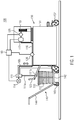
- Fig. 1 shows schematically a side view of a glue supply device for a labeling unit with an exchangeable storage container for glue according to the present invention.
- the figure shows the glue supply device 100 in combination with a modular labeling unit 150.
- the glue supply device is firmly connected to the labeling unit 150 and forms a module which is movably mounted on rollers 152 and which can be attached to a container table (not shown), for example. can be employed for container transport.
- the labeling unit 150 is in the Figure 1 shown only as a frame 151, which is mounted on rollers 152, but can in particular be used in connection with Figure 9 Have units and devices described.
- the labeling unit 150 also has a glue application unit in the form of a glue printer 119.
- the labeling unit 150 can have a guide handle 123 for moving the unit.
- the glue printer 119 is supplied with glue from an exchangeable storage container 110 by the glue supply device.
- the storage container 110 stands on a mobile container trolley 140.
- the container trolley 140 also has a guide rod 144 by means of which the container trolley 140, which is mounted on rollers 143, can be attached to the labeling unit 150 without great effort can be approached.
- the guide rod 144 can be connected to a receiving device 142 in such a way that a storage container 110 has a Leverage can be recorded and raised in a simple manner.
- the storage container 110 that is carried along can be parked or docked at a corresponding connection point, for example a connection plate (not shown), of the labeling unit 150.
- the storage container 110 can remain on the container trolley 140 as shown. This enables the storage container 110 to be changed in a particularly energy-saving and simple manner.
- the storage container 110 has a level indicator 112 in the form of a sight glass, from which the level of glue in the storage container can be read.
- the glue is pumped from the storage container 110 via the suction opening 111b of a suction pipe 111a by means of a glue pump 111 which is driven by a motor 114, in particular a controllable servomotor, into the supply line 116.
- a gear pump at the lower end of a riser pipe can be lowered into the storage container, which is driven by a controllable motor.
- the motor 114 is connected to a regulating or control unit 160 of the glue supply device 100 shown, which receives as input signals, for example, the volume flow of glue in the supply line 116 determined by a flow measuring device 126 and the glue pressure determined by a pressure sensor 125 located directly on the glue printer 119.
- the control and / or regulating unit 160 regulates the pump output of the glue pump 111 in order to continuously convey glue to the glue printer 119 with a glue pressure that is as constant as possible .
- a hydropneumatic accumulator 117 for example in the form of a membrane accumulator, is arranged at the inlet to the glue printer and is fluidically connected to the feed line 116.
- the hydropneumatic accumulator can in particular be arranged close to the glue printer 119.
- the glue printer 119 can be hydraulically decoupled from the glue pump 111, so that pressure fluctuations generated by the glue pump are not or only partially passed on to the glue printer. In this way an even glue pattern can be guaranteed.
- the hydropneumatic accumulator 117 can also be connected to the control and / or regulating unit 160.
- the hydropneumatic accumulator 117 can have a control valve (not shown) which is connected to a source for a filling gas, for example nitrogen, and limits the maximum pressure in the gas space of the hydropneumatic accumulator.
- a control valve not shown
- the control and / or regulating unit 160 can control the regulating valve in such a way that the required amount of gas is always present in the gas space of the hydropneumatic accumulator.
- both the supply line 116 and the sensors 125 and 126, the hydropneumatic accumulator 117 and the control and / or regulating unit 160 are permanently connected to the labeling unit 150.
- the elements mentioned can also be designed as part of a modular glue supply device which can be coupled to a separately designed labeling unit.
- a height-adjustable holding device 165 is also provided for the glue pump 111 and the motor 114, which is firmly connected to the labeling unit 150. With the aid of the holding device 165, the suction opening 111b can be dipped into the glue present in the storage container 110 and, after the storage container has been emptied, moved out of it again. The empty storage container can then be easily exchanged by the operator.
- Fig. 2 shows the arrangement of a hydropneumatic accumulator in the inlet to the glue printer according to the present invention.
- the further development shown shows the lower part of a pallet carousel 130 on which a large number of pivotably mounted pallets, which are not shown for the sake of clarity, are moved in a revolving manner. As they circulate, the pallets pass at a short distance the glue printer 119, which is provided with a large number of glue nozzles and applies the desired glue pattern either to a glue application surface of the pallets or directly to the back of labels carried by the pallets.
- the glue nozzles can be controlled individually via a control unit 127 of the glue printer 119.
- the glue printer 119 is supplied with glue via a feed line in the form of an elastic hose 116.
- a hydropneumatic accumulator 117 is arranged on the supply line 116 in the immediate vicinity of the glue printer. As described, this can have a volume of the liquid space in the range from 0.1 l to 1 l.
- the glue printer 119 is connected to the pallet carousel and / or the labeling unit 150 via a holder 118.
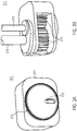
- the Figures 3A and 3B show a glue pump 311 in accordance with the present invention.
- the glue pump 311 shown is an external gear pump in which the gear wheels 375 are arranged in a housing 371 which encloses a delivery chamber of the pump.
- the housing 371 has a glue inlet opening 372 on its underside which the glue can enter into the delivery chamber of the pump.
- a sealing ring 373 is arranged on the underside of the housing 371, with which the glue inlet opening 372 can be sealed off from the interior of an additional tank surrounding the housing 371, as described in more detail below.
- the gears 375 are driven via a shaft arranged in a shaft housing 374 and driven by a motor (not shown) in such a way that the glue that has entered the delivery chamber of the glue pump 311 via the glue inlet opening 372 is conveyed into the riser pipe 376.
- the riser pipe 376 can in particular be connected to the above-mentioned supply line.
- Fig. 4 shows the glue pump 311 lowered into the storage container 310.
- the storage container 310 is designed as a bucket with handles on the upper edge.
- the only schematically indicated gears of the glue pump 311 are driven via the above-mentioned shaft by a controllable servomotor 314 which is arranged outside of the storage container 310. By moving the motor 314 and the glue pump 311 together vertically, the glue pump 311 can be moved out of the storage container 310 so that it can be changed.
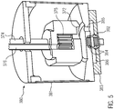
- Fig. 5 shows the additional tank 380 surrounding the glue pump 311 in a floating position when changing the storage container 310.
- the housing surrounding the gears 375 is designed to be movable relative to the additional tank 380 together with the shaft housing 374 and the riser pipe 376.
- the glue pump 311 is brought into contact with an upper part, for example a cover, of the additional tank 380 via spacers, which are arranged, for example, on the shaft housing 374 can be positioned relatively within the interior of the additional tank 380 in such a way that a large part of the glue located in the additional tank can be sucked off via the glue inlet opening 372 of the glue pump.
- the glue pump, and in particular the spacer is designed such that the glue inlet opening 372 is located in the floating position of the additional tank in the lower third, preferably in the lower quarter, of the interior volume of the additional tank.
- the interior volume of the additional tank 380 thus serves as a buffer store for glue during the replacement process for the storage container.
- the interior volume can in particular be at least 0.3 l, preferably at least 1 l, so that an operator has sufficient time to replace the storage container and lower the glue pump back into the storage container.
- the completely or partially emptied additional tank 380 can be refilled with glue when it is lowered into the glue located in the new storage container.
- the additional tank 380 can have one or more inlet openings through which glue can enter the additional tank in the upper area of the tank wall 381 or in a cover area of the additional tank.
- this is achieved in an elegant way in that the bores in the cover of the additional tank for the shaft housing 374 and the riser pipe 376 are wider than the cross section of the respective pipe so that glue can flow in through these openings.
- the constant relative movement of the shaft housing and the riser pipe also ensures that the openings are not clogged with hardened glue.
- the dimensions of the additional tank 380 in particular its overall height and / or the arrangement of the inlet openings, can be selected with regard to the dimensions and the usual filling height of completely filled storage containers in such a way that the additional tank is reliably filled with glue via the inlet openings after it has been lowered to the bottom of the storage container .
- the additional tank 380 has a bore 385 in its tank bottom 383, which connects the interior of the additional tank to the outside of the additional tank, i.e. the storage volume of the storage container 310, via a glue channel 386 in the bottom of the additional tank, which is here annular.
- a movable valve element 382 is arranged in the glue channel 386, which valve element is designed in such a way that it closes the glue channel and thus the connection to the outside space of the additional tank when the additional tank 380 is floating.
- the special valve element 382 shown here has a plug-shaped basic shape for this purpose and also has a permanent magnet 384, which interacts repulsively with a permanent magnet 384 of the same polarity and correspondingly arranged on the opposite side of the glue channel 386.
- the plug-shaped valve element 382 has at its lower end an extension which projects beyond the base plate 383 of the additional tank 380 and which can be brought into mechanical contact with the base of the storage container. The repulsive interaction of the magnets 384 pushes the valve element 382 into a closed position as long as the additional tank floats freely and in particular the lower extension of the valve element is not in mechanical contact with the bottom of the reservoir.
- the additional tank 380 is thus closed at the bottom by the valve element 382, so that the glue pump 311 can pump out the glue located in the additional tank via the glue inlet opening 372.
- the arrangement of the glue pump in the interior of the additional tank 380 in the floating position is selected in particular so that a sufficient distance, e.g. B. at least 1 cm, remains from the bottom of the additional tank, so that the glue located in the additional tank can enter the delivery chamber of the glue pump via the glue inlet opening 372.
- a return spring can be provided which presses the valve element into the closed position.
- the arrangement and design of the bore 385 and the glue channel 386 can also be varied as long as the bore 385, as mentioned in more detail below, faces the lower opening of the glue inlet opening 372 in the vertical direction.
- the glue channel 386 can be completely dispensed with if the valve element 382 is arranged directly in the bore 385.
- Fig. 6 shows the additional tank 380 after it has been lowered to the bottom of the storage container (not shown).
- the extension at the lower end of the valve element 382 is brought into contact with the bottom of the reservoir 310.
- the valve element 382 is pressed upwards from the closed position against the resistance of the repulsive interaction of the magnets 384 into an open position in which glue can enter the interior of the additional tank 380 via the glue channel 386 and the bore 385.
- the glue pump 311 can thus already convey glue from the storage container indirectly via the interior of the additional tank 380.
- a sufficient free space for example with a height of at least 1 cm, can be formed between the bottom of the storage container and the bottom of the additional tank, so that glue reliably from the Reservoir can be removed.
- Fig. 7 shows the additional tank 380 with completely lowered glue pump 311 in the operating state.
- the additional tank 380 is not displaced any further in the vertical direction, since it is already resting on the bottom of the storage container 310.
- the glue pump 311 is now lowered within the additional tank 380 to such an extent that the bottom area of the glue pump 311 is brought into mechanical contact with the bottom of the additional tank 380. So that a close contact can be established, can the bottom 383 of the additional tank 380 in particular as in FIG Figure 6 shown have a recess which corresponds in shape to the bottom area of the housing 371 of the glue pump.
- Figure 3A Sealing ring 373 shown are pressed against a flat surface of the bottom 383 of the additional tank. In this way, the glue inlet opening 372 of the glue pump is sealed off from the interior of the additional tank, so that no more glue is conveyed out of the additional tank.
- the glue inlet opening 372 is brought into congruent contact with the upper opening of the bore 385, so that the glue inlet opening 372, bore 385 and glue channel 386 have a continuous, the outer space of the additional tank 380 with the delivery space the supply line 387 connecting the glue pump 311.
- this is used to convey glue from the storage container 310 into the riser pipe 376.
- valve element 382 remains in an open position in the operating condition due to continued contact with the bottom of the reservoir.
- the additional tank 380 thus efficiently provides a glue buffer from which glue can be conveyed during the replacement process. This prevents the glue pump from running empty and the production interruption associated with it. The usual pressure fluctuations when starting up the glue pump are also eliminated.
- Fig. 8 shows a holding device 165, connected to the labeling unit 150, for the glue pump 111.
- the glue supply device shown together with the labeling unit 150 is shown in a three-dimensional view.
- the frame 151 of the labeling unit 150 has a connecting plate 163 to which the storage container 110 can be positioned or coupled.
- the holding device 165 which is connected to the labeling unit 150 and which in particular carries the motor 114 and the glue pump 111. As indicated schematically, the latter is surrounded by the additional tank 380 and has already been lowered to the bottom of the storage container 110.
- the holding device 165 comprises a telescopic rail 166, on which a cylinder provided with handles 169 with a gas pressure spring 167 is arranged adjustable in height. Due to the gas pressure spring 167, the holder 168, which carries the motor 114 and the glue pump 111, can also be moved vertically without great effort. whereby the glue pump can be lowered into the storage container 110 and driven out of the storage container to change the storage container.
- the holding device 165 attached to the labeling unit 150 thus further increases the ergonomics of the glue supply device.
- Fig. 9 schematically shows a further development of a glue supply device 200 not according to the invention.
- the storage container 210 is permanently connected to the labeling unit 250.
- the glue supply device 200, together with the labeling unit 250, thus forms a module which, as shown, can in particular be mounted on rollers 252 such that it can be moved.
- the labeling unit 250 has a frame 251 on which further components, such as a guide handle 223, can be arranged.
- the pallet carousel 230 with a large number of pallets 220 and a label unit 232 with a label container 231 for storing the labels to be glued are explicitly shown. These components are well known in the art and are therefore not described further here. The components can also be used in connection with Figure 1 described further development be provided.
- a holder 218 is arranged on the pallet carousel 230 or on the frame 251 and holds the glue printer 219, in particular in a height-adjustable manner.
- the glue printer is connected via an elastic supply line 216 to the motor 214 of a glue pump 211 which, as shown in the figure, has been lowered to the bottom of the storage container 210.
- the arrangement is selected in such a way that sufficient free space is available for sucking in glue. Since the storage container 210 is firmly connected to the labeling unit 250 in this development, a height-adjustable holding device can be dispensed with. Instead, the upper region of the storage container 210 has a lid 215 which can be opened to refill the storage container.
- the glue pump can thus be designed in the form of a gear pump which is controllably driven by the motor 214.
- the same developments that were described in connection with the previous figures for the glue pump, the feed line, the control and / or regulating unit (not shown), the sensors, ie flow measuring device, pressure sensor and temperature sensor, and the like, can also be applied to the in Figure 9 Apply the further training presented.
- the storage container 210 has a level indicator in the form of a level tube 212 or level sensors 222.
- the feed line can also have the heating device described above.
- Such a device can, however, also be arranged inside or on the storage container 210.
- the hydropneumatic accumulator 217 already described is arranged on the supply line 216.
- Figure 9 a safety valve with a return line 221, via which glue can be passed from the supply line 216 back into the storage container 210 when a limit value for the glue pressure is exceeded.
- the safety valve is designed in such a way that it opens automatically when the limit pressure is exceeded.
- Such a safety valve with return line can also be used in connection with Figure 1 described training are used.
- the storage container 210 has a drain cock 213 in the lower area of the container wall for manually draining the glue from the storage container, should this be necessary, for example for cleaning the storage container.
- the illustrated development with a storage container fixedly attached to the labeling unit can be used particularly advantageously for glue with a low viscosity, for example in the range from 10 to 100 mPas, since these can be easily refilled into the storage container using a canister. Due to the smaller container size, only small loads have to be moved, which contributes to the ergonomics of the use of the system.
- Fig. 10 shows schematically a top view of a labeling device of the prior art, which can be used in connection with the labeling units and glue supply devices described above.
- the illustrated labeling device 400 comprises a transport device designed as a container table 494, along which the containers 493 or bundles to be labeled run on a plurality of rotatable holders (not shown) on a curved path.
- a pretreatment unit 495 which prepares the container 493 to be labeled for labeling by cleaning the container surface to be labeled, pre-moistening or blowing, heating and / or radiation and / or plasma and / or subject to corona treatment.
- sensors 409 and 497 can be provided which monitor the condition of the surface to be labeled, e.g. B. smooth, rough, etc., and / or environmental conditions such. B.
- a rolling-on unit 434 and / or a brushing-on unit 435 can be provided after the labeling position 498 in order to wrap the label 499 placed on the container fully apply and press down.
- the containers provided with the label 436 are then transferred to a subsequent treatment station, for example a filling station for filling with a liquid food.
- the labeling unit shown in the exemplary labeling machine comprises a pallet carousel 430 with a multiplicity of pallets 404, 405 and 420 rotating about an axis of rotation of the pallet carousel, which in turn are designed to be pivotable about their own eccentrically mounted pivot axes 406.
- the pallets On their outwardly facing side, the pallets have a contact surface 408 which can be made large enough that it can accommodate a large number of different label formats.
- the initially unloaded pallet 404 is guided past a label storage 431 arranged on the periphery of the pallet carousel in the form of a label box during its rotation around the axis of rotation of the pallet carousel 430 and is swiveled so that the contact surface 408 of the pallet is the foremost label 402 of the label box 431 takes over. Since the pallets can be designed as vacuum pallets, this transfer is reliably possible even without prior application of glue to the contact surface 408. In order to be able to adapt the distance between the foremost label 402 and the pallet carousel 430, the label box 431 can be designed to be switchable via a pneumatic cylinder 401.
- the labels 402 are provided with their image side facing forward, they also come to lie with the image side on the contact surface 408 of the pallet 405.
- the glue application surface 492 of the labels 407 transported by the pallets 405 and 420 faces away from the contact surface of the respective pallet.
- the glue application surface of the label 407 which thus faces outwards, can therefore be glued directly on the pallet by means of a gluing unit 403 arranged on the orbit of the pallets 404, 405 and 420, ie on the periphery of the pallet carousel 430.
- a gluing unit 403 according to the inkjet method is shown.
- the cold glue is sprayed directly onto the glue application surface 492 from a plurality of glue nozzles in the form of a glue jet 491.
- the glue application surface 492 is guided past the openings of the glue nozzles by rotating and pivoting the pallet 420, preferably at a constant distance.
- the glue nozzles for example according to the DoD principle (drop-on-demand)
- almost any glue pattern can be printed onto the glue application surface 492 in superimposition with the pallet movement.
- the exact amount of cold glue required can be printed on, so that a glue return can be completely dispensed with.
- the supply of glue to the glue printer 419 via the glue supply line 416 can take place in a controlled manner in the required amount by means of one of the glue supply devices described above.
- the Figure 10 shows only the glue supply line 416 and a schematic representation of the glue pump 411 representative of the glue supply devices described above.
- the labels are placed directly from the pallets 404, 405 and 420 onto the containers 493, which are guided past the labeling position 498, and are wound onto them by rotating the holders of the container table 494.
- the pallets are moved past the container surfaces and swiveled in such a way that the labels carried along are rolled onto the container surfaces in combination with the rotating movement of the containers and their rotation around the container table.
- a slip-free rolling of the labels onto the container surfaces can be achieved so that the applied labels do not slip unintentionally.
- the circulating movements of the pallets 404, 405 and 420 and the holders of the container table 494 can be controlled by means of controllable drives (not shown) via the control and / or regulating unit 460 of the labeling device 400.
- the rotary movement of the holders for the containers can also be controlled and / or regulated by means of the control and / or regulating unit, for example via individually provided servomotors.
- the pivoting movements of the pallets 404, 405 and 420 can be controlled and / or regulated by means of the control and / or regulating unit via corresponding control cams or also via servomotors specially provided for this purpose.
- the vacuum supply and the glue nozzles can be controlled via the control and / or regulating unit 460 as described above.
- the control and / or regulating unit can in particular be a programmable logic control unit which has a memory unit, for example in the form of a flash memory, in which the memory parameters required for control, e.g. B. in relation to the desired glue pattern are stored.
- a common control and / or regulating unit 460 can be provided for the labeling device 400 and the glue supply device.
- the glue supply devices described above can also be applied to labeling devices of different design.
- the positions of the label box 431 and the gluing station 403 can be interchanged, so that a defined glue pattern is first applied to a glue application surface 408 of the pallets 404, which is then brought into contact with a rear side of the labels 402.
- the image side of the labels is then transferred to a gripper cylinder as is generally known in the prior art.
- the labels are finally applied to the containers 493 by means of the gripper cylinder.
- the glue supply devices described above allow the application of a well-defined glue pattern with an approximately constant glue pressure without the otherwise usual production interruptions for changing the storage container for the glue.
- the closed glue supply system also improves the durability of the cold glue. Since the amount of cold glue applied can now be precisely adjusted, there is no need to transport excess cold glue back. If a cold glue with low viscosity is used, the energy consumption of the labeling unit can also be reduced.
Landscapes
- Coating Apparatus (AREA)
- Labeling Devices (AREA)
Claims (12)
- Dispositif d'alimentation en colle pour groupe d'étiquetage (150, 250, 400) avec applicateur de colle (119, 219, 419), comprenant :un récipient de stockage (110, 210) pour de la colle, en particulier de la colle à froid de faible viscosité,une conduite d'acheminement (116, 216) permettant d'acheminer de la colle en provenance du réservoir vers l'applicateur de colle, etun réservoir hydropneumatique (117, 217) pour la colle,dans lequel le réservoir hydropneumatique est agencé au niveau de la conduite d'acheminement avant l'applicateur de colle ;caractérisé parune pompe à colle (111, 211, 311, 411) transportant en continu et conçue pour transporter de la colle en provenance du récipient de stockage jusque dans la conduite d'acheminement, etune cuve auxiliaire (380), dans lequel la cuve auxiliaire est reliée mécaniquement à la pompe à colle (111, 311, 411) de telle manière que la cuve auxiliaire, qui est sinon agencée à l'intérieur du récipient de stockage, peut être sortie du récipient de stockage avec la pompe à colle en vue d'un échange du récipient de stockage (110), et de telle manière que de la colle est retirée de la cuve auxiliaire au moyen de la pompe à colle lors de l'échange du récipient de stockage (110).
- Dispositif d'alimentation en colle selon la revendication 1, dans lequel la pompe à colle (111, 211, 311, 411) est conçue comme une pompe à engrenages, en particulier comme une pompe à engrenages extérieure.
- Dispositif d'alimentation en colle selon la revendication 1 ou 2, dans lequel la pompe à colle (111, 211, 311, 411) est conçue pour pouvoir être régulée, et comprend en outre un appareil de mesure de pression (125) et une unité de commande et/ou de régulation (160, 460),
dans lequel l'appareil de mesure de pression (125) est agencé immédiatement avant ou au niveau de l'applicateur de colle (119, 219, 419) et est conçu pour déterminer la pression de colle préalablement à l'applicateur de colle, et
dans lequel l'unité de commande et/ou de régulation (160, 460) est conçue pour réguler la pompe à colle (111, 211, 311, 411) en fonction de la pression de colle déterminée. - Dispositif d'alimentation en colle selon l'une quelconque des revendications 1 à 3, comprenant en outre un moyen de retenue (165) conçu pour maintenir la pompe à colle (111, 211, 311, 411) sur le groupe d'étiquetage (150, 250, 400) de manière réglable en hauteur.
- Dispositif d'alimentation en colle selon la revendication 4, dans lequel le moyen de retenue (165) comprend un rail télescopique (166) et un cylindre muni d'un ressort à gaz (167) permettant le réglage en hauteur de la pompe à colle (111, 211, 311, 411).
- Dispositif d'alimentation en colle selon l'une quelconque des revendications précédentes, dans lequel la cuve auxiliaire (380) entoure la pompe à colle (111, 311, 411) et présente un élément formant soupape (382) conçu pour ouvrir et sinon pour fermer la cuve auxiliaire en contact avec un fond du récipient de stockage (110).
- Dispositif d'alimentation en colle selon la revendication 6, dans lequel ladite pompe à colle (111, 311, 411) est conçue pour pouvoir coulisser par rapport à un fond (383) de la cuve auxiliaire (380).
- Dispositif d'alimentation en colle selon la revendication 7, dans lequel le fond (383) de la cuve auxiliaire (380) présente un alésage (385), et dans lequel, grâce à l'abaissement de la pompe à colle (111, 311, 411) avec une ouverture d'alimentation en colle (372) correspondante de la pompe à colle, l'alésage forme une conduite d'alimentation (387), pouvant être fermée par l'intermédiaire de l'élément formant soupape (382), pour de la colle en provenance du récipient de stockage (110).
- Dispositif d'alimentation en colle selon l'une quelconque des revendications précédentes, dans lequel le récipient de stockage (110) est conçu pour pouvoir être échangé, en particulier comme un module mobile (140), et comprend en outre un appareil de réception mécanique (163), en particulier une plaque de liaison, permettant de coupler le récipient de stockage (110) au groupe d'étiquetage (150).
- Dispositif d'alimentation en colle selon l'une quelconque des revendications précédentes, dans lequel une soupape de sécurité (221) est en outre agencée sur la conduite d'acheminement (216) qui est conçue pour ouvrir un drain en cas de dépassement d'une pression limite au sein de la conduite d'alimentation.
- Groupe d'étiquetage (150, 250, 400) permettant d'apposer des étiquettes sur des récipients, comprenant :un carrousel à palettes (130, 230, 430) avec une pluralité de palettes (220, 420) pouvant être entraînées en circulation autour d'un axe de rotation,un applicateur de colle (119, 219, 419) agencé à la périphérie du carrousel à palettes et muni d'une pluralité de buses à colle pouvant être commandées individuellement ou en groupes, etun dispositif d'alimentation en colle selon l'une quelconque des revendications précédentes permettant d'alimenter de manière continue en colle, en particulier en colle à froid, l'applicateur de colle.
- Utilisation d'un dispositif d'alimentation en colle (100) selon la revendication 9, dans laquelle la pompe à colle (111) et la cuve auxiliaire (380) sont sortis du récipient de stockage au moyen d'un dispositif de retenue (165) afin d'échanger le récipient de stockage (110), et dans laquelle un récipient de stockage rempli est déplacé vers le dispositif d'alimentation en colle au moyen d'un chariot à récipient (140).
Applications Claiming Priority (1)
| Application Number | Priority Date | Filing Date | Title |
|---|---|---|---|
| DE102017219496.0A DE102017219496A1 (de) | 2017-11-02 | 2017-11-02 | Leimversorgung für Etikettieraggregat mit Leimdrucker |
Publications (2)
| Publication Number | Publication Date |
|---|---|
| EP3483080A1 EP3483080A1 (fr) | 2019-05-15 |
| EP3483080B1 true EP3483080B1 (fr) | 2021-06-23 |
Family
ID=63798897
Family Applications (1)
| Application Number | Title | Priority Date | Filing Date |
|---|---|---|---|
| EP18199300.7A Active EP3483080B1 (fr) | 2017-11-02 | 2018-10-09 | Alimentation en colle pour groupe d'étiquetage pourvu d'un applicateur de colle |
Country Status (4)
| Country | Link |
|---|---|
| US (1) | US10703524B2 (fr) |
| EP (1) | EP3483080B1 (fr) |
| CN (1) | CN209667557U (fr) |
| DE (1) | DE102017219496A1 (fr) |
Families Citing this family (7)
| Publication number | Priority date | Publication date | Assignee | Title |
|---|---|---|---|---|
| DE202017105400U1 (de) * | 2017-09-07 | 2018-12-10 | Krones Ag | Heißleimwerk für eine Etikettiermaschine mit Absaugung |
| DE102020124411A1 (de) | 2020-09-18 | 2022-03-24 | Krones Aktiengesellschaft | Leimdrucker für Etikettieraggregat |
| JP7851336B2 (ja) * | 2021-06-16 | 2026-04-24 | スリーエム イノベイティブ プロパティズ カンパニー | 接着剤分注のシステム及び方法 |
| DE102022123054A1 (de) * | 2022-09-09 | 2024-03-14 | Krones Aktiengesellschaft | Verfahren zur Produktionsüberwachung einer Etikettiermaschine und Etikettiermaschine zur Etikettierung von Behältern |
| DE102022123055A1 (de) * | 2022-09-09 | 2024-03-14 | Krones Aktiengesellschaft | Verfahren zur Produktionsüberwachung einer Etikettiermaschine und Etikettiermaschine zur Etikettierung von Behältern |
| KR102665488B1 (ko) * | 2022-12-12 | 2024-05-10 | (주)시화 | 봉함용지 생산용 글루순환 공급 장치 |
| CN116493204B (zh) * | 2023-06-30 | 2023-08-18 | 常州铭赛机器人科技股份有限公司 | 供胶系统及供胶方法 |
Family Cites Families (19)
| Publication number | Priority date | Publication date | Assignee | Title |
|---|---|---|---|---|
| US3104986A (en) * | 1960-08-08 | 1963-09-24 | Robert L Goman | Fluid dispensing system |
| DE6603935U (de) * | 1967-09-07 | 1969-12-04 | Hermann Kronseder | Klebstoffzufuehrung in etikettiermaschinen |
| DE9313524U1 (de) * | 1993-09-09 | 1993-10-28 | Kronseder, Hermann, 93086 Wörth | Vorrichtung zur Leimversorgung von Etikettiermaschinen |
| DE4423651A1 (de) * | 1994-07-06 | 1996-01-11 | Zahnradfabrik Friedrichshafen | Antriebseinrichtung für ein Kraftfahrzeug, insbesondere eine Baumaschine |
| DE19515295A1 (de) * | 1995-04-26 | 1996-10-31 | Hemscheidt Fahrwerktech Gmbh | Hydropneumatisches Federungssystem |
| DE19844493A1 (de) * | 1998-09-29 | 2000-03-30 | Zahnradfabrik Friedrichshafen | Hydropneumatisches Federungssystem |
| FR2821393B1 (fr) * | 2001-02-26 | 2005-10-28 | Eca | Actionneur compense a puissance optimisee |
| DE10116235A1 (de) * | 2001-03-31 | 2002-10-17 | Hydac Technology Gmbh | Hydropneumatischer Druckspeicher |
| US20080084111A1 (en) * | 2004-08-11 | 2008-04-10 | Johann Rainer | Traveling Mechanism for Agricultural Machines and Off-Road Vehicles Having an Endless Belt -Band Traveling Gear and a Corresponding Belt-Band Traveling Gear |
| DE102005061991A1 (de) * | 2005-12-23 | 2007-07-05 | Bosch Rexroth Aktiengesellschaft | Hydrostatischer Antrieb |
| DE102007002675A1 (de) * | 2007-01-18 | 2008-07-31 | Khs Ag | Etikettieraggregat |
| FR2930014B1 (fr) * | 2008-04-14 | 2010-05-28 | Charlatte Reservoirs | Dispositif et procede d'introduction d'air dans un reservoir hydropneumatique |
| WO2011123503A1 (fr) * | 2010-04-01 | 2011-10-06 | B & H Manufacturing Company, Inc. | Système d'application d'extrusion |
| EP2404771A1 (fr) * | 2010-07-06 | 2012-01-11 | HEMSCHEIDT FAHRWERKTECHNIK GmbH & Co. KG | Stockeur de piston hydropneumatique |
| DE102011003060A1 (de) * | 2011-01-24 | 2012-07-26 | Krones Aktiengesellschaft | Leimzuführeinrichtung und Etikettiermaschine |
| DE102011089607B4 (de) * | 2011-12-22 | 2023-07-13 | Robert Bosch Gmbh | Verfahren zum Betrieb eines seriellen hydraulischen Hybridantriebssystems |
| DE102012106185B3 (de) * | 2012-07-10 | 2013-11-21 | Fsp Fluid Systems Partners Holding Ag | Steueranordnung für ein hydropneumatisches Federungssystem sowie hydropneumatisches Federungssystem mit einer solchen Steueranordnung |
| DE102015212140A1 (de) | 2015-06-30 | 2017-01-05 | Krones Ag | Vorrichtung und Verfahren zum Etikettieren von Behältern |
| DE102015212198A1 (de) | 2015-06-30 | 2017-01-05 | Krones Ag | Vorrichtung und Verfahren zum Leimauftrag ohne Rücklauf |
-
2017
- 2017-11-02 DE DE102017219496.0A patent/DE102017219496A1/de active Pending
-
2018
- 2018-10-09 EP EP18199300.7A patent/EP3483080B1/fr active Active
- 2018-11-01 US US16/177,940 patent/US10703524B2/en active Active
- 2018-11-01 CN CN201821791815.6U patent/CN209667557U/zh active Active
Non-Patent Citations (1)
| Title |
|---|
| None * |
Also Published As
| Publication number | Publication date |
|---|---|
| DE102017219496A1 (de) | 2019-05-02 |
| US20190127104A1 (en) | 2019-05-02 |
| US10703524B2 (en) | 2020-07-07 |
| CN209667557U (zh) | 2019-11-22 |
| EP3483080A1 (fr) | 2019-05-15 |
Similar Documents
| Publication | Publication Date | Title |
|---|---|---|
| EP3483080A1 (fr) | Alimentation en colle pour groupe d'étiquetage pourvu d'un applicateur de colle | |
| EP3317189B1 (fr) | Dispositif et procédé pour étiqueter des récipients | |
| EP2982487B1 (fr) | Appareil de changement de l'outil inferieur et superieur d'une machine d'emballage | |
| EP3317192B1 (fr) | Rouleau d'encollage avec zone de collage limité | |
| EP1520833B1 (fr) | Machine de remplissage | |
| EP3317191A1 (fr) | Dispositif et procédé d'application de colle sans élément de retour | |
| EP2144830B1 (fr) | Procédé et dispositif pour emballer des grands emballages pour bouteilles | |
| DE102015212136A1 (de) | Vorrichtung und Verfahren zum Etikettieren von Behältern | |
| EP3621752A1 (fr) | Remplisseuse conçue pour remplir des sacs ouverts de produits en vrac et dispositif de nettoyage | |
| WO2011128439A1 (fr) | Système d'application pour milieux liquides | |
| EP3908464B1 (fr) | Applicateur avec dispositif de positionnement | |
| DE2918054A1 (de) | Sirupzufuehrvorrichtung fuer ein getraenkeabgabegeraet mit nachmischung | |
| EP3486185A1 (fr) | Alimentation en colle centralisée pour une machine d'étiquetage des récipients | |
| EP1072492B1 (fr) | Dispositif et procédé pour transférer d'un produit en vrac dans un consommateur | |
| EP2780121B1 (fr) | Dispositif destiné à introduire des arômes dans un milieu | |
| EP0836995A1 (fr) | Procédé et dispositif pour emballer des boítes ou des tubes | |
| EP1642830B1 (fr) | Installation de remplissage de produits fluides ou pâteux, par exemple des produits alimentaires | |
| WO2022058052A1 (fr) | Imprimante à colle pour étiqueteuse | |
| DE4314400C2 (de) | Vollautomatische Füll- und Verschließmaschine | |
| DE102006049160B3 (de) | Lagervorrichtung für lose zuführbare Gegenstände | |
| EP2259927A1 (fr) | Alimentation en encre ménageant l'encre de machines à imprimer | |
| EP3908466A1 (fr) | Groupe applicateur avec arrangement de positionnement et dispositif d'accumulation | |
| DE4242493A1 (de) | Vorrichtung zur Entnahme von Farbe | |
| DE102010046818B3 (de) | Fettpresse, insbesondere für eine Fettschmieranlage und Verfahren zum Zuführen von Fett zu einer mit Fett zu schmierenden Vorrichtung | |
| DE102019100308A1 (de) | Auftragaggregat mit Positioniervorrichtung und Speichereinrichtung |
Legal Events
| Date | Code | Title | Description |
|---|---|---|---|
| PUAI | Public reference made under article 153(3) epc to a published international application that has entered the european phase |
Free format text: ORIGINAL CODE: 0009012 |
|
| STAA | Information on the status of an ep patent application or granted ep patent |
Free format text: STATUS: THE APPLICATION HAS BEEN PUBLISHED |
|
| AK | Designated contracting states |
Kind code of ref document: A1 Designated state(s): AL AT BE BG CH CY CZ DE DK EE ES FI FR GB GR HR HU IE IS IT LI LT LU LV MC MK MT NL NO PL PT RO RS SE SI SK SM TR |
|
| AX | Request for extension of the european patent |
Extension state: BA ME |
|
| STAA | Information on the status of an ep patent application or granted ep patent |
Free format text: STATUS: REQUEST FOR EXAMINATION WAS MADE |
|
| 17P | Request for examination filed |
Effective date: 20191112 |
|
| RBV | Designated contracting states (corrected) |
Designated state(s): AL AT BE BG CH CY CZ DE DK EE ES FI FR GB GR HR HU IE IS IT LI LT LU LV MC MK MT NL NO PL PT RO RS SE SI SK SM TR |
|
| GRAP | Despatch of communication of intention to grant a patent |
Free format text: ORIGINAL CODE: EPIDOSNIGR1 |
|
| STAA | Information on the status of an ep patent application or granted ep patent |
Free format text: STATUS: GRANT OF PATENT IS INTENDED |
|
| INTG | Intention to grant announced |
Effective date: 20210119 |
|
| GRAS | Grant fee paid |
Free format text: ORIGINAL CODE: EPIDOSNIGR3 |
|
| GRAA | (expected) grant |
Free format text: ORIGINAL CODE: 0009210 |
|
| STAA | Information on the status of an ep patent application or granted ep patent |
Free format text: STATUS: THE PATENT HAS BEEN GRANTED |
|
| AK | Designated contracting states |
Kind code of ref document: B1 Designated state(s): AL AT BE BG CH CY CZ DE DK EE ES FI FR GB GR HR HU IE IS IT LI LT LU LV MC MK MT NL NO PL PT RO RS SE SI SK SM TR |
|
| REG | Reference to a national code |
Ref country code: GB Ref legal event code: FG4D Free format text: NOT ENGLISH |
|
| REG | Reference to a national code |
Ref country code: CH Ref legal event code: EP |
|
| REG | Reference to a national code |
Ref country code: DE Ref legal event code: R096 Ref document number: 502018005800 Country of ref document: DE Ref country code: AT Ref legal event code: REF Ref document number: 1404131 Country of ref document: AT Kind code of ref document: T Effective date: 20210715 |
|
| REG | Reference to a national code |
Ref country code: IE Ref legal event code: FG4D Free format text: LANGUAGE OF EP DOCUMENT: GERMAN |
|
| REG | Reference to a national code |
Ref country code: LT Ref legal event code: MG9D |
|
| PG25 | Lapsed in a contracting state [announced via postgrant information from national office to epo] |
Ref country code: FI Free format text: LAPSE BECAUSE OF FAILURE TO SUBMIT A TRANSLATION OF THE DESCRIPTION OR TO PAY THE FEE WITHIN THE PRESCRIBED TIME-LIMIT Effective date: 20210623 Ref country code: HR Free format text: LAPSE BECAUSE OF FAILURE TO SUBMIT A TRANSLATION OF THE DESCRIPTION OR TO PAY THE FEE WITHIN THE PRESCRIBED TIME-LIMIT Effective date: 20210623 Ref country code: LT Free format text: LAPSE BECAUSE OF FAILURE TO SUBMIT A TRANSLATION OF THE DESCRIPTION OR TO PAY THE FEE WITHIN THE PRESCRIBED TIME-LIMIT Effective date: 20210623 Ref country code: BG Free format text: LAPSE BECAUSE OF FAILURE TO SUBMIT A TRANSLATION OF THE DESCRIPTION OR TO PAY THE FEE WITHIN THE PRESCRIBED TIME-LIMIT Effective date: 20210923 |
|
| PG25 | Lapsed in a contracting state [announced via postgrant information from national office to epo] |
Ref country code: NO Free format text: LAPSE BECAUSE OF FAILURE TO SUBMIT A TRANSLATION OF THE DESCRIPTION OR TO PAY THE FEE WITHIN THE PRESCRIBED TIME-LIMIT Effective date: 20210923 Ref country code: LV Free format text: LAPSE BECAUSE OF FAILURE TO SUBMIT A TRANSLATION OF THE DESCRIPTION OR TO PAY THE FEE WITHIN THE PRESCRIBED TIME-LIMIT Effective date: 20210623 Ref country code: RS Free format text: LAPSE BECAUSE OF FAILURE TO SUBMIT A TRANSLATION OF THE DESCRIPTION OR TO PAY THE FEE WITHIN THE PRESCRIBED TIME-LIMIT Effective date: 20210623 Ref country code: SE Free format text: LAPSE BECAUSE OF FAILURE TO SUBMIT A TRANSLATION OF THE DESCRIPTION OR TO PAY THE FEE WITHIN THE PRESCRIBED TIME-LIMIT Effective date: 20210623 Ref country code: GR Free format text: LAPSE BECAUSE OF FAILURE TO SUBMIT A TRANSLATION OF THE DESCRIPTION OR TO PAY THE FEE WITHIN THE PRESCRIBED TIME-LIMIT Effective date: 20210924 |
|
| REG | Reference to a national code |
Ref country code: NL Ref legal event code: MP Effective date: 20210623 |
|
| PG25 | Lapsed in a contracting state [announced via postgrant information from national office to epo] |
Ref country code: RO Free format text: LAPSE BECAUSE OF FAILURE TO SUBMIT A TRANSLATION OF THE DESCRIPTION OR TO PAY THE FEE WITHIN THE PRESCRIBED TIME-LIMIT Effective date: 20210623 Ref country code: PT Free format text: LAPSE BECAUSE OF FAILURE TO SUBMIT A TRANSLATION OF THE DESCRIPTION OR TO PAY THE FEE WITHIN THE PRESCRIBED TIME-LIMIT Effective date: 20211025 Ref country code: NL Free format text: LAPSE BECAUSE OF FAILURE TO SUBMIT A TRANSLATION OF THE DESCRIPTION OR TO PAY THE FEE WITHIN THE PRESCRIBED TIME-LIMIT Effective date: 20210623 Ref country code: CZ Free format text: LAPSE BECAUSE OF FAILURE TO SUBMIT A TRANSLATION OF THE DESCRIPTION OR TO PAY THE FEE WITHIN THE PRESCRIBED TIME-LIMIT Effective date: 20210623 Ref country code: SK Free format text: LAPSE BECAUSE OF FAILURE TO SUBMIT A TRANSLATION OF THE DESCRIPTION OR TO PAY THE FEE WITHIN THE PRESCRIBED TIME-LIMIT Effective date: 20210623 Ref country code: SM Free format text: LAPSE BECAUSE OF FAILURE TO SUBMIT A TRANSLATION OF THE DESCRIPTION OR TO PAY THE FEE WITHIN THE PRESCRIBED TIME-LIMIT Effective date: 20210623 Ref country code: ES Free format text: LAPSE BECAUSE OF FAILURE TO SUBMIT A TRANSLATION OF THE DESCRIPTION OR TO PAY THE FEE WITHIN THE PRESCRIBED TIME-LIMIT Effective date: 20210623 Ref country code: EE Free format text: LAPSE BECAUSE OF FAILURE TO SUBMIT A TRANSLATION OF THE DESCRIPTION OR TO PAY THE FEE WITHIN THE PRESCRIBED TIME-LIMIT Effective date: 20210623 |
|
| PG25 | Lapsed in a contracting state [announced via postgrant information from national office to epo] |
Ref country code: PL Free format text: LAPSE BECAUSE OF FAILURE TO SUBMIT A TRANSLATION OF THE DESCRIPTION OR TO PAY THE FEE WITHIN THE PRESCRIBED TIME-LIMIT Effective date: 20210623 |
|
| REG | Reference to a national code |
Ref country code: DE Ref legal event code: R097 Ref document number: 502018005800 Country of ref document: DE |
|
| PG25 | Lapsed in a contracting state [announced via postgrant information from national office to epo] |
Ref country code: DK Free format text: LAPSE BECAUSE OF FAILURE TO SUBMIT A TRANSLATION OF THE DESCRIPTION OR TO PAY THE FEE WITHIN THE PRESCRIBED TIME-LIMIT Effective date: 20210623 |
|
| PLBE | No opposition filed within time limit |
Free format text: ORIGINAL CODE: 0009261 |
|
| STAA | Information on the status of an ep patent application or granted ep patent |
Free format text: STATUS: NO OPPOSITION FILED WITHIN TIME LIMIT |
|
| REG | Reference to a national code |
Ref country code: CH Ref legal event code: PL |
|
| 26N | No opposition filed |
Effective date: 20220324 |
|
| PG25 | Lapsed in a contracting state [announced via postgrant information from national office to epo] |
Ref country code: AL Free format text: LAPSE BECAUSE OF FAILURE TO SUBMIT A TRANSLATION OF THE DESCRIPTION OR TO PAY THE FEE WITHIN THE PRESCRIBED TIME-LIMIT Effective date: 20210623 |
|
| REG | Reference to a national code |
Ref country code: BE Ref legal event code: MM Effective date: 20211031 |
|
| PG25 | Lapsed in a contracting state [announced via postgrant information from national office to epo] |
Ref country code: MC Free format text: LAPSE BECAUSE OF FAILURE TO SUBMIT A TRANSLATION OF THE DESCRIPTION OR TO PAY THE FEE WITHIN THE PRESCRIBED TIME-LIMIT Effective date: 20210623 |
|
| PG25 | Lapsed in a contracting state [announced via postgrant information from national office to epo] |
Ref country code: LU Free format text: LAPSE BECAUSE OF NON-PAYMENT OF DUE FEES Effective date: 20211009 Ref country code: BE Free format text: LAPSE BECAUSE OF NON-PAYMENT OF DUE FEES Effective date: 20211031 |
|
| PG25 | Lapsed in a contracting state [announced via postgrant information from national office to epo] |
Ref country code: LI Free format text: LAPSE BECAUSE OF NON-PAYMENT OF DUE FEES Effective date: 20211031 Ref country code: CH Free format text: LAPSE BECAUSE OF NON-PAYMENT OF DUE FEES Effective date: 20211031 |
|
| PG25 | Lapsed in a contracting state [announced via postgrant information from national office to epo] |
Ref country code: IE Free format text: LAPSE BECAUSE OF NON-PAYMENT OF DUE FEES Effective date: 20211009 |
|
| GBPC | Gb: european patent ceased through non-payment of renewal fee |
Effective date: 20221009 |
|
| PG25 | Lapsed in a contracting state [announced via postgrant information from national office to epo] |
Ref country code: CY Free format text: LAPSE BECAUSE OF FAILURE TO SUBMIT A TRANSLATION OF THE DESCRIPTION OR TO PAY THE FEE WITHIN THE PRESCRIBED TIME-LIMIT Effective date: 20210623 |
|
| PG25 | Lapsed in a contracting state [announced via postgrant information from national office to epo] |
Ref country code: HU Free format text: LAPSE BECAUSE OF FAILURE TO SUBMIT A TRANSLATION OF THE DESCRIPTION OR TO PAY THE FEE WITHIN THE PRESCRIBED TIME-LIMIT; INVALID AB INITIO Effective date: 20181009 |
|
| PG25 | Lapsed in a contracting state [announced via postgrant information from national office to epo] |
Ref country code: GB Free format text: LAPSE BECAUSE OF NON-PAYMENT OF DUE FEES Effective date: 20221009 |
|
| PG25 | Lapsed in a contracting state [announced via postgrant information from national office to epo] |
Ref country code: MK Free format text: LAPSE BECAUSE OF FAILURE TO SUBMIT A TRANSLATION OF THE DESCRIPTION OR TO PAY THE FEE WITHIN THE PRESCRIBED TIME-LIMIT Effective date: 20210623 |
|
| PG25 | Lapsed in a contracting state [announced via postgrant information from national office to epo] |
Ref country code: TR Free format text: LAPSE BECAUSE OF FAILURE TO SUBMIT A TRANSLATION OF THE DESCRIPTION OR TO PAY THE FEE WITHIN THE PRESCRIBED TIME-LIMIT Effective date: 20210623 |
|
| PG25 | Lapsed in a contracting state [announced via postgrant information from national office to epo] |
Ref country code: MT Free format text: LAPSE BECAUSE OF FAILURE TO SUBMIT A TRANSLATION OF THE DESCRIPTION OR TO PAY THE FEE WITHIN THE PRESCRIBED TIME-LIMIT Effective date: 20210623 |
|
| PGFP | Annual fee paid to national office [announced via postgrant information from national office to epo] |
Ref country code: FR Payment date: 20240909 Year of fee payment: 7 |
|
| PGFP | Annual fee paid to national office [announced via postgrant information from national office to epo] |
Ref country code: IT Payment date: 20240910 Year of fee payment: 7 |
|
| REG | Reference to a national code |
Ref country code: AT Ref legal event code: MM01 Ref document number: 1404131 Country of ref document: AT Kind code of ref document: T Effective date: 20231009 |
|
| PGFP | Annual fee paid to national office [announced via postgrant information from national office to epo] |
Ref country code: DE Payment date: 20240904 Year of fee payment: 7 |
|
| PG25 | Lapsed in a contracting state [announced via postgrant information from national office to epo] |
Ref country code: AT Free format text: LAPSE BECAUSE OF NON-PAYMENT OF DUE FEES Effective date: 20231009 |
|
| PG25 | Lapsed in a contracting state [announced via postgrant information from national office to epo] |
Ref country code: AT Free format text: LAPSE BECAUSE OF NON-PAYMENT OF DUE FEES Effective date: 20231009 |
|
| PGFP | Annual fee paid to national office [announced via postgrant information from national office to epo] |
Ref country code: AT Payment date: 20260410 Year of fee payment: 5 |