EP3483391B1 - Pale de turbine d'une couronne de pale de turbine - Google Patents
Pale de turbine d'une couronne de pale de turbine Download PDFInfo
- Publication number
- EP3483391B1 EP3483391B1 EP18204562.5A EP18204562A EP3483391B1 EP 3483391 B1 EP3483391 B1 EP 3483391B1 EP 18204562 A EP18204562 A EP 18204562A EP 3483391 B1 EP3483391 B1 EP 3483391B1
- Authority
- EP
- European Patent Office
- Prior art keywords
- cooling air
- cross
- turbine blade
- sectional area
- sub
- Prior art date
- Legal status (The legal status is an assumption and is not a legal conclusion. Google has not performed a legal analysis and makes no representation as to the accuracy of the status listed.)
- Active
Links
Images



Classifications
-
- F—MECHANICAL ENGINEERING; LIGHTING; HEATING; WEAPONS; BLASTING
- F01—MACHINES OR ENGINES IN GENERAL; ENGINE PLANTS IN GENERAL; STEAM ENGINES
- F01D—NON-POSITIVE DISPLACEMENT MACHINES OR ENGINES, e.g. STEAM TURBINES
- F01D5/00—Blades; Blade-carrying members; Heating, heat-insulating, cooling or antivibration means on the blades or the members
- F01D5/12—Blades
- F01D5/14—Form or construction
- F01D5/18—Hollow blades, i.e. blades with cooling or heating channels or cavities; Heating, heat-insulating or cooling means on blades
- F01D5/187—Convection cooling
-
- F—MECHANICAL ENGINEERING; LIGHTING; HEATING; WEAPONS; BLASTING
- F01—MACHINES OR ENGINES IN GENERAL; ENGINE PLANTS IN GENERAL; STEAM ENGINES
- F01D—NON-POSITIVE DISPLACEMENT MACHINES OR ENGINES, e.g. STEAM TURBINES
- F01D5/00—Blades; Blade-carrying members; Heating, heat-insulating, cooling or antivibration means on the blades or the members
- F01D5/02—Blade-carrying members, e.g. rotors
- F01D5/08—Heating, heat-insulating or cooling means
- F01D5/081—Cooling fluid being directed on the side of the rotor disc or at the roots of the blades
-
- F—MECHANICAL ENGINEERING; LIGHTING; HEATING; WEAPONS; BLASTING
- F01—MACHINES OR ENGINES IN GENERAL; ENGINE PLANTS IN GENERAL; STEAM ENGINES
- F01D—NON-POSITIVE DISPLACEMENT MACHINES OR ENGINES, e.g. STEAM TURBINES
- F01D5/00—Blades; Blade-carrying members; Heating, heat-insulating, cooling or antivibration means on the blades or the members
- F01D5/12—Blades
- F01D5/14—Form or construction
- F01D5/141—Shape, i.e. outer, aerodynamic form
- F01D5/142—Shape, i.e. outer, aerodynamic form of the blades of successive rotor or stator blade-rows
- F01D5/143—Contour of the outer or inner working fluid flow path wall, i.e. shroud or hub contour
-
- F—MECHANICAL ENGINEERING; LIGHTING; HEATING; WEAPONS; BLASTING
- F01—MACHINES OR ENGINES IN GENERAL; ENGINE PLANTS IN GENERAL; STEAM ENGINES
- F01D—NON-POSITIVE DISPLACEMENT MACHINES OR ENGINES, e.g. STEAM TURBINES
- F01D5/00—Blades; Blade-carrying members; Heating, heat-insulating, cooling or antivibration means on the blades or the members
- F01D5/12—Blades
- F01D5/14—Form or construction
- F01D5/141—Shape, i.e. outer, aerodynamic form
- F01D5/145—Means for influencing boundary layers or secondary circulations
-
- F—MECHANICAL ENGINEERING; LIGHTING; HEATING; WEAPONS; BLASTING
- F01—MACHINES OR ENGINES IN GENERAL; ENGINE PLANTS IN GENERAL; STEAM ENGINES
- F01D—NON-POSITIVE DISPLACEMENT MACHINES OR ENGINES, e.g. STEAM TURBINES
- F01D5/00—Blades; Blade-carrying members; Heating, heat-insulating, cooling or antivibration means on the blades or the members
- F01D5/12—Blades
- F01D5/14—Form or construction
- F01D5/18—Hollow blades, i.e. blades with cooling or heating channels or cavities; Heating, heat-insulating or cooling means on blades
-
- F—MECHANICAL ENGINEERING; LIGHTING; HEATING; WEAPONS; BLASTING
- F01—MACHINES OR ENGINES IN GENERAL; ENGINE PLANTS IN GENERAL; STEAM ENGINES
- F01D—NON-POSITIVE DISPLACEMENT MACHINES OR ENGINES, e.g. STEAM TURBINES
- F01D5/00—Blades; Blade-carrying members; Heating, heat-insulating, cooling or antivibration means on the blades or the members
- F01D5/12—Blades
- F01D5/14—Form or construction
- F01D5/18—Hollow blades, i.e. blades with cooling or heating channels or cavities; Heating, heat-insulating or cooling means on blades
- F01D5/186—Film cooling
-
- F—MECHANICAL ENGINEERING; LIGHTING; HEATING; WEAPONS; BLASTING
- F05—INDEXING SCHEMES RELATING TO ENGINES OR PUMPS IN VARIOUS SUBCLASSES OF CLASSES F01-F04
- F05D—INDEXING SCHEME FOR ASPECTS RELATING TO NON-POSITIVE-DISPLACEMENT MACHINES OR ENGINES, GAS-TURBINES OR JET-PROPULSION PLANTS
- F05D2220/00—Application
- F05D2220/30—Application in turbines
- F05D2220/32—Application in turbines in gas turbines
- F05D2220/323—Application in turbines in gas turbines for aircraft propulsion, e.g. jet engines
-
- F—MECHANICAL ENGINEERING; LIGHTING; HEATING; WEAPONS; BLASTING
- F05—INDEXING SCHEMES RELATING TO ENGINES OR PUMPS IN VARIOUS SUBCLASSES OF CLASSES F01-F04
- F05D—INDEXING SCHEME FOR ASPECTS RELATING TO NON-POSITIVE-DISPLACEMENT MACHINES OR ENGINES, GAS-TURBINES OR JET-PROPULSION PLANTS
- F05D2240/00—Components
- F05D2240/20—Rotors
- F05D2240/30—Characteristics of rotor blades, i.e. of any element transforming dynamic fluid energy to or from rotational energy and being attached to a rotor
- F05D2240/301—Cross-sectional characteristics
-
- F—MECHANICAL ENGINEERING; LIGHTING; HEATING; WEAPONS; BLASTING
- F05—INDEXING SCHEMES RELATING TO ENGINES OR PUMPS IN VARIOUS SUBCLASSES OF CLASSES F01-F04
- F05D—INDEXING SCHEME FOR ASPECTS RELATING TO NON-POSITIVE-DISPLACEMENT MACHINES OR ENGINES, GAS-TURBINES OR JET-PROPULSION PLANTS
- F05D2260/00—Function
- F05D2260/20—Heat transfer, e.g. cooling
- F05D2260/201—Heat transfer, e.g. cooling by impingement of a fluid
-
- F—MECHANICAL ENGINEERING; LIGHTING; HEATING; WEAPONS; BLASTING
- F05—INDEXING SCHEMES RELATING TO ENGINES OR PUMPS IN VARIOUS SUBCLASSES OF CLASSES F01-F04
- F05D—INDEXING SCHEME FOR ASPECTS RELATING TO NON-POSITIVE-DISPLACEMENT MACHINES OR ENGINES, GAS-TURBINES OR JET-PROPULSION PLANTS
- F05D2260/00—Function
- F05D2260/20—Heat transfer, e.g. cooling
- F05D2260/202—Heat transfer, e.g. cooling by film cooling
-
- F—MECHANICAL ENGINEERING; LIGHTING; HEATING; WEAPONS; BLASTING
- F05—INDEXING SCHEMES RELATING TO ENGINES OR PUMPS IN VARIOUS SUBCLASSES OF CLASSES F01-F04
- F05D—INDEXING SCHEME FOR ASPECTS RELATING TO NON-POSITIVE-DISPLACEMENT MACHINES OR ENGINES, GAS-TURBINES OR JET-PROPULSION PLANTS
- F05D2260/00—Function
- F05D2260/94—Functionality given by mechanical stress related aspects such as low cycle fatigue [LCF] of high cycle fatigue [HCF]
- F05D2260/941—Functionality given by mechanical stress related aspects such as low cycle fatigue [LCF] of high cycle fatigue [HCF] particularly aimed at mechanical or thermal stress reduction
Definitions
- the invention relates to a turbine blade of a turbine rotor blade ring according to the preamble of patent claim 1.
- the EP 1 688 587 A2 describes a generic turbine blade in which a cooling air channel is formed in the blade root, which transports cooling air into the turbine blade.
- a turbine blade is known in which a cooling air channel for cooling air is formed in the blade root, which is symmetrical towards the pressure side and the suction side and thereby expands to a maximum.
- the cooling medium is deflected on both sides.
- the US 2010/290920 A1 describes a turbine blade that forms a cooling air duct in the area of the blade root.
- the cooling air duct has a first, widening section and a second, narrowing section, the cooling medium in the second section being accelerated with a directional component in the direction of the suction side of the turbine blade.
- the first section of the cooling air duct is symmetrical.
- the object of the present invention is to provide a turbine blade in which a cooling medium enables improved cooling.
- a cooling air duct of a turbine blade has a course in at least one section such that its cross-sectional area increases in the flow direction of the cooling medium in a first, widening section to a maximum, then decreases again in a second, narrowing section behind the maximum, and the cooling medium in the second, narrowing section with a directional component in the direction of the suction side the turbine blade is accelerated. It is provided that the cooling air duct forms a bulge in the direction of the pressure side in the region of the maximum, the cooling medium being deflected in the direction of the pressure side in the first section and in the direction of the suction side in the second section.
- the present invention is based on the idea of first decelerating the cooling medium in the first, widening section and then accelerating it in the second, narrowing section, thereby shaping the cooling air duct in such a way that the cooling medium during acceleration, which is in itself experiences narrowing second section, is deflected towards the suction side of the turbine disc.
- the effect of the Coriolis force which accelerates the cooling medium during the rotation of the turbine blade in the direction of the pressure side, is at least partially compensated.
- the cooling medium can flow in an improved manner in the cooling air duct, although the heat transfer over all walls of the cooling air duct is evened out. The result is a more homogeneous temperature distribution and improved cooling of the turbine blade.
- the more homogeneous temperature distribution also reduces thermally induced stresses in the material of the turbine disk.
- the cooling air duct is shaped such that it forms a bulge in the direction of the pressure side in the area of the maximum, i.e. bulges only in the direction of the pressure side or more in the direction of the pressure side than in the direction of the suction side.
- This shape of the first section has the effect that the cooling medium can be guided in the direction of the pressure side in the first section and can thereby be accelerated or deflected effectively in the direction of the suction side in the second section.
- the invention leads to a bulge of the cooling air duct, which is caused by the widening and narrowing sections.
- the present invention is described with reference to a cylindrical coordinate system which has the coordinates x, r and ⁇ .
- X indicates the axial direction, r the radial direction and ⁇ the angle in the circumferential direction.
- the axial direction is generally identical to the machine axis of a gas turbine or a turbofan engine in which the invention is implemented. Starting from the x-axis, the radial direction points radially outwards.
- Terms such as “in front”, “behind”, “front” and “rear” refer to the axial direction or the flow direction in the gas turbine or the cooling air duct described here. The designation “before” thus means “upstream” and the designation “behind” means “downstream”. Terms such as “outer” or “inner” refer to the radial direction.
- the geometric course of a cooling air duct is expediently described here via its center line, which represents the connecting line of all geometric centers (centroids) of the cross-sectional areas of the cooling air duct.
- a cross-sectional area of the cooling air duct that is representative of the flow is defined such that the center line of the cooling air duct always penetrates the plane of the cross-sectional area perpendicularly.
- the normal vector of such a cross-sectional area corresponds to the tangent vector to the center line in the geometric center (center of area) of the respective cross-sectional area.
- the cooling air duct has a first cross-sectional area A1 at the beginning of the widening partial section, a second cross-sectional area A2 at the end of the narrowing partial section and a third cross-sectional area A3 at the maximum.
- the relationship between the first cross-sectional area A1 and the third cross-sectional area A3 is: 1 ⁇ A3 / A1 5. 5.
- the ratio of the maximum cross-sectional area to the cross-sectional area at the beginning of the first section should therefore be less than or equal to 5.
- the cross-sectional area should increase in the first partial area by a maximum of a factor of 5 in order to avoid an excessive delay in the flow of the cooling air medium.
- a further embodiment of the invention provides that the following applies to the ratio of first cross-sectional area A1, second cross-sectional area A2 and third cross-sectional area A3: A1 ⁇ A2 ⁇ A3. Mathematically this can also be expressed by the relationship: A3 / A1> A3 / A2.
- the (second) cross-sectional area at the end of the second, tapering partial area is therefore larger than the (first) cross-sectional area at the beginning of the first, widening partial area. Both of these cross sections are smaller than that maximum cross-section at the transition from the first section to the second section. It should be noted that the cooling medium in the second section also experiences an acceleration and direction component in the direction of the suction side of the turbine blade.
- a further embodiment of the invention provides that the cooling air duct does not exceed a maximum degree of divergence over the first, widening partial section. Similar to an opening angle definition for diffusers, the increase in the cross-sectional area of the cooling air duct in the first section is expediently related to the length of the flow path in the same, so that this ratio describes the degree of divergence in the first section. For the purposes of the present invention, this ratio is defined as A 3rd - A 1 2nd s ⁇ 6 .
- size s describes the length of the cooling air duct along its center line in the first section and sizes A1 and A3 already mentioned the cross-sectional areas of the cooling air duct at the beginning and at the end of the first section.
- the ratio thus defined which indicates the degree of divergence in the widening subsection, is thus a maximum of 6.
- the ratio mentioned is in the range between 1.25 and 6 and in particular in the range between 1.25 and 2: 1.25 ⁇ A 3rd - A 1 2nd s ⁇ 2nd .
- the design of the cooling air duct can be rotationally symmetrical or rotationally asymmetrical with respect to its center line.
- cooling air duct has a rotational asymmetry with respect to its center line in the region of the first section, that is to say the duct widening has a preferred direction.
- the expansion of the cooling air duct takes place solely or more strongly in the direction of the pressure side of the blading.
- the divergence in the first section in the direction of the pressure side of the blade is greater than the divergence in the direction of the suction side.
- the cooling air duct bulges out in the direction of the pressure side.
- the cooling medium in the second section can be accelerated more effectively in the direction of the suction side.
- a divergence in the first section which is greater in the direction of the pressure side of the blade than in the direction of the suction side, is associated with the fact that the center line of the cooling air duct in the first section has a directional component in the direction of the pressure side of the turbine blade or is inclined in the direction of the pressure side.
- a further embodiment of the invention provides that the cooling air duct in the narrowing section has a deflection angle ⁇ that is smaller than 175 ° and is, for example, in the range between 110 ° and 170 °, in particular in the range between 140 ° and 170 °.
- the deflection angle indicates the degree of deflection of the cooling air duct in the second section. More precisely, ⁇ is defined as the angle that lies between the two vectors A 3 A 1 and A 3 A 2 spans. Both vectors describe the direct connection line between the geometric centers (centroids) of the cross-sectional areas A3 and A2 or A3 and A1. This definition thus indicates the mean deflection angle of the cooling air duct over both sections, in the direction of the suction side.
- the invention further provides that to accelerate the cooling medium in the second, narrowing section with a directional component in the direction of the suction side of the turbine blade, the cooling air duct is shaped such that the center line of the cooling air duct in the narrowing section is a directional component in the direction of the suction side of the Has turbine blade.
- the first, widening section according to the invention is shaped such that the center line of the cooling air duct in the first section has a directional component in the direction of the pressure side of the turbine blade.
- a beginning of a first, widening partial section is to exist if the cooling air duct upstream of such a beginning has a constant cross-sectional area profile, a convergent profile or a divergent profile that is so slight that the cross-sectional area along the The center line of the cooling air duct upstream of the considered beginning of the first section was only slightly enlarged.
- the degree of divergence of the cooling air duct ⁇ A 2nd s is less than 1.25, so 1.25 > ⁇ A 2nd s applies.
- the cooling air duct under consideration can basically have an embodiment according to the invention at any point in the turbine blade for accelerating the cooling medium in the direction of the suction side.
- Such an embodiment is particularly effectively provided in a section of the cooling air duct in which the cooling medium primarily moves in the radial direction and before the cooling air duct branches into a plurality of smaller cooling ducts.
- an embodiment of the invention provides that the turbine blade has a blade root which is provided and suitable for being arranged in a blade root receptacle of a turbine disk, the first widening section and the second narrowing section being formed in a section of the cooling air duct , which is arranged in the blade root.
- a further embodiment of the invention provides that the cross-sectional area of the second, narrowing subsection decreases successively behind the maximum and without a jump.
- a method for transporting a cooling medium in a turbine blade of a turbine blade ring provides that the cooling medium is decelerated in a first section of the cooling air duct and then accelerated in a subsequent second section with a directional component in the direction of the suction side of the turbine blade.
- the cooling medium is guided such that it first experiences a directional component in the direction of the pressure side in the first section and a directional component in the direction of the suction side in the second section and is thus diverted in the direction of the suction side.
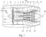
- the Figure 1 schematically shows a turbofan engine 100, which has a fan stage with a fan 10 as a low-pressure compressor, a medium-pressure compressor 20, a high-pressure compressor 30, a combustion chamber 40, a high-pressure turbine 50, a medium-pressure turbine 60 and a low-pressure turbine 70.
- the medium pressure compressor 20 and the high pressure compressor 30 each have a plurality of compressor stages, each comprising a rotor stage and a stator stage.
- the turbofan engine 100 of the Figure 1 furthermore has three separate shafts, a low-pressure shaft 81, which connects the low-pressure turbine 70 to the fan 10, a medium-pressure shaft 82, which connects the medium-pressure turbine 60 to the medium-pressure compressor 20, and a high-pressure shaft 83, which connects the high-pressure turbine 50 to the high-pressure compressor 30.
- this is only to be understood as an example.
- the turbofan engine has no medium pressure compressor and no medium pressure turbine, only a low pressure shaft and a high pressure shaft are present.
- the turbofan engine 100 has an engine nacelle 1, which comprises an inlet lip 14 and forms an engine inlet 11 on the inside, which supplies inflowing air to the fan 10.
- the fan 10 has a plurality of fan blades 101, which are connected to a fan disk 102.
- the annulus of the fan disk 102 forms the radially inner boundary of the flow path through the fan 10. Radially outside, the flow path is delimited by a fan housing 2.
- a nose cone 103 is arranged upstream of the fan disk 102.
- the turbofan engine 100 forms a secondary flow channel 4 and a primary flow channel 5.
- the primary flow duct 5 leads through the core engine (gas turbine), which comprises the medium-pressure compressor 20, the high-pressure compressor 30, the combustion chamber 40, the high-pressure turbine 50, the medium-pressure turbine 60 and the low-pressure turbine 70.
- the medium-pressure compressor 20 and the high-pressure compressor 30 are surrounded by a circumferential housing 29 that forms an annular space on the inside that delimits the primary flow channel 5 radially on the outside. Radially on the inside, the primary flow duct 5 is delimited by corresponding ring surfaces of the rotors and stators of the respective compressor stages or by the hub or elements of the corresponding drive shaft connected to the hub.
- a primary flow flows through the primary flow duct 5, which is also referred to as the main flow duct.
- the secondary flow duct 4 also referred to as a bypass duct or bypass duct, directs air sucked in by the fan 10 past the core engine during operation of the turbofan engine 100.
- the components described have a common axis of rotation or machine 90.
- the axis of rotation 90 defines an axial direction of the turbofan engine.
- a radial direction of the turbofan engine is perpendicular to the axial direction.
- the configuration of the turbine blades, in particular the turbine blades of the high-pressure turbine 50, is important in the context of the present invention. However, the principles of the present invention are also applicable to turbine blades of other turbine stages.
- the turbine blades considered in the context of the invention are part of a rotor blade arrangement which comprises a turbine disk and a turbine rotor blade ring with turbine rotor blades.
- the turbine blades are referred to as turbine blades in the context of this description.
- the turbine disk For fastening the turbine blades at an equidistant distance on the circumference of the turbine disk, the turbine disk has a plurality of blade root receptacles on its periphery, each of which serves to receive a blade root of a moving blade. It can be provided that the blade feet are designed as so-called "fir tree feet".
- the blade root receptacles are designed in a corresponding manner.
- the Turbine disk has channels which serve to provide cooling air for cooling the turbine blades.
- the Figure 2 shows an exemplary embodiment of a negative model of a turbine blade.
- the hollows of the turbine blade are shown in the negative model.
- These form a system 15 of cooling air channels, which serve to cool the turbine blade.
- the system 15 of cooling air ducts comprises two inlet cooling air ducts 16, 17, both of which extend in the blade root of the turbine blade.
- the input cooling air channels 16, 17 form a bulge 7 in which the cross-sectional area of the input cooling air channels 16, 17 has a maximum.
- the one input channel 16 extends as a cooling air channel 161 adjacent to the front edge of the turbine blade.
- the other input duct 17 forms a cooling air duct with three serpentine-like sections 171, 172, 173 in the direction of flow behind the bulge 7, which run essentially in the radial direction and are connected to one another by curved regions.
- the Figure 2 is only to be understood as an example.
- the exact shape and number of cooling air channels and the type of cooling are not important for the present invention.
- film cooling and / or cooling by convection can take place.
- Only the bulge 7 formed in the inlet cooling air channels 16, 17 is of importance for the present invention.
- the cooling air channels basically have any cross-sectional shape, for example circular, elliptical or rectangular.
- the Figures 3 and 4th show a turbine blade 200 that includes a system 15 of cooling air ducts corresponding to FIG Figure 2 having. This is in the Figures 3 and 4th indicated by a transparent representation of the turbine blade.
- the turbine blade 200 is in the Figure 3 in a view from the front, ie in a view in the axial direction shown on the front edge of the blade.
- the turbine blade 200 is in the Figure 4 shown in a side view of the print page.
- the turbine blade 200 comprises a blade root 21 and an airfoil 22.
- the blade root 21 is provided to be arranged in a blade root receptacle of a turbine blade. For example, it has a fir tree profile 23.
- the airfoil 22 includes a suction side 24, a pressure side 25, a front edge 26, a rear edge 27, a blade tip 28.
- the airfoil 22 projects into the primary flow channel of the turbofan engine.
- the circumferential direction ⁇ is perpendicular to x and r.
- the axial direction x can be identical to the machine axis of a gas turbine in which the invention is implemented, but can also deviate therefrom (for example if the rotor blades are inserted into the blade root receptacles at an angle to the machine axis).
- the input cooling air channels 16, 17 and the cooling air channels 161, 171, 172, 173 extend essentially in the radial direction.
- the in the Figure 2 shown and in the Figure 3 Recognizable bulge 7 extends in the direction of the pressure side 25 of the turbine blade 200.
- the Figure 5 shows an enlarged view in a perspective view obliquely from the front of the blade root 21, in which the inlet cooling air channels 16, 17 are formed.
- the illustration ends at a sectional area A, which forms a cross-sectional area of the blade root 21 perpendicular to the radial direction r.
- the shape of the one input cooling air duct 16 is schematically ( Figure 6 ) and on the other hand using an exemplary embodiment ( Figures 7-10 ) explained by way of example.
- the statements apply in a corresponding manner to the further input cooling air duct 17 in FIG Figures 3-5 , It is not imperative that both inlet cooling air ducts 16, 17 have a shape according to the invention.
- the turbine blade 200 does not necessarily have to have a plurality of inlet cooling air ducts 16, 17. In alternative configurations of the invention, only one input cooling air duct is provided, which is then designed as described below.
- the Figure 6 is a three-dimensional representation of an input cooling air duct 16 (hereinafter referred to as cooling air duct 16).
- the cooling air duct 16 comprises a first, widening section 3, in which the cross-sectional area of the cooling air channel 16 increases in the flow direction of the cooling medium from a cross-sectional area A1 at the beginning of the widening section 3 to a maximum A3.
- the first, widening section 3 is followed by a second, narrowing section 6, in which the cross-sectional area is reduced from the maximum cross-sectional area A3 to a cross-sectional area A2 at the end of the narrowing section 6.
- the wall of this subsection is formed towards the pressure side 25 by a wall contour 31 and towards the suction side 24 through a wall contour 32.
- the wall of this subsection is formed towards the pressure side 25 by a wall contour 61 and towards the suction side 24 through a wall contour 62.
- the changing cross sections of the cooling air duct 16 lead to a delay in the flow rate of the cooling medium in the widening section 3 and to an acceleration of the flow rate of the cooling medium in the tapering section 6.
- the cooling air duct 16 is further shaped in the sections 3, 6 under consideration such that the cooling medium in the second, narrowing subsection 6 is accelerated with a directional component in the direction of the suction side of the turbine blade. This acceleration of the cooling medium counteracts an acceleration of the cooling medium due to the Coriolis force. In this way, in a cross-sectional plane under consideration, the heat transfer is homogenized on all wall areas of the cooling air duct.
- the cooling air channel 16 forms the bulge 7 on the pressure side, the cooling medium being deflected in the first partial area 3 in the direction of the pressure side and in the second partial area 6 in the direction of the suction side.
- the exact shape is as follows.
- the cross-sectional area A1 is the cross-sectional area at the beginning of the first subarea 3. Starting from this, the cross-sectional area of the cooling air duct increases rotationally asymmetrically with respect to its center line in the direction of the pressure side.
- the geometric course of the cooling air duct 16 is described over its center line, which is the connecting line of all represents geometric centers (ie centroids) of the cross-sectional areas of the cooling air duct.
- a cross-sectional area of the cooling air duct 16 that is representative of the cooling air flow is defined such that the center line of the cooling air duct 16 always penetrates the plane of the cross-sectional area perpendicularly. In other words, the normal vector of such a cross-sectional area corresponds to the tangent vector to the center line in the geometric center (center of area) of the respective cross-sectional area.
- the cross-sectional expansion can be rotationally symmetrical or alternatively rotationally asymmetrical with respect to the center line of the cooling air duct.
- the rotationally asymmetrical channel widening which is initially accompanied by a routing of the cooling air channel 16 in the direction of the pressure side, leads to an increase in the structurally feasible deflection angle ⁇ in the second partial area 6.
- the degree of divergence of the expanding cooling air duct 16 should not exceed a maximum degree of divergence. Similar to an opening angle definition for diffusers, the maximum increase in the cross-sectional area of the cooling air duct 16 in the first subsection 3 is expediently related to the length of the flow path in the same, so that this ratio describes the degree of divergence in the first subsection 3. For the purposes of the present invention, this maximum ratio is defined as A 3rd - A 1 2nd s ⁇ 6 .
- the size s describes the length of the cooling air duct along its center line in the first subsection 3 and the sizes A1 and A3 already mentioned the cross-sectional areas of the cooling air duct 16 at the beginning and respectively at the end of the first subsection 3.
- the ratio is between 1.25 and 2.
- the cross-sectional area ratio A3 / A1 is in the range between 1 and 5, for example between 2 and 4.
- the cross-sectional area A3 at the transition between the first partial area 3 and the second partial area 6 represents the maximum cross-sectional area. Starting from this maximum, the cooling air duct 16 tapers in the second partial area 6.
- the convergence of the cooling air duct in the second partial area 6 is defined by the ratio A3 / A2. It is provided that this ratio is less than the ratio A3 / A1, in other words A1 is less than A2 and A2 is less than A3: A 1 ⁇ A 2nd ⁇ A 3rd .
- the shape of the convergence in the second partial region 6 is determined, inter alia, by the convergence or deflection angle ⁇ .
- This is the angle ⁇ is defined as the angle that lies between the two vectors A 3 A 1 and A 3 A 2 spans. Both vectors describe the direct connection line between the geometric centers (centroids) 310, 210 and 110 of the cross-sectional areas A3 and A2 or A3 and A1.
- the definition thus specifies the mean deflection angle of the cooling air duct over both subsections 3, 6, in the direction of the suction side.
- the deflection angle ⁇ is a maximum of 175 °. It is, for example, in the range between 110 ° and 170 °, in particular in the range between 140 ° and 170 °.
- cross-sectional area mentioned here is defined by a normal vector which corresponds to the tangent vector to the center line in the geometric center (center of area) of the cross-sectional area.
- the first, widening section 3 is shaped such that the vector A 1 A 3 or the center line of the cooling air duct in the first subsection 3, which is at least approximately the vector A 1 A 3 corresponds to, due to the bulge 7, which extends in the direction of the pressure side 25, has a directional component towards the cross-sectional area A3 in the direction of the pressure side 25 and does not run exactly radially.
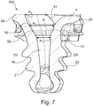
- the Figure 7 shows an example of an embodiment of a cooling air duct 16, which corresponds to the Figure 6 shaped and formed in the blade root 21 of a turbine blade 200.
- the Figures 8, 9 and 10 show cross sections perpendicular to the radial direction of the blade root 21 at the height of the cross section A2 ( Figure 8 ), of cross section A3 ( Figure 9 ) and cross section A1 ( Figure 10 ).
- the Figure 7 shows the first diverging section 3 with the wall contours 31, 32, the second converging wall section 6 with the wall contours 61, 62 and the three cross-sectional areas A1, A3, and A2.
- the bulge 7 extends in the direction of the pressure side 25.
- the cooling air duct 16 is approximately circular in the area of the cross-sectional area A1 (rotationally symmetrical with respect to the center line). Wall areas that extend in the direction of the pressure side or suction side are not provided. According to the Figure 9 the cooling air duct 16 is no longer circular in the area of the cross-sectional area A3 (but rotationally asymmetrical with respect to the center line). Rather, the wall areas 31, 32 designed as described lead according to FIG Figure 7 to a greater extent in the circumferential direction (between the pressure side and the suction side) than in the axial direction. The same applies according to the Figure 8 for the cooling air duct 16 in the area of the cross-sectional area A2, wherein the inclined wall area 62 can be seen in the top view shown from above.
Landscapes
- Engineering & Computer Science (AREA)
- Mechanical Engineering (AREA)
- General Engineering & Computer Science (AREA)
- Physics & Mathematics (AREA)
- Fluid Mechanics (AREA)
- Turbine Rotor Nozzle Sealing (AREA)
Claims (12)
- Aube de turbine (200) d'une couronne d'aubes mobiles de turbine, qui présente :- un côté d'aspiration (24),- un côté de pression (25), et- un canal d'air de refroidissement (16), par lequel un réfrigérant peut être transporté pour refroidir l'aube de turbine (200),- le canal d'air de refroidissement (16) présentant, dans au moins une portion, une allure telle que- sa surface en section transversale augmente, dans la direction d'écoulement du réfrigérant dans une première portion partielle s'élargissant (3), jusqu'à un maximum,- sa surface en section transversale diminue, dans une deuxième portion partielle se rétrécissant (6), derrière le maximum, et- le réfrigérant, dans la deuxième portion partielle se rétrécissant (6), soit accéléré avec une composante directionnelle dans la direction du côté d'aspiration (24) de l'aube de turbine (200),
caractérisée en ce que- le canal d'air de refroidissement (16) forme, dans la région du maximum, un renflement (7) dans la direction du côté de pression (25), le réfrigérant étant dévié dans la première portion partielle (3) dans la direction du côté de pression (25) et dans la deuxième portion partielle (6) dans la direction du côté d'aspiration (24),- l'axe médian du canal d'air de refroidissement (16) présentant, dans la première portion partielle (3), une composante directionnelle dans la direction du côté de pression (25) de l'aube de turbine, et- pour l'accélération du réfrigérant dans la deuxième portion partielle se rétrécissant (6), dans la direction du côté d'aspiration (24) de l'aube de turbine (100), l'axe médian du canal d'air de refroidissement (16) présentant, dans la deuxième portion partielle se rétrécissant (6), une composante directionnelle dans la direction du côté d'aspiration (24). - Aube de turbine selon la revendication 1, caractérisée en ce que le canal d'air de refroidissement (16) présente, au niveau du début de la portion partielle s'élargissant (3), une première surface en section transversale A1, à l'extrémité de la portion partielle se rétrécissant (6), une deuxième surface en section transversale A2, et au niveau du maximum de la surface en section transversale, une troisième surface en section transversale A3.
- Aube de turbine selon la revendication 2, caractérisée en ce que pour le rapport entre la première surface en section transversale A1 et la troisième surface en section transversale A3, on a : 1 < A3/A1 ≤ 5.
- Aube de turbine selon la revendication 2 ou 3, caractérisée en ce que pour le rapport entre la première surface en section transversale A1, la deuxième surface en section transversale A2 et la troisième surface en section transversale A3, on a :

- Aube de turbine selon l'une quelconque des revendications précédentes, caractérisée en ce que le canal d'air de refroidissement (16), dans la portion partielle s'élargissant (3), ne dépasse pas un degré maximal de divergence, le degré de divergence étant défini par la racine carrée de la croissance de la surface en section transversale (A3 - A1) par rapport à la longueur (s) du canal d'air de refroidissement le long de son axe médian, et le degré ainsi défini de divergence étant inférieur ou égal à 6, c'est-à-dire

- Aube de turbine selon la revendication 5, caractérisée en ce que le degré de divergence dans la portion partielle s'élargissant (3) du canal d'air de refroidissement (16) est compris entre 1,25 et 2, c'est-à-dire

- Aube de turbine selon l'une quelconque des revendications précédentes, caractérisée en ce que l'élargissement de section transversale du canal d'air de refroidissement (16) présente une asymétrie en rotation par rapport à son axe médian.
- Aube de turbine selon l'une quelconque des revendications précédentes lorsqu'elles se rapportent à la revendication 2, caractérisée en ce que le canal d'air de refroidissement (16) présente, dans la portion partielle se rétrécissant (6), un angle de déviation (δ) qui est inférieur à 175°, δ étant défini comme étant l'angle qui est formé entre les deux vecteurs
A3A1 etA3A2 , les deux vecteurs décrivant à chaque fois la ligne de liaison directe entre les centres géométriques (310, 210, 110) des surfaces en section transversale A3 et A2, respectivement A3 et A1. - Aube de turbine selon la revendication 8, caractérisée en ce que l'angle de déviation (δ) est compris entre 140° et 170°.
- Aube de turbine selon l'une quelconque des revendications précédentes, caractérisée en ce que l'aube de turbine (200) présente une emplanture d'aube (21), la première portion partielle s'élargissant (3) et la deuxième portion partielle se rétrécissant (6) étant réalisées dans une portion du canal d'air de refroidissement (16) qui est disposée dans l'emplanture d'aube (21).
- Aube de turbine selon l'une quelconque des revendications précédentes, caractérisée en ce que la surface en section transversale de la deuxième portion partielle se rétrécissant (6) diminue derrière le maximum de manière successive et sans saut.
- Aube de turbine selon l'une quelconque des revendications précédentes, caractérisée en ce que la divergence dans la première portion partielle (3) dans la direction du côté de pression (25) de l'aube est supérieure à la divergence dans la direction du côté d'aspiration (24) de l'aube.
Applications Claiming Priority (1)
| Application Number | Priority Date | Filing Date | Title |
|---|---|---|---|
| DE102017126105.2A DE102017126105A1 (de) | 2017-11-08 | 2017-11-08 | Turbinenschaufel eines Turbinen-Laufschaufelkranzes |
Publications (2)
| Publication Number | Publication Date |
|---|---|
| EP3483391A1 EP3483391A1 (fr) | 2019-05-15 |
| EP3483391B1 true EP3483391B1 (fr) | 2020-06-03 |
Family
ID=64267497
Family Applications (1)
| Application Number | Title | Priority Date | Filing Date |
|---|---|---|---|
| EP18204562.5A Active EP3483391B1 (fr) | 2017-11-08 | 2018-11-06 | Pale de turbine d'une couronne de pale de turbine |
Country Status (3)
| Country | Link |
|---|---|
| US (1) | US11008871B2 (fr) |
| EP (1) | EP3483391B1 (fr) |
| DE (1) | DE102017126105A1 (fr) |
Families Citing this family (1)
| Publication number | Priority date | Publication date | Assignee | Title |
|---|---|---|---|---|
| US10767492B2 (en) | 2018-12-18 | 2020-09-08 | General Electric Company | Turbine engine airfoil |
Family Cites Families (6)
| Publication number | Priority date | Publication date | Assignee | Title |
|---|---|---|---|---|
| US7220103B2 (en) * | 2004-10-18 | 2007-05-22 | United Technologies Corporation | Impingement cooling of large fillet of an airfoil |
| US7249933B2 (en) | 2005-01-10 | 2007-07-31 | General Electric Company | Funnel fillet turbine stage |
| US7467922B2 (en) * | 2005-07-25 | 2008-12-23 | Siemens Aktiengesellschaft | Cooled turbine blade or vane for a gas turbine, and use of a turbine blade or vane of this type |
| FR2943092B1 (fr) * | 2009-03-13 | 2011-04-15 | Snecma | Aube de turbine avec un trou de depoussierage en base de pale |
| US8157505B2 (en) * | 2009-05-12 | 2012-04-17 | Siemens Energy, Inc. | Turbine blade with single tip rail with a mid-positioned deflector portion |
| EP3241988A1 (fr) * | 2016-05-04 | 2017-11-08 | Siemens Aktiengesellschaft | Agencement de refroidissement d'une aube de turbine à gaz |
-
2017
- 2017-11-08 DE DE102017126105.2A patent/DE102017126105A1/de not_active Withdrawn
-
2018
- 2018-11-05 US US16/180,882 patent/US11008871B2/en active Active
- 2018-11-06 EP EP18204562.5A patent/EP3483391B1/fr active Active
Non-Patent Citations (1)
| Title |
|---|
| None * |
Also Published As
| Publication number | Publication date |
|---|---|
| US20190153874A1 (en) | 2019-05-23 |
| US11008871B2 (en) | 2021-05-18 |
| DE102017126105A1 (de) | 2019-05-09 |
| EP3483391A1 (fr) | 2019-05-15 |
Similar Documents
| Publication | Publication Date | Title |
|---|---|---|
| DE69423789T2 (de) | Stroemungsleiteinrichtung fuer den kompressorteil einer stroemungsmaschine | |
| DE3530769C2 (de) | Schaufel für ein Gasturbinentriebwerk | |
| DE69321621T2 (de) | Turbinenschaufel mit stegen in der austrittskaufe, die als diffusoren wirken | |
| EP3940200B1 (fr) | Roue à aubes d'une turbomachine | |
| DE112016003244T5 (de) | Abdeckung für Axialgebläseanordnung | |
| EP3428393B1 (fr) | Roue aubagée d'une turbomachine | |
| CH707459A2 (de) | Innenkühlungsaufbau einer Turbinenlaufschaufel. | |
| EP2226511A2 (fr) | Turbomachine de travail dotée d'une arrivée de fluide | |
| DE102015219556A1 (de) | Diffusor für Radialverdichter, Radialverdichter und Turbomaschine mit Radialverdichter | |
| DE102019200885A1 (de) | Leitgitter für eine Strömungsmaschine | |
| EP2538024A1 (fr) | Aube dans une turbomachine | |
| EP3032032B1 (fr) | Aubes directrices de sortie et turboréacteur à double flux avec des aubes directrices de sortie | |
| DE102018108940A1 (de) | Turbofantriebwerk für ein Luftfahrzeug | |
| DE102019110834A1 (de) | Zapfluftentnahmevorrichtung für ein Gasturbinentriebwerk | |
| CH701927B1 (de) | Statoranordnung, Kompressor und Gasturbinenmotor. | |
| DE102016124806A1 (de) | Turbinen-Laufschaufelanordnung für eine Gasturbine und Verfahren zum Bereitstellen von Dichtluft in einer Turbinen-Laufschaufelanordnung | |
| CH710576A2 (de) | Turbinenschaufel mit mehreren Kühlkanälen. | |
| DE102012104240B4 (de) | Hybridströmungs-Schaufeldesigns | |
| EP2913481B1 (fr) | Aubes en tandem d'une turbomachine | |
| DE102016124147B4 (de) | Innenkühlkonfigurationen in Turbinenrotorschaufeln | |
| EP3483391B1 (fr) | Pale de turbine d'une couronne de pale de turbine | |
| EP3492701A1 (fr) | Canal d'écoulement de turbomachine | |
| EP3327258A1 (fr) | Roue de guidage d'entrée pour une turbomachine | |
| EP4477839A2 (fr) | Procédé de détermination de la forme d'une aube désaccordée d'une roue porteuse d'une turbomachine | |
| DE102018130298A1 (de) | Baugruppe mit einem Ausgangsleitrad für ein Turbofantriebwerk und Turbofantriebwerk mit einer solchen Baugruppe |
Legal Events
| Date | Code | Title | Description |
|---|---|---|---|
| PUAI | Public reference made under article 153(3) epc to a published international application that has entered the european phase |
Free format text: ORIGINAL CODE: 0009012 |
|
| STAA | Information on the status of an ep patent application or granted ep patent |
Free format text: STATUS: THE APPLICATION HAS BEEN PUBLISHED |
|
| AK | Designated contracting states |
Kind code of ref document: A1 Designated state(s): AL AT BE BG CH CY CZ DE DK EE ES FI FR GB GR HR HU IE IS IT LI LT LU LV MC MK MT NL NO PL PT RO RS SE SI SK SM TR |
|
| AX | Request for extension of the european patent |
Extension state: BA ME |
|
| STAA | Information on the status of an ep patent application or granted ep patent |
Free format text: STATUS: REQUEST FOR EXAMINATION WAS MADE |
|
| 17P | Request for examination filed |
Effective date: 20191112 |
|
| RBV | Designated contracting states (corrected) |
Designated state(s): AL AT BE BG CH CY CZ DE DK EE ES FI FR GB GR HR HU IE IS IT LI LT LU LV MC MK MT NL NO PL PT RO RS SE SI SK SM TR |
|
| GRAP | Despatch of communication of intention to grant a patent |
Free format text: ORIGINAL CODE: EPIDOSNIGR1 |
|
| STAA | Information on the status of an ep patent application or granted ep patent |
Free format text: STATUS: GRANT OF PATENT IS INTENDED |
|
| RIC1 | Information provided on ipc code assigned before grant |
Ipc: F01D 5/18 20060101ALI20191129BHEP Ipc: F01D 5/14 20060101AFI20191129BHEP Ipc: F01D 5/08 20060101ALI20191129BHEP |
|
| INTG | Intention to grant announced |
Effective date: 20200103 |
|
| GRAS | Grant fee paid |
Free format text: ORIGINAL CODE: EPIDOSNIGR3 |
|
| GRAA | (expected) grant |
Free format text: ORIGINAL CODE: 0009210 |
|
| STAA | Information on the status of an ep patent application or granted ep patent |
Free format text: STATUS: THE PATENT HAS BEEN GRANTED |
|
| AK | Designated contracting states |
Kind code of ref document: B1 Designated state(s): AL AT BE BG CH CY CZ DE DK EE ES FI FR GB GR HR HU IE IS IT LI LT LU LV MC MK MT NL NO PL PT RO RS SE SI SK SM TR |
|
| REG | Reference to a national code |
Ref country code: GB Ref legal event code: FG4D Free format text: NOT ENGLISH |
|
| REG | Reference to a national code |
Ref country code: CH Ref legal event code: EP Ref country code: AT Ref legal event code: REF Ref document number: 1277210 Country of ref document: AT Kind code of ref document: T Effective date: 20200615 |
|
| REG | Reference to a national code |
Ref country code: DE Ref legal event code: R096 Ref document number: 502018001596 Country of ref document: DE |
|
| REG | Reference to a national code |
Ref country code: LT Ref legal event code: MG4D |
|
| PG25 | Lapsed in a contracting state [announced via postgrant information from national office to epo] |
Ref country code: FI Free format text: LAPSE BECAUSE OF FAILURE TO SUBMIT A TRANSLATION OF THE DESCRIPTION OR TO PAY THE FEE WITHIN THE PRESCRIBED TIME-LIMIT Effective date: 20200603 Ref country code: NO Free format text: LAPSE BECAUSE OF FAILURE TO SUBMIT A TRANSLATION OF THE DESCRIPTION OR TO PAY THE FEE WITHIN THE PRESCRIBED TIME-LIMIT Effective date: 20200903 Ref country code: GR Free format text: LAPSE BECAUSE OF FAILURE TO SUBMIT A TRANSLATION OF THE DESCRIPTION OR TO PAY THE FEE WITHIN THE PRESCRIBED TIME-LIMIT Effective date: 20200904 Ref country code: SE Free format text: LAPSE BECAUSE OF FAILURE TO SUBMIT A TRANSLATION OF THE DESCRIPTION OR TO PAY THE FEE WITHIN THE PRESCRIBED TIME-LIMIT Effective date: 20200603 Ref country code: LT Free format text: LAPSE BECAUSE OF FAILURE TO SUBMIT A TRANSLATION OF THE DESCRIPTION OR TO PAY THE FEE WITHIN THE PRESCRIBED TIME-LIMIT Effective date: 20200603 |
|
| REG | Reference to a national code |
Ref country code: NL Ref legal event code: MP Effective date: 20200603 |
|
| PG25 | Lapsed in a contracting state [announced via postgrant information from national office to epo] |
Ref country code: RS Free format text: LAPSE BECAUSE OF FAILURE TO SUBMIT A TRANSLATION OF THE DESCRIPTION OR TO PAY THE FEE WITHIN THE PRESCRIBED TIME-LIMIT Effective date: 20200603 Ref country code: BG Free format text: LAPSE BECAUSE OF FAILURE TO SUBMIT A TRANSLATION OF THE DESCRIPTION OR TO PAY THE FEE WITHIN THE PRESCRIBED TIME-LIMIT Effective date: 20200903 Ref country code: LV Free format text: LAPSE BECAUSE OF FAILURE TO SUBMIT A TRANSLATION OF THE DESCRIPTION OR TO PAY THE FEE WITHIN THE PRESCRIBED TIME-LIMIT Effective date: 20200603 Ref country code: HR Free format text: LAPSE BECAUSE OF FAILURE TO SUBMIT A TRANSLATION OF THE DESCRIPTION OR TO PAY THE FEE WITHIN THE PRESCRIBED TIME-LIMIT Effective date: 20200603 |
|
| PG25 | Lapsed in a contracting state [announced via postgrant information from national office to epo] |
Ref country code: NL Free format text: LAPSE BECAUSE OF FAILURE TO SUBMIT A TRANSLATION OF THE DESCRIPTION OR TO PAY THE FEE WITHIN THE PRESCRIBED TIME-LIMIT Effective date: 20200603 Ref country code: AL Free format text: LAPSE BECAUSE OF FAILURE TO SUBMIT A TRANSLATION OF THE DESCRIPTION OR TO PAY THE FEE WITHIN THE PRESCRIBED TIME-LIMIT Effective date: 20200603 |
|
| PG25 | Lapsed in a contracting state [announced via postgrant information from national office to epo] |
Ref country code: ES Free format text: LAPSE BECAUSE OF FAILURE TO SUBMIT A TRANSLATION OF THE DESCRIPTION OR TO PAY THE FEE WITHIN THE PRESCRIBED TIME-LIMIT Effective date: 20200603 Ref country code: CZ Free format text: LAPSE BECAUSE OF FAILURE TO SUBMIT A TRANSLATION OF THE DESCRIPTION OR TO PAY THE FEE WITHIN THE PRESCRIBED TIME-LIMIT Effective date: 20200603 Ref country code: SM Free format text: LAPSE BECAUSE OF FAILURE TO SUBMIT A TRANSLATION OF THE DESCRIPTION OR TO PAY THE FEE WITHIN THE PRESCRIBED TIME-LIMIT Effective date: 20200603 Ref country code: IT Free format text: LAPSE BECAUSE OF FAILURE TO SUBMIT A TRANSLATION OF THE DESCRIPTION OR TO PAY THE FEE WITHIN THE PRESCRIBED TIME-LIMIT Effective date: 20200603 Ref country code: EE Free format text: LAPSE BECAUSE OF FAILURE TO SUBMIT A TRANSLATION OF THE DESCRIPTION OR TO PAY THE FEE WITHIN THE PRESCRIBED TIME-LIMIT Effective date: 20200603 Ref country code: PT Free format text: LAPSE BECAUSE OF FAILURE TO SUBMIT A TRANSLATION OF THE DESCRIPTION OR TO PAY THE FEE WITHIN THE PRESCRIBED TIME-LIMIT Effective date: 20201006 Ref country code: RO Free format text: LAPSE BECAUSE OF FAILURE TO SUBMIT A TRANSLATION OF THE DESCRIPTION OR TO PAY THE FEE WITHIN THE PRESCRIBED TIME-LIMIT Effective date: 20200603 |
|
| PG25 | Lapsed in a contracting state [announced via postgrant information from national office to epo] |
Ref country code: SK Free format text: LAPSE BECAUSE OF FAILURE TO SUBMIT A TRANSLATION OF THE DESCRIPTION OR TO PAY THE FEE WITHIN THE PRESCRIBED TIME-LIMIT Effective date: 20200603 Ref country code: PL Free format text: LAPSE BECAUSE OF FAILURE TO SUBMIT A TRANSLATION OF THE DESCRIPTION OR TO PAY THE FEE WITHIN THE PRESCRIBED TIME-LIMIT Effective date: 20200603 Ref country code: IS Free format text: LAPSE BECAUSE OF FAILURE TO SUBMIT A TRANSLATION OF THE DESCRIPTION OR TO PAY THE FEE WITHIN THE PRESCRIBED TIME-LIMIT Effective date: 20201003 |
|
| REG | Reference to a national code |
Ref country code: DE Ref legal event code: R097 Ref document number: 502018001596 Country of ref document: DE |
|
| PLBE | No opposition filed within time limit |
Free format text: ORIGINAL CODE: 0009261 |
|
| STAA | Information on the status of an ep patent application or granted ep patent |
Free format text: STATUS: NO OPPOSITION FILED WITHIN TIME LIMIT |
|
| PG25 | Lapsed in a contracting state [announced via postgrant information from national office to epo] |
Ref country code: DK Free format text: LAPSE BECAUSE OF FAILURE TO SUBMIT A TRANSLATION OF THE DESCRIPTION OR TO PAY THE FEE WITHIN THE PRESCRIBED TIME-LIMIT Effective date: 20200603 |
|
| 26N | No opposition filed |
Effective date: 20210304 |
|
| PG25 | Lapsed in a contracting state [announced via postgrant information from national office to epo] |
Ref country code: SI Free format text: LAPSE BECAUSE OF FAILURE TO SUBMIT A TRANSLATION OF THE DESCRIPTION OR TO PAY THE FEE WITHIN THE PRESCRIBED TIME-LIMIT Effective date: 20200603 |
|
| PG25 | Lapsed in a contracting state [announced via postgrant information from national office to epo] |
Ref country code: MC Free format text: LAPSE BECAUSE OF FAILURE TO SUBMIT A TRANSLATION OF THE DESCRIPTION OR TO PAY THE FEE WITHIN THE PRESCRIBED TIME-LIMIT Effective date: 20200603 |
|
| PG25 | Lapsed in a contracting state [announced via postgrant information from national office to epo] |
Ref country code: LU Free format text: LAPSE BECAUSE OF NON-PAYMENT OF DUE FEES Effective date: 20201106 |
|
| REG | Reference to a national code |
Ref country code: BE Ref legal event code: MM Effective date: 20201130 |
|
| PG25 | Lapsed in a contracting state [announced via postgrant information from national office to epo] |
Ref country code: IE Free format text: LAPSE BECAUSE OF NON-PAYMENT OF DUE FEES Effective date: 20201106 |
|
| PG25 | Lapsed in a contracting state [announced via postgrant information from national office to epo] |
Ref country code: TR Free format text: LAPSE BECAUSE OF FAILURE TO SUBMIT A TRANSLATION OF THE DESCRIPTION OR TO PAY THE FEE WITHIN THE PRESCRIBED TIME-LIMIT Effective date: 20200603 Ref country code: MT Free format text: LAPSE BECAUSE OF FAILURE TO SUBMIT A TRANSLATION OF THE DESCRIPTION OR TO PAY THE FEE WITHIN THE PRESCRIBED TIME-LIMIT Effective date: 20200603 Ref country code: CY Free format text: LAPSE BECAUSE OF FAILURE TO SUBMIT A TRANSLATION OF THE DESCRIPTION OR TO PAY THE FEE WITHIN THE PRESCRIBED TIME-LIMIT Effective date: 20200603 |
|
| PG25 | Lapsed in a contracting state [announced via postgrant information from national office to epo] |
Ref country code: MK Free format text: LAPSE BECAUSE OF FAILURE TO SUBMIT A TRANSLATION OF THE DESCRIPTION OR TO PAY THE FEE WITHIN THE PRESCRIBED TIME-LIMIT Effective date: 20200603 |
|
| REG | Reference to a national code |
Ref country code: CH Ref legal event code: PL |
|
| PG25 | Lapsed in a contracting state [announced via postgrant information from national office to epo] |
Ref country code: BE Free format text: LAPSE BECAUSE OF NON-PAYMENT OF DUE FEES Effective date: 20201130 |
|
| PG25 | Lapsed in a contracting state [announced via postgrant information from national office to epo] |
Ref country code: LI Free format text: LAPSE BECAUSE OF NON-PAYMENT OF DUE FEES Effective date: 20211130 Ref country code: CH Free format text: LAPSE BECAUSE OF NON-PAYMENT OF DUE FEES Effective date: 20211130 |
|
| P01 | Opt-out of the competence of the unified patent court (upc) registered |
Effective date: 20230528 |
|
| GBPC | Gb: european patent ceased through non-payment of renewal fee |
Effective date: 20221106 |
|
| PG25 | Lapsed in a contracting state [announced via postgrant information from national office to epo] |
Ref country code: GB Free format text: LAPSE BECAUSE OF NON-PAYMENT OF DUE FEES Effective date: 20221106 |
|
| REG | Reference to a national code |
Ref country code: AT Ref legal event code: MM01 Ref document number: 1277210 Country of ref document: AT Kind code of ref document: T Effective date: 20231106 |
|
| PG25 | Lapsed in a contracting state [announced via postgrant information from national office to epo] |
Ref country code: AT Free format text: LAPSE BECAUSE OF NON-PAYMENT OF DUE FEES Effective date: 20231106 |
|
| PG25 | Lapsed in a contracting state [announced via postgrant information from national office to epo] |
Ref country code: AT Free format text: LAPSE BECAUSE OF NON-PAYMENT OF DUE FEES Effective date: 20231106 |
|
| PGFP | Annual fee paid to national office [announced via postgrant information from national office to epo] |
Ref country code: DE Payment date: 20251126 Year of fee payment: 8 |
|
| PGFP | Annual fee paid to national office [announced via postgrant information from national office to epo] |
Ref country code: FR Payment date: 20251124 Year of fee payment: 8 |
|
| PGFP | Annual fee paid to national office [announced via postgrant information from national office to epo] |
Ref country code: AT Payment date: 20260410 Year of fee payment: 5 |