EP4477839A2 - Procédé de détermination de la forme d'une aube désaccordée d'une roue porteuse d'une turbomachine - Google Patents
Procédé de détermination de la forme d'une aube désaccordée d'une roue porteuse d'une turbomachine Download PDFInfo
- Publication number
- EP4477839A2 EP4477839A2 EP24155912.9A EP24155912A EP4477839A2 EP 4477839 A2 EP4477839 A2 EP 4477839A2 EP 24155912 A EP24155912 A EP 24155912A EP 4477839 A2 EP4477839 A2 EP 4477839A2
- Authority
- EP
- European Patent Office
- Prior art keywords
- blade
- detuned
- nominal
- initially
- profile elements
- Prior art date
- Legal status (The legal status is an assumption and is not a legal conclusion. Google has not performed a legal analysis and makes no representation as to the accuracy of the status listed.)
- Pending
Links
Images





Classifications
-
- G—PHYSICS
- G01—MEASURING; TESTING
- G01B—MEASURING LENGTH, THICKNESS OR SIMILAR LINEAR DIMENSIONS; MEASURING ANGLES; MEASURING AREAS; MEASURING IRREGULARITIES OF SURFACES OR CONTOURS
- G01B21/00—Measuring arrangements or details thereof, where the measuring technique is not covered by the other groups of this subclass, unspecified or not relevant
- G01B21/20—Measuring arrangements or details thereof, where the measuring technique is not covered by the other groups of this subclass, unspecified or not relevant for measuring contours or curvatures, e.g. determining profile
-
- F—MECHANICAL ENGINEERING; LIGHTING; HEATING; WEAPONS; BLASTING
- F01—MACHINES OR ENGINES IN GENERAL; ENGINE PLANTS IN GENERAL; STEAM ENGINES
- F01D—NON-POSITIVE DISPLACEMENT MACHINES OR ENGINES, e.g. STEAM TURBINES
- F01D5/00—Blades; Blade-carrying members; Heating, heat-insulating, cooling or antivibration means on the blades or the members
- F01D5/12—Blades
- F01D5/14—Form or construction
- F01D5/141—Shape, i.e. outer, aerodynamic form
-
- F—MECHANICAL ENGINEERING; LIGHTING; HEATING; WEAPONS; BLASTING
- F05—INDEXING SCHEMES RELATING TO ENGINES OR PUMPS IN VARIOUS SUBCLASSES OF CLASSES F01-F04
- F05D—INDEXING SCHEME FOR ASPECTS RELATING TO NON-POSITIVE-DISPLACEMENT MACHINES OR ENGINES, GAS-TURBINES OR JET-PROPULSION PLANTS
- F05D2260/00—Function
- F05D2260/81—Modelling or simulation
-
- F—MECHANICAL ENGINEERING; LIGHTING; HEATING; WEAPONS; BLASTING
- F05—INDEXING SCHEMES RELATING TO ENGINES OR PUMPS IN VARIOUS SUBCLASSES OF CLASSES F01-F04
- F05D—INDEXING SCHEME FOR ASPECTS RELATING TO NON-POSITIVE-DISPLACEMENT MACHINES OR ENGINES, GAS-TURBINES OR JET-PROPULSION PLANTS
- F05D2260/00—Function
- F05D2260/82—Forecasts
- F05D2260/821—Parameter estimation or prediction
Definitions
- the invention relates to methods for determining the shape of a detuned blade of an impeller of a turbomachine and to blades manufactured according to these methods.
- the blade of an impeller straightens itself due to centrifugal force when the impeller is rotating.
- a change in the thickness of a blade to detune it not only changes the dynamic properties (vibration frequencies), but also the static properties (torsional stiffness and rotating mass) and the aerodynamic profiles.
- the change in the static properties means that the blade in the erected state (in the so-called "hot shape") undergoes a design change compared to the cold state of the blade (when the impeller is not rotating). Such a design change can have a negative impact on efficiency.
- the present invention is based on the object of specifying methods for determining the shape of a mistuned blade of an impeller of a turbomachine, wherein the desired shape avoids negative effects of the blade shape in the hot state, which are attributable to a change in the thickness of the blade in the cold state. Furthermore, a corresponding blade of an impeller is to be provided.
- the solution according to the invention is based on the idea of avoiding the consequences of a change in the thickness of a blade that arise when the blade is hot by shaping the blade when it is cold in such a way that the undesirable consequence does not even occur when it is hot. This is achieved by changing the parameter for the initially detuned blades when it is cold.
- the undesirable design that arises when the blade is straightened when it is hot is thus avoided to a certain extent by changing the design when it is cold, which is ultimately the opposite.
- the solution according to the invention thus minimizes the adverse effects on aerodynamic efficiency and noise when a rotating blade of a turbomachine is given a frequency detuning.
- the manner in which the profile elements are stacked on top of each other and/or the stagger angle in the cold state are corrected, as will be explained later.
- shape of a blade is to be interpreted broadly. In particular, this includes all parameters that influence the blade itself or its alignment on an impeller. These include, for example, the stagger angle, the blade camber angle, the incidence angle, the deviation angle, the blade entry angle, the blade exit angle, the pitch of the blade and the narrowest cross-section of the blade channel between two blades. If only one of these parameters is changed in one of the profile elements, there is a changed blade shape or a blade that is detuned compared to a nominal blade within the meaning of the present invention.
- a profile element is a profile section of small thickness through the blade. It is known that a blade profile is defined by radially threading individual profile elements.
- blade in the sense of the present invention primarily refers to the blade, i.e. the structure that interacts with a flowing medium.
- the blade can also have other components, for example a blade platform and a blade root, with which the blade is arranged in a rotor disk.
- the latter components can determine the natural frequency of the blade.
- a thickness change provided for in the invention took place on the blade.
- BLISK "Blade Integrated Disk”
- the blade essentially consists of the blade, which merges into a flow-limiting surface, for example a rotor hub, at at least one axial end.
- the blade considered according to the invention is the blade of a fan.
- the invention can also be used with other rotor blades, for example with blades of a compressor stage or a turbine stage of a gas turbine engine.
- the parameter of the initially detuned blade which is determined in the hot state
- a change in the stagger angle of the initially detuned blades in the cold state is achieved by changing the stagger angle in the cold state by the amount by which it differs from the stagger angle of the nominal blade in the hot state.
- the stagger angle of the detuned blade in the cold state is changed by an amount that is equal to the difference between the stagger angles of the detuned blade and the nominal blade in the hot state.
- a further embodiment of the invention provides that the parameter of the initially detuned blade, the value of which differs from the corresponding parameter value for the nominal blade in the hot state, is determined for all profile elements and a correction of this parameter is carried out for the initially detuned blade for all profile elements.
- the correction of the initially detuned blades according to the invention can be carried out for some or all of the profile elements.
- one design provides that the stagger angle is changed or corrected more as the span increases.
- the correction of the stagger angle can depend linearly on the span or radial height of the blade or can depend on the span or radial height in another way. This is related to the fact that a rotor blade typically straightens up and deforms less adjacent to the hub area in the hot state than the radially outer areas of the rotor blade.
- a further embodiment of the invention provides that, as a further parameter of the initially detuned blade, the center of gravity of the initially detuned blade is determined for at least some of the profile elements and compared with the center of gravity of the corresponding profile element of the nominal blade. If the centers of gravity differ, the center of gravity of the profile element of the initially detuned blade is shifted to the center of gravity of the nominal blade in the cold state by shifting the profile element.
- This aspect of the invention is based on the idea of restoring the center of gravity of a profile element that has changed due to the change in thickness or the associated addition or removal of mass in the sense that the center of gravity of the profile element is shifted back to the center of gravity that the profile element has in the nominal blade. This variant of the invention reduces a change in the shape of the blade in the hot state that is caused by the change in thickness.
- the center of gravity of a profile element is considered to be its center of mass. If the mass distribution within a profile element is homogeneous, the center of mass coincides with the area center of gravity of the profile element.
- the axial direction refers to the axial direction of a turbomachine such as a gas turbine engine in which the blade and the impeller on which the blade is arranged are arranged.
- the circumferential direction refers to the direction of rotation of the impeller on which the blade is arranged.
- a further embodiment provides that the centre of gravity of the profile elements of the initially detuned blade is compared with the centre of gravity of the corresponding profile element of the nominal blade for at least those profile elements for which the initially detuned blade realizes a change in thickness compared to the nominal blade, and for these profile elements the centre of gravity is set to the centre of gravity of the corresponding profile element of the nominal blade.
- This design is based on the fact that a correction of the center of gravity is only necessary for those profile elements for which a thickness change has occurred in the detuned blade.
- the initially detuned blade considered according to the invention differs from a nominal blade by thickness changes that have been carried out in at least some of the profile elements.
- the type and position of the thickness changes are not relevant for the present invention, however.
- any thickness changes can be made and any method can be used to determine suitable thickness changes in the overall profile.
- One embodiment variant provides that the thickness changes that lead to an initially detuned blade are made in sensitive areas of the blade in order to achieve the required frequency detuning in an efficient manner. For example, to determine efficient thickness changes, the difference between the distortion energy and the kinetic energy of an excited nominal blade is determined and the thickness of the nominal blade is increased or reduced depending on the determined difference between the distortion energy and the kinetic energy in a region under consideration.
- Another design provides that, with the initially detuned blade, a change in thickness only occurs on the pressure side of the blade.
- the suction side on the other hand, remains essentially unaffected by a change in thickness, so that the curvature of the suction side remains unchanged. This prevents negative effects on the rotor performance.
- One embodiment of the invention provides that the method according to the invention is carried out as a computer-implemented method, whereby the individual method steps are calculated and only after the final shape of the detuned blade is produced.
- the execution of such calculations is known to the person skilled in the art and is carried out, for example, using the finite element method.
- This aspect of the invention provides for restoring the center of gravity of a profile element, which has changed due to the change in thickness or the associated addition or removal of mass, in the sense that the center of gravity of the profile element is pushed back to the center of gravity that the profile element has with the nominal blade. This prevents an imbalance of the blade in the hot state caused by the change in thickness.
- the center of gravity of the profile element can be determined in the cold state.
- the method according to the invention can be carried out as a computer-implemented method, whereby the individual method steps are calculated and only after the final shape of the detuned blade has been determined is it manufactured.
- the present invention relates to a blade for an impeller of a turbomachine.
- the blade is characterized in that it is produced by carrying out the steps of the method according to claim 1 or the steps of the method according to claim 15 and then producing the blade according to the shape determined by the method steps.
- the blade is manufactured in a conventional manner, for example by casting, manufacturing from composite material, sintering, forging, milling or 3D printing.
- the blade A of the first group and the blades B of the at least one further group can be arranged, for example, in one of the following sequences: AB, 2A2B, 4A2B, 3A2B, 3A1B. If blades C of a third group are also present (which are, for example, detuned in a different way than the blades B), a sequence 2A1 B2C can be realized, for example, whereby the sequences mentioned are to be understood only as examples.
- the impeller can also have an even or an odd number of blades.
- the present invention relates to a gas turbine engine with an impeller according to the invention.
- the impeller according to the invention is, for example, a fan, an impeller in a compressor stage or an impeller in a turbine stage of a gas turbine engine.
- x indicates the axial direction
- r the radial direction
- ⁇ the angle in the circumferential direction.
- the axial direction is identical to the machine axis of a gas turbine engine in which the blade or impeller is arranged. Starting from the x-axis, the radial direction points radially outwards. Terms such as “in front”, “behind”, “front” and “rear” refer to the axial direction or the flow direction in the gas turbine engine. Terms such as “outer” or “inner” refer to the radial direction.
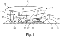
- Figure 1 represents a gas turbine engine 10 with a main axis of rotation 9.
- the engine 10 comprises an air inlet 12 and a fan 23 which generates two air streams: a core air stream A and a bypass air stream B.
- the gas turbine engine 10 comprises a core 11 which receives the core air stream A.
- the engine core 11 comprises, in axial flow order, a low-pressure compressor 14, a high-pressure compressor 15, a combustor 16, a high-pressure turbine 17, a low-pressure turbine 19 and a core thrust nozzle 20.
- An engine nacelle 21 surrounds the gas turbine engine 10 and defines a bypass duct 22 and a bypass thrust nozzle 18.
- the bypass air stream B flows through the bypass duct 22.
- the fan 23 is connected via a Shaft 26 and an epicycloid gear 30 are attached to the low-pressure turbine 19 and are driven by the latter.
- the core air stream A is accelerated and compressed by the low pressure compressor 14 and passed into the high pressure compressor 15 where further compression takes place.
- the compressed air discharged from the high pressure compressor 15 is passed into the combustor 16 where it is mixed with fuel and the mixture is combusted.
- the resulting hot combustion products then propagate through and drive the high pressure and low pressure turbines 17, 19 before being discharged through the nozzle 20 to provide some thrust.
- the high pressure turbine 17 drives the high pressure compressor 15 through a suitable connecting shaft 27.
- the fan 23 generally provides the majority of the thrust.
- the epicycloidal gear 30 is a reduction gear.
- low pressure turbine and “low pressure compressor” as used herein may be construed to mean the lowest pressure turbine stage and the lowest pressure compressor stage, respectively (i.e., not including the fan 23) and/or the turbine and compressor stages connected by the lowest speed connecting shaft 26 in the engine (i.e., not including the transmission output shaft that drives the fan 23).
- the "low pressure turbine” and “low pressure compressor” referred to herein may alternatively be known as the “intermediate pressure turbine” and “intermediate pressure compressor.”
- the fan 23 may be referred to as a first compression stage or lowest pressure compression stage.
- the geometry of the gas turbine engine 10 and components thereof is or are defined by a conventional axis system having an axial direction (aligned with the axis of rotation 9), a radial direction (in the direction from bottom to top in Figure 1 ) and a circumferential direction (perpendicular to the view in Figure 1 ).
- the axial, radial and circumferential directions are perpendicular to each other.
- the design of the blades of at least one impeller of a gas turbine engine is of importance, wherein the gas turbine engine is in accordance with Figure 1 or any other gas turbine engine, for example one that does not have a gearbox 30
- the impeller can be the fan, a compressor impeller or a turbine impeller.
- the compressor cascade is shown in the usual representation in meridional section and rolled out. It comprises a plurality of blades S, each of which has a leading edge S VK and a trailing edge S HK .
- the leading edges S VK lie on an imaginary line L 1
- the trailing edges S HK lie on an imaginary line L 2 .
- the lines L 1 and L 2 run parallel.
- the blades S also each comprise a suction side SS and a pressure side DS. Their maximum profile thickness is specified as d.
- the compressor cascade has a cascade pitch t and a profile chord s with a profile chord length s k .
- the profile chord s is the connecting line between the leading edge S VK and the trailing edge S HK of the profile.
- the blade staggering angle (hereinafter staggering angle) ⁇ s is formed between the profile chord s and the vertical on the line L 1 (where the vertical corresponds at least approximately to the direction defined by the machine axis).
- the staggering angle ⁇ s indicates the inclination of the blades S.
- the blades S have a skeleton line SL, which is also called the profile centerline. This is defined by the connecting line of the circle centers inscribed in the profile.
- the tangent to the skeleton line SL at the leading edge is designated T 1 .
- the tangent to the skeleton guideline SL at the trailing edge is designated T 2 .
- the angle at which the two tangents T 1 , T 2 intersect is the blade camber angle ⁇ .
- the inflow direction, in which gas flows towards the grid, is designated Z and the outflow direction, in which gas flows away from the grid, is designated D.
- the incidence angle ⁇ is defined as the angle between the tangent T 1 and the inflow direction Z.
- the deviation angle ⁇ 2 is defined as the angle between the tangent T 2 and the outflow direction A.
- a blade entry angle ⁇ 1 is defined as the angle between the tangent T 1 to the skeleton line SL and the perpendicular to the line L 1 .
- a blade exit angle ⁇ 2 is defined as the angle between the tangent T 2 to the skeleton line SL and the perpendicular to the line L 2 .
- the blade entry angle ⁇ 1 is also referred to as the blade entry angle or the inflow metal angle and the blade exit angle ⁇ 2 is also referred to as the blade exit angle or the outflow metal angle.
- the blade entry angle ⁇ 1 and the blade exit angle ⁇ 2 both change if the stagger angle ⁇ s is changed while the shape of the blades remains the same, since a change in the stagger angle ⁇ s in such a case changes the orientation of the tangents T 1 , T 2 due to the associated inclination adjustment of the blades.
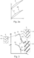
- a blade channel SK is formed between two adjacent blades S. This has a narrowest cross-section th. This is shown in the Figure 2a shown schematically and exemplarily.
- the Figure 3 illustrates the disadvantages that arise when the narrowest cross section th between the blades S of a blade row is outside the optimum.
- the Figure 3 shows the pressure ratio ⁇ p between the suction side and the pressure side of a blade and the efficiency ⁇ as a function of the mass flow q m .
- the point D1 indicates the optimum or the optimal design of the narrowest cross section of the blade channel SK, as it is given for nominal blades.
- the optimal design D1 corresponds to the partial representation 31.
- the compression shocks VS that occur run close to the leading edge of the adjacent blade S.
- the efficiency ⁇ is optimal when the shock is close to the leading edge.
- Point D2 corresponds to a design in which the narrowest cross section of the blade channel SK is smaller than in D1.
- Point D2 corresponds to partial representation 32.
- the mass flow q m through the blade channel SK is reduced and so is the efficiency ⁇ .
- the compression shocks VS' have migrated forwards or are expelled.
- Point D3 corresponds to a design in which the narrowest cross section of the blade channel SK is larger than in D1.
- the mass flow q m through the blade channel SK is increased, but the efficiency ⁇ is reduced.
- Point D3 corresponds to partial representation 33.
- the compression shocks VS" have migrated into the blade passage SK or are absorbed there.
- the aim is to always place the narrowest cross-section of the blade channel SK in the optimum D1.
- the narrowest cross-section of the blade channel SK depends on the stagger angle.
- the Figure 4 illustrates the consequences that can occur when a blade in the hot state, ie when the impeller to which it is attached is rotating, straightens up and changes its stagger angle. Such a change in the stagger angle can occur if the blade in question is not a nominal blade, but a detuned blade that has a reduced or increased thickness in at least one of its profile elements.
- the Figure 4 nominal blades 4 and initially detuned blades 5, which have a region with a thickness different from the nominal blades (in the Figure 4 not recognizable). If such initially detuned blades 5 straighten up and unwind in the hot state, the situation can arise that the stagger angle ⁇ changes.
- the Figure 4 shows the change in the stagger angle ⁇ for an initially detuned blade 5 and a concomitant change in the smallest cross section th ⁇ , th" in the two adjacent blade channels SK.
- the compression shocks VS ⁇ , VS" move axially forward in the blade channel with an increased smallest cross section th' compared to the compression shocks VS of the nominal blades 4 and are swallowed in the blade channel with a reduced smallest cross section th".
- the result is according to the Figure 3 in both cases a reduced efficiency.
- the Figure 4 This shows that changes in the aerodynamic profile (here the stagger angle) affect efficiency. In addition, the shifting of the shock waves can lead to additional noise generation.
- the invention therefore aims to modify the initially detuned blades 5 in the cold state, i.e. when the impeller to which it is attached is not rotating, in such a way that in the hot state it forms the same narrowest cross-section th and has the same stagger angle ⁇ as the nominal blades 4. In such a case, the initially detuned blade 5 assumes the shape 50 after its corresponding correction in the hot state.
- a profile element 41, 51 corresponds to a profile section of the blade 4, 5, whereby the term "profile element” makes it clear that it is not an infinitesimally thin section, but a section of finite thickness, so that the blade 4, 5 is threaded through a plurality of profile elements 41, 51.
- the change in the stagger angle and the narrowest cross-section of the blade channel shown can vary in intensity depending on the span or radial height of the blade, as can be seen from the Figure 10 will be explained later. It is important to note that the change in the stagger angle near the hub is smaller than towards the blade tip.
- the Figure 5 shows a nominal blade 4, whereby the blade 4 is, for example, a fan blade.
- the blade has, in a manner known per se, a leading edge 46, a trailing edge 42, a hub region 43 and a blade tip region 44. It comprises an airfoil 45 with a pressure side and a suction side.
- FIG. 1 A nominal blade 4 that has undergone a change in thickness for a targeted detuning is referred to as an initially detuned blade 5.
- a number of measures and methods are known for a targeted change in thickness.
- One variant of this provides that the difference between the distortion energy and the kinetic energy of an excited nominal blade 4 is determined and the thickness of the nominal blade 4 is increased or reduced depending on the determined difference between the distortion energy and the kinetic energy in a region under consideration.
- the thickness of the blade is increased or reduced in those regions in which the aforementioned difference is particularly large.
- area C of the Figure 5 an area of increased kinetic energy after an excitation of the blade.
- the area D of the Figure 5 indicates an area of increased distortion energy after an excitation of the blade. Thickness changes in these areas can lead in a particularly effective way to a targeted change in the natural frequency of the blade 4.
- This is basically in P. Gudmundson: "Tuning of Turbine Blades: A Theoretical Approach", Journal of Engineering for Power, ISSN 0022-0825, Vol. 105, No. 2, pp. 249-255, 1983 ,
- formula 30 of this publication describes how to determine the difference between the strain energy and the kinetic energy on the surface of a structure.
- a change in thickness is carried out in such a way that it only takes place on the pressure side of a blade. This is due to the fact that, in a fan in particular, the performance of the transonic section is mainly depends on the curvature of the suction side, so it is important to maintain this. On the other hand, this leads to a certain imbalance of the blade, which increases the deformation of the blade when hot.
- the Figure 6 shows, using a profile element 41, 51, a nominal blade 4 and a reduced-thickness and thus detuned blade 5, which are placed on top of each other, whereby the detuned blade 5 has a thickness reduced by ⁇ t on the pressure side DS.
- the profiles are identical.
- the detuned blade 5 is made from a nominal blade 4 according to the Figure 5 This was caused by a change in thickness in the area D of the Figure 5 has taken place.
- each profile element 41, 51 has a center of mass. With a homogeneous mass distribution, this corresponds to the center of gravity of the profile section. If now, according to the Figure 6 If the thickness of a nominal blade 4 is changed in certain areas, this leads to a changed center of mass.
- the Figure 7 The right image shows an enlarged view of the central area of the left image of the Figure 7 , which indicates the center of mass. Thus, the nominal blade 4 has a center of mass 72. After reducing the thickness ⁇ t, the initially detuned blade 5 has a modified center of mass 71, which is shifted relative to the center of mass 72.
- the thickness-reduced profile element is displaced in such a way that its center of mass is again on the center of mass 72, thus the center of mass 72 of the nominal blade 4 and the center of mass 71 of the initially detuned blade and then corrected with respect to its center of mass lie one above the other, wherein the initially detuned blade 5, which is corrected with respect to its center of mass, is referred to as blade 50a.
- Such a correction which is carried out by calculation before the blade is manufactured, can be made for all profile elements 51 for which a change in thickness has been made. It is pointed out that the determination of the Centers of mass 71, 72 and the shift of the center of mass of the initially detuned blade 5 to the corrected blade 50a can take place in the cold state of the blade.
- the Figure 8 shows the change in the stagger angle of the initially detuned blades 5 by a value ⁇ . This change occurs in the cold state of the initially detuned blade 5.
- the initially detuned blade 5, which is corrected with regard to the stagger angle, is referred to as blade 50b. It is pointed out that the change in the stagger angle is generated by rotating the profile element about an axis. The axis of rotation can pass through the center of mass of the profile element, although this is not necessarily the case.
- the Figure 9 shows a change in thickness according to the Figure 7 depending on the span Sp of the blade, which corresponds to the radial height of the blade.
- the left partial illustration 91 shows the nominal blade 4 according to the Figure 5 . This undergoes a change in thickness for targeted detuning.
- the corresponding change in thickness is shown in the partial representation 92, which shows the thickness t as a function of the span Sp.
- the profile of the blade thickness is shown for both the nominal blades 4 and the initially detuned blade 5. In certain radial areas, there is a change in thickness ⁇ t of the initially detuned blade 5 compared to the nominal blade 4.
- the initially detuned blade 5 has an increased thickness in a middle area and a reduced thickness in the upper area.
- Partial view 93 shows a shift of the center of mass MS as a function of the span Sp.
- the degree of the shift corresponds to the change in thickness according to partial view 92. This is due to the fact that in profile elements in which a large change in thickness has occurred, the corresponding profile element is corrected accordingly in its center of mass. In For profile elements that have not undergone any change in thickness, no correction of the centre of mass is required.
- the partial representation 94 shows the centers of mass MS of the nominal blade 4 and the initially detuned blade 50a and then corrected with respect to the center of mass as a function of the span Sp.
- the centers of mass of the nominal blade 4 and the corrected blade 50a are identical.
- the Figure 10 shows a corresponding sequence with regard to the correction of the stagger angle.
- Partial representation 101 shows the nominal blade 4, which undergoes a change in thickness for targeted detuning.
- Partial representation 102 shows the deformation d of the blade as a function of the span Sp. According to partial representation 103, this deformation corresponds to a change in the stagger angle that the detuned blade experiences in the hot state.
- the stagger angle ⁇ _h in the hot state is shown as a function of the span Sp.
- Partial representation 103 shows the detuned blade after a correction according to the Figure 9 , which is why the curves for the blades 4, 50a are compared. However, this is only optional. In principle, the stagger angle can also be corrected without correcting the center of mass. It can be seen that the change in the stagger angle ⁇ _h in the hot state increases with increasing span.
- the partial representation 104 shows the correction of the stagger angle ⁇ _c in the cold state of the detuned blade 50a,b.
- the stagger angle ⁇ _c is corrected over the entire span and thus for all profile elements.
- the partial representation 105 shows the stagger angle ⁇ _h in the hot state for both the nominal blade and the initially detuned and then twice corrected blade 50 (see also blade 50 of the Figure 4 ).
- the initially detuned blade 5 is corrected twice, namely firstly with regard to the center of mass of the individual profile elements and secondly with regard to the stagger angle of the individual profile elements.
- the desired result is achieved, namely that the stagger angle ⁇ _h of the nominal blade 4 and the finally corrected blade 50 do not differ.
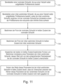
- the Figure 11 shows the main process steps for determining the shape of the detuned blade, whereby the initially detuned blade undergoes an additional change or correction.
- a nominal blade is first provided. This comprises a large number of radially threaded profile elements.
- an initially detuned blade is provided, which also comprises a large number of radially threaded profile elements.
- the initially detuned blade has a reduced or increased thickness compared to the nominal blade in at least one of the profile elements. For example, such a change in thickness is realized in certain areas on the pressure side of the blade.
- steps 113, 114 the shape of the nominal blade and the shape of the initially detuned blade in the hot state are now determined. This can be done, for example, using calculations according to the finite element method.
- the two shapes determined in the hot state are then compared with each other in step 115. If available, at least one parameter of the initially detuned blade is determined whose value differs from the corresponding parameter value of the nominal blade in the hot state. As explained, this parameter is, for example, the stagger angle of the blade.
- step 116 the value of this parameter is changed for the initially detuned blade in the cold state such that there is no longer a difference between the values of this parameter for the detuned blade and the nominal blade in the hot state.
- the stagger angle for the initially detuned blade in the cold state is changed such that in the hot state the shapes 4, 50 correspond to the Figure 4 and according to the partial representation 105 of the Figure 10 match.
- the Figure 11 The method described can be carried out iteratively in one embodiment. This is shown in the Figure 12 shown as an example. Then, in step 121, a nominal blade with a nominal design is provided, referred to as blade 1. In step 122, the deformation field d1 in the hot state of the blades is calculated for the nominal blade. Such a deformation field d1 is shown as an example in the Figure 13 The deformation field comprises different regions 40-n in which the nominal blade 4 is deformed differently in the hot state. For example, in a region 40_1 adjacent to the hub 43, it has essentially no deformation and the deformation increases in the adjoining regions 40-n towards the blade tip 44 and the blade trailing edge 42.
- step 123 the index i is now increased by the value 1.
- step 124 the initially detuned blade is provided, which has thickness changes compared to the nominal blade. This is referred to as blade 2. Blade 2 is also described in
- step 125 the deformation field d 2,i is calculated in the hot state. The deformation field differs from the deformation field d1 according to the Figure 13 the nominal blade, i.e. the initially detuned blade has a different shape when hot than the nominal blade.
- step 127 it is checked whether the determined difference is below a residual error ⁇ . Since the initially detuned blade has not yet been corrected, this will typically not be the case. Then, in step 128, the initially detuned blade is corrected with regard to the stagger angle difference ⁇ i , i.e. the stagger angle of the initially detuned blade is changed accordingly when cold. The described process is then carried out again in a further iteration step. The design of blade 2 is recalculated and the differential deformation and the stagger angle difference are determined again, according to steps 125, 126.
- step 127 It is then checked again in step 127 whether the difference determined is below the residual error ⁇ . If this is the case, the process according to step 129 is terminated, i.e. the final shape of the initially detuned blades is determined. If this is not the case, another iteration takes place, etc.
- the Figure 14 shows the procedure steps for determining the shape of a mistuned blade in the case that a correction of the centres of gravity according to the Figures 7 and 9 Such a correction can be made in addition to a correction of the stagger angle. Alternatively, only a correction of the center of gravity can be made.
- a nominal blade is first provided. This comprises a plurality of radially threaded profile elements.
- an initially detuned blade is also provided, which also comprises a plurality of radially threaded profile elements. The initially detuned blade has a reduced or increased thickness compared to the nominal blade in at least one of the profile elements.
- the center of gravity of the profile elements is determined at least for the profile elements with reduced or increased thickness of the initially detuned blade.
- the center of gravity of these profile elements is determined for the corresponding profile elements of the nominal blade.
- the centers of gravity are the profile elements of the initially detuned blade and the nominal blade are compared. If the centers of gravity differ, which is typically the case due to the change in thickness, the centers of gravity of the profile elements of the initially detuned blade are shifted to the centers of gravity of the corresponding profile elements of the nominal blade according to step 146. This is done in relation to the cold state of the initially detuned blade.
- the methods according to the invention make it possible to determine the shape of a detuned blade of an impeller of a turbomachine.
- the sequence of different blades in a blade ring can be determined using an optimization program and is not limited to the classic AB pattern.
- Examples of more complex sequences are AB, 2A2B, 4A2B, 3A2B, 3A1B and 2A1B2C, where, for example, blades A of a first group are nominal blades, blades B of a second group are detuned blades, and blades C of a third group are also detuned blades, but are detuned in a different way than blades B.
Landscapes
- Physics & Mathematics (AREA)
- General Physics & Mathematics (AREA)
- Engineering & Computer Science (AREA)
- Fluid Mechanics (AREA)
- Mechanical Engineering (AREA)
- General Engineering & Computer Science (AREA)
- Structures Of Non-Positive Displacement Pumps (AREA)
Applications Claiming Priority (1)
| Application Number | Priority Date | Filing Date | Title |
|---|---|---|---|
| DE102023102798.0A DE102023102798A1 (de) | 2023-02-06 | 2023-02-06 | Verfahren zur Festlegung der Form einer verstimmten Schaufel eines Laufrads einer Strömungsmaschine |
Publications (2)
| Publication Number | Publication Date |
|---|---|
| EP4477839A2 true EP4477839A2 (fr) | 2024-12-18 |
| EP4477839A3 EP4477839A3 (fr) | 2025-03-26 |
Family
ID=89853295
Family Applications (1)
| Application Number | Title | Priority Date | Filing Date |
|---|---|---|---|
| EP24155912.9A Pending EP4477839A3 (fr) | 2023-02-06 | 2024-02-06 | Procédé de détermination de la forme d'une aube désaccordée d'une roue porteuse d'une turbomachine |
Country Status (3)
| Country | Link |
|---|---|
| US (1) | US20240263942A1 (fr) |
| EP (1) | EP4477839A3 (fr) |
| DE (1) | DE102023102798A1 (fr) |
Families Citing this family (1)
| Publication number | Priority date | Publication date | Assignee | Title |
|---|---|---|---|---|
| US12215597B1 (en) | 2024-01-26 | 2025-02-04 | Pratt & Whitney Canada Corp. | Gas turbine engine rotor blade geometry and method for selecting same |
Family Cites Families (8)
| Publication number | Priority date | Publication date | Assignee | Title |
|---|---|---|---|---|
| US20060073022A1 (en) * | 2004-10-05 | 2006-04-06 | Gentile David P | Frequency tailored thickness blade for a turbomachine wheel |
| EP1710551A1 (fr) * | 2005-03-18 | 2006-10-11 | Siemens Aktiengesellschaft | Procédé de mesure des caractéristiques des vibrations d'une aube d'essai pour turbine |
| US9097125B2 (en) * | 2012-08-17 | 2015-08-04 | Mapna Group | Intentionally frequency mistuned turbine blades |
| EP2959108B1 (fr) * | 2013-02-21 | 2021-04-21 | Raytheon Technologies Corporation | Turbine à gaz ayant un étage désaccordé |
| DE102014204725A1 (de) * | 2014-03-14 | 2015-09-17 | MTU Aero Engines AG | Verfahren zum Auslegen einer Turbine |
| CN108710746A (zh) * | 2018-02-08 | 2018-10-26 | 哈尔滨广瀚燃气轮机有限公司 | 虑及舰船燃机压气机动叶片预变形影响的反扭设计方法 |
| US10876409B2 (en) * | 2018-11-07 | 2020-12-29 | Honeywell International Inc. | Mistuned rotors and methods for manufacture |
| CN111368373B (zh) * | 2020-03-01 | 2022-06-03 | 南京航空航天大学 | 一种冷态叶型与热态叶型的迭代分析方法 |
-
2023
- 2023-02-06 DE DE102023102798.0A patent/DE102023102798A1/de active Pending
-
2024
- 2024-01-26 US US18/424,181 patent/US20240263942A1/en active Pending
- 2024-02-06 EP EP24155912.9A patent/EP4477839A3/fr active Pending
Non-Patent Citations (1)
| Title |
|---|
| P. GUDMUNDSON: "Tuning of Turbine Blades: A Theoretical Approach", JOURNAL OF ENGINEERING FOR POWER, vol. 105, no. 2, 1983, pages 249 - 255, ISSN: 0022-0825 |
Also Published As
| Publication number | Publication date |
|---|---|
| US20240263942A1 (en) | 2024-08-08 |
| DE102023102798A1 (de) | 2024-08-08 |
| EP4477839A3 (fr) | 2025-03-26 |
Similar Documents
| Publication | Publication Date | Title |
|---|---|---|
| EP3611387B1 (fr) | Roue à aubes d'une turbomachine | |
| EP3715586B1 (fr) | Pale d'aube de rotor d'une turbomachine | |
| DE602004006323T2 (de) | Verfahren zur Herstellung einer Turbine mit Turbinenschaufeln unterschiedlicher Resonanzfrequenzen samt einer solchen Turbine | |
| DE69515624T2 (de) | Compressorgehäuse mit Rezirkulationskanälen | |
| EP3999716B1 (fr) | Aube de rotor pour une turbomachine, module de turbine associé et utilisation des mêmes | |
| EP3428393B1 (fr) | Roue aubagée d'une turbomachine | |
| DE102019200885A1 (de) | Leitgitter für eine Strömungsmaschine | |
| EP3428434A1 (fr) | Turboréacteur | |
| DE102020131807A1 (de) | Gasturbinentriebwerksbetriebsmodus | |
| DE102019117038A1 (de) | Getriebe und Gasturbinentriebwerk | |
| EP4477839A2 (fr) | Procédé de détermination de la forme d'une aube désaccordée d'une roue porteuse d'une turbomachine | |
| EP2846000A2 (fr) | Roue statorique d'une turbine à gaz | |
| EP3530880A1 (fr) | Pale d'aube directrice avec section inclinée, segment d'aubes directrices, module, turbomachine et procédé de conception d'un module associés | |
| EP3599349A1 (fr) | Module structural avec aubes à calage variable inclinées pour un compresseur d'une turbomachine | |
| EP1723339A1 (fr) | Compresseur d'une turbine a gaz ainsi que turbine a gaz | |
| DE102020131804A1 (de) | Hochleistungsumlaufgetriebe und dessen betrieb | |
| WO2010063518A1 (fr) | Configuration géométrique des aubes de la roue d'un turbocompresseur | |
| DE102023102797A1 (de) | Verfahren zur Änderung der Eigenfrequenz einer Schaufel eines Schaufelrads einer Strömungsmaschine | |
| DE102018130298A1 (de) | Baugruppe mit einem Ausgangsleitrad für ein Turbofantriebwerk und Turbofantriebwerk mit einer solchen Baugruppe | |
| DE102019106999A1 (de) | Stirnradgetriebe und Planetengetriebe mit einem derartigen Stirnradgetriebe | |
| EP3483391B1 (fr) | Pale de turbine d'une couronne de pale de turbine | |
| DE102021122450A1 (de) | Planetengetriebe | |
| EP3670838B1 (fr) | Pale d'aube mobile pour une turbomachine | |
| DE102020122418A1 (de) | Planetengetriebe | |
| DE102020122678A1 (de) | Planetengetriebe |
Legal Events
| Date | Code | Title | Description |
|---|---|---|---|
| PUAI | Public reference made under article 153(3) epc to a published international application that has entered the european phase |
Free format text: ORIGINAL CODE: 0009012 |
|
| STAA | Information on the status of an ep patent application or granted ep patent |
Free format text: STATUS: THE APPLICATION HAS BEEN PUBLISHED |
|
| AK | Designated contracting states |
Kind code of ref document: A2 Designated state(s): AL AT BE BG CH CY CZ DE DK EE ES FI FR GB GR HR HU IE IS IT LI LT LU LV MC ME MK MT NL NO PL PT RO RS SE SI SK SM TR |
|
| PUAL | Search report despatched |
Free format text: ORIGINAL CODE: 0009013 |
|
| AK | Designated contracting states |
Kind code of ref document: A3 Designated state(s): AL AT BE BG CH CY CZ DE DK EE ES FI FR GB GR HR HU IE IS IT LI LT LU LV MC ME MK MT NL NO PL PT RO RS SE SI SK SM TR |
|
| RIC1 | Information provided on ipc code assigned before grant |
Ipc: F01D 5/14 20060101AFI20250217BHEP |
|
| STAA | Information on the status of an ep patent application or granted ep patent |
Free format text: STATUS: REQUEST FOR EXAMINATION WAS MADE |
|
| 17P | Request for examination filed |
Effective date: 20250722 |