EP3483581A1 - Methode et dispositif permettant de surveiller le jeu de palier de roulements a rouleaux - Google Patents
Methode et dispositif permettant de surveiller le jeu de palier de roulements a rouleaux Download PDFInfo
- Publication number
- EP3483581A1 EP3483581A1 EP18204784.5A EP18204784A EP3483581A1 EP 3483581 A1 EP3483581 A1 EP 3483581A1 EP 18204784 A EP18204784 A EP 18204784A EP 3483581 A1 EP3483581 A1 EP 3483581A1
- Authority
- EP
- European Patent Office
- Prior art keywords
- distance
- load
- bearing
- measurement
- measurements
- Prior art date
- Legal status (The legal status is an assumption and is not a legal conclusion. Google has not performed a legal analysis and makes no representation as to the accuracy of the status listed.)
- Granted
Links
Images

Classifications
-
- G—PHYSICS
- G01—MEASURING; TESTING
- G01M—TESTING STATIC OR DYNAMIC BALANCE OF MACHINES OR STRUCTURES; TESTING OF STRUCTURES OR APPARATUS, NOT OTHERWISE PROVIDED FOR
- G01M13/00—Testing of machine parts
- G01M13/04—Bearings
Definitions
- the invention relates to a device and a method for condition monitoring of the bearing clearance of a rolling bearing, in particular the bearing clearance of a large warehouse, especially a wind turbine and there particularly a main bearing.
- rolling bearing unit is meant in particular a single bearing with conversion parts (for example, moment bearing) or a shaft system consisting of shaft and housing and any rolling bearing number.
- the bearings to be monitored are generally rotary bearings, ie bearings which rotate in rotation around an axis of rotation (and not only pivot about an axis of rotation over a limited angular range).
- the bearing to be monitored is a bearing of a wind turbine, for example the so-called main bearing, via which a rotor is mounted, are mounted on the rotor blades.
- the focus is on the simplest possible but at the same time precise detection of the bearing clearance affecting damage such as wear of the raceways or rolling elements, wear in the bearing seat or improper setting or loosening of biasing or fixing.
- the bearing clearance is a decisive factor for the function of a storage system. If the bearing clearance increases (if positive) or if the bearing preload decreases due to the mentioned mechanisms, this leads to consequential damage in the medium or long term of the storage system until failure. However, if an impermissible change of bearing play is detected in time, appropriate measures can be taken to avoid consequential damage.
- DE 10 2010 035 264 A1 describes a device for adjusting an axial clearance of a bearing by means of piezo actuators.
- the aim of the device is the compensation of operating game changes due to temperature influences.
- the axial distance to the bearing inner ring is measured by means of a sensor attached to the housing. If the distance changes, this is corrected by the piezo elements until the output state is restored.
- monitoring of wear, set or release is not possible with this method. This is because, for example, wear on the bearing with the adjustment leads to an increase in distance and wear on the opposite bearing to a reduction in distance. The effects can cancel each other out.
- the measurement of significant temperature effects from normal operation is superimposed. Such a device is therefore not suitable for condition monitoring of a bearing clearance, but only to compensate for thermal expansion.
- EP 2 801 729 A2 offers a solution for this.
- This is also closed by a measurement of the distance to the bearing preload, but here are provided radial and axial distance measurements.
- additional temperature distribution measurements on the bearing it is possible to unambiguously deduce the existing bearing preload and, in addition, differentiate between temperature and the influence of wear.
- this method of measurement requires a large number of sensors and complex preliminary calculations to determine the correlations.
- bearings have manufacturing deviations. These may be plan and concentricity errors, evenness and roundness deviations or surface defects. If the distance during operation between a rotating and a stationary part is measured, this is expressed in a periodically varying distance signal, whereby the change in the distance due to production deviations can significantly exceed the change underlying the measurement target. If this is not taken into account in the evaluation, this can lead to the greatest variability in the measurement result and put it into question.
- the present invention is based on the object, with little measurement and calculation effort to enable condition monitoring for rolling bearing systems and yet reliably detect wear, setting and release. there So the goal is to monitor the bearing clearance after installation long term and not to determine or correct the operating clearance depending on the temperature distribution in the storage.
- the distance delta on changes in the bearing clearance closed.
- the distances on the basis of the change in particular in the case of an increase or decrease in the distance delta by a predetermined value (absolute and / or percentage)
- a predetermined value absolute and / or percentage
- an inadmissible change is concluded and appropriate measures are taken, such as the recommendation for readjustment of the bearing clearance or the recommendation for a stock exchange.
- a prediction for the further (residual) running time of the bearing, if necessary, up to a required revision, etc. is made (condition monitoring).
- At least two individual measurements at different load states are preferably initially carried out in the first measurement series and at least two distance values (a distance value per load state) are obtained.
- two absolute values are detected (measured) and set in relation to each other to obtain the distance difference.
- the detection and determination of the distance difference is performed by a relative measurement, i. only the change in distance is detected without measuring an absolute value for the two distance values.
- at least two individual measurements are carried out at the same or at least comparable load conditions as in the first measurement series and again at least two in the second measurement series Distance values recorded.
- the distance is continuously measured over a certain period of time (eg several seconds to minutes) and an average value is formed as a distance value from the plurality of measured values.
- a certain period of time eg several seconds to minutes
- an average value is formed as a distance value from the plurality of measured values.
- the distance delta is then used, for example, the distance of the average values in the various load conditions.
- the method takes advantage of the variable load conditions present in a majority of applications, which, however, are a problem in the approaches previously described in the prior art.
- this results in different load-dependent distances between the bearing rings, their conversion parts (such as bearing seat, a clamping ring for clamping the bearing, etc.) and / or shaft and housing.
- the distance changes depending on the load condition due to elastic deformation of the components.
- Under load condition a combination of certain forces, moments, temperatures, speed, etc. is understood to be a discrete time, wherein a load condition may also be a no-load condition.
- the load state changes between two levels, for example two different temperature levels or two different wind loads. So it can be determined a relative change in distance between the two load conditions. As long as the bearing clearance remains constant, the same load state change results in the same distance delta. Occurs a bearing game affecting damage (bearing clearance increases or bias decreases) this always leads to an increase in the distance delta with the same load state change. By monitoring the delta (trend formation) so a change in the bearing clearance is detected. With this procedure, it is not absolutely necessary to know the exact load conditions or the existing bearing clearance. It is assumed that during commissioning there is a suitable bearing preload and the load conditions repeat in the same way over time. This is the case in most applications.
- the game change is preferably also concluded by a prior calculation and / or by using a correlation stored in an evaluation unit.
- the loads may be radial loads, axial loads or moments, which thus act on the bearing in the radial direction or in the axial direction or as tilting.
- a distance between the housing and the shaft is detected.
- the radial load is an alternating load, i. If the direction of the load (load direction reversal) changes between two load conditions, the measurement makes the game easily determinable and a game increase (increasing distance delta with time) is easy to detect.
- the system also works when there is a swelling load. By swelling load is meant that the amount of load changes, but the direction of the load remains almost the same.
- a change between two predefined load states is detected, for example the change between two rotational speed levels, between two temperature levels or between two defined wind load conditions.
- the detection of the load conditions for example, with suitable sensors and / or is obtained from a plant control. If in each case the defined load state is present at which the respective measurement series is to take place, then the distance is detected. Between the measurements of the distance in the at least two defined load states is typically a certain period of seconds, minutes, hours, or even days, since the change between the two load conditions requires a certain amount of time. The period depends in particular on the type of load change. For example, Wind load-related stochastic load changes in very short periods of time in the range of a few seconds.
- the period is in the range of several tens of seconds (for example, to a maximum of ⁇ 1 min, ⁇ 5 min, or ⁇ 10 min).
- load changes e.g. as a result of starting up the system (cold - warm) the period is e.g. in the range of several tens of minutes to one hour or even up to several hours, e.g. up to 6 or even up to 10 hours.
- measurements are preferably carried out over a sufficiently long period of time, so that within this Period at least one change and thus a distance delta is detected. This period is for example hours, days or even weeks. By contrast, the individual measurement of the distance as such takes only a few seconds, for example a few minutes (1-3 min).
- the different load conditions are deliberately generated, i. by controlled intervention, e.g. set in the plant control. This is, for example, the change when the system starts up from a cold state to a warm operating state.
- a particularly complex example is the main storage of a wind turbine.
- a majority of the relevant load changes result from stochastic variable wind loads, i. Over a short period of time there is a random load-time behavior. For a short period of time, a period of typically several seconds, e.g. 5 to 20 seconds to a few minutes (1-10 minutes) understood. However, this random short-term load-time behavior is repeated over a long period, at least in a similar manner. For example, at a constant average wind speed, stochastic variations, ie fluctuations, occur. Experience shows that these fluctuations are the same or very similar in a statistical analysis. These load fluctuations are accompanied by different distances.
- a particular periodically repeating load-time behavior of the distances is detected. So it is almost a continuous course of the distances over the measurement period recorded. This course is evaluated with regard to the differences of the distances. The differences are there due to the (stochastic) variable loads.
- Such a series of measurements will be carried out at a later time than the second series of measurements as part of condition monitoring.
- the two measurement series are evaluated on the basis of the changes in the difference between the individual distance values of the respective measurement series.
- the two measurement series are preferably carried out at a same base load, ie an equal base load state, within which the stochastic deviations occur.
- this base load condition is defined by a constant average load (e.g., wind speed (wind load)).
- the base load condition is, for example, an equal average load (wind speed) over the time period for performing the series of measurements and preferably also with an equal or similar statistical variation (standard deviation or variance) of the mean load (wind speed) in the measurement period.
- the invention thus makes use of the stochastic changes, since the goal is a long-term monitoring of the bearing clearance. So there are regular series of measurements over a discrete time period (several seconds to several minutes). So a series of measurements will be made. Within such a series of measurements, stochastic changes of the load state and thus a stochastic variation of the distance signal occur. So it can be e.g. a difference between maximum and minimum within such a series of measurements (ie when a single load condition is present) is determined and evaluated with regard to a change of the position play.
- the distance sensor For the monitoring of the bearing clearance is basically a distance sensor sufficient, which is positioned as possible at a point where, depending on the design of the bearing and the load conditions of the application, the largest deformations or shifts between rotating and stationary parts occur. For this, the distance measurement does not necessarily have to be done in direct storage environment. Often, the effect even increases by leverage at some distance to the camp. However, care must be taken in positioning that other deformation effects due to e.g. other machine elements influence the result inadmissible. Furthermore, an accessibility of the sensor is advantageous in order to be able to replace it if necessary. If this is not feasible, several sensors can be placed next to each other for redundancy reasons.
- the manufacturing deviations are detected as part of a reference measurement and taken into account in the later measurement of the distance values.
- the bearing unit is rotated (at least one or several revolutions) whereby the angular position and the associated distance are detected and permanently stored in an evaluation unit.
- the reference measurement is preferably carried out in a no-load condition. At least during the reference measurement it is ensured that the load condition of the bearing unit does not change during the reference measurement.
- the distance change due to manufacturing deviations is then preferably subtracted from the measurement result.
- the values of the reference measurement are preferably brought into agreement with the operating measurement in terms of position or time. This is achieved, for example, by additional angular position detection, i. the values of the distance are detected at defined angles of rotation and only distance values which were detected at the same angles of rotation are compared with one another.
- At least one mark in a measuring surface against which the distance sensor measures is provided.
- a label may be e.g. to act a depression or an increase.
- the reference measurement is stretched or compressed to compensate for differences in speed.
- the rashes are above the level of the expected distances in operation. ie the depression or elevation is greater (for example at least by a factor of 1.5 or 2) a maximum expected change in the distance to be measured.
- three or more distance sensors are used, and it is further advantageous to distribute them at equal angular intervals over the circumference.
- the individual distance deltas (differences between the load states) of the individual distance sensors are then preferably used in each case.
- the simultaneous average value of the plurality of distance sensors and the distance delta of the mean value in a respective measurement series is preferably additionally detected.
- a simultaneous average value is understood to mean that the plurality of distance sensors detect the distance values at the same time (but precisely at different (angular) positions and average these distance values.) The sum of the measured individual distances (at a discrete point in time) of the plurality of sensors is determined by the Sensor number divided.
- the current speed can also be calculated from the distance signal. Preferably, this is also calculated.
- a particularly advantageous method for detecting the proportion of manufacturing deviations in the distance signal is to perform a phase shift of the measurement signals of the individual distance sensors.
- the individual measurement signals are (temporally) shifted according to their angular position, ie the angular position of the associated distance sensor, so that they lie congruently one above the other. That the individual measured values (distance values) or sensor signals are shifted in time so that they lie one above the other.
- the measured values are superimposed with respect to the same measuring angular position and can be averaged.
- the mean value is used as the distance value.
- the measurement is preferably evaluated over several revolutions and averaged. This can in turn be subtracted from the individual signals. As a result, the fluctuation of the distance signals decreases significantly and the change in distance due to the load condition can be extracted.
- a compensation of the change in distance due to circular and axial deviations is particularly advantageous when statistical characteristics for the determination of the distance delta such.
- the standard deviation of the distance variation during a series of measurements in a load condition should be determined. Otherwise, possibly the distance variation due to the manufacturing tolerances would be so dominant that the increase of the distance delta would be lost due to changes in the bearing clearance in the evaluation.
- the roundness and / or runout behavior is performed by a further reference measurement under a defined load condition and in particular compared with the earlier reference measurement.
- the distance values due to manufacturing deviations are further provided in a preferred development to eliminate changes in the distance values due to manufacturing deviations by forming a moving average value in order to (exactly) determine the present distance value based on the current load condition and the distance delta to determine other load conditions.
- the periodic character of the distance signal is utilized. Since the speed can be determined from the signal as described above, it is possible to define the range for the moving average as n times a rotor revolution, where n is greater than or equal to 1 and preferably equal to 2 and maximum 10. This makes it possible to completely eliminate the concentricity and concentricity in the measurement. This is because the mean value of the concentricity and concentricity curve is constant over one rotor revolution or its multiples.
- the relevant operating parameters are preferably recorded and the measurement results of the distance delta classified accordingly.
- the temperature of the storage unit plays an important role here. Therefore, it is advantageous to already integrate a temperature sensor in the distance sensor. This makes sense, in particular, if a measuring method is selected where the distance sensor already exhibits a temperature drift (eg inductive distance sensor). The temperature reading can then be used to classify the distance deltas.
- an evaluation unit When talking about an evaluation unit, this does not necessarily mean that it is a separate unit.
- the hardware or the evaluation algorithms and logics can be partially or completely integrated into a higher-level system. It is e.g. to advantageously carry out the evaluation of the distance measurements in an evaluation unit. The result can then be e.g. be passed on to an already existing monitoring system where the classification according to operating state parameters and trend formation takes place.
- the evaluation methods of the distance measurement described above are preferably carried out continuously. For this, the e.g. Moving measured data over a necessary discrete period loaded into a buffer and continuously evaluated and output. Naturally, the output then starts with a time delay to the start of the measurement, since first of all a certain number of measured values or a certain measuring curve must be present, for example, by FFT analysis or moving averaging. This may require a lot of computing power. However, it is also possible to carry out discrete measurements at regular intervals, to evaluate them afterwards and to output the evaluated value.
- Fig. 1 is exemplary and highly schematic a storage unit 2 shown.
- the bearing unit 2 has two rolling bearings 4 spaced apart from each other.
- the rolling bearing 4 shown on the right half is designed as a double row, employed and biased roller bearings.
- the rolling bearing 4 shown on the left half of the image is compared to a single-row roller bearing as a floating bearing with positive bearing clearance (in contrast to the negative bearing clearance in a preloaded bearing) is formed.
- a respective rolling bearing 4 has in each case at least one inner ring 6, an outer ring 8 and rolling bodies 10 arranged therebetween. In the illustrated on the left half of the rolling bearing 4 with the positive bearing clearance therefore so-called clearance between the rolling elements 10 and one of the rings 6, 8 is formed and shown.
- the rolling bearings 4 are generally used for supporting a rotor 12 with respect to a stator 14.
- the inner part is designed as a rotor 12, which rotates about a Rotationsaxe 16 during operation.
- the rotor 12 is often referred to as a shaft.
- the stator 14 is, for example, a (bearing) housing of the entire storage unit.
- the method described here is used in particular for large bearings and especially for a main bearing of a wind turbine.
- large bearings are generally understood bearings that are designed for high loads, for example, of several tons and typically have a diameter greater than 0.5 meters and in particular greater than two meters.
- the main bearing of a wind turbine is such a large warehouse. With the main bearing a not shown here rotor of the wind turbine is mounted, which carries at its end a rotor hub. At this the individual rotor blades are arranged, via which the wind power is absorbed and transmitted in a rotational movement of the rotor.
- the method described here is not necessarily limited to such large warehouse. Especially with such large-scale storage, however, the correct setting and maintaining a bearing clearance is of crucial importance for the functioning of the bearing unit 2.
- both radial bearing forces F R , axial bearing forces F A and moments M can occur.
- These bearing forces vary depending on the load, that is, depending on the currently acting on the individual bearing components loads. Especially due to the size of the bearing unit 2, such load changes are noticeable in particular in changes in distance between a rotating part, for example the rotor 12 and a stationary part, for example the stator 14.
- two distance sensors 18 are shown, which are designed to measure a radial distance a R or an axial distance a A.
- the distance sensors 18 each measure one here detailed measuring surface. This is arranged for example on the rotor 18 or on an auxiliary component.
- at least one of the distances, preferably both, are monitored and evaluated as part of a Condition Monitoring. For the sake of simplicity, only a distance a will be discussed below.
- load conditions are generally acting on the rolling bearing 4 moments, forces, pressures, temperatures or speeds understood. These load conditions are, in part, derivative load conditions from external loads applied to the bearing, especially, for example, wind loads, as the main cause of varying load conditions. Different load conditions continue to arise for example from a no-load operation, operation at partial load and operation at full load. Furthermore, there are different load conditions, for example, when starting when the system and the rolling bearing 4 still have ambient temperature and all components of the warehouse are virtually at the same temperature level and a subsequent operating situation, with an increased operating temperature. This is also characterized by temperature gradients between the individual components, which can lead to stresses etc. and thus to different moments and forces.
- FIGS. 2A, 2B each show in the lower half of a temporal course of a load state L. This is simplified by a step function between two load states L1, L2 shown.
- the load states change within a measuring period ⁇ T.
- the measured distance a also changes. This is reduced in the exemplary embodiment by a distance difference ⁇ a. This is also called the distance delta.
- the two individual measurements are in the initial state according to the Fig. 2a carried out two individual measurements at time t 1 and t 2 .
- the measuring period .DELTA.T ie the time interval between the two individual measurements is, for example, in the range of minutes or in the hour range, depending on which time period for the change of the two Load states between the load states L1 and L2 is required.
- the two individual measurements define a first series of measurements.
- the load change shown here between two discrete load states L1, L2 is, for example, a load change when the system starts up from the cold state to a warm operating state (and with otherwise identical load conditions, such as wind loads, for example).
- Fig. 2B shows a situation after wear of the bearing has already occurred. In principle, this leads to the fact that the difference ⁇ a 'between the now measured distance values a 1 ', a 2 'with respect to FIG Fig. 2A shown earlier state, in particular initial state has increased.
- the change in the difference ⁇ a (change in the distance delta) is correlated with a change in the bearing clearance.
- the bearing clearance is therefore monitored and evaluated on the basis of this distance delta ⁇ a. Depending on the change in the distance delta then appropriate measures are taken and generally concluded on the bearing clearance.
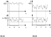
- FIGS. 3A, 3B show the load changes caused by wind loads in a wind turbine. This is-even with average constant wind loads, for example over a period of several minutes-varying load conditions, which are typically subject to stochastic variation. This situation is in the FIGS. 3A, 3B shown.
- Fig. 3A again shows the conditions in an initial state and the Fig. 3B the conditions after a certain period of operation and wear.
- the lower half of the figure shows the course of the load status.
- a measurement period .DELTA.T now a plurality of individual measurements are performed, so that a course of the distances a over time is determined. It Therefore, as a result of the multiplicity of measurements, a continuous course of the distance values, which vary with the course of the variation of the load states L, is quasi ascertained. Both the change of the load state L and the distances a are therefore time-dependent functions.
- the detected values of the distance a are subjected to a statistical evaluation, which leads to a statistical characteristic which is at least a measure of the differences ⁇ a of the distances a in the plurality of individual measurements.
- This statistical characteristic is, for example, in the simplest case, an average value.
- a deviation for example a standard deviation or a variance of the mean value, is used as the characteristic value for the evaluation.
- a wear in addition to a change in the mean also leads to a significant increase in deviation or variance from the mean.
- This (statistical) characteristic value is taken from evaluation parameters for the assessment of changes in the bearing clearance.
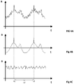
- a course of the distances a over time is shown as an example, namely between the times t1, t2, which define exactly one period, ie one complete revolution of the rotor 12 about the axis of rotation 16.
- the times t1, t2 clear rashes can be seen upwards. These are deliberately caused by corresponding markings in the form of elevations or depressions within the measuring surface.
- Fig. 4A a course in the detection of a plurality of distances for at least one period is shown, wherein in addition to load-dependent changes in distance and the production-related distance changes are superimposed.
- Fig. 4B is shown as a reference curve, the course of the distances a as a result of only manufacturing deviations. This reference measurement is carried out in particular in a no-load condition.
- the reference curve is determined according to Fig. 4Bb from the measured curve according to Fig. 4A deducted. It is then a purely load-related distance course obtained (corrected course), as exemplified in the Fig. 4C is shown. This will then be used for further evaluation. That is, within the scope of a second measurement series at a later point in time, a corrected load-dependent course is again determined and, as described above, the two distance courses are evaluated with regard to the changes of the differences of the distance values.
- the first montage- or production-related deviations such as plan and concentricity errors.
- This can be caused for example by wear or release of biasing elements.
- setting in assembly joints eg bearing seat
- production-related deviations and changes in distance are expediently also monitored or recorded.
- the reference profile determined within this new reference measurement is then subtracted from the distance profile measured in the second measurement series in order to obtain the pure load-dependent course of the distance values a.
- the corrected distance courses according to the two measurement series then become - comparable to that in the Fig. 3A, 3B evaluated evaluated methods.
Landscapes
- Physics & Mathematics (AREA)
- General Physics & Mathematics (AREA)
- Testing Of Devices, Machine Parts, Or Other Structures Thereof (AREA)
- Rolling Contact Bearings (AREA)
Priority Applications (1)
| Application Number | Priority Date | Filing Date | Title |
|---|---|---|---|
| PL18204784T PL3483581T3 (pl) | 2017-11-08 | 2018-11-07 | Sposób i urządzenie do kontrolowania luzu łożyskowego łożysk tocznych |
Applications Claiming Priority (1)
| Application Number | Priority Date | Filing Date | Title |
|---|---|---|---|
| DE102017219887 | 2017-11-08 |
Publications (2)
| Publication Number | Publication Date |
|---|---|
| EP3483581A1 true EP3483581A1 (fr) | 2019-05-15 |
| EP3483581B1 EP3483581B1 (fr) | 2020-02-26 |
Family
ID=64183889
Family Applications (1)
| Application Number | Title | Priority Date | Filing Date |
|---|---|---|---|
| EP18204784.5A Active EP3483581B1 (fr) | 2017-11-08 | 2018-11-07 | Methode et dispositif permettant de surveiller le jeu de palier de roulements a rouleaux |
Country Status (5)
| Country | Link |
|---|---|
| EP (1) | EP3483581B1 (fr) |
| DK (1) | DK3483581T3 (fr) |
| ES (1) | ES2793651T3 (fr) |
| PL (1) | PL3483581T3 (fr) |
| PT (1) | PT3483581T (fr) |
Cited By (10)
| Publication number | Priority date | Publication date | Assignee | Title |
|---|---|---|---|---|
| CN111272426A (zh) * | 2020-03-25 | 2020-06-12 | 新昌县善力机械科技有限公司 | 一种大型轴承加工转动模拟测试装置 |
| US10975908B1 (en) * | 2019-10-29 | 2021-04-13 | Schaeffler Monitoring Services Gmbh | Method and device for monitoring a bearing clearance of roller bearings |
| CN112879535A (zh) * | 2021-01-13 | 2021-06-01 | 广东韶钢松山股份有限公司 | 一种烧结机驱动机构排障方法及烧结机驱动机构排障装置 |
| CN113124810A (zh) * | 2019-12-31 | 2021-07-16 | 新疆金风科技股份有限公司 | 轴系轴承的配合质量测量方法及测量系统 |
| AT524361A3 (de) * | 2020-10-26 | 2022-07-15 | Skf Ab | Wälzlageranordnung |
| CN115855494A (zh) * | 2022-11-24 | 2023-03-28 | 杭州长河动力技术有限公司 | 一种气悬浮推力轴承状态监测装置及其控制系统 |
| CN117864282A (zh) * | 2023-12-27 | 2024-04-12 | 句容志新精密五金零件有限公司 | 一种基于距离感应的集成式智能碗组 |
| DE102023113288A1 (de) * | 2023-05-22 | 2024-11-28 | Ifm Electronic Gmbh | Sensoranordnung zur Lagerverschleißerkennung |
| DE102023113287A1 (de) * | 2023-05-22 | 2024-11-28 | Ifm Electronic Gmbh | Sensoranordnung zur Lagerverschleißerkennung |
| AT526890A5 (de) * | 2022-01-10 | 2025-03-15 | Skf Ab | Wälzlageranordnung |
Families Citing this family (1)
| Publication number | Priority date | Publication date | Assignee | Title |
|---|---|---|---|---|
| DE102023118260A1 (de) * | 2023-07-11 | 2025-01-16 | Liebherr-Components Biberach Gmbh | Großwälzlager sowie Verfahren und Vorrichtung zur Überwachung eines solchen Großwälzlagers |
Citations (5)
| Publication number | Priority date | Publication date | Assignee | Title |
|---|---|---|---|---|
| DE10324924A1 (de) * | 2003-06-03 | 2004-12-23 | Ab Skf | Gleitlager mit sphärisch oder zylinderisch ausgebildeten Lagerflächen |
| DE102009051498A1 (de) | 2009-10-30 | 2011-05-05 | Schaeffler Technologies Gmbh & Co. Kg | Wälzlageranordnung |
| CH702986A2 (de) * | 2010-05-07 | 2011-11-15 | Man Diesel & Turbo Deutschland | Verbesserte Überwachung des Verschleisses von Lagern in einem Zweitakt-Grossdieselmotor. |
| DE102010035264A1 (de) | 2010-08-24 | 2012-03-01 | Schaeffler Technologies Gmbh & Co. Kg | Vorrichtung zur Axialspieleinstellung an einem Schrägwälzlager mit radial wirkenden Piezo-Aktuatoren |
| EP2801729A2 (fr) | 2013-05-06 | 2014-11-12 | Eolotec GmbH | Grand palier, en particulier palier principal d'une éolienne et procédé de détermination d'un jeu de palier d'un palier à roulement et éolienne |
Family Cites Families (14)
| Publication number | Priority date | Publication date | Assignee | Title |
|---|---|---|---|---|
| FR2365780A1 (fr) | 1976-09-24 | 1978-04-21 | Semt | Procede et dispositif de detection d'usure des paliers d'un arbre rotatif, et arbre pourvu d'un tel dispositif |
| US6070325A (en) | 1996-11-05 | 2000-06-06 | Koyo Seiko Co., Ltd. | Method for measuring a pre-load applied to a double-row rolling bearing |
| DE19919006C2 (de) | 1999-04-27 | 2003-08-14 | Fag Kugelfischer Ag & Co Kg | Einrichtung zum Messen von Lagerdaten |
| JP4269669B2 (ja) | 2002-12-05 | 2009-05-27 | 日本精工株式会社 | 転がり軸受ユニット用荷重測定装置 |
| DE20316544U1 (de) | 2003-10-28 | 2005-03-10 | Liebherr-Werk Biberach Gmbh | Überwachungsvorrichtung zur Überwachung von Großwälzlagern |
| DE102007026569B4 (de) | 2007-06-08 | 2013-07-11 | Koenig & Bauer Aktiengesellschaft | Verfahren zur Ermittlung von Lagerschäden an einem Zylinder einer Rotationsdruckmaschine |
| US9746304B2 (en) | 2012-05-16 | 2017-08-29 | Faro Technologies, Inc. | Apparatus and method to compensate bearing runout in an articulated arm coordinate measurement machine |
| DE202012011902U1 (de) | 2012-12-12 | 2013-01-21 | Imo Holding Gmbh | Momentenlager mit Abstandssensorik für Condition Monitoring System(e) |
| CZ2013208A3 (cs) | 2013-03-22 | 2014-08-27 | Rieter Cz S.R.O. | Způsob korekce odchylek parametrů komponent a/nebo sestavy aktivního magnetického ložiska a aktivní magnetické ložisko pro uložení otáčejícího se pracovního prostředku |
| JP6308922B2 (ja) | 2014-09-17 | 2018-04-11 | Ntn株式会社 | 転がり軸受の異常診断装置、風力発電装置、及び転がり軸受の異常診断方法 |
| DE102014014039B4 (de) | 2014-09-26 | 2019-10-24 | Minebea Mitsumi Inc. | Verfahren zur Messung des nicht wiederholbaren Schlages an rotierenden Bauteilen |
| WO2016096418A1 (fr) | 2014-12-16 | 2016-06-23 | Aktiebolaget Skf | Système de détermination de charge pour un palier d'élément roulant |
| JP6605865B2 (ja) | 2015-07-22 | 2019-11-13 | Ntn株式会社 | 転がり軸受の状態監視装置及び転がり軸受の状態監視方法 |
| EP3208571B1 (fr) | 2016-02-18 | 2018-12-05 | Siemens Aktiengesellschaft | Système de jauge de palier |
-
2018
- 2018-11-07 ES ES18204784T patent/ES2793651T3/es active Active
- 2018-11-07 PT PT182047845T patent/PT3483581T/pt unknown
- 2018-11-07 EP EP18204784.5A patent/EP3483581B1/fr active Active
- 2018-11-07 PL PL18204784T patent/PL3483581T3/pl unknown
- 2018-11-07 DK DK18204784.5T patent/DK3483581T3/da active
Patent Citations (5)
| Publication number | Priority date | Publication date | Assignee | Title |
|---|---|---|---|---|
| DE10324924A1 (de) * | 2003-06-03 | 2004-12-23 | Ab Skf | Gleitlager mit sphärisch oder zylinderisch ausgebildeten Lagerflächen |
| DE102009051498A1 (de) | 2009-10-30 | 2011-05-05 | Schaeffler Technologies Gmbh & Co. Kg | Wälzlageranordnung |
| CH702986A2 (de) * | 2010-05-07 | 2011-11-15 | Man Diesel & Turbo Deutschland | Verbesserte Überwachung des Verschleisses von Lagern in einem Zweitakt-Grossdieselmotor. |
| DE102010035264A1 (de) | 2010-08-24 | 2012-03-01 | Schaeffler Technologies Gmbh & Co. Kg | Vorrichtung zur Axialspieleinstellung an einem Schrägwälzlager mit radial wirkenden Piezo-Aktuatoren |
| EP2801729A2 (fr) | 2013-05-06 | 2014-11-12 | Eolotec GmbH | Grand palier, en particulier palier principal d'une éolienne et procédé de détermination d'un jeu de palier d'un palier à roulement et éolienne |
Cited By (15)
| Publication number | Priority date | Publication date | Assignee | Title |
|---|---|---|---|---|
| US10975908B1 (en) * | 2019-10-29 | 2021-04-13 | Schaeffler Monitoring Services Gmbh | Method and device for monitoring a bearing clearance of roller bearings |
| CN113124810A (zh) * | 2019-12-31 | 2021-07-16 | 新疆金风科技股份有限公司 | 轴系轴承的配合质量测量方法及测量系统 |
| CN111272426B (zh) * | 2020-03-25 | 2021-05-07 | 山东瑞新轴承制造有限公司 | 一种大型轴承加工转动模拟测试装置 |
| CN111272426A (zh) * | 2020-03-25 | 2020-06-12 | 新昌县善力机械科技有限公司 | 一种大型轴承加工转动模拟测试装置 |
| AT524361A3 (de) * | 2020-10-26 | 2022-07-15 | Skf Ab | Wälzlageranordnung |
| US11624407B2 (en) | 2020-10-26 | 2023-04-11 | Aktiebolaget Skf | Rolling bearing assembly |
| AT524361B1 (de) * | 2020-10-26 | 2023-07-15 | Skf Ab | Wälzlageranordnung |
| CN112879535A (zh) * | 2021-01-13 | 2021-06-01 | 广东韶钢松山股份有限公司 | 一种烧结机驱动机构排障方法及烧结机驱动机构排障装置 |
| AT526890A5 (de) * | 2022-01-10 | 2025-03-15 | Skf Ab | Wälzlageranordnung |
| AT526890B1 (de) * | 2022-01-10 | 2025-10-15 | Skf Ab | Wälzlageranordnung |
| CN115855494A (zh) * | 2022-11-24 | 2023-03-28 | 杭州长河动力技术有限公司 | 一种气悬浮推力轴承状态监测装置及其控制系统 |
| CN115855494B (zh) * | 2022-11-24 | 2025-10-21 | 杭州长河动力技术有限公司 | 一种气悬浮推力轴承状态监测装置及其控制系统 |
| DE102023113287A1 (de) * | 2023-05-22 | 2024-11-28 | Ifm Electronic Gmbh | Sensoranordnung zur Lagerverschleißerkennung |
| DE102023113288A1 (de) * | 2023-05-22 | 2024-11-28 | Ifm Electronic Gmbh | Sensoranordnung zur Lagerverschleißerkennung |
| CN117864282A (zh) * | 2023-12-27 | 2024-04-12 | 句容志新精密五金零件有限公司 | 一种基于距离感应的集成式智能碗组 |
Also Published As
| Publication number | Publication date |
|---|---|
| EP3483581B1 (fr) | 2020-02-26 |
| PL3483581T3 (pl) | 2020-07-13 |
| ES2793651T3 (es) | 2020-11-16 |
| DK3483581T3 (da) | 2020-06-02 |
| PT3483581T (pt) | 2020-06-01 |
Similar Documents
| Publication | Publication Date | Title |
|---|---|---|
| EP3483581B1 (fr) | Methode et dispositif permettant de surveiller le jeu de palier de roulements a rouleaux | |
| EP2801729B1 (fr) | Grand palier, en particulier palier principal d'une éolienne et procédé de détermination d'un jeu de palier d'un palier à roulement et éolienne | |
| EP3343030B1 (fr) | Dispositif et procédé de surveillance d'un palier de pale d'une éolienne | |
| DE112017002650B4 (de) | Vorrichtung zur Vorhersage des Ermüdungszustands von Wälzlagern | |
| EP2927662B1 (fr) | Procédé et système de surveillance de l'état d'un palier de roulement d'une éolienne | |
| DE19937203A1 (de) | Überwachung der Lebensdauer und der Belastung von Lagern | |
| DE19938722B4 (de) | Verfahren und Vorrichtung zur Analyse von Wälzlagern in Maschinen | |
| EP2131178B1 (fr) | Procédé de diagnostic pour au moins un roulement à billes, en particulier pour un palier à billes oblique, système de diagnostic correspondant et utilisation d'un tel système de diagnostic | |
| EP2771583B1 (fr) | Bague de roulement, segment de bague de roulement, roulement et procédé de réglage de la précontrainte d'un palier à roulement | |
| WO2014101983A1 (fr) | Ensemble d'elements pour une eolienne, procede de montage et de fonctionnement | |
| EP2431622A1 (fr) | Palier à roulement tournant | |
| EP3472459B1 (fr) | Procédé de surveillance d'un réglage de pales de rotor | |
| DE102019104791A1 (de) | Verfahren zur Einstellung der Vorspannung einer zweireihigen Wälzlagerung | |
| EP1457274A2 (fr) | Procédé et dispositif pour éviter des vibrations | |
| DE102017131241A1 (de) | Überwachungsverfahren für eine Windkraftanlage, zugehörige Überwachungsvorrichtung sowie Windkraftanlage mit Überwachungsvorrichtung | |
| WO2018134401A1 (fr) | Dispositif de mesure et procédé de mesure de détection d'événements de frottement mixte et/ou d'événements de broutage | |
| DE102016220195A1 (de) | Verfahren und Messanordnung zur Erfassung von Schlupf bei Wälzlagern | |
| WO2012072603A1 (fr) | Concept de réglage de paramètres d'un processus de laminage au moyen d'un glissement de palier mesuré | |
| DE102016217943A1 (de) | Lager mit mindestens zwei Dehnungsmessfühlern | |
| DE102013208480A1 (de) | Verfahren zur Einstellung der Vorspannung in einer Lageranordnung | |
| DE102020216210B4 (de) | System und Verfahren zur thermischen Überwachung großer Wälzlager | |
| DE102010009634B4 (de) | Verfahren zur Einstellung und Messung einer Vorspannung einer radial zwischen einem Planetenrad und einem Planetenträger angeordneten Lageranordnung | |
| DE102021125852A1 (de) | Verfahren zum Bestimmen einer Ausdehnung eines Schadens in einem Lager | |
| DE102014204539B4 (de) | Verfahren zur Bestimmung der Vorspannung in einem Wälzlager und Wälzlager | |
| EP4309817B1 (fr) | Procédé et programme informatique pour surveiller l'état d'une cage de laminoir |
Legal Events
| Date | Code | Title | Description |
|---|---|---|---|
| PUAI | Public reference made under article 153(3) epc to a published international application that has entered the european phase |
Free format text: ORIGINAL CODE: 0009012 |
|
| STAA | Information on the status of an ep patent application or granted ep patent |
Free format text: STATUS: THE APPLICATION HAS BEEN PUBLISHED |
|
| AK | Designated contracting states |
Kind code of ref document: A1 Designated state(s): AL AT BE BG CH CY CZ DE DK EE ES FI FR GB GR HR HU IE IS IT LI LT LU LV MC MK MT NL NO PL PT RO RS SE SI SK SM TR |
|
| AX | Request for extension of the european patent |
Extension state: BA ME |
|
| STAA | Information on the status of an ep patent application or granted ep patent |
Free format text: STATUS: REQUEST FOR EXAMINATION WAS MADE |
|
| 17P | Request for examination filed |
Effective date: 20190513 |
|
| RBV | Designated contracting states (corrected) |
Designated state(s): AL AT BE BG CH CY CZ DE DK EE ES FI FR GB GR HR HU IE IS IT LI LT LU LV MC MK MT NL NO PL PT RO RS SE SI SK SM TR |
|
| GRAP | Despatch of communication of intention to grant a patent |
Free format text: ORIGINAL CODE: EPIDOSNIGR1 |
|
| STAA | Information on the status of an ep patent application or granted ep patent |
Free format text: STATUS: GRANT OF PATENT IS INTENDED |
|
| INTG | Intention to grant announced |
Effective date: 20190828 |
|
| GRAS | Grant fee paid |
Free format text: ORIGINAL CODE: EPIDOSNIGR3 |
|
| GRAA | (expected) grant |
Free format text: ORIGINAL CODE: 0009210 |
|
| STAA | Information on the status of an ep patent application or granted ep patent |
Free format text: STATUS: THE PATENT HAS BEEN GRANTED |
|
| AK | Designated contracting states |
Kind code of ref document: B1 Designated state(s): AL AT BE BG CH CY CZ DE DK EE ES FI FR GB GR HR HU IE IS IT LI LT LU LV MC MK MT NL NO PL PT RO RS SE SI SK SM TR |
|
| REG | Reference to a national code |
Ref country code: GB Ref legal event code: FG4D Free format text: NOT ENGLISH |
|
| REG | Reference to a national code |
Ref country code: CH Ref legal event code: EP |
|
| REG | Reference to a national code |
Ref country code: DE Ref legal event code: R096 Ref document number: 502018000840 Country of ref document: DE |
|
| REG | Reference to a national code |
Ref country code: AT Ref legal event code: REF Ref document number: 1238234 Country of ref document: AT Kind code of ref document: T Effective date: 20200315 |
|
| REG | Reference to a national code |
Ref country code: IE Ref legal event code: FG4D Free format text: LANGUAGE OF EP DOCUMENT: GERMAN |
|
| REG | Reference to a national code |
Ref country code: PT Ref legal event code: SC4A Ref document number: 3483581 Country of ref document: PT Date of ref document: 20200601 Kind code of ref document: T Free format text: AVAILABILITY OF NATIONAL TRANSLATION Effective date: 20200525 |
|
| REG | Reference to a national code |
Ref country code: DK Ref legal event code: T3 Effective date: 20200528 |
|
| REG | Reference to a national code |
Ref country code: NL Ref legal event code: FP |
|
| RAP2 | Party data changed (patent owner data changed or rights of a patent transferred) |
Owner name: SCHAEFFLER MONITORING SERVICES GMBH |
|
| REG | Reference to a national code |
Ref country code: NL Ref legal event code: PD Owner name: SCHAEFFLER MONITORING SERVICES GMBH; DE Free format text: DETAILS ASSIGNMENT: CHANGE OF OWNER(S), ASSIGNMENT; FORMER OWNER NAME: EOLOTEC GMBH Effective date: 20200526 |
|
| REG | Reference to a national code |
Ref country code: NO Ref legal event code: T2 Effective date: 20200226 Ref country code: DE Ref legal event code: R081 Ref document number: 502018000840 Country of ref document: DE Owner name: SCHAEFFLER MONITORING SERVICES GMBH, DE Free format text: FORMER OWNER: EOLOTEC GMBH, 90429 NUERNBERG, DE |
|
| PG25 | Lapsed in a contracting state [announced via postgrant information from national office to epo] |
Ref country code: RS Free format text: LAPSE BECAUSE OF FAILURE TO SUBMIT A TRANSLATION OF THE DESCRIPTION OR TO PAY THE FEE WITHIN THE PRESCRIBED TIME-LIMIT Effective date: 20200226 Ref country code: FI Free format text: LAPSE BECAUSE OF FAILURE TO SUBMIT A TRANSLATION OF THE DESCRIPTION OR TO PAY THE FEE WITHIN THE PRESCRIBED TIME-LIMIT Effective date: 20200226 |
|
| REG | Reference to a national code |
Ref country code: LT Ref legal event code: MG4D |
|
| PG25 | Lapsed in a contracting state [announced via postgrant information from national office to epo] |
Ref country code: LV Free format text: LAPSE BECAUSE OF FAILURE TO SUBMIT A TRANSLATION OF THE DESCRIPTION OR TO PAY THE FEE WITHIN THE PRESCRIBED TIME-LIMIT Effective date: 20200226 Ref country code: BG Free format text: LAPSE BECAUSE OF FAILURE TO SUBMIT A TRANSLATION OF THE DESCRIPTION OR TO PAY THE FEE WITHIN THE PRESCRIBED TIME-LIMIT Effective date: 20200526 Ref country code: IS Free format text: LAPSE BECAUSE OF FAILURE TO SUBMIT A TRANSLATION OF THE DESCRIPTION OR TO PAY THE FEE WITHIN THE PRESCRIBED TIME-LIMIT Effective date: 20200626 Ref country code: SE Free format text: LAPSE BECAUSE OF FAILURE TO SUBMIT A TRANSLATION OF THE DESCRIPTION OR TO PAY THE FEE WITHIN THE PRESCRIBED TIME-LIMIT Effective date: 20200226 Ref country code: HR Free format text: LAPSE BECAUSE OF FAILURE TO SUBMIT A TRANSLATION OF THE DESCRIPTION OR TO PAY THE FEE WITHIN THE PRESCRIBED TIME-LIMIT Effective date: 20200226 Ref country code: GR Free format text: LAPSE BECAUSE OF FAILURE TO SUBMIT A TRANSLATION OF THE DESCRIPTION OR TO PAY THE FEE WITHIN THE PRESCRIBED TIME-LIMIT Effective date: 20200527 |
|
| REG | Reference to a national code |
Ref country code: GB Ref legal event code: 732E Free format text: REGISTERED BETWEEN 20200806 AND 20200812 |
|
| PG25 | Lapsed in a contracting state [announced via postgrant information from national office to epo] |
Ref country code: CZ Free format text: LAPSE BECAUSE OF FAILURE TO SUBMIT A TRANSLATION OF THE DESCRIPTION OR TO PAY THE FEE WITHIN THE PRESCRIBED TIME-LIMIT Effective date: 20200226 Ref country code: SK Free format text: LAPSE BECAUSE OF FAILURE TO SUBMIT A TRANSLATION OF THE DESCRIPTION OR TO PAY THE FEE WITHIN THE PRESCRIBED TIME-LIMIT Effective date: 20200226 Ref country code: EE Free format text: LAPSE BECAUSE OF FAILURE TO SUBMIT A TRANSLATION OF THE DESCRIPTION OR TO PAY THE FEE WITHIN THE PRESCRIBED TIME-LIMIT Effective date: 20200226 Ref country code: LT Free format text: LAPSE BECAUSE OF FAILURE TO SUBMIT A TRANSLATION OF THE DESCRIPTION OR TO PAY THE FEE WITHIN THE PRESCRIBED TIME-LIMIT Effective date: 20200226 Ref country code: RO Free format text: LAPSE BECAUSE OF FAILURE TO SUBMIT A TRANSLATION OF THE DESCRIPTION OR TO PAY THE FEE WITHIN THE PRESCRIBED TIME-LIMIT Effective date: 20200226 Ref country code: SM Free format text: LAPSE BECAUSE OF FAILURE TO SUBMIT A TRANSLATION OF THE DESCRIPTION OR TO PAY THE FEE WITHIN THE PRESCRIBED TIME-LIMIT Effective date: 20200226 |
|
| REG | Reference to a national code |
Ref country code: ES Ref legal event code: FG2A Ref document number: 2793651 Country of ref document: ES Kind code of ref document: T3 Effective date: 20201116 |
|
| REG | Reference to a national code |
Ref country code: DE Ref legal event code: R026 Ref document number: 502018000840 Country of ref document: DE |
|
| PLBI | Opposition filed |
Free format text: ORIGINAL CODE: 0009260 |
|
| PLAX | Notice of opposition and request to file observation + time limit sent |
Free format text: ORIGINAL CODE: EPIDOSNOBS2 |
|
| 26 | Opposition filed |
Opponent name: NORDEX ENERGY SE & CO. KG Effective date: 20201126 |
|
| PG25 | Lapsed in a contracting state [announced via postgrant information from national office to epo] |
Ref country code: IT Free format text: LAPSE BECAUSE OF FAILURE TO SUBMIT A TRANSLATION OF THE DESCRIPTION OR TO PAY THE FEE WITHIN THE PRESCRIBED TIME-LIMIT Effective date: 20200226 |
|
| PG25 | Lapsed in a contracting state [announced via postgrant information from national office to epo] |
Ref country code: SI Free format text: LAPSE BECAUSE OF FAILURE TO SUBMIT A TRANSLATION OF THE DESCRIPTION OR TO PAY THE FEE WITHIN THE PRESCRIBED TIME-LIMIT Effective date: 20200226 |
|
| PLBB | Reply of patent proprietor to notice(s) of opposition received |
Free format text: ORIGINAL CODE: EPIDOSNOBS3 |
|
| PG25 | Lapsed in a contracting state [announced via postgrant information from national office to epo] |
Ref country code: MC Free format text: LAPSE BECAUSE OF FAILURE TO SUBMIT A TRANSLATION OF THE DESCRIPTION OR TO PAY THE FEE WITHIN THE PRESCRIBED TIME-LIMIT Effective date: 20200226 |
|
| PG25 | Lapsed in a contracting state [announced via postgrant information from national office to epo] |
Ref country code: LU Free format text: LAPSE BECAUSE OF NON-PAYMENT OF DUE FEES Effective date: 20201107 |
|
| REG | Reference to a national code |
Ref country code: BE Ref legal event code: MM Effective date: 20201130 |
|
| PG25 | Lapsed in a contracting state [announced via postgrant information from national office to epo] |
Ref country code: IE Free format text: LAPSE BECAUSE OF NON-PAYMENT OF DUE FEES Effective date: 20201107 |
|
| PG25 | Lapsed in a contracting state [announced via postgrant information from national office to epo] |
Ref country code: TR Free format text: LAPSE BECAUSE OF FAILURE TO SUBMIT A TRANSLATION OF THE DESCRIPTION OR TO PAY THE FEE WITHIN THE PRESCRIBED TIME-LIMIT Effective date: 20200226 Ref country code: MT Free format text: LAPSE BECAUSE OF FAILURE TO SUBMIT A TRANSLATION OF THE DESCRIPTION OR TO PAY THE FEE WITHIN THE PRESCRIBED TIME-LIMIT Effective date: 20200226 Ref country code: CY Free format text: LAPSE BECAUSE OF FAILURE TO SUBMIT A TRANSLATION OF THE DESCRIPTION OR TO PAY THE FEE WITHIN THE PRESCRIBED TIME-LIMIT Effective date: 20200226 |
|
| PG25 | Lapsed in a contracting state [announced via postgrant information from national office to epo] |
Ref country code: MK Free format text: LAPSE BECAUSE OF FAILURE TO SUBMIT A TRANSLATION OF THE DESCRIPTION OR TO PAY THE FEE WITHIN THE PRESCRIBED TIME-LIMIT Effective date: 20200226 Ref country code: AL Free format text: LAPSE BECAUSE OF FAILURE TO SUBMIT A TRANSLATION OF THE DESCRIPTION OR TO PAY THE FEE WITHIN THE PRESCRIBED TIME-LIMIT Effective date: 20200226 |
|
| REG | Reference to a national code |
Ref country code: CH Ref legal event code: PL |
|
| PG25 | Lapsed in a contracting state [announced via postgrant information from national office to epo] |
Ref country code: BE Free format text: LAPSE BECAUSE OF NON-PAYMENT OF DUE FEES Effective date: 20201130 |
|
| PG25 | Lapsed in a contracting state [announced via postgrant information from national office to epo] |
Ref country code: LI Free format text: LAPSE BECAUSE OF NON-PAYMENT OF DUE FEES Effective date: 20211130 Ref country code: CH Free format text: LAPSE BECAUSE OF NON-PAYMENT OF DUE FEES Effective date: 20211130 |
|
| APBM | Appeal reference recorded |
Free format text: ORIGINAL CODE: EPIDOSNREFNO |
|
| APBP | Date of receipt of notice of appeal recorded |
Free format text: ORIGINAL CODE: EPIDOSNNOA2O |
|
| APAH | Appeal reference modified |
Free format text: ORIGINAL CODE: EPIDOSCREFNO |
|
| REG | Reference to a national code |
Ref country code: AT Ref legal event code: MM01 Ref document number: 1238234 Country of ref document: AT Kind code of ref document: T Effective date: 20231107 |
|
| APBU | Appeal procedure closed |
Free format text: ORIGINAL CODE: EPIDOSNNOA9O |
|
| PG25 | Lapsed in a contracting state [announced via postgrant information from national office to epo] |
Ref country code: AT Free format text: LAPSE BECAUSE OF NON-PAYMENT OF DUE FEES Effective date: 20231107 |
|
| PG25 | Lapsed in a contracting state [announced via postgrant information from national office to epo] |
Ref country code: AT Free format text: LAPSE BECAUSE OF NON-PAYMENT OF DUE FEES Effective date: 20231107 |
|
| PGFP | Annual fee paid to national office [announced via postgrant information from national office to epo] |
Ref country code: PT Payment date: 20251028 Year of fee payment: 8 |
|
| PGFP | Annual fee paid to national office [announced via postgrant information from national office to epo] |
Ref country code: NL Payment date: 20251119 Year of fee payment: 8 |
|
| PGFP | Annual fee paid to national office [announced via postgrant information from national office to epo] |
Ref country code: DE Payment date: 20251124 Year of fee payment: 8 |
|
| PGFP | Annual fee paid to national office [announced via postgrant information from national office to epo] |
Ref country code: GB Payment date: 20251120 Year of fee payment: 8 |
|
| PGFP | Annual fee paid to national office [announced via postgrant information from national office to epo] |
Ref country code: NO Payment date: 20251118 Year of fee payment: 8 |
|
| PGFP | Annual fee paid to national office [announced via postgrant information from national office to epo] |
Ref country code: DK Payment date: 20251119 Year of fee payment: 8 |
|
| PGFP | Annual fee paid to national office [announced via postgrant information from national office to epo] |
Ref country code: FR Payment date: 20251125 Year of fee payment: 8 |
|
| PGFP | Annual fee paid to national office [announced via postgrant information from national office to epo] |
Ref country code: PL Payment date: 20251024 Year of fee payment: 8 |
|
| PGFP | Annual fee paid to national office [announced via postgrant information from national office to epo] |
Ref country code: ES Payment date: 20251216 Year of fee payment: 8 |
|
| PGFP | Annual fee paid to national office [announced via postgrant information from national office to epo] |
Ref country code: AT Payment date: 20260410 Year of fee payment: 5 |