EP3483996A1 - Anordnung für eine kabeldurchführung - Google Patents
Anordnung für eine kabeldurchführung Download PDFInfo
- Publication number
- EP3483996A1 EP3483996A1 EP18205450.2A EP18205450A EP3483996A1 EP 3483996 A1 EP3483996 A1 EP 3483996A1 EP 18205450 A EP18205450 A EP 18205450A EP 3483996 A1 EP3483996 A1 EP 3483996A1
- Authority
- EP
- European Patent Office
- Prior art keywords
- cable
- strain relief
- arrangement according
- component
- sealing portion
- Prior art date
- Legal status (The legal status is an assumption and is not a legal conclusion. Google has not performed a legal analysis and makes no representation as to the accuracy of the status listed.)
- Granted
Links
Images




Classifications
-
- H—ELECTRICITY
- H01—ELECTRIC ELEMENTS
- H01B—CABLES; CONDUCTORS; INSULATORS; SELECTION OF MATERIALS FOR THEIR CONDUCTIVE, INSULATING OR DIELECTRIC PROPERTIES
- H01B17/00—Insulators or insulating bodies characterised by their form
- H01B17/26—Lead-in insulators; Lead-through insulators
- H01B17/30—Sealing
-
- H—ELECTRICITY
- H02—GENERATION; CONVERSION OR DISTRIBUTION OF ELECTRIC POWER
- H02G—INSTALLATION OF ELECTRIC CABLES OR LINES, OR OF COMBINED OPTICAL AND ELECTRIC CABLES OR LINES
- H02G3/00—Installations of electric cables or lines or protective tubing therefor in or on buildings, equivalent structures or vehicles
- H02G3/02—Details
- H02G3/06—Joints for connecting lengths of protective tubing or channels, to each other or to casings, e.g. to distribution boxes; Ensuring electrical continuity in the joint
- H02G3/0616—Joints for connecting tubing to casing
- H02G3/0625—Joints for connecting tubing to casing with means for preventing disengagement of conductors
- H02G3/0658—Joints for connecting tubing to casing with means for preventing disengagement of conductors with means constricting the conductor-insulation
-
- H—ELECTRICITY
- H01—ELECTRIC ELEMENTS
- H01B—CABLES; CONDUCTORS; INSULATORS; SELECTION OF MATERIALS FOR THEIR CONDUCTIVE, INSULATING OR DIELECTRIC PROPERTIES
- H01B17/00—Insulators or insulating bodies characterised by their form
- H01B17/02—Suspension insulators; Strain insulators
-
- H—ELECTRICITY
- H02—GENERATION; CONVERSION OR DISTRIBUTION OF ELECTRIC POWER
- H02G—INSTALLATION OF ELECTRIC CABLES OR LINES, OR OF COMBINED OPTICAL AND ELECTRIC CABLES OR LINES
- H02G3/00—Installations of electric cables or lines or protective tubing therefor in or on buildings, equivalent structures or vehicles
- H02G3/02—Details
- H02G3/06—Joints for connecting lengths of protective tubing or channels, to each other or to casings, e.g. to distribution boxes; Ensuring electrical continuity in the joint
- H02G3/0616—Joints for connecting tubing to casing
-
- H—ELECTRICITY
- H02—GENERATION; CONVERSION OR DISTRIBUTION OF ELECTRIC POWER
- H02G—INSTALLATION OF ELECTRIC CABLES OR LINES, OR OF COMBINED OPTICAL AND ELECTRIC CABLES OR LINES
- H02G3/00—Installations of electric cables or lines or protective tubing therefor in or on buildings, equivalent structures or vehicles
- H02G3/22—Installations of cables or lines through walls, floors or ceilings, e.g. into buildings
Definitions
- Cable glands or inlets serve to insert one or more cables through a breakthrough or opening in a housing wall in a housing, such as a cabinet enclosure.
- WO 2016/177364 A1 describes an arrangement with a wall feedthrough for several cables.
- a plurality of sealing elements are arranged in a housing of a wall feedthrough, each receiving a cable circumferentially sealing.
- the peripherally closed cable entry has a sealing section and a strain relief arranged thereon.
- the sealing portion is formed with a breakthrough in the cable entry closing sealing membrane which is pierced to thereby plug the cable, which is then sealingly surrounded by the sealing membrane.
- the sealing portion is made of a soft elastic material, whereas the strain relief consists of a hard elastic material.
- the object of the invention is to provide an arrangement for a cable bushing or -In Entry, which allows a simple and efficient way a sealing receiving the cable in the cable gland and its installation in a breakthrough or opening of a housing wall, especially in connection with pre-assembled cables ,
- an arrangement for a cable wall bushing is provided by the independent protection claim 1.
- Embodiments are the subject of dependent protection claims.
- an arrangement for a cable gland with a grommet has a sealing portion made of a plastic soft component, which has a breakthrough in the longitudinal direction for sealingly receiving a cable to be carried through a housing wall, and a strain relief of a plastic hard component, which is integrally formed on the sealing portion and in the longitudinal direction a passage for has the cable to be performed, which is aligned with the breakthrough.
- the grommet further has a slot which extends longitudinally of the grommet over the sealing portion and the strain relief and through which the cable to be passed can be inserted from outside in the aperture and the passage from a direction transverse to the longitudinal direction.
- the cable gland can be opened in the region of the slit in order to insert or insert the cable, in particular from the side.
- the cable feedthrough can be designed in several parts, such that component halves of the cable feedthrough each have one half of the sealing section and a half of the strain relief integrally connected thereto.
- the grommet may have two or more component halves, which then each have one half of the sealing portion and a hereby integrally connected half of the strain relief.
- the component halves are separated by means of further slits.
- centering can be provided with which the relative position of the interconnected component halves is fixed.
- the centering device may have a projection on a component half and an associated one Have receptacle for the projection on an opposite half of the component.
- the centering device for example, the projection may consist of the plastic hard component.
- the grommet consists of exactly two component halves, which are formed for example as two half-shells.
- the component halves can be releasably connected to each other by means of a plug connection.
- mutually associated connectors can be arranged on the sealing portion and / or on the strain relief.
- the associated connectors may be, for example, mating snap connectors.
- the mutually associated connectors may be formed from the plastic hard component.
- the component halves can be pivotally connected to one another by means of a hinge connection.
- the cable gland has a securing device with which the hinge connection is secured against unintentional opening, for example with a snap-in, snap in the associated fuse elements when the component halves are interconnected.
- the snap lock is releasable to swing open the hinge connection.
- the hinge connection may be formed with film hinges that extend longitudinally along the grommet adjacent one of the slots.
- the hinge connection may be at least partially made of the plastic soft component. Alternatively or additionally, the hinge connection may consist of the plastic hard component.
- the grommet may be implemented as a two-component injection molded component.
- the plastic soft component and the plastic hard component may be compatible plastic materials.
- An anchoring portion of the strain relief may be disposed on the sealing portion and there at least partially enclosed by the plastic soft component.
- the anchoring portion which may be formed in one or more pieces, may be substantially completely surrounded by the plastic soft component.
- the anchoring portion can radially surround the opening in the sealing section.
- the anchoring portion can encompass the breakthrough circumferentially closed or interrupted radially.
- At least part of the mating connectors may be formed in the sealing portion on the anchoring portion.
- the one or more associated connectors may be integrally formed on the anchoring portion.
- the strain relief may have strain relief claws disposed about the passage.
- the strain relief claws may be resiliently biased against widening of the passage in the region of the strain relief claws, for example by means of one or more respective spring arms with which the strain relief claws are formed.
- 3, 4 or 5 strain relief claws may be arranged around the passage, in particular at equidistant intervals, which may each comprise one or more spring arms.
- the strain relief claws can be supported on a stiffening element of the strain relief on a rear side facing away from the passage.
- the stiffening element may be formed with a stiffening cage, the stiffening struts and arranged therebetween openings or openings, which can optionally make the arranged in the cable gland cable from the outside can be viewed.
- the strain relief claws may be biased against expansion of the passage in the region of the strain relief claws by means of a stop on an associated yielding support element of the plastic soft component.
- the yielding support member may be circumferentially continuous or interrupted around the passage.
- the yielding support element can in turn be supported on the stiffening element, for example by being arranged thereon.
- the sealing portion may be arranged in an opening of a housing wall. While the sealing portion is arranged in the opening of the housing wall itself, the strain relief can be arranged partially or completely outside the opening of the housing wall on one or the other side of the housing wall. In this case, the strain relief can be arranged free of contact with the housing wall, in particular free from a support on the housing wall, for example in the region of the opening of the housing wall. Outer circumferential surface portions of the sealing portion may be in direct contact with wall portions in the region of the opening of the housing wall and thus form a seal to the housing wall.
- sealing portion in a frame of a wall duct, wherein in the frame, a grid member may be arranged, are provided with the inside of the frame a plurality of receiving pockets for sealing portions of cable glands.
- a wall penetration as such is for example from the document WO 2016/177364 A1 known.
- a prefabricated cable can be arranged, which extends through the opening of the sealing portion and the passage of the strain relief.
- Fig. 1 shows schematic representations of a cable gland 1, which has a sealing portion 2 made of a plastic soft component and a thereto integrally molded strain relief 3.
- the sealing element 2 has an opening 4 for sealingly receiving a cable, in particular a prefabricated cable, in which an electrical or electronic component or component is mounted on at least one end side of the cable.
- the strain relief 3 has along its longitudinal direction on a passage 5 for receiving the cable, which is aligned with the opening 4.
- a slot 6, which is formed in the embodiment shown with partial slots 6a, 6b, so that two component halves 7a, 7b are made, which are releasably connected to each other.
- the sealing element 2 has on an outer surface 8 sealing lips 9, which are circumferentially continuous in the embodiment shown.
- the opening 4 surrounded inner sealing lips 10th
- a stiffening cage 11 is formed, which surrounds the passage 5 radially.
- the strain relief 3 has strain relief claws 12, which are arranged isolated around the passage 5 around and in the embodiment shown in each case a spring arm 12a and a claw 12b (see. Fig. 3 ) respectively.
- Fig. 2 shows another cable feedthrough 20.
- the component halves 7a, 7b are separated from each other.
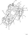
- Fig. 3 shows a perspective view of the component half 7a obliquely from above.
- the component halves 7a, 7b are detachably connected to one another by means of a plug connection, with further associated connectors 22a, 22b being arranged on the component halves 7a, 7b in the region of the sealing element 2 associated connectors 21a, 21b and in the region of the strain relief.
- the connectors 21a, 221b and the other connectors 22a, 22b are each designed as a snap connector in the embodiment shown.
- Connectors 21a, 21b and further connectors 22a, 22b are formed on the component halves 7a, 7b respectively on opposite sides.
- a centering device 23 with centering pins 23a, 23b is provided.
- the centering pin 23a is arranged in an associated receptacle 24.
- the connectors 21a, 21b and the centering pins 23a, 23b may be formed from the plastic hard component. Alternatively, it can be provided to produce the plug connectors 21a, 21b at least partially from the plastic soft component, for example the plug connector 21b with an associated opening 25.
- Fig. 3 shows a perspective view of the component half 7a from above. It follows that the Glasentlastungsklauen 12 are supported in the back of the claw 12 b on a support member 30, which may consist of the plastic soft component and is then yielded, wherein the support member 30 in turn supported on the stiffening cage 11. According to Fig. 3 are in the region of the opening 4 a plurality of inner sealing lips 10 arranged in the axial direction one behind the other.
- Fig. 4 shows a perspective view of an arrangement with the cable gland 1 and a cable 40 received therein.
- Fig. 5 shows a sectional view of the arrangement Fig. 4 , It follows that the strain relief 3 in the region of the sealing element 2 has an anchoring portion 50, on which the strain relief claws 12 is integrally formed, wherein the anchoring portion 50 is substantially completely enclosed by the plastic soft component. If the cable feedthrough 1, 20 produced in a two-component injection molding, the anchoring portion 50, at least partially encapsulated by the plastic soft component.
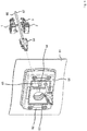
- Fig. 6 shows a schematic perspective view of an arrangement with a wall duct 60, which is arranged on an opening of a housing wall 61.
- the wall bushing 60 has a frame 62, in which a receiving space 63 is formed, which receives a grid member 64, with which several receptacles 65 are provided for one or more sealing sections 2 of cable bushings.
- the sealing portion 2 of the grommet 1 is then sealingly received, so that the pre-assembled cable 66 with cable 67 and component 68 mounted thereon sealingly through the housing wall 61 can be passed.
- the frame 62 is mounted on the housing wall 61 on one side and allows mounting of the cable glands from the opposite side.
Landscapes
- Engineering & Computer Science (AREA)
- Architecture (AREA)
- Civil Engineering (AREA)
- Structural Engineering (AREA)
- Installation Of Indoor Wiring (AREA)
- Details Of Connecting Devices For Male And Female Coupling (AREA)
- Insertion, Bundling And Securing Of Wires For Electric Apparatuses (AREA)
Abstract
Description
- Kabeldurchführungen oder -einführungen dienen dazu, ein oder mehrere Kabel durch einen Durchbruch oder eine Öffnung in einer Gehäusewand in einem Gehäuse einzuführen, beispielsweise einem Schaltschrankgehäuse.
- Im Dokument
DE 20 2016 102 878 U1 ist beispielhaft eine Kabeltülle für eine Kabeldurchführung offenbart. - Das Dokument
WO 2016/177364 A1 beschreibt eine Anordnung mit einer Wanddurchführung für mehrere Kabel. Hierbei werden in einem Gehäuse einer Wanddurchführung mehrere Dichtungselemente angeordnet, die jeweils ein Kabel umlaufend abdichtend aufnehmen. - Im Dokument
DE 10 2007 003 752 A1 ist eine Kabeleinführung mit Zugentlastung offenbart. Die umlaufend geschlossene Kabeleinführung weist einen Dichtabschnitt sowie eine hieran angeordnete Zugentlastung auf. Der Dichtabschnitt ist mit einer den Durchbruch in der Kabeleinführung verschließenden Dichtmembran gebildet, die durchstoßen wird, um hierdurch das Kabel zu stecken, welches dann von der Dichtmembran abdichtend umgeben ist. Der Dichtabschnitt ist aus einem weichelastischen Material, wohingegen die Zugentlastung aus einem hartelastischen Material besteht. Beim Anordnen der Kabeleinführung in einem Durchbruch einer Gehäusewand wird die aus dem hartelastischen Material bestehende Zugentlastung in den Durchbruch eingesteckt oder eingeschraubt. Der Dichtabschnitt befindet sich dann außerhalb des Gehäusedurchbruchs, derart, dass Flansche zur Abdichtung auf der Gehäuseinnenseite oder -außenseite benachbart zum Gehäusedurchbruch aufliegen. - Aufgabe der Erfindung ist es, eine Anordnung für eine Kabeldurchführung oder -Einführung anzugeben, die auf einfache und effiziente Weise eine abdichtende Aufnahme des Kabels in der Kabeldurchführung und deren Montage in einem Durchbruch oder einer Öffnung einer Gehäusewand ermöglicht, insbesondere auch in Verbindung mit vorkonfektionierten Kabeln. Zur Lösung ist eine Anordnung für eine Kabelwanddurchführung nach dem unabhängigen Schutzanspruch 1 geschaffen. Ausgestaltungen sind Gegenstand von abhängigen Schutzansprüchen.
- Nach einem Aspekt ist eine Anordnung für eine Kabelwanddurchführung mit einer Kabeldurchführung geschaffen. Die Kabeldurchführung weist einen Dichtabschnitt aus einer Kunststoff-Weichkomponente, welcher in Längsrichtung einen Durchbruch zum dichtenden Aufnehmen eines durch eine Gehäusewand durchzuführenden Kabels aufweist, und eine Zugentlastung aus einer Kunststoff-Hartkomponente auf, die an den Dichtabschnitt einstückig angeformt ist und in Längsrichtung einen Durchgang für das durchzuführende Kabel aufweist, welcher mit dem Durchbruch fluchtet. Die Kabeldurchführung weist weiterhin eine Schlitzung auf, die sich in Längsrichtung der Kabeldurchführung über den Dichtabschnitt und die Zugentlastung erstreckt und durch die das durchzuführende Kabel von außerhalb in dem Durchbruch und dem Durchgang aus einer Richtung quer zur Längsrichtung eingeführt werden kann.
- Auf diese Weise ist es ermöglicht, dass durch die Gehäusewand hindurchzuführende Kabel in der Kabeldurchführung nicht nur dadurch einzuführen, dass das Kabel stirnseitig eingesteckt wird, sondern auch von der Seite durch die Schlitzung, welche die Kabeldurchführung aufweist. Auf diese Weise ist es insbesondere ermöglicht, die Kabeldurchführung auch für vorkonfektionierte Kabel einzusetzen, bei denen an dem Kabel zumindest an einer Endseite ein elektrisches Bauteil oder -element vormontiert ist. Auf einfache Weise kann die Kabeldurchführung im Bereich der Schlitzung geöffnet werden, um das Kabel einzulegen oder einzuführen, insbesondere von der Seite.
- Die Kabeldurchführung kann mehrteilig ausgeführt sein, derart, dass Bauteilhälften der Kabeldurchführung jeweils eine Hälfte des Dichtabschnitts und eine hiermit einstückig verbundene Hälfte der Zugentlastung aufweisen. Die Kabeldurchführung kann zwei oder mehr Bauteilhälften aufweisen, die dann jeweils eine Hälfte des Dichtabschnitts und eine hiermit eine einstückig verbundene Hälfte der Zugentlastung aufweisen. Die Bauteilhälften sind mittels weiterer Schlitzungen getrennt. Mit Hilfe des Zusammensetzens oder Zusammenfügens bilden die Bauteilhälften die Kabeldurchführung aus. An Bauteilhälften, die hierbei miteinander verbunden werden, können Zentriereinrichtungen vorgesehen sein, mit denen die Relativlage der miteinander verbundenen Bauteilhälften festgelegt ist. In einer Ausführungsform kann die Zentriereinrichtung einen Vorsprung an einer Bauteilhälfte und eine zugeordnete Aufnahme für den Vorsprung an einer gegenüberliegenden Bauteilhälfte aufweisen. Die Zentriereinrichtung, beispielsweise der Vorsprung kann aus der Kunststoff-Hartkomponente bestehen. In einer Ausführungsform besteht die Kabeldurchführung aus genau zwei Bauteilhälften, die zum Beispiel als zwei Halbschalen ausgebildet sind.
- Die Bauteilhälften können mittels einer Steckverbindung lösbar miteinander verbunden sein.
- Zum Ausbilden der Steckverbindung können einander zugeordnete Steckverbinder an dem Dichtabschnitt und / oder an der Zugentlastung angeordnet sein. Die zugeordneten Steckverbinder können zum Beispiel einander zugeordnete Schnappverbinder sein.
- Die einander zugeordneten Steckverbinder können aus der Kunststoff-Hartkomponente gebildet sein.
- Die Bauteilhälften können mittels einer Scharnierverbindung schwenkbar miteinander verbunden sein. Im Zusammenhang mit der Scharnierverbindung kann vorgesehen sein, dass die Kabeldurchführung eine Sicherungseinrichtung aufweist, mit der die Scharnierverbindung gegen ein unbeabsichtigtes Öffnen gesichert ist, zum Beispiel mit einer Schnappsicherung, bei der einander zugeordnete Sicherungselemente einschnappen, wenn die Bauteilhälften miteinander verbunden sind. Die Schnappsicherung ist lösbar, um die Scharnierverbindung aufzuschwenken. Die Scharnierverbindung kann mit Filmscharnieren gebildet sein, die sich in Längsrichtung an der Kabeldurchführung benachbart zu einer der Schlitzungen erstrecken. Die Scharnierverbindung kann zumindest teilweise aus der Kunststoff-Weichkomponente sein. Alternativ oder ergänzend kann die Scharnierverbindung aus der Kunststoff-Hartkomponente bestehen.
- Die Kabeldurchführung kann als ein Zwei-Komponenten-Spritzgussbauteil ausgeführt sein. Bei dieser oder anderen Ausführungsformen kann es sich bei der Kunststoff-Weichkomponente und der Kunststoff-Hartkomponente um verträgliche Kunststoff-Werkstoffe handeln.
- Ein Verankerungsabschnitt der Zugentlastung kann an dem Dichtabschnitt angeordnet und dort wenigstens teilweise von der Kunststoff-Weichkomponente eingeschlossen sein. Der Verankerungsabschnitt, der ein- oder mehrstückig gebildet sein kann, kann im Wesentlichen vollständig von der Kunststoff-Weichkomponente umschlossen sein.
- Der Verankerungsabschnitt kann im Dichtabschnitt den Durchbruch radial umgreifen. Der Verankerungsabschnitt kann den Durchbruch umlaufend geschlossen oder unterbrochen radial umgreifen.
- Zumindest ein Teil der einander zugeordneten Steckverbinder kann im Dichtabschnitt an dem Verankerungsabschnitt angeformt sein. Der oder die einander zugeordneten Steckverbinder können an dem Verankerungsabschnitt einstückig angeformt sein.
- Die Zugentlastung kann um den Durchgang herum angeordnete Zugentlastungsklauen aufweisen. Die Zugentlastungsklauen können gegen ein Aufweiten des Durchgangs im Bereich der Zugentlastungsklauen elastisch vorgespannt sein, beispielsweise mithilfe eines oder mehrerer jeweiliger Federarme, mit denen die Zugentlastungsklauen gebildet sind. Um den Durchgang herum können zum Beispiel 3, 4 oder 5 Zugentlastungsklauen angeordnet sein, insbesondere in äquidistanten Abständen, die jeweils ein oder mehrere Federarme aufweisen können.
- Die Zugentlastungsklauen können sich auf einer vom Durchgang abgewandten Rückseite auf einem Versteifungselement der Zugentlastung abstützen. Das Versteifungselement kann mit einem Versteifungskäfig gebildet sein, der Versteifungsstreben und hierzwischen angeordnete Öffnungen oder Durchbrüche aufweist, die wahlweise das in der Kabeldurchführung angeordnete Kabel von außen einsehbar machen können.
- Die Zugentlastungsklauen können mittels eines Anschlags an einem zugeordneten nachgebenden Stützelement aus der Kunststoff-Weichkomponente gegen ein Aufweiten des Durchgangs im Bereich der Zugentlastungsklauen vorgespannt sein. Das nachgebende Stützelement kann um den Durchgang herum umlaufend durchgehend oder unterbrochen gebildet sein. Das nachgebende Stützelement kann sich seinerseits auf dem Versteifungselement abstützen, beispielsweise indem es hieran angeordnet ist.
- Der Dichtabschnitt kann in einem Durchbruch einer Gehäusewand angeordnet sein. Während der Dichtabschnitt in dem Durchbruch der Gehäusewand selbst angeordnet ist, kann die Zugentlastung teilweise oder vollständig außerhalb des Durchbruchs der Gehäusewand auf der einen oder der anderen Seite der Gehäusewand angeordnet sein. Hierbei kann die Zugentlastung frei von einem Kontakt mit der Gehäusewand angeordnet sein, insbesondere frei von einer Abstützung auf der Gehäusewand, zum Beispiel im Bereich des Durchbruchs der Gehäusewand. Außen umlaufende Oberflächenabschnitte des Dichtabschnitts können in direktem Kontakt mit Wandabschnitten im Bereich des Durchbruchs der Gehäusewand stehen und so eine Dichtung zur Gehäusewand ausbilden. Alternativ kann vorgesehen sein, den Dichtabschnitt in einem Rahmen einer Wanddurchführung anzuordnen, wobei in dem Rahmen ein Rasterbauteil angeordnet sein kann, mit dem innerhalb des Rahmens mehrere Aufnahmetaschen für Dichtabschnitte von Kabeldurchführungen bereitgestellt sind. Eine Wanddurchführung als solche ist beispielsweise aus dem Dokument
WO 2016/177364 A1 bekannt. - In der Anordnung kann ein vorkonfektioniertes Kabel angeordnet sein, welches sich durch den Durchbruch des Dichtabschnitts und den Durchgang der Zugentlastung erstreckt.
- Im Folgenden werden weitere Ausführungsbeispiele unter Bezugnahme auf Figuren einer Zeichnung erläutert. Hierbei zeigen:
- Fig. 1
- perspektivische Darstellungen einer Kabeldurchführung;
- Fig. 2
- eine perspektivische Darstellung einer weiteren Kabeldurchführung mit zwei Bauteilhälften, die voneinander getrennt sind;
- Fig. 3
- eine perspektivische Darstellung einer Bauteilhälfte für die weitere Kabeldurchführung in
Fig. 2 ; - Fig. 4
- eine perspektivische Darstellung einer Kabeldurchführung mit eingeführtem Kabel;
- Fig. 5
- eine Schnittdarstellung der Kabeldurchführung aus
Fig. 4 mit eingeführtem Kabel und - Fig. 6
- eine perspektivische Darstellung einer Anordnung mit einer Wanddurchführung, in die eine Kabeldurchführung integriert ist
-
Fig. 1 zeigt schematische Darstellungen einer Kabeldurchführung 1, die einen Dichtabschnitt 2 aus einer Kunststoff-Weichkomponente sowie eine hieran einstückig angeformte Zugentlastung 3 aufweist. Das Dichtelement 2 weist einen Durchbruch 4 zur abdichtenden Aufnahme eines Kabels auf, insbesondere eines vorkonfektionierten Kabels, bei dem an zumindest einer Endseite des Kabels ein elektrisches oder elektronisches Bauteil oder Bauelement montiert ist. Die Zugentlastung 3 weist entlang ihrer Längsrichtung einen Durchgang 5 zur Aufnahme des Kabels auf, welcher mit dem Durchbruch 4 fluchtet. Über den Dichtabschnitt 2 und die Zugentlastung 3 erstreckt sich eine Schlitzung 6, die bei der gezeigten Ausführungsform mit Teilschlitzungen 6a, 6b gebildet ist, sodass zwei Bauteilhälften 7a, 7b hergestellt sind, die lösbar miteinander verbunden sind. - Das Dichtelement 2 weist auf einer äußeren Oberfläche 8 Dichtlippen 9 auf, die bei der gezeigten Ausführungsform umlaufend durchgehend ausgeführt sind. Den Durchbruch 4 umgeben innere Dichtlippen 10.
- Im Bereich der Zugentlastung 3 ist ein Versteifungskäfig 11 ausgebildet, welcher den Durchgang 5 radial umgreift.
- Die Zugentlastung 3 weist Zugentlastungsklauen 12 auf, die vereinzelt um den Durchgang 5 herum angeordnet sind und bei der gezeigten Ausführungsform jeweils einen Federarm 12a sowie eine Klaue 12b (vgl.
Fig. 3 ) aufweisen. -
Fig. 2 zeigt eine weitere Kabeldurchführung 20. Für gleiche Merkmale werden inFig. 2 dieselben Bezugszeichen wie inFig. 1 verwendet. Bei der weiteren Kabeldurchführung 20 sind die Bauteilhälften 7a, 7b voneinander getrennt.Fig. 3 zeigt eine perspektivische Darstellung der Bauteilhälfte 7a von schräg oben. Die Bauteilhälften 7a, 7b sind mithilfe einer Steckverbindung lösbar miteinander verbunden, wobei an den Bauteilhälften 7a, 7b im Bereich des Dichtelements 2 zugeordnete Steckverbinder 21a, 21b sowie im Bereich der Zugentlastung 3 weitere zugeordnete Steckverbinder 22a, 22b angeordnet sind. Die Steckverbinder 21a, 221b sowie die weiteren Steckverbinder 22a, 22b sind jeweils als Schnappverbinder ausgeführt bei der gezeigten Ausgestaltung. Steckverbinder 21a, 21b und weitere Steckverbinder 22a, 22b sind an den Bauteilhälften 7a, 7b jeweils auf gegenüberliegenden Seiten ausgebildet. - Zur Sicherung und Festlegung der Relativlage der Bauteilhälften 7a, 7b ist eine Zentriereinrichtung 23 mit Zentrierstiften 23a, 23b vorgesehen. Beim Zusammenfügen der Bauteilhälften 7a, 7b wird der Zentrierstift 23a in einer zugordneten Aufnahme 24 angeordnet.
Die Steckverbinder 21a, 21b sowie die Zentrierstifte 23a, 23b können aus der Kunststoff-Hartkomponente gebildet sein. Alternativ kann vorgesehen sein, die Steckverbinder 21a, 21b zumindest zum Teil aus der Kunststoff-Weichkomponente herzustellen, beispielsweise den Steckverbinder 21b mit einer zugeordneten Öffnung 25. -
Fig. 3 zeigt eine perspektivischen Darstellung der Bauteilhälfte 7a von oben. Es ergibt sich, dass die Zugentlastungsklauen 12 im Bereich der Klaue 12b rückseitig an einem Stützelement 30 abgestützt sind, welches aus der Kunststoff-Weichkomponente bestehen kann und dann nachgebend ausgeführt ist, wobei sich das Stützelement 30 seinerseits am Versteifungskäfig 11 abstützt. GemäßFig. 3 sind im Bereich des Durchbruchs 4 mehrere innere Dichtlippen 10 in axialer Richtung hintereinander angeordnet. -
Fig. 4 zeigt eine perspektivische Darstellung einer Anordnung mit der Kabeldurchführung 1 und einem hierin aufgenommenen Kabel 40. -
Fig. 5 zeigt eine Schnittdarstellung der Anordnung ausFig. 4 . Es ergibt sich, dass die Zugentlastung 3 im Bereich des Dichtelements 2 einen Verankerungsabschnitt 50 aufweist, an dem die Zugentlastungsklauen 12 einstückig angeformt ist, wobei der Verankerungsabschnitt 50 im Wesentlichen vollständig von der Kunststoff-Weichkomponente umschlossen ist. Wird die Kabeldurchführung 1, 20 in einem Zwei-Komponenten-Spritzgießverfahren hergestellt, ist der Verankerungsabschnitt 50, zumindest zum Teil von der Kunststoffweich-Komponente umspritzt. -
Fig. 6 zeigt eine schematische perspektivische Darstellung einer Anordnung mit einer Wanddurchführung 60, die an einem Durchbruch einer Gehäusewand 61 angeordnet ist. Die Wanddurchführung 60 weist einen Rahmen 62 auf, in welchem ein Aufnahmeraum 63 gebildet ist, der ein Rasterbauteil 64 aufnimmt, mit dem mehrere Aufnahmen 65 für ein oder mehrere Dichtabschnitte 2 von Kabeldurchführungen bereitgestellt sind. In dem Aufnahmeraum 63 wird dann der Dichtabschnitt 2 der Kabeldurchführung 1 dichtend aufgenommen, sodass das vorkonfektionierte Kabel 66 mit Kabel 67 und hieran montiertem Bauelement 68 dichtend durch die Gehäusewand 61 hindurchgeführt werden können. - Der Rahmen 62 ist auf die Gehäusewand 61 auf einer Seite aufgesetzt und ermöglicht eine Montage der Kabeldurchführungen von der gegenüberliegenden Seite.
- Die in der vorstehenden Beschreibung, den Schutzansprüchen sowie der Zeichnung offenbarten Merkmale können sowohl einzeln als auch in beliebiger Kombination für die Verwirklichung der verschiedenen Ausführungen von Bedeutung sein.
Claims (15)
- Anordnung für eine Kabelwanddurchführung, mit einer Kabeldurchführung (1; 20), aufweisend:- einen Dichtabschnitt (2) aus einer Kunststoff-Weichkomponente, welcher in Längsrichtung einen Durchbruch (4) zum dichtenden Aufnehmen eines durch eine Gehäusewand durchzuführenden Kabels aufweist;- eine Zugentlastung (3) aus einer Kunststoff-Hartkomponente, die an den Dichtabschnitt (2) einstückig angeformt ist und in Längsrichtung einen Durchgang (5) für das durchzuführende Kabel aufweist, welcher mit dem Durchbruch (4) fluchtet; und- eine Schlitzung (6), die sich in Längsrichtung der Kabeldurchführung (1; 20) über den Dichtabschnitt (2) und die Zugentlastung (3) erstreckt und durch die das durchzuführende Kabel von außerhalb in dem Durchbruch (4) und dem Durchgang (5) aus einer Richtung quer zur Längsrichtung eingeführt werden kann.
- Anordnung nach Anspruch 1, dadurch gekennzeichnet, dass die Kabeldurchführung (1; 20) mehrteilig ausgeführt ist, derart, dass Bauteilhälften (7a, 7b) der Kabeldurchführung (1; 20) jeweils eine Hälfte des Dichtabschnitts (2) und eine hiermit einstückig verbundene Hälfte der Zugentlastung (3) aufweisen.
- Anordnung nach Anspruch 2, dadurch gekennzeichnet, dass die Bauteilhälften (7a, 7b) mittels einer Steckverbindung lösbar miteinander verbunden sind.
- Anordnung nach Anspruch 3, dadurch gekennzeichnet, dass zum Ausbilden der Steckverbindung einander zugeordnete Steckverbinder (21a, 21; 22a, 22b) an dem Dichtabschnitt (2) und / oder an der Zugentlastung (3) angeordnet sind.
- Anordnung nach Anspruch 4, dadurch gekennzeichnet, dass die einander zugeordneten Steckverbinder (21a, 21b; 22a, 22b) aus der Kunststoff-Hartkomponente gebildet sind.
- Anordnung nach mindestens einem der vorangehenden Ansprüche, dadurch gekennzeichnet, dass die Bauteilhälften (7a, 7b) mittels einer Scharnierverbindung schwenkbar miteinander verbunden sind.
- Anordnung nach mindestens einem der vorangehenden Ansprüche, dadurch gekennzeichnet, dass die Kabeldurchführung (1; 20) als ein Zwei-Komponenten-Spritzgussbauteil ausgeführt ist.
- Anordnung nach mindestens einem der vorangehenden Ansprüche, dadurch gekennzeichnet, dass ein Verankerungsabschnitt (50) der Zugentlastung (3) an dem Dichtabschnitt (2) angeordnet und dort wenigstens teilweise von der Kunststoff-Weichkomponente eingeschlossen ist.
- Anordnung nach Anspruch 8, dadurch gekennzeichnet, dass der Verankerungsabschnitt (50) im Dichtabschnitt (2) den Durchbruch (4) radial umgreift.
- Anordnung nach Anspruch 8 oder 9, soweit wenigstens auf Anspruch 4 rückbezogen, dadurch gekennzeichnet, dass zumindest ein Teil der einander zugeordneten Steckverbinder (21a, 21b) im Dichtabschnitt (2) an dem Verankerungsabschnitt (50) angeformt ist.
- Anordnung nach mindestens einem der vorangehenden Ansprüche, dadurch gekennzeichnet, dass die Zugentlastung (3) um den Durchgang (5) herum angeordnete Zugentlastungsklauen (12) aufweist.
- Anordnung nach Anspruch 11, dadurch gekennzeichnet, dass sich die Zugentlastungsklauen (12) auf einer vom Durchgang (5) abgewandten Rückseite auf einem Versteifungselement der Zugentlastung (3) abstützen.
- Anordnung nach Anspruch 11 oder 12, dadurch gekennzeichnet, dass die Zugentlastungsklauen (12) mittels eines Anschlags an einem zugeordneten nachgebenden Stützelement (30) aus der Kunststoff-Weichkomponente gegen ein Aufweiten des Durchgangs (5) im Bereich der Zugentlastungsklauen (12) vorgespannt sind.
- Anordnung nach mindestens einem der vorangehenden Ansprüche, dadurch gekennzeichnet, dass der Dichtabschnitt (2) in einem Durchbruch einer Gehäusewand (61) angeordnet ist.
- Anordnung nach mindestens einem der vorangehenden Ansprüche, dadurch gekenn - zeichnet, dass in der Kabeldurchführung (1; 20) ein konfektioniertes Kabel (66) angeordnet ist, welches sich durch den Durchbruch (4) des Dichtabschnitts (2)und den Durchgang (5) der Zugentlastung (3) erstreckt.
Applications Claiming Priority (1)
| Application Number | Priority Date | Filing Date | Title |
|---|---|---|---|
| DE202017106818.8U DE202017106818U1 (de) | 2017-11-09 | 2017-11-09 | Anordnung für eine Kabeldurchführung |
Publications (2)
| Publication Number | Publication Date |
|---|---|
| EP3483996A1 true EP3483996A1 (de) | 2019-05-15 |
| EP3483996B1 EP3483996B1 (de) | 2021-07-07 |
Family
ID=64270724
Family Applications (1)
| Application Number | Title | Priority Date | Filing Date |
|---|---|---|---|
| EP18205450.2A Active EP3483996B1 (de) | 2017-11-09 | 2018-11-09 | Anordnung für eine kabeldurchführung |
Country Status (5)
| Country | Link |
|---|---|
| US (1) | US10957470B2 (de) |
| EP (1) | EP3483996B1 (de) |
| JP (1) | JP6748691B2 (de) |
| CN (1) | CN109994972B (de) |
| DE (1) | DE202017106818U1 (de) |
Cited By (1)
| Publication number | Priority date | Publication date | Assignee | Title |
|---|---|---|---|---|
| DE102020102583A1 (de) | 2020-02-03 | 2021-08-05 | Reflex Winkelmann Gmbh | Leitungsdurchführung |
Families Citing this family (2)
| Publication number | Priority date | Publication date | Assignee | Title |
|---|---|---|---|---|
| FR3125175B1 (fr) * | 2021-07-06 | 2023-12-15 | Tyco Electronics France Sas | Passe-câble étanche d'un connecteur enfichable |
| FR3153196A1 (fr) * | 2023-09-14 | 2025-03-21 | Telenco | Dispositif de traversée de paroi pour câble |
Citations (7)
| Publication number | Priority date | Publication date | Assignee | Title |
|---|---|---|---|---|
| DE10143296A1 (de) * | 2000-09-20 | 2002-06-13 | Bruno Ehmann | Kabeldurchführungssystem für konfektionierte Leitungen |
| DE102007003752A1 (de) | 2006-01-21 | 2007-07-26 | Wiska Hoppmann & Mulsow Gmbh | Kabeleinführung mit Zugentlastung |
| US20080073120A1 (en) * | 2006-09-26 | 2008-03-27 | Lapp Engineering & Co. | Cable feed-through and cable feed-through system |
| US20150083486A1 (en) * | 2013-09-26 | 2015-03-26 | Panduit Corp. | Threaded Sleeve Compressed Split Cable Gland |
| WO2016177364A1 (de) | 2015-05-05 | 2016-11-10 | Conta-Clip Verbindungstechnik Gmbh | Anordnung mit einer wanddurchführung für mehrere kabel sowie verfahren zum herstellen und bausatz |
| DE202016102878U1 (de) | 2016-05-31 | 2017-06-01 | Conta-Clip Verbindungstechnik Gmbh | Kabeltülle und Anordnung mit einer Kabelwanddurchführung |
| WO2017125625A1 (en) * | 2016-01-19 | 2017-07-27 | Giko Group Telecomunicaciones, S.L. | Retaining and sealing device for cables |
Family Cites Families (23)
| Publication number | Priority date | Publication date | Assignee | Title |
|---|---|---|---|---|
| US2732226A (en) * | 1956-01-24 | Brattberg | ||
| US3548079A (en) * | 1969-05-16 | 1970-12-15 | Raychem Corp | Bulkhead feedthrough |
| US4419535A (en) * | 1981-07-31 | 1983-12-06 | Hara Robert J O | Multi-cable conduit for floors and walls |
| JPH0297771A (ja) * | 1988-06-03 | 1990-04-10 | Waterproof Coating Sa | 耐水および/またはガス遮断壁に、水密および/または気密なライン・ブッシュを製作するための方法とシーリング剤およびそこに使用される装置 |
| US5416271A (en) * | 1991-10-29 | 1995-05-16 | General Signal Corporation | Electrical cable penetration seal with compliant module |
| DE19946357A1 (de) * | 1999-09-28 | 2001-03-29 | Man Nutzfahrzeuge Ag | Kabeldurchführung |
| DE19959185A1 (de) * | 1999-12-08 | 2001-06-28 | Bethke Kunststofftechnik Gmbh | Kabeldurchführung |
| US6737584B2 (en) * | 2001-05-01 | 2004-05-18 | Bridgeport Fittings, Inc. | Electrical cable connector |
| EP1312847A1 (de) * | 2001-11-19 | 2003-05-21 | MAXPLA S.r.l. | Stopfbuchsenhülse |
| SE524043C2 (sv) * | 2002-06-05 | 2004-06-22 | Roxtec Int Ab | Kompressionsenhet |
| DE20321038U1 (de) * | 2003-07-11 | 2005-09-29 | Murrplastik Systemtechnik Gmbh | Kabeltülle |
| DE102005056215B4 (de) * | 2005-11-25 | 2013-05-23 | Rittal Gmbh & Co. Kg | Vorrichtung zum Führen von Kabeln oder Leitungen |
| SE532027C2 (sv) * | 2008-02-15 | 2009-10-06 | Roxtec Ab | Genomföringsram med integrerad kompressionsenhet |
| DE202009007766U1 (de) * | 2009-06-02 | 2009-09-17 | Alrack B.V. | Anschlussdose und Matrize zur Herstellung einer derartigen Anschlussdose |
| EP2264848B1 (de) * | 2009-06-16 | 2013-07-31 | ebm-papst Mulfingen GmbH & Co. KG | Kabelverschraubung |
| FI20105720A0 (fi) * | 2010-06-22 | 2010-06-22 | Trelleborg Ind Products Finlan | Kaapeliläpivientilaippa |
| DE102010037463A1 (de) * | 2010-09-10 | 2012-03-15 | Phoenix Contact Gmbh & Co. Kg | Rahmen eines Kabeleinführungssystems und Kabeltülle hierfür |
| JP5462850B2 (ja) * | 2011-03-04 | 2014-04-02 | 住友電気工業株式会社 | 電力線通信システム、コネクタ装置及び電力線通信装置 |
| CH705378B1 (de) | 2011-08-09 | 2015-03-13 | Agro Ag | Kabelverschraubung. |
| JP5092062B1 (ja) * | 2012-04-26 | 2012-12-05 | オーム電機株式会社 | ケーブルクランプ |
| CN203617643U (zh) * | 2013-12-11 | 2014-05-28 | 倍仕得电气(杭州)有限公司 | 电缆固定头和电气设备 |
| CN203747330U (zh) | 2014-01-17 | 2014-07-30 | 张子静 | 一种具有防水和保险功能的接线盒 |
| CN107272126A (zh) * | 2017-07-21 | 2017-10-20 | 江苏中天科技股份有限公司 | 一种光电可分别维护的背放式oplc接头盒 |
-
2017
- 2017-11-09 DE DE202017106818.8U patent/DE202017106818U1/de not_active Expired - Lifetime
-
2018
- 2018-11-07 JP JP2018209520A patent/JP6748691B2/ja active Active
- 2018-11-08 US US16/184,439 patent/US10957470B2/en active Active
- 2018-11-09 CN CN201811330417.9A patent/CN109994972B/zh active Active
- 2018-11-09 EP EP18205450.2A patent/EP3483996B1/de active Active
Patent Citations (7)
| Publication number | Priority date | Publication date | Assignee | Title |
|---|---|---|---|---|
| DE10143296A1 (de) * | 2000-09-20 | 2002-06-13 | Bruno Ehmann | Kabeldurchführungssystem für konfektionierte Leitungen |
| DE102007003752A1 (de) | 2006-01-21 | 2007-07-26 | Wiska Hoppmann & Mulsow Gmbh | Kabeleinführung mit Zugentlastung |
| US20080073120A1 (en) * | 2006-09-26 | 2008-03-27 | Lapp Engineering & Co. | Cable feed-through and cable feed-through system |
| US20150083486A1 (en) * | 2013-09-26 | 2015-03-26 | Panduit Corp. | Threaded Sleeve Compressed Split Cable Gland |
| WO2016177364A1 (de) | 2015-05-05 | 2016-11-10 | Conta-Clip Verbindungstechnik Gmbh | Anordnung mit einer wanddurchführung für mehrere kabel sowie verfahren zum herstellen und bausatz |
| WO2017125625A1 (en) * | 2016-01-19 | 2017-07-27 | Giko Group Telecomunicaciones, S.L. | Retaining and sealing device for cables |
| DE202016102878U1 (de) | 2016-05-31 | 2017-06-01 | Conta-Clip Verbindungstechnik Gmbh | Kabeltülle und Anordnung mit einer Kabelwanddurchführung |
Cited By (3)
| Publication number | Priority date | Publication date | Assignee | Title |
|---|---|---|---|---|
| DE102020102583A1 (de) | 2020-02-03 | 2021-08-05 | Reflex Winkelmann Gmbh | Leitungsdurchführung |
| WO2021156048A1 (de) | 2020-02-03 | 2021-08-12 | Reflex Winkelmann Gmbh | Leitungsdurchführung |
| US11927285B2 (en) | 2020-02-03 | 2024-03-12 | Reflex Winkelmann Gmbh | Cable bushing |
Also Published As
| Publication number | Publication date |
|---|---|
| EP3483996B1 (de) | 2021-07-07 |
| CN109994972B (zh) | 2021-10-29 |
| JP6748691B2 (ja) | 2020-09-02 |
| DE202017106818U1 (de) | 2018-11-14 |
| JP2019088186A (ja) | 2019-06-06 |
| CN109994972A (zh) | 2019-07-09 |
| US10957470B2 (en) | 2021-03-23 |
| US20190139681A1 (en) | 2019-05-09 |
Similar Documents
| Publication | Publication Date | Title |
|---|---|---|
| EP3342006B1 (de) | Elektrische kabelbaugruppe | |
| EP2249448B1 (de) | Kabeldurchführung | |
| DE102011054294A1 (de) | Kabeldurchführung und Verfahren zur Montage einer Kabeldurchführung | |
| DE102015106416B3 (de) | Modularer Steckverbinder | |
| DE102017129923A1 (de) | Kabeldurchführung | |
| DE102007017286A1 (de) | Leitungsführungseinrichtung | |
| DE202012101639U1 (de) | Durchführungsgehäuse | |
| WO2015185511A2 (de) | Elektrisches gerät | |
| DE102004030666A1 (de) | Gehäuse zur Aufnahme elektrischer und/oder elektronischer Bauteile | |
| DE102012024019A1 (de) | Halter für elektrischen Energiespeicher | |
| EP3483996B1 (de) | Anordnung für eine kabeldurchführung | |
| WO2021170175A1 (de) | Kabeleinlassvorrichtung für einen schaltschrank sowie anordnung und verfahren zum betrieb derselben | |
| DE4015793C2 (de) | Wassergeschützter elektrischer Steckverbinder | |
| DE69900730T2 (de) | Abgedichtetes Gehäuse einer Vorrichtung mit Zugang zu einem Kabel | |
| EP2515388A1 (de) | Elektrische Heizvorrichtung | |
| DE102010045146A1 (de) | Kabeldurchführung | |
| EP1595318B1 (de) | Kabeldurchführung | |
| DE3807840C1 (en) | Bushing for lines, such as cables or tubes, through a wall opening | |
| DE19912917A1 (de) | Elektrischer Rauschabsorber und Verfahren zu seiner Montage an einem Kabel | |
| DE102017122581A1 (de) | Kabelverschraubung | |
| DE112017005681B4 (de) | Abschirmhülse | |
| EP3819138B1 (de) | Einbaueinheit | |
| DE202012004919U1 (de) | Dichtungselement für einen elektrischen Steckverbinder und elektrischer Steckverbinder | |
| DE2622916C2 (de) | Elektromotor | |
| EP1916552A1 (de) | Verbindungsgehäuse für optische Stecker |
Legal Events
| Date | Code | Title | Description |
|---|---|---|---|
| PUAI | Public reference made under article 153(3) epc to a published international application that has entered the european phase |
Free format text: ORIGINAL CODE: 0009012 |
|
| STAA | Information on the status of an ep patent application or granted ep patent |
Free format text: STATUS: THE APPLICATION HAS BEEN PUBLISHED |
|
| AK | Designated contracting states |
Kind code of ref document: A1 Designated state(s): AL AT BE BG CH CY CZ DE DK EE ES FI FR GB GR HR HU IE IS IT LI LT LU LV MC MK MT NL NO PL PT RO RS SE SI SK SM TR |
|
| AX | Request for extension of the european patent |
Extension state: BA ME |
|
| STAA | Information on the status of an ep patent application or granted ep patent |
Free format text: STATUS: REQUEST FOR EXAMINATION WAS MADE |
|
| 17P | Request for examination filed |
Effective date: 20191113 |
|
| RBV | Designated contracting states (corrected) |
Designated state(s): AL AT BE BG CH CY CZ DE DK EE ES FI FR GB GR HR HU IE IS IT LI LT LU LV MC MK MT NL NO PL PT RO RS SE SI SK SM TR |
|
| GRAP | Despatch of communication of intention to grant a patent |
Free format text: ORIGINAL CODE: EPIDOSNIGR1 |
|
| STAA | Information on the status of an ep patent application or granted ep patent |
Free format text: STATUS: GRANT OF PATENT IS INTENDED |
|
| INTG | Intention to grant announced |
Effective date: 20210317 |
|
| GRAS | Grant fee paid |
Free format text: ORIGINAL CODE: EPIDOSNIGR3 |
|
| GRAA | (expected) grant |
Free format text: ORIGINAL CODE: 0009210 |
|
| STAA | Information on the status of an ep patent application or granted ep patent |
Free format text: STATUS: THE PATENT HAS BEEN GRANTED |
|
| AK | Designated contracting states |
Kind code of ref document: B1 Designated state(s): AL AT BE BG CH CY CZ DE DK EE ES FI FR GB GR HR HU IE IS IT LI LT LU LV MC MK MT NL NO PL PT RO RS SE SI SK SM TR |
|
| REG | Reference to a national code |
Ref country code: GB Ref legal event code: FG4D Free format text: NOT ENGLISH |
|
| REG | Reference to a national code |
Ref country code: AT Ref legal event code: REF Ref document number: 1409500 Country of ref document: AT Kind code of ref document: T Effective date: 20210715 |
|
| REG | Reference to a national code |
Ref country code: DE Ref legal event code: R096 Ref document number: 502018005995 Country of ref document: DE |
|
| REG | Reference to a national code |
Ref country code: IE Ref legal event code: FG4D Free format text: LANGUAGE OF EP DOCUMENT: GERMAN |
|
| REG | Reference to a national code |
Ref country code: LT Ref legal event code: MG9D |
|
| REG | Reference to a national code |
Ref country code: NL Ref legal event code: MP Effective date: 20210707 |
|
| PG25 | Lapsed in a contracting state [announced via postgrant information from national office to epo] |
Ref country code: NL Free format text: LAPSE BECAUSE OF FAILURE TO SUBMIT A TRANSLATION OF THE DESCRIPTION OR TO PAY THE FEE WITHIN THE PRESCRIBED TIME-LIMIT Effective date: 20210707 Ref country code: PT Free format text: LAPSE BECAUSE OF FAILURE TO SUBMIT A TRANSLATION OF THE DESCRIPTION OR TO PAY THE FEE WITHIN THE PRESCRIBED TIME-LIMIT Effective date: 20211108 Ref country code: NO Free format text: LAPSE BECAUSE OF FAILURE TO SUBMIT A TRANSLATION OF THE DESCRIPTION OR TO PAY THE FEE WITHIN THE PRESCRIBED TIME-LIMIT Effective date: 20211007 Ref country code: BG Free format text: LAPSE BECAUSE OF FAILURE TO SUBMIT A TRANSLATION OF THE DESCRIPTION OR TO PAY THE FEE WITHIN THE PRESCRIBED TIME-LIMIT Effective date: 20211007 Ref country code: LT Free format text: LAPSE BECAUSE OF FAILURE TO SUBMIT A TRANSLATION OF THE DESCRIPTION OR TO PAY THE FEE WITHIN THE PRESCRIBED TIME-LIMIT Effective date: 20210707 Ref country code: SE Free format text: LAPSE BECAUSE OF FAILURE TO SUBMIT A TRANSLATION OF THE DESCRIPTION OR TO PAY THE FEE WITHIN THE PRESCRIBED TIME-LIMIT Effective date: 20210707 Ref country code: RS Free format text: LAPSE BECAUSE OF FAILURE TO SUBMIT A TRANSLATION OF THE DESCRIPTION OR TO PAY THE FEE WITHIN THE PRESCRIBED TIME-LIMIT Effective date: 20210707 Ref country code: FI Free format text: LAPSE BECAUSE OF FAILURE TO SUBMIT A TRANSLATION OF THE DESCRIPTION OR TO PAY THE FEE WITHIN THE PRESCRIBED TIME-LIMIT Effective date: 20210707 Ref country code: ES Free format text: LAPSE BECAUSE OF FAILURE TO SUBMIT A TRANSLATION OF THE DESCRIPTION OR TO PAY THE FEE WITHIN THE PRESCRIBED TIME-LIMIT Effective date: 20210707 Ref country code: HR Free format text: LAPSE BECAUSE OF FAILURE TO SUBMIT A TRANSLATION OF THE DESCRIPTION OR TO PAY THE FEE WITHIN THE PRESCRIBED TIME-LIMIT Effective date: 20210707 |
|
| PG25 | Lapsed in a contracting state [announced via postgrant information from national office to epo] |
Ref country code: PL Free format text: LAPSE BECAUSE OF FAILURE TO SUBMIT A TRANSLATION OF THE DESCRIPTION OR TO PAY THE FEE WITHIN THE PRESCRIBED TIME-LIMIT Effective date: 20210707 Ref country code: LV Free format text: LAPSE BECAUSE OF FAILURE TO SUBMIT A TRANSLATION OF THE DESCRIPTION OR TO PAY THE FEE WITHIN THE PRESCRIBED TIME-LIMIT Effective date: 20210707 Ref country code: GR Free format text: LAPSE BECAUSE OF FAILURE TO SUBMIT A TRANSLATION OF THE DESCRIPTION OR TO PAY THE FEE WITHIN THE PRESCRIBED TIME-LIMIT Effective date: 20211008 |
|
| REG | Reference to a national code |
Ref country code: DE Ref legal event code: R097 Ref document number: 502018005995 Country of ref document: DE |
|
| PG25 | Lapsed in a contracting state [announced via postgrant information from national office to epo] |
Ref country code: DK Free format text: LAPSE BECAUSE OF FAILURE TO SUBMIT A TRANSLATION OF THE DESCRIPTION OR TO PAY THE FEE WITHIN THE PRESCRIBED TIME-LIMIT Effective date: 20210707 |
|
| PLBE | No opposition filed within time limit |
Free format text: ORIGINAL CODE: 0009261 |
|
| STAA | Information on the status of an ep patent application or granted ep patent |
Free format text: STATUS: NO OPPOSITION FILED WITHIN TIME LIMIT |
|
| PG25 | Lapsed in a contracting state [announced via postgrant information from national office to epo] |
Ref country code: SM Free format text: LAPSE BECAUSE OF FAILURE TO SUBMIT A TRANSLATION OF THE DESCRIPTION OR TO PAY THE FEE WITHIN THE PRESCRIBED TIME-LIMIT Effective date: 20210707 Ref country code: SK Free format text: LAPSE BECAUSE OF FAILURE TO SUBMIT A TRANSLATION OF THE DESCRIPTION OR TO PAY THE FEE WITHIN THE PRESCRIBED TIME-LIMIT Effective date: 20210707 Ref country code: RO Free format text: LAPSE BECAUSE OF FAILURE TO SUBMIT A TRANSLATION OF THE DESCRIPTION OR TO PAY THE FEE WITHIN THE PRESCRIBED TIME-LIMIT Effective date: 20210707 Ref country code: EE Free format text: LAPSE BECAUSE OF FAILURE TO SUBMIT A TRANSLATION OF THE DESCRIPTION OR TO PAY THE FEE WITHIN THE PRESCRIBED TIME-LIMIT Effective date: 20210707 Ref country code: CZ Free format text: LAPSE BECAUSE OF FAILURE TO SUBMIT A TRANSLATION OF THE DESCRIPTION OR TO PAY THE FEE WITHIN THE PRESCRIBED TIME-LIMIT Effective date: 20210707 Ref country code: AL Free format text: LAPSE BECAUSE OF FAILURE TO SUBMIT A TRANSLATION OF THE DESCRIPTION OR TO PAY THE FEE WITHIN THE PRESCRIBED TIME-LIMIT Effective date: 20210707 |
|
| 26N | No opposition filed |
Effective date: 20220408 |
|
| PG25 | Lapsed in a contracting state [announced via postgrant information from national office to epo] |
Ref country code: MC Free format text: LAPSE BECAUSE OF FAILURE TO SUBMIT A TRANSLATION OF THE DESCRIPTION OR TO PAY THE FEE WITHIN THE PRESCRIBED TIME-LIMIT Effective date: 20210707 |
|
| REG | Reference to a national code |
Ref country code: CH Ref legal event code: PL |
|
| PG25 | Lapsed in a contracting state [announced via postgrant information from national office to epo] |
Ref country code: LU Free format text: LAPSE BECAUSE OF NON-PAYMENT OF DUE FEES Effective date: 20211109 Ref country code: BE Free format text: LAPSE BECAUSE OF NON-PAYMENT OF DUE FEES Effective date: 20211130 |
|
| REG | Reference to a national code |
Ref country code: BE Ref legal event code: MM Effective date: 20211130 |
|
| PG25 | Lapsed in a contracting state [announced via postgrant information from national office to epo] |
Ref country code: IE Free format text: LAPSE BECAUSE OF NON-PAYMENT OF DUE FEES Effective date: 20211109 |
|
| PG25 | Lapsed in a contracting state [announced via postgrant information from national office to epo] |
Ref country code: CY Free format text: LAPSE BECAUSE OF FAILURE TO SUBMIT A TRANSLATION OF THE DESCRIPTION OR TO PAY THE FEE WITHIN THE PRESCRIBED TIME-LIMIT Effective date: 20210707 |
|
| PG25 | Lapsed in a contracting state [announced via postgrant information from national office to epo] |
Ref country code: LI Free format text: LAPSE BECAUSE OF NON-PAYMENT OF DUE FEES Effective date: 20220630 Ref country code: HU Free format text: LAPSE BECAUSE OF FAILURE TO SUBMIT A TRANSLATION OF THE DESCRIPTION OR TO PAY THE FEE WITHIN THE PRESCRIBED TIME-LIMIT; INVALID AB INITIO Effective date: 20181109 Ref country code: CH Free format text: LAPSE BECAUSE OF NON-PAYMENT OF DUE FEES Effective date: 20220630 |
|
| PG25 | Lapsed in a contracting state [announced via postgrant information from national office to epo] |
Ref country code: MK Free format text: LAPSE BECAUSE OF FAILURE TO SUBMIT A TRANSLATION OF THE DESCRIPTION OR TO PAY THE FEE WITHIN THE PRESCRIBED TIME-LIMIT Effective date: 20210707 |
|
| PG25 | Lapsed in a contracting state [announced via postgrant information from national office to epo] |
Ref country code: TR Free format text: LAPSE BECAUSE OF FAILURE TO SUBMIT A TRANSLATION OF THE DESCRIPTION OR TO PAY THE FEE WITHIN THE PRESCRIBED TIME-LIMIT Effective date: 20210707 |
|
| PG25 | Lapsed in a contracting state [announced via postgrant information from national office to epo] |
Ref country code: MT Free format text: LAPSE BECAUSE OF FAILURE TO SUBMIT A TRANSLATION OF THE DESCRIPTION OR TO PAY THE FEE WITHIN THE PRESCRIBED TIME-LIMIT Effective date: 20210707 |
|
| REG | Reference to a national code |
Ref country code: AT Ref legal event code: MM01 Ref document number: 1409500 Country of ref document: AT Kind code of ref document: T Effective date: 20231109 |
|
| PG25 | Lapsed in a contracting state [announced via postgrant information from national office to epo] |
Ref country code: AT Free format text: LAPSE BECAUSE OF NON-PAYMENT OF DUE FEES Effective date: 20231109 |
|
| PG25 | Lapsed in a contracting state [announced via postgrant information from national office to epo] |
Ref country code: AT Free format text: LAPSE BECAUSE OF NON-PAYMENT OF DUE FEES Effective date: 20231109 |
|
| PGFP | Annual fee paid to national office [announced via postgrant information from national office to epo] |
Ref country code: DE Payment date: 20251126 Year of fee payment: 8 |
|
| PGFP | Annual fee paid to national office [announced via postgrant information from national office to epo] |
Ref country code: GB Payment date: 20251125 Year of fee payment: 8 |
|
| PGFP | Annual fee paid to national office [announced via postgrant information from national office to epo] |
Ref country code: IT Payment date: 20251121 Year of fee payment: 8 |
|
| PGFP | Annual fee paid to national office [announced via postgrant information from national office to epo] |
Ref country code: FR Payment date: 20251124 Year of fee payment: 8 |
|
| PGFP | Annual fee paid to national office [announced via postgrant information from national office to epo] |
Ref country code: AT Payment date: 20260410 Year of fee payment: 5 |