EP3485113B1 - Modularer raum - Google Patents
Modularer raum Download PDFInfo
- Publication number
- EP3485113B1 EP3485113B1 EP17827138.3A EP17827138A EP3485113B1 EP 3485113 B1 EP3485113 B1 EP 3485113B1 EP 17827138 A EP17827138 A EP 17827138A EP 3485113 B1 EP3485113 B1 EP 3485113B1
- Authority
- EP
- European Patent Office
- Prior art keywords
- modular wall
- wings
- modular
- wall system
- room
- Prior art date
- Legal status (The legal status is an assumption and is not a legal conclusion. Google has not performed a legal analysis and makes no representation as to the accuracy of the status listed.)
- Active
Links
Images




Classifications
-
- E—FIXED CONSTRUCTIONS
- E04—BUILDING
- E04B—GENERAL BUILDING CONSTRUCTIONS; WALLS, e.g. PARTITIONS; ROOFS; FLOORS; CEILINGS; INSULATION OR OTHER PROTECTION OF BUILDINGS
- E04B2/00—Walls, e.g. partitions, for buildings; Wall construction with regard to insulation; Connections specially adapted to walls
- E04B2/74—Removable non-load-bearing partitions; Partitions with a free upper edge
- E04B2/82—Removable non-load-bearing partitions; Partitions with a free upper edge characterised by the manner in which edges are connected to the building; Means therefor; Special details of easily-removable partitions as far as related to the connection with other parts of the building
-
- E—FIXED CONSTRUCTIONS
- E04—BUILDING
- E04B—GENERAL BUILDING CONSTRUCTIONS; WALLS, e.g. PARTITIONS; ROOFS; FLOORS; CEILINGS; INSULATION OR OTHER PROTECTION OF BUILDINGS
- E04B2/00—Walls, e.g. partitions, for buildings; Wall construction with regard to insulation; Connections specially adapted to walls
- E04B2/74—Removable non-load-bearing partitions; Partitions with a free upper edge
- E04B2/82—Removable non-load-bearing partitions; Partitions with a free upper edge characterised by the manner in which edges are connected to the building; Means therefor; Special details of easily-removable partitions as far as related to the connection with other parts of the building
- E04B2/827—Partitions constituted of sliding panels
-
- A—HUMAN NECESSITIES
- A47—FURNITURE; DOMESTIC ARTICLES OR APPLIANCES; COFFEE MILLS; SPICE MILLS; SUCTION CLEANERS IN GENERAL
- A47B—TABLES; DESKS; OFFICE FURNITURE; CABINETS; DRAWERS; GENERAL DETAILS OF FURNITURE
- A47B96/00—Details of cabinets, racks or shelf units not covered by a single one of groups A47B43/00 - A47B95/00; General details of furniture
- A47B96/02—Shelves
-
- A—HUMAN NECESSITIES
- A47—FURNITURE; DOMESTIC ARTICLES OR APPLIANCES; COFFEE MILLS; SPICE MILLS; SUCTION CLEANERS IN GENERAL
- A47B—TABLES; DESKS; OFFICE FURNITURE; CABINETS; DRAWERS; GENERAL DETAILS OF FURNITURE
- A47B96/00—Details of cabinets, racks or shelf units not covered by a single one of groups A47B43/00 - A47B95/00; General details of furniture
- A47B96/04—Partition walls
-
- E—FIXED CONSTRUCTIONS
- E04—BUILDING
- E04B—GENERAL BUILDING CONSTRUCTIONS; WALLS, e.g. PARTITIONS; ROOFS; FLOORS; CEILINGS; INSULATION OR OTHER PROTECTION OF BUILDINGS
- E04B2/00—Walls, e.g. partitions, for buildings; Wall construction with regard to insulation; Connections specially adapted to walls
- E04B2/74—Removable non-load-bearing partitions; Partitions with a free upper edge
- E04B2/7407—Removable non-load-bearing partitions; Partitions with a free upper edge assembled using frames with infill panels or coverings only; made-up of panels and a support structure incorporating posts
-
- E—FIXED CONSTRUCTIONS
- E04—BUILDING
- E04H—BUILDINGS OR LIKE STRUCTURES FOR PARTICULAR PURPOSES; SWIMMING OR SPLASH BATHS OR POOLS; MASTS; FENCING; TENTS OR CANOPIES, IN GENERAL
- E04H1/00—Buildings or groups of buildings for dwelling or office purposes; General layout, e.g. modular co-ordination or staggered storeys
Definitions
- the present disclosure relates to a modular room, and more specifically to a wall system for the modular room.
- buildings such as, homes, hospitals, office spaces may be constructed with a predefined number of rooms.
- the predefined number of rooms may not be sufficient for a user.
- conventional methods include breaking of one or more structures, for example, walls of the room, adjusting the furniture and other components of the buildings. Such process may be tedious, time consuming and may result in loss of material due to breaking of existing walls or other parts of the buildings.
- U.S patent application no. 2005/0257437 is generally directed to a modular space in a building construction with a method and system for making the modular space, and more particularly to a modular room comprising custom designed and prefabricated components.
- US 3 107 400 A discloses a modular wall system comprising a support structure and a modular wall, wherein the modular wall comprises a pair of wings.
- the wings can move in an open position and a closed position.
- a modular wall system according to independent claim 1 is
- a modular wall system for a room having a ceiling and a plurality of sidewalls includes a support structure configured to be coupled to the ceiling of the room.
- the modular wall system also includes a modular wall movably coupled to the support structure.
- the modular wall includes a supporting member and a pair of wings operatively coupled to the supporting member. Each of the wings is configured to move towards an open position and a closed position. The wings are configured to move towards the corresponding sidewall in the open position.
- the modular wall with the pair of wings in the open position is configured to divide the room into at least two rooms.
- a modular room includes a plurality of sidewalls and at least one drywall.
- the at least one drywall defines a vertical axis along a height thereof, a first axis along a length thereof, and a second axis perpendicular to each of the vertical axis and the first axis.
- the at least one drywall is configured to move parallel to the second axis to a moved position.
- the at least one drywall includes a supporting member and a pair of wings operatively coupled to the supporting member. Each of the wings is configured to move towards an open position and a closed position. Each of the wings is configured to move towards the corresponding sidewall of the plurality of sidewalls in the open position.
- the plurality of sidewalls, the at least one drywall in the moved position and the pair of wings in the open position are configured to form at least two rooms within the modular room.
- FIG. 1 illustrates an exemplary modular home 100, in accordance with an embodiment of the present disclosure.
- the modular home 100 includes four rooms 102, 104, 106, 108.
- the room 108 will be explained hereinafter as the modular room 108, according to an embodiment of the present disclosure.
- it may be contemplated to implement the concepts of the modular room 108 in any of the rooms of the modular home 100 or rooms of other homes, office spaces, hospitals, and the like.
- the modular room 108 further includes a ceiling 118 disposed on the sidewalls 110, 112, 114 and 116.
- the ceiling 118 (shown in FIG. 2 ) may be a false ceiling disposed below a roof of the modular home 100.
- the ceiling 118 may be the roof of the modular home 100.
- the modular room 108 includes a modular wall system 200, according to an embodiment of the present disclosure.
- the modular wall system 200 includes a modular wall 202 disposed in the modular room 108.
- the modular wall 202 is a movable drywall.
- the drywall 202 includes a frame 204.
- the frame 204 may be a metal frame.
- the frame 204 may include other suitable materials such as, but not limited to, plastic, wood and the like.
- the frame 204 may include multiple cross-beams (not shown) attached between sides of the frame 204.
- the drywall 202 also includes a gypsum panel 208 attached on each of the sides of the frame 204.
- the drywall 202 may also include at least one insulation element 210.
- the insulation element 210 is disposed between the frame 204 and the gypsum panels 208.
- the insulation element 210 may include a foam material.
- the insulation element 210 may be disposed at other locations in the drywall 202 based on a specific type of application.
- the drywall 202 may be configured without the insulation element 210.
- the supporting member 220 and the wings 228 and 230 may be reinforced.
- Such an embodiment of the invention may be preferable to improve the racking resistance of the gypsum panel 208.
- the gypsum panel 208 may comprise a polymeric binder and plurality of fibres. Such a feature may be preferable as it may provide reinforcement to the gypsum panel 208.
- said plurality of fibres may comprise glass fibres, synthetic polymer fibres or natural fibres, either separately or in combination.
- said polymeric binder and said plurality of fibres, in combination, comprise greater than 1% by weight of the gypsum panel 208.
- Such an embodiment of the invention may be preferable as it may increase the strength of the modular wall 202.
- the polymeric binder may comprise greater than 1% by weight of the gypsum panel 208.
- the fibres may comprise greater than 1% by weight of the gypsum panel 208.
- the polymeric binder may comprise starch. It may also be preferable for the polymeric binder to comprise a synthetic material. More preferably, the synthetic polymeric binder may comprise polyvinyl acetate.
- the gypsum panel 208 may be a Habito (registered trade mark) board.
- various components of the modular wall 202 may be made of any other materials such as, but not limited to, MDF, plywood, glass, metal sheet, cement, fiber cement and plastic sheet.
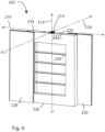
- the modular wall 202 and the modular wall system 200 will be explained hereinafter with reference to FIGS. 3 and 4 .
- the modular wall 202 has a length 'L I' and a height 'H1' in a plane 212 of the modular wall 202.
- the modular wall 202 defines a vertical axis 214 along the height 'H1' and a first axis 216 along the length 'L1'.
- the modular wall 202 further defines a second axis 218 perpendicular to each of the vertical axis 214 and the first axis 216.
- the modular wall 202 is disposed adjacent to the sidewall 112 and parallel to the first axis 216. Further, the modular wall 202 is also disposed in between the sidewalls 110 and 114.
- the modular wall 202 includes a supporting member 220 having a first side 222 and a second side 224.
- the supporting member 220 may include multiple shelves 226 that are disposed on the first side 222 of the supporting member 220. Further, the first side 222 of the supporting member 220 may face the sidewall 112. In another embodiment, the shelves 226 may be disposed on the second side 224 of the supporting member 220. Alternatively, the supporting member 220 may further include shelves 226 that are disposed on both the first side 222 and second side 224 of the supporting member 220.
- the supporting member 220 may or may not include other types of shelves 226 or components.
- the modular wall 202 also includes a pair of wings 228 and 230 slidably attached to the supporting member 220.
- the wings 228 and 230 are attached to the first side 222 of the supporting member 220.
- the wings 228 and 230 may act as doors for the shelves 226 of the supporting member 220.
- the wings 228 and 230 may be attached to the second side 224 of the supporting member 220.
- the modular wall 202 includes a supporting member 220 disposed in the plane 212.
- the modular wall 202 further includes a pair of wings 228 and 230 operatively coupled to the supporting member 220.
- the wings 228 and 230 may be slidably attached to the supporting member 220 so as to slide along the plane 212.
- each of the wings 228 and 230 may be coupled to the supporting member 220 via an elongate member (not shown) having an I-shape.
- one side of the elongate member may be attached to the corresponding wings 228, 230 and the other side of the elongate member may be attached to the supporting member 220 via a track disposed in the supporting member 220. As such, the wings 228 and 230 may slide along the track.
- the modular wall 202 may include a receiving member (not shown) attached to the supporting member 220 adjacent to a top end 234 and a bottom end 236 of the modular wall 202 thereof.
- each of the wings 228 and 230 may include a track member 238 corresponding to each of the receiving member.
- the receiving member may slide inside the track member 238 to enable the wings 228 and 230 to slide parallel to the first axis 216.
- the supporting member 220 may define a recess in each of the sides of the supporting member 220, as illustrated in FIG. 4 .
- the wings 228 and 230 may be configured to be slidably received in the corresponding recesses, at least partially. With such an implementation, both the first and second sides 222 and 224 of the modular wall 202 remain accessible with the wings 228 and 230 either in open position or closed position. As such, the shelves or other features may be suitably enabled on any of the sides 222, and/or 224 of the modular wall 202.
- the wings 228 and 230 may be rotatably coupled to the supporting member 220 so as to fold out from the supporting member 220.
- the wings 228 and 230 may be coupled to the supporting member 220 by hinges.
- the wings 228 and 230 may have a concertina arrangement. It may also be contemplated to use other mechanisms to accomplish the coupling between the wings 228, 230 and the supporting member 220.
- one of the wings 228 or 230 may be attached to the first side 222 and the other of the wing 228 or 230 may be attached to the second side 224, as illustrated in FIG. 5 .
- the modular wall 202 may also include multiple pairs of wings 228, 230 that may be attached to each of the first and second sides 222 and 224 of the supporting member 220.
- Each of the wings 228, 230 is configured to move towards an open position and a closed position. Further a combined length 'L1' of the modular wall 202 having the wings 228, 230 in the open position may be substantially equal to the distance between the sidewalls 110, 114 between which the modular wall 202 is disposed. As such, the wings 228, 230 may move towards the sidewalls 110, 114 respectively while moving towards the open position. In the illustrated embodiment, the wings 228, 230 may contact the sidewalls 110, 114 respectively in the open position.
- the modular wall 202 may include one or more secondary wings (not shown) coupled to each of the wings 228 and 230.
- the secondary wings may either be slidably or rotatably coupled to the corresponding wings 228 and 230. As such, to obtain the open position, each of the secondary wings and the wings 228, 230 may have to be unfolded.
- the modular wall 202 is disposed parallel to the first axis 216. In other embodiments, the modular wall 202 may be suitably disposed at an angle with the first axis 216. In an example, the modular wall 202 may be disposed at an angle of 90 degrees to the first axis 216 based on the shape of the modular room 108.
- the modular wall 202 may be disposed in various other configurations and shapes of the rooms.
- a size, a shape and a configuration of the supporting member 220 and/or the wings 228, 230 may vary to suit the requirements of the application. Accordingly, the wings 228, 230 in the open position may substantially contact the corresponding sidewalls 110, 112, 114, 116.
- each of the wings 228, 230 may further include an additional wing slidably coupled thereto. As such, in the open position of both the additional wings and the wings 228, 230, the additional wings may contact the corresponding sidewalls 110, 112, 114, 116.
- the modular wall 202 is configured to move parallel to the second axis 218.
- the modular wall 202 may also be configured to rotate about the vertical axis 214.
- the modular wall 202 may be configured to rotate about the first axis 216. As such, the modular wall 202 may be flipped against the ceiling 118.
- the modular wall system 200 also includes a support structure 300.
- the modular wall 202 may be movably coupled to the support structure 300.
- the support structure 300 is configured to be coupled to the ceiling 118 of the modular room 108.
- the support structure 300 includes a rail member 302 disposed parallel to the second axis 218 and coupled to the ceiling 118.
- the rail member 302 may be coupled to the ceiling 118 via an overhanging structure 304.
- the overhanging structure 304 may be coupled to the ceiling 118.
- the overhanging structure 304 may include multiple bars coupled to each other via fasteners. Alternatively, at least some of the bars of the overhanging structure 304 may be welded to each other.
- the support structure 300 also includes an elongate member 306 having a first end 308 and a second end 310. As shown, the elongate member 306 has an I-shape. The first end 308 may be slidably received in the rail member 302.
- the support structure 300 also includes a first flange member 312 that is coupled to the first end 308 of the elongate member 306.
- the support structure 300 further includes a second flange member 314 coupled to the first flange member 312.
- Each of the first and second flange members 312 and 314 may have a plate configuration. Further, the second flange member 314 is coupled to the top end 234 of the modular wall 202. With such an implementation, the modular wall 202 may be moved parallel to the rail member 302.
- first and second flange members 312 and 314 may be accomplished by using any suitable methods such as, but not limited to fasteners, welding and the like. Further, the first flange member 312 and the second flange member 314 may be coupled to the second end 310 of the elongate member 306 and the top end 234 of the modular wall 202 respectively, by any suitable methods such as, but not limited to fasteners such as, threaded screws or bolts, studs, welding and the like.
- the support structure 300 may include multiple rail members 302 disposed parallel to each other.
- the support structure 300 may also include multiple elongate members 306 that may be slidably received in the corresponding rail members 302. Further, the elongate members 306 may be coupled to the top end 234 of the modular wall 202 at different locations.
- the elongate member 306 may include a rotatable member (not shown) disposed between the first end 308 and the second end 310.
- the rotatable member (not shown) may be a circular member rotatably coupled to the elongate member 306 adjacent to the second end 310.
- the modular wall 202 may rotate about the vertical axis 214.
- the support structure may also include floor tracks (not shown) attached to the bottom end 236 of the modular wall 202.
- the floor tracks may include any of the rails, wheels and the like that can enable the modular wall 202 to translate and/or rotate about the vertical axis 214.
- the modular wall 202 is disposed against the sidewall 112 and further, the wings 228 and 230 are in the closed position.
- FIG. 7 the modular wall 202 being moved to a moved position is illustrated.
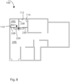
- FIG. 8 the modular room 200 divided into two rooms 240 and 242 by the modular wall 202 is illustrated.
- the modular wall 202 may be at a distance from the sidewall 112. The distance may be chosen based on a ratio of sizes that may be desired for the rooms 240 and 242.
- the modular wall 202 may be moved parallel to the second axis 218 in the moved position.
- the modular wall 202 with the wings 228 and 230 in the open position is illustrated.
- Each of the wings 228 and 230 may be slid parallel to the first axis 216 in the open position.
- the wings 228 and 230 may include a handle (not shown) disposed thereon. Accordingly, the wings 228 and 230 may be at least partially moved towards the open position using the respective handles. Further as shown, in the open position the wings 228 and 230 may substantially contact the corresponding sidewalls 110 and 114, respectively.
- the modular room 108 includes two rooms 240 and 242. As can be seen from FIG. 8 , the room 242 formed with the modular wall 202, and the sidewalls 110, 112, 114 have a closed configuration.
- the modular room 108 may include more than one modular wall 202. Accordingly, the modular room 108 may be divided into more than two rooms.
- the modular room 108 may include an additional wall disposed against one of the sidewalls 110 or 114. Referring to FIG. 8 , the additional wall may be moved parallel to the first axis 216. Further, the corresponding wings 228, 230 of the additional modular wall may be slid to the open position so as to divide the room 242 into two other rooms. As such, the modular room 108 with two modular walls 202 may be divided into three rooms.
- any of the rooms may be converted into at least two rooms.
- the second side 224 of the supporting member 220 may be disposed against one of the sidewalls 110, 112, 114, 116 and the wings 228, 230 may be disposed in the closed position.
- various components such as, a television, decorative items or the like may be disposed on the first side 222 of the supporting member 220.
- the modular wall 202 may form part of the modular room 108 without interfering with other components of the modular room 108.
- the modular wall 202 may be moved parallel to the second axis 218 to a certain position and the wings 228, 230 may be moved to the open position to obtain two rooms.
- furniture in the modular room 108 may be arranged such that the movement of the modular 202 may be achieved without moving the furniture.
- the wings 228, 230 of the modular wall 202 in the open position are configured to contact the corresponding sidewalls 110, 114 of the modular room 108. As such, at least one closed room may be obtained.
- the use of drywall 202 in dividing the modular room 108 into multiple rooms may render various properties to the divided room such as acoustic properties, insulation, aesthetics and the like.
- the terms “comprises,” “comprising,” “includes,” “including,” “has,” “having” or any other variation thereof, are intended to cover a non-exclusive inclusion.
- a method, article, or apparatus that comprises a list of features is not necessarily limited only to those features but may include other features not expressly listed or inherent to such method, article, or apparatus.
- “or” refers to an inclusive-or and not to an exclusive-or. For example, a condition A or B is satisfied by any one of the following: A is true (or present) and B is false (or not present), A is false (or not present) and B is true (or present), and both A and B are true (or present).
Landscapes
- Engineering & Computer Science (AREA)
- Architecture (AREA)
- Civil Engineering (AREA)
- Structural Engineering (AREA)
- Electromagnetism (AREA)
- Physics & Mathematics (AREA)
- Building Environments (AREA)
- Residential Or Office Buildings (AREA)
- Tents Or Canopies (AREA)
- Specific Sealing Or Ventilating Devices For Doors And Windows (AREA)
- Wing Frames And Configurations (AREA)
- Holders For Apparel And Elements Relating To Apparel (AREA)
- Financial Or Insurance-Related Operations Such As Payment And Settlement (AREA)
Claims (20)
- Modulares Wandsystem (200) für einen Raum mit einer Vielzahl von Seitenwänden (110, 112, 114, 116) und einer Decke (118), wobei das modulare Wandsystem (220) umfasst:eine Trägerstruktur (300), die zum Koppeln mit der Decke (118) des Raums eingerichtet ist; undeine modulare Wand (202), die beweglich mit der Trägerstruktur gekoppelt ist,wobei die modulare Wand (202) eine vertikale Achse (214) entlang einer Höhe davon, eine erste Achse (216) entlang einer Länge davon und eine zu jeweils der vertikalen Achse (214) und der ersten Achse (216) senkrechte zweite Achse (218) definiert, wobei die modulare Wand (202) so eingerichtet ist, dass sie sich parallel zu der zweiten Achse (218) bewegt,wobei die Trägerstruktur (300) umfasst:ein Schienenelement (302), das parallel zur zweiten Achse (218) angeordnet und mit der Decke (118) koppelbar ist;ein längliches Element (306) mit I-Form mit einem ersten Ende (308) und einem zweiten Ende (310), wobei das erste Ende (308) verschiebbar im Schienenelement (302) angeordnet ist;ein erstes Flanschelement (312), das mit dem ersten Ende (308) des länglichen Elements (306) gekoppelt ist; undein zweites Flanschelement (314), das über das längliche Element (306) mit dem ersten Flanschelement (312) gekoppelt ist und mit einem oberen Ende der modularen Wand (202) gekoppelt ist;wobei die modulare Wand (202) umfasst:ein Trägerelement (220); undein Paar Flügel (228, 230), das funktionell mit dem Trägerelement (220) gekoppelt ist, wobei das Trägerelement (220) und das Paar Flügel (228, 230) jeweils umfassen:einen Rahmen (204); undeine oder mehrere am Rahmen (204) befestigte Gipsplatten (208),wobei jeder der Flügel (228, 230) so eingerichtet ist, dass er sich in eine offene Position und eine geschlossene Position bewegt, wobei das Paar Flügel (228, 230) so eingerichtet ist, dass es sich in der offenen Position in Richtung einer entsprechenden Seitenwand (110, 114) der Vielzahl von Seitenwänden bewegt,und wobei die modulare Wand (202) so eingerichtet ist, dass sie zwischen einer Position, in der das Trägerelement (220) an einer Seitenwand angeordnet ist, und einer Position, in der es von der Seitenwand beabstandet ist, wodurch der Raum unterteilt wird, bewegt werden kann.
- Modulares Wandsystem (200) nach Anspruch 1, wobei jeder der Flügel (228, 230) so eingerichtet ist, dass er entlang einer Ebene des Trägerelements (220) gleitet.
- Modulares Wandsystem (200) nach Anspruch 1, wobei jeder der Flügel (228, 230) durch Scharniere schwenkbar mit dem Trägerelement (220) verbunden ist.
- Modulares Wandsystem (200) nach Anspruch 1, wobei jeder der Flügel (228, 230) eine Ziehharmonika-Anordnung aufweist.
- Modulares Wandsystem (200) nach Anspruch 1, wobei jeder der Flügel (228, 230) ferner einen beweglich daran angebrachten sekundären Flügel umfasst.
- Modulares Wandsystem (200) nach Anspruch 1, wobei das Trägerelement (220) eine Vielzahl von Regalen (226) umfasst.
- Modulares Wandsystem (200) nach Anspruch 1, wobei jedes von den Trägerelementen (220) und dem Paar Flügel (228, 230) ein Dämmelement umfasst, das zwischen dem Rahmen (204) und einer oder mehreren Gipsplatten (208) angeordnet ist.
- Modulares Wandsystem (200) nach Anspruch 1, wobei der Rahmen (204) aus mindestens einem von Metall, Holz oder Kunststoff gefertigt ist.
- Modulares Wandsystem (200) nach Anspruch 1, wobei das Trägerelement (220) und das Paar Flügel (228, 230) verstärkt sind.
- Modulares Wandsystem (200) nach Anspruch 1, wobei die Gipsplatte (208) ein Polymerbindemittel und eine Vielzahl von Fasern umfasst.
- Modulares Wandsystem (200) nach Anspruch 10, wobei das Polymerbindemittel entweder Stärke oder ein synthetisches Material umfasst.
- Modulares Wandsystem (200) nach Anspruch 10, wobei das Polymerbindemittel und die Vielzahl von Fasern zusammen mehr als 1 Gew.-% der modularen Wand ausmachen.
- Modulares Wandsystem (200) nach Anspruch 10, wobei eines von dem Polymerbindemittel und der Vielzahl von Fasern, mehr als 1 Gew.-% der modularen Wand ausmachen.
- Modulares Wandsystem (200) nach Anspruch 1, umfassend mindestens eines aus MDF, Sperrholz, Glas, Metall, Zement, Faserzement oder Kunststoffplatte.
- Modulares Wandsystem (200) nach Anspruch 1, wobei die modulare Wand (202) ferner eingerichtet ist, um sich um mindestens eine von der vertikalen Achse (214) und der ersten Achse (216) zu drehen.
- Modulares Wandsystem (200) nach Anspruch 1, wobei die Trägerstruktur (300) Bodenbahnen umfasst, die an einem unteren Ende der modularen Wand (202) angeordnet sind.
- Modulares Wandsystem (200) nach Anspruch 1, wobei die Bodenbahnen entweder Schienen oder Räder sind.
- Modulares Wandsystem (200) nach Anspruch 1, wobei das Paar Flügel (228, 230) in der offenen Position so eingerichtet ist, dass es die entsprechende Seitenwand der Vielzahl von Seitenwänden berührt.
- Modularer Raum (108), umfassend:eine Vielzahl von Seitenwänden (110, 112, 114, 116);mindestens ein modulares Wandsystem (200) nach Anspruch 1, wobei die Vielzahl von Seitenwänden, die mindestens eine modulare Wand (202) in der bewegten Position und das Paar Flügel (228, 230) in der geöffneten Position so eingerichtet sind, dass sie innerhalb des modularen Raums (108) mindestens zwei Räume bilden;eine Decke (118), die auf der Vielzahl von Seitenwänden angeordnet ist; undwobei die Trägerstruktur (300) mit der Decke (118) gekoppelt ist, wobei die mindestens eine modulare Wand (202) parallel zur zweiten Achse (218) verschiebbar mit der Trägerstruktur (300) gekoppelt ist.
- Modularer Raum (108) nach Anspruch 19, wobei mindestens einer der beiden unterteilten Räume ein geschlossener Raum ist.
Applications Claiming Priority (2)
| Application Number | Priority Date | Filing Date | Title |
|---|---|---|---|
| IN201641023767 | 2016-07-12 | ||
| PCT/IN2017/050272 WO2018011820A1 (en) | 2016-07-12 | 2017-07-05 | Modular room |
Publications (4)
| Publication Number | Publication Date |
|---|---|
| EP3485113A1 EP3485113A1 (de) | 2019-05-22 |
| EP3485113A4 EP3485113A4 (de) | 2020-03-18 |
| EP3485113B1 true EP3485113B1 (de) | 2024-09-11 |
| EP3485113C0 EP3485113C0 (de) | 2024-09-11 |
Family
ID=60952883
Family Applications (1)
| Application Number | Title | Priority Date | Filing Date |
|---|---|---|---|
| EP17827138.3A Active EP3485113B1 (de) | 2016-07-12 | 2017-07-05 | Modularer raum |
Country Status (10)
| Country | Link |
|---|---|
| US (1) | US10822797B2 (de) |
| EP (1) | EP3485113B1 (de) |
| JP (1) | JP7074693B2 (de) |
| KR (1) | KR102238387B1 (de) |
| CN (1) | CN109477340B (de) |
| MY (1) | MY193908A (de) |
| PH (1) | PH12018502671B1 (de) |
| SG (1) | SG11201811235SA (de) |
| WO (1) | WO2018011820A1 (de) |
| ZA (1) | ZA201900601B (de) |
Families Citing this family (7)
| Publication number | Priority date | Publication date | Assignee | Title |
|---|---|---|---|---|
| JP7122100B2 (ja) * | 2017-10-31 | 2022-08-19 | 株式会社オカムラ | 移動間仕切装置 |
| US10577788B1 (en) * | 2019-01-11 | 2020-03-03 | Impact Urban, LLC | Reconfigurable living space |
| JP7486744B2 (ja) | 2020-09-18 | 2024-05-20 | 大成建設株式会社 | 可動型仕切り壁 |
| KR102448910B1 (ko) * | 2021-06-10 | 2022-09-30 | 한국건설기술연구원 | 가변형 스마트 월 시스템 |
| KR102456558B1 (ko) * | 2021-06-22 | 2022-10-19 | 한국건설기술연구원 | 공간 가변형 스마트 월 제어방법 |
| CN113958082A (zh) * | 2021-11-11 | 2022-01-21 | 高明 | 可循环内装系统 |
| WO2025262174A1 (de) * | 2024-06-18 | 2025-12-26 | Häfele SE & Co KG | Wandsystem und raumanordnung |
Family Cites Families (31)
| Publication number | Priority date | Publication date | Assignee | Title |
|---|---|---|---|---|
| US3107400A (en) | 1961-11-03 | 1963-10-22 | Hugh Stubbins And Associates I | Movable wall partition |
| DE1554206A1 (de) * | 1965-09-07 | 1970-03-05 | Feisel Helwig Jakob | Verschiebbare,doppelseitig zugaengliche Schranktrennwand zur Veraenderung der Wohnraumflaeche |
| JPS5523063A (en) * | 1978-08-08 | 1980-02-19 | Nittetsu Kinzoku Kogyo Kk | Sliding door core material made from gypsum as main raw material and its manufacture |
| JPS56150285A (en) * | 1980-04-18 | 1981-11-20 | Nittetsu Kinzoku Kogyo Kk | Soundproof paper door device |
| JPS57190890U (de) * | 1981-05-29 | 1982-12-03 | ||
| JPS5942212U (ja) * | 1982-09-13 | 1984-03-19 | ナショナル住宅産業株式会社 | 間仕切装置 |
| US5090171A (en) * | 1989-08-01 | 1992-02-25 | Komatsu Wall Industry Co., Ltd. | Movable partitioning panel |
| US5167575A (en) * | 1989-08-23 | 1992-12-01 | Macdonald Ross P | Clean room including an internal partition system |
| JPH0483040A (ja) * | 1990-07-24 | 1992-03-17 | Tategu Sogo Shosha Futaba:Kk | 建築物 |
| JPH04135509A (ja) * | 1990-09-27 | 1992-05-11 | Takenaka Komuten Co Ltd | 間仕切り兼用収納ユニット |
| US5152332A (en) * | 1991-02-26 | 1992-10-06 | Modernfold, Inc. | Movable wall system |
| DE10250054B4 (de) * | 2002-10-25 | 2005-10-27 | Dorma Gmbh + Co. Kg | Schiebewand |
| US20050257437A1 (en) * | 2004-04-19 | 2005-11-24 | Robert Juten | Method, system and article of manufacture for a modular room |
| US20060248826A1 (en) * | 2005-05-05 | 2006-11-09 | Owens N D | Soffit assembly for moveable wall system and removal tool therefor |
| JP4517948B2 (ja) | 2005-06-09 | 2010-08-04 | 鹿島建設株式会社 | 移動式防音システム及び移動式防音塀 |
| DE102006007511A1 (de) * | 2005-06-14 | 2006-12-21 | Wilfried Boldt | Schienengeführtes Mobilwandelement |
| JP5103093B2 (ja) * | 2007-08-24 | 2012-12-19 | 株式会社岡村製作所 | 移動間仕切装置における間仕切パネル |
| US20090250176A1 (en) * | 2008-04-08 | 2009-10-08 | Versare Solutions, Inc. | Expandable portable wall partition |
| FR2933438B1 (fr) * | 2008-07-03 | 2010-09-10 | Saint Gobain | Paroi coulissante |
| TWI362442B (en) * | 2009-04-15 | 2012-04-21 | Univ Nat Taiwan Science Tech | Movable office screen system |
| US8443866B2 (en) * | 2010-07-16 | 2013-05-21 | Won-Door Corporation | Methods, apparatuses, and systems for movable partitions |
| CN202012275U (zh) * | 2011-01-30 | 2011-10-19 | 孔锤彬 | 一种折叠拉门和使用这种折叠拉门的淋浴房 |
| US9249567B2 (en) * | 2011-07-26 | 2016-02-02 | Haworth, Inc. | Reusable architectural wall |
| DE202011052302U1 (de) * | 2011-12-14 | 2012-02-28 | Josef Kestel | Raumteiler in Form eines Schiebeelementes |
| US20140013668A1 (en) * | 2012-07-12 | 2014-01-16 | Asi Technologies, Inc. | Sliding Door Cover Rail |
| GB2519889B (en) * | 2012-08-24 | 2020-10-21 | Allsteel Inc | Modular wall system |
| FI125283B (fi) * | 2012-11-01 | 2015-08-14 | Lumon Invest Oy | Paneelijärjestelmä |
| US9222255B2 (en) * | 2013-08-01 | 2015-12-29 | Urbaneer LLC | Apparatus and method for reconfigurable space |
| US10385600B2 (en) * | 2016-05-11 | 2019-08-20 | Contour Closures, Inc. | Horizontal garage door assembly |
| KR101734034B1 (ko) | 2017-01-02 | 2017-05-10 | 케이에스토스템 주식회사 | 폴딩 도어용 하부 레일 |
| US10407960B2 (en) * | 2017-02-03 | 2019-09-10 | Assa Abloy Entrance Systems Ab | Automatically actuated door lock system |
-
2017
- 2017-07-05 SG SG11201811235SA patent/SG11201811235SA/en unknown
- 2017-07-05 CN CN201780043210.0A patent/CN109477340B/zh active Active
- 2017-07-05 PH PH1/2018/502671A patent/PH12018502671B1/en unknown
- 2017-07-05 MY MYPI2018002951A patent/MY193908A/en unknown
- 2017-07-05 EP EP17827138.3A patent/EP3485113B1/de active Active
- 2017-07-05 KR KR1020197000727A patent/KR102238387B1/ko not_active Expired - Fee Related
- 2017-07-05 JP JP2018568278A patent/JP7074693B2/ja active Active
- 2017-07-05 US US16/316,619 patent/US10822797B2/en active Active
- 2017-07-05 WO PCT/IN2017/050272 patent/WO2018011820A1/en not_active Ceased
-
2019
- 2019-01-29 ZA ZA2019/00601A patent/ZA201900601B/en unknown
Also Published As
| Publication number | Publication date |
|---|---|
| SG11201811235SA (en) | 2019-01-30 |
| KR102238387B1 (ko) | 2021-04-09 |
| CN109477340A (zh) | 2019-03-15 |
| KR20190026752A (ko) | 2019-03-13 |
| US20190292778A1 (en) | 2019-09-26 |
| PH12018502671B1 (en) | 2022-11-18 |
| WO2018011820A1 (en) | 2018-01-18 |
| JP2019520497A (ja) | 2019-07-18 |
| MY193908A (en) | 2022-10-31 |
| EP3485113C0 (de) | 2024-09-11 |
| JP7074693B2 (ja) | 2022-05-24 |
| US10822797B2 (en) | 2020-11-03 |
| EP3485113A4 (de) | 2020-03-18 |
| CA3028366A1 (en) | 2018-01-18 |
| EP3485113A1 (de) | 2019-05-22 |
| PH12018502671A1 (en) | 2019-10-21 |
| ZA201900601B (en) | 2022-03-30 |
| CN109477340B (zh) | 2021-05-25 |
Similar Documents
| Publication | Publication Date | Title |
|---|---|---|
| EP3485113B1 (de) | Modularer raum | |
| US6761004B2 (en) | Reconfigurable room partitioning system | |
| US4356672A (en) | Partitioning system | |
| US10273676B2 (en) | Architectural structures having an expandable frame | |
| GB2527343A (en) | Expandable storage structure | |
| AU2015101579A4 (en) | Lightweight High Tech Door | |
| CA3028366C (en) | Movable modular wall, movable modular wall system and modular room therefrom | |
| EP2894270A1 (de) | Ineinandergreifendes modulares Element für Baukonstruktionen und Möbel | |
| EP1953395A1 (de) | Verfahren zum Zusammenbau von Sandwichplatten in einem Winkelverhältnis zueinander und mit diesem Verfahren hergestellte Strukturen | |
| HK40003259B (en) | Modular room | |
| HK40003259A (en) | Modular room | |
| US20130112356A1 (en) | Temporary Partition System and Components for the Same | |
| US8997425B2 (en) | Wall panel system and method | |
| GB2480096A (en) | Temporary partitioning system comprising, in use, vertically elongate interlocking components | |
| US3608989A (en) | Cabinet or cabinet panel, from prefabricated parts | |
| JP2017186762A (ja) | 建物 | |
| KR200500217Y1 (ko) | 조립식 모듈 수납장 | |
| US7845502B1 (en) | Tapering-depth shelving unit for use behind doors | |
| JP6256823B2 (ja) | 収納装置 | |
| JP5922345B2 (ja) | 面格子壁構造および木造建築物 | |
| EP1982619A1 (de) | Modulares Elementsystem zur Verwendung bei der Herstellung von Kleiderschränken und Küchenmöbeln | |
| WO2023159256A1 (en) | A building element | |
| EP2180106A1 (de) | Montagesystem für Paneelwände | |
| EP3584379A1 (de) | Verbessertes modulares gebäude und segmente | |
| KR0174352B1 (ko) | 분해결합이 용이한 칸막이판넬과 그 판넬을 이용하는 케비넷 시스템 |
Legal Events
| Date | Code | Title | Description |
|---|---|---|---|
| STAA | Information on the status of an ep patent application or granted ep patent |
Free format text: STATUS: THE INTERNATIONAL PUBLICATION HAS BEEN MADE |
|
| PUAI | Public reference made under article 153(3) epc to a published international application that has entered the european phase |
Free format text: ORIGINAL CODE: 0009012 |
|
| STAA | Information on the status of an ep patent application or granted ep patent |
Free format text: STATUS: REQUEST FOR EXAMINATION WAS MADE |
|
| 17P | Request for examination filed |
Effective date: 20190212 |
|
| AK | Designated contracting states |
Kind code of ref document: A1 Designated state(s): AL AT BE BG CH CY CZ DE DK EE ES FI FR GB GR HR HU IE IS IT LI LT LU LV MC MK MT NL NO PL PT RO RS SE SI SK SM TR |
|
| AX | Request for extension of the european patent |
Extension state: BA ME |
|
| DAV | Request for validation of the european patent (deleted) | ||
| DAX | Request for extension of the european patent (deleted) | ||
| REG | Reference to a national code |
Ref country code: DE Free format text: PREVIOUS MAIN CLASS: E04H0001000000 Ref country code: DE Ref legal event code: R079 Ref document number: 602017084827 Country of ref document: DE Free format text: PREVIOUS MAIN CLASS: E04H0001000000 Ipc: E04B0002820000 |
|
| A4 | Supplementary search report drawn up and despatched |
Effective date: 20200217 |
|
| RIC1 | Information provided on ipc code assigned before grant |
Ipc: E04B 2/82 20060101AFI20200211BHEP |
|
| RAP1 | Party data changed (applicant data changed or rights of an application transferred) |
Owner name: SAINT-GOBAIN PLACO |
|
| STAA | Information on the status of an ep patent application or granted ep patent |
Free format text: STATUS: EXAMINATION IS IN PROGRESS |
|
| 17Q | First examination report despatched |
Effective date: 20221012 |
|
| GRAP | Despatch of communication of intention to grant a patent |
Free format text: ORIGINAL CODE: EPIDOSNIGR1 |
|
| STAA | Information on the status of an ep patent application or granted ep patent |
Free format text: STATUS: GRANT OF PATENT IS INTENDED |
|
| INTG | Intention to grant announced |
Effective date: 20240422 |
|
| GRAS | Grant fee paid |
Free format text: ORIGINAL CODE: EPIDOSNIGR3 |
|
| GRAA | (expected) grant |
Free format text: ORIGINAL CODE: 0009210 |
|
| STAA | Information on the status of an ep patent application or granted ep patent |
Free format text: STATUS: THE PATENT HAS BEEN GRANTED |
|
| AK | Designated contracting states |
Kind code of ref document: B1 Designated state(s): AL AT BE BG CH CY CZ DE DK EE ES FI FR GB GR HR HU IE IS IT LI LT LU LV MC MK MT NL NO PL PT RO RS SE SI SK SM TR |
|
| REG | Reference to a national code |
Ref country code: GB Ref legal event code: FG4D |
|
| REG | Reference to a national code |
Ref country code: CH Ref legal event code: EP |
|
| REG | Reference to a national code |
Ref country code: DE Ref legal event code: R096 Ref document number: 602017084827 Country of ref document: DE |
|
| REG | Reference to a national code |
Ref country code: IE Ref legal event code: FG4D |
|
| U01 | Request for unitary effect filed |
Effective date: 20240923 |
|
| U07 | Unitary effect registered |
Designated state(s): AT BE BG DE DK EE FI FR IT LT LU LV MT NL PT RO SE SI Effective date: 20241015 |
|
| U1N | Appointed representative for the unitary patent procedure changed after the registration of the unitary effect |
Representative=s name: SAINT-GOBAIN RECHERCHE; FR |
|
| PG25 | Lapsed in a contracting state [announced via postgrant information from national office to epo] |
Ref country code: NO Free format text: LAPSE BECAUSE OF FAILURE TO SUBMIT A TRANSLATION OF THE DESCRIPTION OR TO PAY THE FEE WITHIN THE PRESCRIBED TIME-LIMIT Effective date: 20241211 |
|
| PG25 | Lapsed in a contracting state [announced via postgrant information from national office to epo] |
Ref country code: GR Free format text: LAPSE BECAUSE OF FAILURE TO SUBMIT A TRANSLATION OF THE DESCRIPTION OR TO PAY THE FEE WITHIN THE PRESCRIBED TIME-LIMIT Effective date: 20241212 |
|
| PG25 | Lapsed in a contracting state [announced via postgrant information from national office to epo] |
Ref country code: HR Free format text: LAPSE BECAUSE OF FAILURE TO SUBMIT A TRANSLATION OF THE DESCRIPTION OR TO PAY THE FEE WITHIN THE PRESCRIBED TIME-LIMIT Effective date: 20240911 |
|
| PG25 | Lapsed in a contracting state [announced via postgrant information from national office to epo] |
Ref country code: ES Free format text: LAPSE BECAUSE OF FAILURE TO SUBMIT A TRANSLATION OF THE DESCRIPTION OR TO PAY THE FEE WITHIN THE PRESCRIBED TIME-LIMIT Effective date: 20240911 Ref country code: RS Free format text: LAPSE BECAUSE OF FAILURE TO SUBMIT A TRANSLATION OF THE DESCRIPTION OR TO PAY THE FEE WITHIN THE PRESCRIBED TIME-LIMIT Effective date: 20241211 |
|
| PG25 | Lapsed in a contracting state [announced via postgrant information from national office to epo] |
Ref country code: RS Free format text: LAPSE BECAUSE OF FAILURE TO SUBMIT A TRANSLATION OF THE DESCRIPTION OR TO PAY THE FEE WITHIN THE PRESCRIBED TIME-LIMIT Effective date: 20241211 Ref country code: NO Free format text: LAPSE BECAUSE OF FAILURE TO SUBMIT A TRANSLATION OF THE DESCRIPTION OR TO PAY THE FEE WITHIN THE PRESCRIBED TIME-LIMIT Effective date: 20241211 Ref country code: HR Free format text: LAPSE BECAUSE OF FAILURE TO SUBMIT A TRANSLATION OF THE DESCRIPTION OR TO PAY THE FEE WITHIN THE PRESCRIBED TIME-LIMIT Effective date: 20240911 Ref country code: GR Free format text: LAPSE BECAUSE OF FAILURE TO SUBMIT A TRANSLATION OF THE DESCRIPTION OR TO PAY THE FEE WITHIN THE PRESCRIBED TIME-LIMIT Effective date: 20241212 Ref country code: ES Free format text: LAPSE BECAUSE OF FAILURE TO SUBMIT A TRANSLATION OF THE DESCRIPTION OR TO PAY THE FEE WITHIN THE PRESCRIBED TIME-LIMIT Effective date: 20240911 |
|
| PG25 | Lapsed in a contracting state [announced via postgrant information from national office to epo] |
Ref country code: IS Free format text: LAPSE BECAUSE OF FAILURE TO SUBMIT A TRANSLATION OF THE DESCRIPTION OR TO PAY THE FEE WITHIN THE PRESCRIBED TIME-LIMIT Effective date: 20250111 |
|
| PG25 | Lapsed in a contracting state [announced via postgrant information from national office to epo] |
Ref country code: SM Free format text: LAPSE BECAUSE OF FAILURE TO SUBMIT A TRANSLATION OF THE DESCRIPTION OR TO PAY THE FEE WITHIN THE PRESCRIBED TIME-LIMIT Effective date: 20240911 |
|
| PG25 | Lapsed in a contracting state [announced via postgrant information from national office to epo] |
Ref country code: PL Free format text: LAPSE BECAUSE OF FAILURE TO SUBMIT A TRANSLATION OF THE DESCRIPTION OR TO PAY THE FEE WITHIN THE PRESCRIBED TIME-LIMIT Effective date: 20240911 Ref country code: CZ Free format text: LAPSE BECAUSE OF FAILURE TO SUBMIT A TRANSLATION OF THE DESCRIPTION OR TO PAY THE FEE WITHIN THE PRESCRIBED TIME-LIMIT Effective date: 20240911 |
|
| PG25 | Lapsed in a contracting state [announced via postgrant information from national office to epo] |
Ref country code: SK Free format text: LAPSE BECAUSE OF FAILURE TO SUBMIT A TRANSLATION OF THE DESCRIPTION OR TO PAY THE FEE WITHIN THE PRESCRIBED TIME-LIMIT Effective date: 20240911 |
|
| PGFP | Annual fee paid to national office [announced via postgrant information from national office to epo] |
Ref country code: GB Payment date: 20250529 Year of fee payment: 9 |
|
| U20 | Renewal fee for the european patent with unitary effect paid |
Year of fee payment: 9 Effective date: 20250606 |
|
| PLBE | No opposition filed within time limit |
Free format text: ORIGINAL CODE: 0009261 |
|
| STAA | Information on the status of an ep patent application or granted ep patent |
Free format text: STATUS: NO OPPOSITION FILED WITHIN TIME LIMIT |
|
| 26N | No opposition filed |
Effective date: 20250612 |
|
| PGFP | Annual fee paid to national office [announced via postgrant information from national office to epo] |
Ref country code: CH Payment date: 20250801 Year of fee payment: 9 |