EP3485781B2 - Appareil d'aspiration pourvu de module de fonction - Google Patents
Appareil d'aspiration pourvu de module de fonction Download PDFInfo
- Publication number
- EP3485781B2 EP3485781B2 EP18215339.5A EP18215339A EP3485781B2 EP 3485781 B2 EP3485781 B2 EP 3485781B2 EP 18215339 A EP18215339 A EP 18215339A EP 3485781 B2 EP3485781 B2 EP 3485781B2
- Authority
- EP
- European Patent Office
- Prior art keywords
- suction device
- suction
- function module
- module
- electric
- Prior art date
- Legal status (The legal status is an assumption and is not a legal conclusion. Google has not performed a legal analysis and makes no representation as to the accuracy of the status listed.)
- Active
Links
Images


Classifications
-
- A—HUMAN NECESSITIES
- A47—FURNITURE; DOMESTIC ARTICLES OR APPLIANCES; COFFEE MILLS; SPICE MILLS; SUCTION CLEANERS IN GENERAL
- A47L—DOMESTIC WASHING OR CLEANING; SUCTION CLEANERS IN GENERAL
- A47L9/00—Details or accessories of suction cleaners, e.g. mechanical means for controlling the suction or for effecting pulsating action; Storing devices specially adapted to suction cleaners or parts thereof; Carrying-vehicles specially adapted for suction cleaners
-
- A—HUMAN NECESSITIES
- A47—FURNITURE; DOMESTIC ARTICLES OR APPLIANCES; COFFEE MILLS; SPICE MILLS; SUCTION CLEANERS IN GENERAL
- A47L—DOMESTIC WASHING OR CLEANING; SUCTION CLEANERS IN GENERAL
- A47L7/00—Suction cleaners adapted for additional purposes; Tables with suction openings for cleaning purposes; Containers for cleaning articles by suction; Suction cleaners adapted to cleaning of brushes; Suction cleaners adapted to taking-up liquids
- A47L7/0085—Suction cleaners adapted for additional purposes; Tables with suction openings for cleaning purposes; Containers for cleaning articles by suction; Suction cleaners adapted to cleaning of brushes; Suction cleaners adapted to taking-up liquids adapted for special purposes not related to cleaning
-
- A—HUMAN NECESSITIES
- A47—FURNITURE; DOMESTIC ARTICLES OR APPLIANCES; COFFEE MILLS; SPICE MILLS; SUCTION CLEANERS IN GENERAL
- A47L—DOMESTIC WASHING OR CLEANING; SUCTION CLEANERS IN GENERAL
- A47L7/00—Suction cleaners adapted for additional purposes; Tables with suction openings for cleaning purposes; Containers for cleaning articles by suction; Suction cleaners adapted to cleaning of brushes; Suction cleaners adapted to taking-up liquids
- A47L7/0095—Suction cleaners or attachments adapted to collect dust or waste from power tools
-
- A—HUMAN NECESSITIES
- A47—FURNITURE; DOMESTIC ARTICLES OR APPLIANCES; COFFEE MILLS; SPICE MILLS; SUCTION CLEANERS IN GENERAL
- A47L—DOMESTIC WASHING OR CLEANING; SUCTION CLEANERS IN GENERAL
- A47L9/00—Details or accessories of suction cleaners, e.g. mechanical means for controlling the suction or for effecting pulsating action; Storing devices specially adapted to suction cleaners or parts thereof; Carrying-vehicles specially adapted for suction cleaners
- A47L9/28—Installation of the electric equipment, e.g. adaptation or attachment to the suction cleaner; Controlling suction cleaners by electric means
- A47L9/2805—Parameters or conditions being sensed
- A47L9/2821—Pressure, vacuum level or airflow
-
- A—HUMAN NECESSITIES
- A47—FURNITURE; DOMESTIC ARTICLES OR APPLIANCES; COFFEE MILLS; SPICE MILLS; SUCTION CLEANERS IN GENERAL
- A47L—DOMESTIC WASHING OR CLEANING; SUCTION CLEANERS IN GENERAL
- A47L9/00—Details or accessories of suction cleaners, e.g. mechanical means for controlling the suction or for effecting pulsating action; Storing devices specially adapted to suction cleaners or parts thereof; Carrying-vehicles specially adapted for suction cleaners
- A47L9/28—Installation of the electric equipment, e.g. adaptation or attachment to the suction cleaner; Controlling suction cleaners by electric means
- A47L9/2805—Parameters or conditions being sensed
- A47L9/2831—Motor parameters, e.g. motor load or speed
-
- A—HUMAN NECESSITIES
- A47—FURNITURE; DOMESTIC ARTICLES OR APPLIANCES; COFFEE MILLS; SPICE MILLS; SUCTION CLEANERS IN GENERAL
- A47L—DOMESTIC WASHING OR CLEANING; SUCTION CLEANERS IN GENERAL
- A47L9/00—Details or accessories of suction cleaners, e.g. mechanical means for controlling the suction or for effecting pulsating action; Storing devices specially adapted to suction cleaners or parts thereof; Carrying-vehicles specially adapted for suction cleaners
- A47L9/28—Installation of the electric equipment, e.g. adaptation or attachment to the suction cleaner; Controlling suction cleaners by electric means
- A47L9/2836—Installation of the electric equipment, e.g. adaptation or attachment to the suction cleaner; Controlling suction cleaners by electric means characterised by the parts which are controlled
- A47L9/2842—Suction motors or blowers
-
- A—HUMAN NECESSITIES
- A47—FURNITURE; DOMESTIC ARTICLES OR APPLIANCES; COFFEE MILLS; SPICE MILLS; SUCTION CLEANERS IN GENERAL
- A47L—DOMESTIC WASHING OR CLEANING; SUCTION CLEANERS IN GENERAL
- A47L9/00—Details or accessories of suction cleaners, e.g. mechanical means for controlling the suction or for effecting pulsating action; Storing devices specially adapted to suction cleaners or parts thereof; Carrying-vehicles specially adapted for suction cleaners
- A47L9/28—Installation of the electric equipment, e.g. adaptation or attachment to the suction cleaner; Controlling suction cleaners by electric means
- A47L9/2857—User input or output elements for control, e.g. buttons, switches or displays
-
- A—HUMAN NECESSITIES
- A47—FURNITURE; DOMESTIC ARTICLES OR APPLIANCES; COFFEE MILLS; SPICE MILLS; SUCTION CLEANERS IN GENERAL
- A47L—DOMESTIC WASHING OR CLEANING; SUCTION CLEANERS IN GENERAL
- A47L9/00—Details or accessories of suction cleaners, e.g. mechanical means for controlling the suction or for effecting pulsating action; Storing devices specially adapted to suction cleaners or parts thereof; Carrying-vehicles specially adapted for suction cleaners
- A47L9/28—Installation of the electric equipment, e.g. adaptation or attachment to the suction cleaner; Controlling suction cleaners by electric means
- A47L9/2894—Details related to signal transmission in suction cleaners
-
- H—ELECTRICITY
- H01—ELECTRIC ELEMENTS
- H01R—ELECTRICALLY-CONDUCTIVE CONNECTIONS; STRUCTURAL ASSOCIATIONS OF A PLURALITY OF MUTUALLY-INSULATED ELECTRICAL CONNECTING ELEMENTS; COUPLING DEVICES; CURRENT COLLECTORS
- H01R13/00—Details of coupling devices of the kinds covered by groups H01R12/70 or H01R24/00 - H01R33/00
- H01R13/66—Structural association with built-in electrical component
-
- H—ELECTRICITY
- H01—ELECTRIC ELEMENTS
- H01R—ELECTRICALLY-CONDUCTIVE CONNECTIONS; STRUCTURAL ASSOCIATIONS OF A PLURALITY OF MUTUALLY-INSULATED ELECTRICAL CONNECTING ELEMENTS; COUPLING DEVICES; CURRENT COLLECTORS
- H01R24/00—Two-part coupling devices, or either of their cooperating parts, characterised by their overall structure
- H01R24/76—Two-part coupling devices, or either of their cooperating parts, characterised by their overall structure with sockets, clips or analogous contacts and secured to apparatus or structure, e.g. to a wall
-
- H—ELECTRICITY
- H01—ELECTRIC ELEMENTS
- H01R—ELECTRICALLY-CONDUCTIVE CONNECTIONS; STRUCTURAL ASSOCIATIONS OF A PLURALITY OF MUTUALLY-INSULATED ELECTRICAL CONNECTING ELEMENTS; COUPLING DEVICES; CURRENT COLLECTORS
- H01R27/00—Coupling parts adapted for co-operation with two or more dissimilar counterparts
- H01R27/02—Coupling parts adapted for co-operation with two or more dissimilar counterparts for simultaneous co-operation with two or more dissimilar counterparts
-
- H—ELECTRICITY
- H01—ELECTRIC ELEMENTS
- H01R—ELECTRICALLY-CONDUCTIVE CONNECTIONS; STRUCTURAL ASSOCIATIONS OF A PLURALITY OF MUTUALLY-INSULATED ELECTRICAL CONNECTING ELEMENTS; COUPLING DEVICES; CURRENT COLLECTORS
- H01R9/00—Structural associations of a plurality of mutually-insulated electrical connecting elements, e.g. terminal strips or terminal blocks; Terminals or binding posts mounted upon a base or in a case; Bases therefor
- H01R9/22—Bases, e.g. strip, block, panel
- H01R9/24—Terminal blocks
- H01R9/2491—Terminal blocks structurally associated with plugs or sockets
-
- H—ELECTRICITY
- H01—ELECTRIC ELEMENTS
- H01R—ELECTRICALLY-CONDUCTIVE CONNECTIONS; STRUCTURAL ASSOCIATIONS OF A PLURALITY OF MUTUALLY-INSULATED ELECTRICAL CONNECTING ELEMENTS; COUPLING DEVICES; CURRENT COLLECTORS
- H01R13/00—Details of coupling devices of the kinds covered by groups H01R12/70 or H01R24/00 - H01R33/00
- H01R13/46—Bases; Cases
- H01R13/52—Dustproof, splashproof, drip-proof, waterproof, or flameproof cases
- H01R13/5213—Covers
-
- H—ELECTRICITY
- H01—ELECTRIC ELEMENTS
- H01R—ELECTRICALLY-CONDUCTIVE CONNECTIONS; STRUCTURAL ASSOCIATIONS OF A PLURALITY OF MUTUALLY-INSULATED ELECTRICAL CONNECTING ELEMENTS; COUPLING DEVICES; CURRENT COLLECTORS
- H01R2103/00—Two poles
Definitions
- the invention relates to a suction device for separating particles from a suction flow, with a suction motor for generating the suction flow and with a suction housing having a control wall for operating the suction device according to the preamble of claim 1.
- Such a suction device is, for example EP 1 955 637 A2 known.
- Such a control wall usually has an on and off switch for switching the suction device on and off. Furthermore, further controls, for example for adjusting the speed of the suction motor, can be provided at this point. Suction devices used in the workshop often have a socket for connecting an electrical tool. However, the scope of functions of the suction device is fixed.
- a basic idea of the invention is that the functional module can be replaced as required. It is therefore possible to use different functional modules with different requirements for the suction device. It goes without saying that several module holders can also be present on a suction device according to the invention.
- control wall is expediently an external wall simply because of its accessibility.
- the functional module it would be conceivable for the functional module to be placed entirely on the vacuum cleaner housing in the assembled state, i.e. not to penetrate into the vacuum cleaner housing.
- the module holder has a receiving space in which the at least one functional module is completely or partially accommodated in the assembled state.
- the recording room is advantageously accessible from the outside.
- the receiving space is a receiving chamber or a receiving shaft.
- the receiving space is so deep that a front side of the at least one functional module does not protrude, or only protrudes insignificantly, from a part of the control wall surrounding the receiving space.
- the penetration depth of the functional module therefore essentially corresponds to a depth or height of the functional module.
- the functional module does not protrude in front of the vacuum cleaner housing, which is visually appealing and provides mechanical protection for the functional module.
- a sealing arrangement that protects the functional module, the module receptacle or the electrical connection arrangement as well as corresponding contacts of the functional module from environmental influences is also advantageous.
- at least one seal can be provided on the connections of the connection arrangement. It is preferred if a seal is arranged on the outer circumference of the functional module and/or on an inner circumference of the module receptacle. The seal is preferably designed so that no dirt can penetrate into the receiving space.
- the electrical connection arrangement preferably has supply contacts for supplying electrical energy to an electrical consumer that can be connected to the suction device.
- the consumer is, for example, a power tool.
- the supply contacts can have a switchable switching supply contact that can be switched on and off by a switch on the suction device.
- This switch of the suction device can be a separate switch specifically assigned to the switching supply contact or, in a preferred embodiment of the invention, a "main switch", advantageously a switch that is provided for switching the suction motor.
- the supply contact is a permanent current contact, which is, for example, permanently connected to a power supply connection of the suction device, with which it can be connected to a power supply network. If the suction device is operated using an accumulator, the permanent current contact is permanently connected to the accumulator.
- an automatic supply contact is useful, to which a current sensor is assigned. If current flows via the automatic supply contact, this current flow is detected by the current sensor.
- One or more power supply connections in the respective supply module can be supplied with electrical energy via the supply contacts of the suction device, to which an electrical consumer, for example an electric tool, can in turn be connected.
- the functional module can be with one or several of the aforementioned supply contacts, for example the switching supply contact, the continuous current contact and the automatic supply contact, can be connected by means of a selector switch. It goes without saying that the selector switch can only allow the selection of two of the three aforementioned contacts.
- the functional module is reconfigurable in such a way that the power supply contact can be connected to at least two of the three of the aforementioned variants - switching supply contact, continuous current contact or automatic supply contact - by, for example, replugging the power connections of the functional model.
- the electrical connection arrangement of the suction device expediently also has suction device signal contacts and/or a wireless internal interface for communicating data signals and/or control signals to the functional module or from the respective functional module.
- the signal contacts are expediently potential-free, for which purpose a relay or the like can be provided.
- connection of the functional module to the suction device is expediently carried out without tools.
- Locking means for example locking hooks
- the connecting means can include, for example, one or more screws.
- a variant of the invention can provide that the functional module can deliberately only be attached to or detached from the suction device using a tool. This can, for example, represent improved theft protection or be indicated for electrical reasons, namely that the supply contacts of the suction device are not openly accessible. It goes without saying that for connecting means that can only be actuated with tools, locking means or the like can also be used, but these can advantageously only be brought into a release or release position for removing the functional module with a suitable tool.
- the functional module according to the invention provides an electrical, optical or acoustic function or any combinations thereof.
- the functional module can be, for example, a switching module.
- Display modules are also useful.
- the functional module expediently has suction device signal contacts that can connect to the module signal contacts, for example to communicate data signals or control signals.
- the data signals are expediently bus data signals.
- the functional module has an electrical switch for switching on or off the suction motor of the suction device.
- this switch is a signal switch, i.e. it outputs a switching signal for switching the suction motor on or off at a main switch arranged in the suction device.
- the switching signal can be transmitted to the suction device potential-free.
- the switching signal expediently has a lower potential than the main switch of the suction device, with which the suction motor can be switched on and off.
- the functional module can be a compressed air module.
- the functional module has, for example, a compressed air connection arrangement for connecting a compressed air tool.
- the compressed air connection arrangement expediently includes compressed air connections for looping through a compressed air line supplying the compressed air tool. At least one of the compressed air connections is expediently provided with a quick coupling and/or a counterpart for quick couplings.
- the compressed air functional module expediently includes a compressed air sensor for detecting a compressed air stream that flows through the functional module.
- the compressed air sensor contains, for example, a spring-loaded sensor body, in particular a float, which can be actuated when compressed air is actuated or when the compressed air flows through and closes a switch, preferably a reed contact.
- the float can be magnetic, for example. It goes without saying that the compressed air sensor can also be a pressure switch that can be actuated by pressure.
- the functional module has a current sensor for detecting a current flowing through the functional module.
- a potential-free switching contact is also useful. If, for example, a consumer is connected to the aforementioned power supply connection and this is switched on, i.e. for example an electric tool is switched on, the current sensor or the switching contact reports this to the suction device, which in turn then activates the suction motor.
- the respective sensor for example the compressed air sensor, the current sensor or the switching contact, are advantageously connected to the module signal contacts for transmitting data signals and control signals.
- the functional module can also include a bus coupler for connection to a data bus of the suction device.
- the functional module includes, for example, data contacts for connecting a data device to a data bus of the suction device and/or the functional module. This makes it possible, for example, to diagnose, program or calibrate the suction device and/or functional module.
- the data contacts are expediently connected to the module contacts for connection to the data bus of the suction device.
- the invention provides that the functional module has a wireless external interface for wireless communication with the functional module and/or the suction device.
- the functional module has a wireless external interface for wireless communication with the functional module and/or the suction device.
- the functional module can have optical or acoustic output means for outputting data, for example diagnostic data of the suction device, music or the like.
- data for example diagnostic data of the suction device, music or the like.
- a variant of the invention provides that the functional module has compensation for noise emissions from the suction device.
- the functional module can also have a radio receiver and/or data reading means.
- the data reading means are suitable, for example, for outputting music data stored in MP3 format or another music data format.
- a functional module according to the invention can also be a master-slave module, with the help of which a further suction device can be connected to the suction device according to the invention.
- the two suction devices can be switched on and off at the same time so that their suction power is available simultaneously.
- the current sensor in the functional module of the other suction device to which the aforementioned suction device is connected detects the current flow to the newly switched on suction device and, as a result, also switches on the suction device having the functional module according to the invention. This then forms a slave suction device.
- the suction device is a transportable, for example rollable and/or portable, suction device, according to the invention a workshop vacuum.
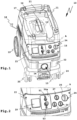
- a suction motor 12 is arranged to generate a suction stream 13, which can be sucked into the suction cup housing 11 via a suction inlet 14.
- a hose not shown, can be connected to the suction inlet 14.
- a receptacle 17 for receiving the suction hose and/or a connecting cable 18 with which the suction device 10 can be connected to an electrical supply network.
- the suction device 10 is a transportable suction device, on the underside of which rollers 19, 20 are arranged.
- the front castors 20 are swivel casters. Furthermore, the suction device 10 can be gripped on a carrying handle 21 on the top 16.
- a control wall 23 with control elements 24 for operating the suction device 10 extends between a front wall 22 having the suction inlet 14 and the top side 16.
- the control wall 23 is expediently inclined at an angle so that the control elements 24 can be easily operated from diagonally above at the front.
- the operating elements 24 include a switch 25, which forms a main switch, so to speak.
- the suction motor 12 can be switched on and off using the switch 25.
- an automatic mode can be set in which the suction motor 12 always runs when a connected consumer receives electrical power via the suction device 10, which will be explained later.
- a suction power or speed switch 26 With the help of a suction power or speed switch 26, the power of the suction motor 12 can be adjusted.
- An adjustment switch 27 enables electrical adjustment of the suction device 10 to a suction hose connected to a respective suction inlet 14.
- a cleaning function of the suction device 10 can be switched on and/or parameterized using a cleaning switch 28.
- a socket 29 permanently installed on the suction device 10 enables an electrical energy consumer to be plugged in. The socket 29 is electrically connected to the connection cable 18.
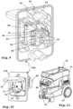
- the suction device 10 optionally provides additional functions that the operator can select as required: On the control wall 23 there is a module holder 30 for selectively holding functional modules 50a, 50d, which provide electrical, optical and acoustic functions.
- the module receptacle 30 is designed in the form of a receptacle shaft that is closed. Circumferential walls 32, 33 extend from the control wall 23 in the direction of the interior of the vacuum cleaner housing 11 to a bottom 31 of the module holder 30. This prevents dirt from penetrating through the module receptacle 30 into the interior of the vacuum cleaner housing 11.
- a sealing arrangement 35 with a seal 36 is provided.
- the seal 36 is, for example, an O-ring which is arranged on an edge region 34 of the receiving space 37 approximately between the operating wall 23 and the peripheral walls 32, 33.
- the module holder 30 can also be covered by a cover plate 38, the contour of which is the same as the front walls 51a - 51d ( Figure 11 ).
- the receiving space 37 forms a plug-in receptacle for receiving the functional modules 50a - 50d, which can therefore be easily inserted into the module receptacle 30.
- the functional modules 50a - 50d can be detachably connected to the suction cup housing 11.
- the receiving space 37 designed as a plug-in receptacle already forms a component of connecting means 52 with which the functional module 50a - 50d can be detachably connected to the suction cup housing 11.
- the connecting means 52 include guide ribs 39 which protrude in front of the peripheral walls 32, 33 and guide the respective functional module 50a - 50d and support it in the assembled state.
- the connecting means 52 also include screws 53 which are inserted through screw domes 65 of the functional modules 50a - 50d, which are aligned with screw receptacles 40 of the module receptacle 30 when the respective functional module 50a - 50d is mounted on the vacuum cleaner 10.
- the receiving space 37 has a depth that is sufficient so that the front wall 51a - 51d is essentially aligned with the control wall 23 when the respective functional module 50a - 50d is attached to the vacuum cleaner 11.
- the connection arrangement 41 includes supply contacts 42 with a permanent current contact 43, which is always connected to the connecting cable 18, so that, for example, a potential of 230 V is present at the continuous current contact 43 when the connecting cable 18 is connected to an electrical supply network, not shown.
- the supply contacts 42 include a switching supply contact 44, which then has a power supply potential when the switch 25 switches on the suction motor 12, and an automatic supply contact 45, to which a current sensor 46 for detecting a current flow via the automatic supply contact 45 is assigned.
- supply contacts 42a (protective conductor / PE) and 42b (ground / M) are components of the supply contacts 42.
- a data or signaling connection between the suction device and the functional module 50a - 50d is possible via suction device signal contacts 47.
- data contacts 48 are connected to a data bus of the suction device 10.
- Switching contacts 49 enable potential-free signaling of an on and off signal for switching the suction motor 12 on and off when the switch 25 is set to "automatic".
- the electrical connection arrangement 51 enables a multitude of possibilities for a wide variety of functional modules, of which the functional modules 50a - 50d are explained below as an example:
- the functional module 50a is a compressed air module for connecting a compressed air tool.
- the functional module 50a has a compressed air connection arrangement 54 with compressed air connections 55a, 55b, to which a compressed air hose can be connected.
- the compressed air connection 55a includes a quick coupling, while the compressed air connection 55b forms, so to speak, a counterpart for a quick coupling, which is arranged on a compressed air hose, not shown.
- a compressed air connection can therefore be looped through the functional module 50a via the connection arrangement 54, with a compressed air path in the functional module 50a leading via a compressed air sensor 56 to detect a compressed air flow.
- the compressed air sensor 56 actuates a switch 57 which is connected to module signal contacts 58.
- the module signal contacts 58 are electrically connected to the suction device signal contacts 47. This creates, for example, an electrical connection between the switch 57 and the switching contacts 49, so that when the compressed air tool (not shown) connected to the compressed air connection arrangement 54 is actuated, the switch 57 bridges the two switching contacts 49, which results in switching on of the suction motor 12 leads.
- the electronic or electrical components of the functional module 50a are advantageously housed in a housing 59 in a protected manner.
- the housing 59 is expediently dimensioned so that it is guided on the guide ribs 39.
- the functional module 50b is used for potential-free switching of the suction motor 12.
- a plug connector 60 for inserting a plug is arranged on its front wall 51b.
- the plug connector which in the present case is designed as a socket, can be closed by means of a cover 61 and can therefore be protected from environmental influences.
- contacts 62a, 62b of the connector 60 are connected to contacts 58b of the module signal contacts 58, so that an electrical connection between the module signal contacts 58b and the suction device signal contacts 47 on the suction device side can be established by inserting the functional module 50b into the module receptacle 30.
- a data connection for connection to a data bus of the suction device 10 would also be possible.
- contacts 62a, 62c are connected to module signal contacts 58a by means of lines 63, 64, which come into connection with the data contacts 48 on the suction cup when the functional module 50b is inserted.
- a computer is connected to the contacts 62a, 62c.
- guide projections 66 in the manner of lateral guide wings are provided on the screw domes 65 of the functional module 50b.
- the functional module 50c is used to entertain a user of the suction device 10. It has a radio receiver 67 and data reading means 68 for reading music data.
- a memory card SD card, MMC card or the like
- the data reading means 68 reads out can be inserted into a slot 72 of the data reading means 68 arranged on a front wall 51c.
- music data is stored on the card in MP3 format.
- a loudspeaker 69 i.e. an acoustic output means, is used to output music and speech from the radio receiver 67 and the data reading means.
- Optical output means 71 for example an LCD display, are also expediently present, for example to display the currently tuned station.
- the display 70 can also be used to output diagnostic data of the suction device 10, for example to display operating hours, the current suction power or the like.
- the loudspeaker 69 can also be used for diagnostic messages, for example to emit a warning tone when the filter arrangement 15 is filled to maximum capacity.
- the functional module 50d has an electrical power supply connection 73 arranged on the front wall 51d for connecting an electrical consumer, for example an electric tool.
- the power supply connection 73 includes a socket 74, preferably a protective contact socket, which can be closed by means of a cover 75.
- the lid 75 is pivotable with respect to the front wall 51d.
- Contacts 76, 77 and 78 of the socket 74 are connected to contacts 79, 80 and 81 of a plug connector 82 via lines 83.
- the plug connector 82 is used to establish electrical connections to the supply contacts 42 of the electrical connection arrangement 41 of the suction device 10.
- the contact 79 establishes a connection to the supply contact 42a, thus establishing a protective conductor connection, while the contact 80 forms a ground connection with the other supply contact 42b.
- the contact 81 is connected to the permanent current contact 43 when the functional module 50d is plugged in. You could also arrange the contact 81 at any time at one of the contact locations 84 or 85 in order to establish a connection to the switching supply contact 44 on the vacuum device side or the automatic supply contact 45 when the functional module 50d is inserted.
- the functional module 50d can therefore be reconfigured at any time.
- wiring with free lines 83 also has the advantage that different contact locations, for example the contact locations 84 or 85, can be connected to the power supply contact 78 of the socket 74 following a common parts principle.
- the term electrical connection arrangement between a suction device according to the invention and an associated functional module expediently provides electrical contacts. Electrical contact surfaces are advantageous at least for electrical power supply of the respective functional module by the suction device.
- the electrical connection arrangement can also be designed to be wireless. If the functional module then has a local energy supply, for example an accumulator, electrical line connections or contact connections between the suction device and the functional module are not even necessary.
- the functional module 50b for wireless communication with the suction device 10 could have a radio module 86 for implementing a wireless internal interface 87, which is arranged on the suction device 10 Radio module 88 communicates wirelessly, which represents a wireless internal interface 89.
- the module signal contacts 58 are then not required, at most for electrical power supply of the functional module 50b.
Landscapes
- Engineering & Computer Science (AREA)
- Mechanical Engineering (AREA)
- Electric Vacuum Cleaner (AREA)
- Hooks, Suction Cups, And Attachment By Adhesive Means (AREA)
- External Artificial Organs (AREA)
- Manipulator (AREA)
Claims (14)
- Appareil d'aspiration transportable pour trier des particules provenant d'un flux d'aspiration (13), avec un moteur à aspiration (12) pour générer le flux d'aspiration (13) et avec un boîtier d'aspirateur (11) présentant une paroi d'utilisation (23) pour utiliser l'appareil d'aspiration (10), dans lequel le moteur d'aspiration (12) est disposé à l'intérieur du boîtier d'aspirateur (11) et le flux d'aspiration (13) peut être aspiré dans le boîtier d'aspirateur (11) par l'intermédiaire d'une entrée d'aspiration (14), dans lequel un ensemble filtrant (15) pour trier des particules provenant du flux d'aspiration (13) se trouve à l'intérieur du boîtier d'aspirateur (11), dans lequel au moins un logement de module (30) pour loger au moins un module fonctionnel (50a - 50d) offrant une fonction électrique et/ou optique et/ou acoustique est disposé au niveau de la paroi d'utilisation (23), dans lequel un ensemble de raccordement (41) électrique pour un raccordement électrique de l'au moins un module fonctionnel (50a - 50d) à l'appareil d'aspiration (10) est disposé au niveau du logement de module (30), et dans lequel l'au moins un module fonctionnel (50a - 50d) peut être relié de manière amovible au boîtier d'aspirateur (11) au moyen de moyens de liaison (52), caractérisé en ce que l'appareil d'aspiration (10) présente un module fonctionnel (50a - 50d), qui peut être disposé au niveau du logement de module (30) de l'appareil d'aspiration (10) et peut être relié de manière mécanique à l'appareil d'aspiration (10) au moyen de moyens de liaison (52) et de manière électrique à un ensemble de raccordement (41) électrique et offre une fonction électrique et/ou optique et/ou acoustique, et que le module fonctionnel (50a - 50d) présente une interface externe sans fil pour la communication sans fil avec le module fonctionnel (50a - 50d) et/ou l'appareil d'aspiration (10) de sorte qu'il est possible d'activer et de désactiver l'appareil d'aspiration (10) et de régler sa puissance d'aspiration au moyen d'une commande à distance, dans lequel l'appareil d'aspiration (10) est un aspirateur d'atelier.
- Appareil d'aspiration selon la revendication 1, caractérisé en ce que le logement de module (30) présente un espace de logement (37), dans lequel l'au moins un module fonctionnel (50a - 50d) est logé au moins en partie dans l'état monté au niveau de l'appareil d'aspiration (10).
- Appareil d'aspiration selon la revendication 1 ou 2, caractérisé en ce que l'espace de logement (37) est si profond qu'un côté frontal de l'au moins un module fonctionnel (50a - 50d), dans l'état monté au niveau de l'appareil d'aspiration (10), ne fait pas saillie ou fait saillie seulement de manière minime d'une partie, entourant l'espace de logement (37), de la paroi d'utilisation (23).
- Appareil d'aspiration selon l'une quelconque des revendications précédentes, caractérisé en ce qu'un ensemble d'étanchéité (35) pour la protection contre des influences extérieures est disposé entre le boîtier d'aspirateur (11) et l'au moins un module fonctionnel (50a - 50d), dans lequel l'ensemble d'étanchéité (35) comprend de manière opportune un joint d'étanchéité (36) disposé entre le logement de module (30) et l'au moins un module fonctionnel (50a - 50d), en particulier entre une périphérie de l'au moins un module fonctionnel (50a - 50d) et la paroi d'utilisation (23) ou une paroi périphérique du logement de module (30) et/ou de manière avantageuse un joint d'étanchéité disposé au niveau de l'ensemble de raccordement (41) électrique.
- Appareil d'aspiration selon l'une quelconque des revendications précédentes, caractérisé en ce que l'ensemble de raccordement (41) électrique présente des contacts d'alimentation (42) pour l'alimentation en énergie électrique d'un consommateur électrique pouvant être raccordé à l'appareil d'aspiration (10), en particulier d'un outil électrique.
- Appareil d'aspiration selon la revendication 5, caractérisé en ce que les contacts d'alimentation (42) comprennent un contact d'alimentation de commutation (44) pouvant être commuté par un commutateur (25), en particulier pour commuter le moteur à aspiration (12), de l'appareil d'aspiration (10) et/ou un contact à courant continu (43) relié à une entrée de courant de l'appareil d'aspiration (10) et/ou un contact d'alimentation automatique (45), dans lequel un capteur de courant (46) pour détecter un flux de courant circulant vers le contact d'alimentation automatique (45) est associé au contact d'alimentation automatique (45).
- Appareil d'aspiration selon l'une quelconque des revendications précédentes, caractérisé en ce que l'ensemble de raccordement (41) électrique comprend des contacts de signaux d'appareil d'aspiration (47) et/ou une interface interne (89) sans fil pour la communication de signaux de données, en particulier de signaux de données de bus, et/ou de signaux de commande à l'au moins un module fonctionnel (50a - 50d) ou depuis l'au moins un module fonctionnel (50a - 50d).
- Appareil d'aspiration selon l'une quelconque des revendications précédentes, caractérisé en ce que les moyens de liaison (52) comprennent au moins une vis (53) et/ou des moyens d'enclenchement et/ou un moyen de liaison par emboîtement, en particulier en ce que le module fonctionnel (50a - 50c) est configuré en tant qu'un module d'emboîtement pouvant être emboîté au niveau de ou dans l'appareil d'aspiration (10) et/ou le logement de module (30) est configuré en tant qu'un logement par emboîtement.
- Appareil d'aspiration selon l'une quelconque des revendications précédentes, caractérisé en ce que le module fonctionnel (50a - 50d) comprend des contacts de signaux de module (58) prévus pour être reliés aux contacts de signaux d'appareil d'aspiration (47) de l'appareil d'aspiration (10) et/ou une interface interne (87) sans fil pour la communication de signaux de données, en particulier de signaux de données de bus, et/ou de signaux de commande à l'appareil d'aspiration (10) ou provenant de l'appareil d'aspiration (10), et/ou que le module fonctionnel présente un commutateur (57) électrique pour activer et/ou désactiver le moteur à aspiration (12) de l'appareil d'aspiration (10).
- Appareil d'aspiration selon l'une quelconque des revendications précédentes, caractérisé en ce que le module fonctionnel (50a - 50d) présente un ensemble de raccordement à air comprimé (54) pour raccorder un outil à air comprimé, et/ou qu'il présente un raccordement d'alimentation en courant électrique (73) pour l'alimentation en énergie électrique d'un consommateur électrique pouvant être raccordé à l'appareil d'aspiration (10), en particulier d'un outil électrique.
- Appareil d'aspiration selon la revendication 10, caractérisé en ce que le raccordement d'alimentation en courant (73) est relié ou peut être relié, en particulier au moyen d'un commutateur de sélection, dans l'état monté au niveau de l'appareil d'aspiration (10), à un contact d'alimentation de commutation (44) pouvant être commuté par un commutateur (25) de l'appareil d'aspiration (10) ou à un contact à courant continu (43) relié à une entrée de courant de l'appareil d'aspiration (10) ou à un contact d'alimentation automatique (45), dans lequel un capteur de courant (46) disposé dans le boîtier d'aspirateur (11), pour détecter un flux de courant circulant vers le contact d'alimentation automatique (45) est associé au contact d'alimentation automatique (45).
- Appareil d'aspiration selon l'une quelconque des revendications précédentes, caractérisé en ce que le module fonctionnel (50a - 50d) présente un capteur d'air comprimé (56) pour détecter un courant d'air comprimé traversant le module fonctionnel (50a - 50d) et/ou un capteur de courant pour détecter un flux de courant traversant le module fonctionnel (50a - 50d) et/ou un contact de commutation sans potentiel, et/ou qu'il présente des contacts de données pour raccorder un appareil de données à un bus de données de l'appareil d'aspiration (10) et/ou du module fonctionnel (50a - 50d).
- Appareil d'aspiration selon l'une quelconque des revendications précédentes, caractérisé en ce que le module fonctionnel (50a - 50d) présente des moyens d'envoi (69, 71) optiques et/ou acoustiques pour envoyer des données, en particulier des données de diagnostic de l'appareil d'aspiration (10), ou de la musique ou des bruits de compensation compensant une émission acoustique en particulier de l'appareil d'aspiration (10).
- Appareil d'aspiration selon l'une quelconque des revendications précédentes, caractérisé en ce que le module fonctionnel (50a - 50d) présente un récepteur radio (67) et/ou des moyens de lecture de données (68) pour des données musicales mémorisées en particulier au format MP3.
Applications Claiming Priority (2)
| Application Number | Priority Date | Filing Date | Title |
|---|---|---|---|
| DE102009015642.9A DE102009015642B4 (de) | 2009-03-21 | 2009-03-21 | Sauggerät mit Funktionsmodul |
| EP10002155.9A EP2229857B1 (fr) | 2009-03-21 | 2010-03-03 | Dispositif d'aspiration doté d'un module de fonctionnement |
Related Parent Applications (2)
| Application Number | Title | Priority Date | Filing Date |
|---|---|---|---|
| EP10002155.9A Division EP2229857B1 (fr) | 2009-03-21 | 2010-03-03 | Dispositif d'aspiration doté d'un module de fonctionnement |
| EP10002155.9A Previously-Filed-Application EP2229857B1 (fr) | 2009-03-21 | 2010-03-03 | Dispositif d'aspiration doté d'un module de fonctionnement |
Publications (4)
| Publication Number | Publication Date |
|---|---|
| EP3485781A2 EP3485781A2 (fr) | 2019-05-22 |
| EP3485781A3 EP3485781A3 (fr) | 2019-07-10 |
| EP3485781B1 EP3485781B1 (fr) | 2020-08-19 |
| EP3485781B2 true EP3485781B2 (fr) | 2023-10-04 |
Family
ID=42244077
Family Applications (2)
| Application Number | Title | Priority Date | Filing Date |
|---|---|---|---|
| EP18215339.5A Active EP3485781B2 (fr) | 2009-03-21 | 2010-03-03 | Appareil d'aspiration pourvu de module de fonction |
| EP10002155.9A Active EP2229857B1 (fr) | 2009-03-21 | 2010-03-03 | Dispositif d'aspiration doté d'un module de fonctionnement |
Family Applications After (1)
| Application Number | Title | Priority Date | Filing Date |
|---|---|---|---|
| EP10002155.9A Active EP2229857B1 (fr) | 2009-03-21 | 2010-03-03 | Dispositif d'aspiration doté d'un module de fonctionnement |
Country Status (3)
| Country | Link |
|---|---|
| EP (2) | EP3485781B2 (fr) |
| DE (1) | DE102009015642B4 (fr) |
| DK (2) | DK2229857T3 (fr) |
Families Citing this family (21)
| Publication number | Priority date | Publication date | Assignee | Title |
|---|---|---|---|---|
| DE102010040336A1 (de) * | 2010-09-07 | 2012-03-08 | Alfred Kärcher Gmbh & Co. Kg | Vorrichtung und Verfahren zum Erfassen einer Betriebszustandsänderung eines Elektrowerkzeuges sowie Staubsauger |
| DE202011003605U1 (de) | 2011-03-05 | 2011-05-05 | Festool Gmbh | Sauggerät mit einer Steckdose |
| DE102012003073A1 (de) | 2012-02-17 | 2013-08-22 | Festool Group Gmbh & Co. Kg | Sauggerät mit einer Sauggerät-Kommunikationseinrichtung |
| DE102012003077A1 (de) | 2012-02-17 | 2013-08-22 | Festool Group Gmbh & Co. Kg | Identifikationsverfahren für ein Sauggerät und eine Hand-Werkzeugmaschine |
| DE102012003076A1 (de) | 2012-02-17 | 2013-08-22 | Festool Group Gmbh & Co. Kg | Sauggerät mit einem Sauggerät-Sender und Extern-Kommunikationseinrichtung dafür |
| EP4398451A3 (fr) | 2012-02-17 | 2024-10-02 | Festool GmbH | Appareil d'aspiration doté d'un dispositif de charge |
| CN204833259U (zh) | 2012-07-17 | 2015-12-02 | 米沃奇电动工具公司 | 电动工具及电动工具系统 |
| EP3028810B2 (fr) | 2013-08-02 | 2023-12-27 | Makita Corporation | Collecteur de poussière |
| CN104986014B (zh) * | 2015-07-06 | 2017-01-04 | 江苏埃萨云派环境科技有限公司 | 车载高能离子空气净化装置 |
| WO2017190784A1 (fr) * | 2016-05-04 | 2017-11-09 | Alfred Kärcher Gmbh & Co. Kg | Système de traitement du sol |
| DK3320822T3 (da) | 2016-11-07 | 2019-06-24 | Festool Gmbh | Sugeindretning med en tilslutningsindretning |
| DE202017101501U1 (de) | 2017-03-15 | 2017-04-03 | Häring Metallbau GmbH & Co. KG | Pneumatische Steuerung und Vorrichtung zur Absaugung von durch ein pneumatisches Handgerät verursachten Staub |
| DE102017205072A1 (de) * | 2017-03-27 | 2018-09-27 | Robert Bosch Gmbh | Sauggerät mit Steckmodul |
| WO2019009938A1 (fr) | 2017-07-05 | 2019-01-10 | Milwaukee Electric Tool Corporation | Adaptateurs pour communication entre des outils électriques |
| DE102017219303A1 (de) * | 2017-10-27 | 2019-05-02 | Robert Bosch Gmbh | Erweiterungsmodul für ein kabelgebundenes Arbeitsgerät |
| US11011053B2 (en) | 2018-07-31 | 2021-05-18 | Tti (Macao Commercial Offshore) Limited | Systems and methods for remote power tool device control |
| EP4247228A4 (fr) | 2020-11-19 | 2025-08-27 | Milwaukee Electric Tool Corp | Dépoussiéreur portatif |
| US12273937B2 (en) | 2021-02-16 | 2025-04-08 | Milwaukee Electric Tool Corporation | Communication between a wireless dust extractor and a power tool |
| WO2026041808A1 (fr) | 2024-08-23 | 2026-02-26 | Festool Gmbh | Appareil d'aspiration doté d'un compartiment de rangement pour tuyau d'aspiration |
| DE102024124229A1 (de) * | 2024-08-23 | 2026-02-26 | Festool Gmbh | Sauggerät mit einem Steckverbindereinsatz |
| CN120999333B (zh) * | 2025-10-21 | 2026-02-27 | 温州力士盾电器有限公司 | 具有吸盘结构的排插 |
Citations (4)
| Publication number | Priority date | Publication date | Assignee | Title |
|---|---|---|---|---|
| EP1391263A1 (fr) † | 2002-08-21 | 2004-02-25 | Hitachi Koki Co., Ltd. | Collecteur de poussière |
| WO2007065031A2 (fr) † | 2005-12-02 | 2007-06-07 | Irobot Corporation | Systeme robotise |
| WO2007065034A1 (fr) † | 2005-12-02 | 2007-06-07 | Irobot Corporation | Robot modulaire |
| US20080022479A1 (en) † | 2006-06-30 | 2008-01-31 | Kong Zhao | Power tool combination and synchronization control device |
Family Cites Families (11)
| Publication number | Priority date | Publication date | Assignee | Title |
|---|---|---|---|---|
| DE19530187C1 (de) * | 1995-08-17 | 1996-08-29 | Kaercher Gmbh & Co Alfred | Einschaltgerät für einen Staubsauger |
| US5926909A (en) * | 1996-08-28 | 1999-07-27 | Mcgee; Daniel | Remote control vacuum cleaner and charging system |
| IT1315384B1 (it) * | 2000-02-01 | 2003-02-10 | T P A Impex Spa | Dispositivo di comando, particolarmente per apparecchi di puliziadomestica e/o industriale. |
| US6360399B1 (en) * | 2001-03-14 | 2002-03-26 | Hezdwzlers Research & Development, Inc. | Hand-held vacuum cleaner with interchangeable control panel module |
| US6344782B1 (en) * | 2001-06-19 | 2002-02-05 | Jim Chi Hsiang Yang | Dry type vacuum cleaner/sander switching adapter |
| DE10130995B4 (de) * | 2001-06-27 | 2009-06-04 | Festool Gmbh | Sauggerät |
| US7653963B2 (en) * | 2002-11-12 | 2010-02-02 | Black & Decker Inc. | AC/DC hand portable wet/dry vacuum having improved portability and convenience |
| JP2006247229A (ja) * | 2005-03-14 | 2006-09-21 | Funai Electric Co Ltd | Av装置を備えた電気掃除機 |
| DE102006032502A1 (de) * | 2006-07-12 | 2008-01-17 | Leifheit Ag | Vorrichtung zur Aufnahme von Schmutz |
| US8015657B2 (en) * | 2007-02-09 | 2011-09-13 | Black & Decker Inc. | Vacuum electronic power tool sense |
| DE102007036159B4 (de) * | 2007-08-02 | 2011-11-24 | BSH Bosch und Siemens Hausgeräte GmbH | Basisstation sowie diese und zumindest einen Staubsammelroboter umfassendens Bodenpflegesystem mit Fernbedienungsfunktion |
-
2009
- 2009-03-21 DE DE102009015642.9A patent/DE102009015642B4/de active Active
-
2010
- 2010-03-03 DK DK10002155.9T patent/DK2229857T3/en active
- 2010-03-03 EP EP18215339.5A patent/EP3485781B2/fr active Active
- 2010-03-03 DK DK18215339.5T patent/DK3485781T4/da active
- 2010-03-03 EP EP10002155.9A patent/EP2229857B1/fr active Active
Patent Citations (4)
| Publication number | Priority date | Publication date | Assignee | Title |
|---|---|---|---|---|
| EP1391263A1 (fr) † | 2002-08-21 | 2004-02-25 | Hitachi Koki Co., Ltd. | Collecteur de poussière |
| WO2007065031A2 (fr) † | 2005-12-02 | 2007-06-07 | Irobot Corporation | Systeme robotise |
| WO2007065034A1 (fr) † | 2005-12-02 | 2007-06-07 | Irobot Corporation | Robot modulaire |
| US20080022479A1 (en) † | 2006-06-30 | 2008-01-31 | Kong Zhao | Power tool combination and synchronization control device |
Also Published As
| Publication number | Publication date |
|---|---|
| DK2229857T3 (en) | 2019-04-01 |
| EP2229857A2 (fr) | 2010-09-22 |
| EP2229857B1 (fr) | 2018-12-26 |
| DE102009015642B4 (de) | 2025-09-18 |
| EP3485781B1 (fr) | 2020-08-19 |
| DE102009015642A1 (de) | 2010-09-30 |
| EP2229857A3 (fr) | 2015-05-06 |
| DK3485781T3 (da) | 2020-09-28 |
| EP3485781A2 (fr) | 2019-05-22 |
| EP3485781A3 (fr) | 2019-07-10 |
| DK3485781T4 (da) | 2023-11-06 |
Similar Documents
| Publication | Publication Date | Title |
|---|---|---|
| EP3485781B2 (fr) | Appareil d'aspiration pourvu de module de fonction | |
| EP3967196B1 (fr) | Appareil d'aspiration doté d'un émetteur d'appareil d'aspiration et dispositif de communication externe associé | |
| EP2540098A1 (fr) | Connecteur pour appareil auditif et appareil auditif | |
| DE102017131457A1 (de) | Elektrisches Gerät zur Ansteuerung eines Staubsaugers | |
| EP2502762B2 (fr) | Appareil de commande pour un attelage et attelage doté d'un appareil de commande | |
| EP2760089A1 (fr) | Système de connexion par fiche pour le raccordement électrique d'une remorque à un véhicule tracteur | |
| DE102011002113A1 (de) | ID-Geber für ein Kraftfahrzeug-Zugangssystem mit einer abnehmbaren NFC-Baugruppe | |
| EP2247414B1 (fr) | Système d'appareil(s) | |
| DE102020201766A1 (de) | Kamera-Monitor-System, Verfahren zum Betreiben eines Kamera-Monitor-Systems und Kraftfahrzeug | |
| WO2010009704A2 (fr) | Unité d'actionnement présentant une unité de régulation séparée | |
| DE102011002128B4 (de) | ID-Geber für ein Kraftfahrzeug-Zugangssystem mit einer abnehmbaren NFC-Baugruppe | |
| DE10228131A1 (de) | Sicherheits-Steckvorrichtung für ein Abluftsystem | |
| DE102004047853A1 (de) | Steuereinrichtung für wenigstens ein Saugelement | |
| DE102017100541A1 (de) | Mehrzweckstaubsauger | |
| DE102007036220B4 (de) | Vorrichtung zur Abstrahlung von Lichtsignalen sowie eine solche Vorrichtung enthaltende Basisstation eines diese und zumindest einen Staubsammelroboter umfassenden Staubsammelrobotersystems | |
| DE102007036152B4 (de) | Gehäuse für eine Feststation eines insbesondere durch ein Staubsammelrobotersystem gebildeten Robotersystems | |
| DE102007038095B4 (de) | Halter für ein mobiles Telefon | |
| DE102009050606A1 (de) | Elektronischer Stromzähler | |
| DE102006011052B4 (de) | Einrichtung zur universellen Steuerung einer Freisprecheinrichtung | |
| DE102018124324B3 (de) | Werkzeugmaschinensystem mit Ersatzlast | |
| DE102017130675A1 (de) | Elektrisches/elektronisches Installationsgerät | |
| DE202004004240U1 (de) | Vorrichtung zum Betrieb eines Mobiltelefons | |
| DE102007036173B4 (de) | Gehäuse für eine Feststation eines insbesondere durch ein Staubsammelrobotersystem gebildeten Robotersystems | |
| DE19710838A1 (de) | Mobiltelefon | |
| DE202025100599U1 (de) | Kombination aus einem vorzugsweise elektrischen Gerät mit Gerätegehäuse und einem Transponder |
Legal Events
| Date | Code | Title | Description |
|---|---|---|---|
| PUAI | Public reference made under article 153(3) epc to a published international application that has entered the european phase |
Free format text: ORIGINAL CODE: 0009012 |
|
| STAA | Information on the status of an ep patent application or granted ep patent |
Free format text: STATUS: THE APPLICATION HAS BEEN PUBLISHED |
|
| AC | Divisional application: reference to earlier application |
Ref document number: 2229857 Country of ref document: EP Kind code of ref document: P |
|
| AK | Designated contracting states |
Kind code of ref document: A2 Designated state(s): AT BE BG CH CY CZ DE DK EE ES FI FR GB GR HR HU IE IS IT LI LT LU LV MC MK MT NL NO PL PT RO SE SI SK SM TR |
|
| PUAL | Search report despatched |
Free format text: ORIGINAL CODE: 0009013 |
|
| AK | Designated contracting states |
Kind code of ref document: A3 Designated state(s): AT BE BG CH CY CZ DE DK EE ES FI FR GB GR HR HU IE IS IT LI LT LU LV MC MK MT NL NO PL PT RO SE SI SK SM TR |
|
| RIC1 | Information provided on ipc code assigned before grant |
Ipc: A47L 9/28 20060101ALI20190603BHEP Ipc: A47L 9/00 20060101AFI20190603BHEP Ipc: A47L 7/00 20060101ALI20190603BHEP |
|
| STAA | Information on the status of an ep patent application or granted ep patent |
Free format text: STATUS: REQUEST FOR EXAMINATION WAS MADE |
|
| 17P | Request for examination filed |
Effective date: 20191217 |
|
| RBV | Designated contracting states (corrected) |
Designated state(s): AT BE BG CH CY CZ DE DK EE ES FI FR GB GR HR HU IE IS IT LI LT LU LV MC MK MT NL NO PL PT RO SE SI SK SM TR |
|
| REG | Reference to a national code |
Ref country code: DE Ref legal event code: R079 Ref document number: 502010016737 Country of ref document: DE Free format text: PREVIOUS MAIN CLASS: A47L0009000000 Ipc: A47L0009280000 |
|
| GRAP | Despatch of communication of intention to grant a patent |
Free format text: ORIGINAL CODE: EPIDOSNIGR1 |
|
| STAA | Information on the status of an ep patent application or granted ep patent |
Free format text: STATUS: GRANT OF PATENT IS INTENDED |
|
| RIC1 | Information provided on ipc code assigned before grant |
Ipc: H01R 24/76 20110101ALI20200221BHEP Ipc: A47L 5/36 20060101ALI20200221BHEP Ipc: A47L 7/00 20060101ALI20200221BHEP Ipc: A47L 9/28 20060101AFI20200221BHEP |
|
| INTG | Intention to grant announced |
Effective date: 20200316 |
|
| GRAS | Grant fee paid |
Free format text: ORIGINAL CODE: EPIDOSNIGR3 |
|
| GRAA | (expected) grant |
Free format text: ORIGINAL CODE: 0009210 |
|
| STAA | Information on the status of an ep patent application or granted ep patent |
Free format text: STATUS: THE PATENT HAS BEEN GRANTED |
|
| AC | Divisional application: reference to earlier application |
Ref document number: 2229857 Country of ref document: EP Kind code of ref document: P |
|
| AK | Designated contracting states |
Kind code of ref document: B1 Designated state(s): AT BE BG CH CY CZ DE DK EE ES FI FR GB GR HR HU IE IS IT LI LT LU LV MC MK MT NL NO PL PT RO SE SI SK SM TR |
|
| REG | Reference to a national code |
Ref country code: CH Ref legal event code: EP |
|
| REG | Reference to a national code |
Ref country code: DE Ref legal event code: R096 Ref document number: 502010016737 Country of ref document: DE |
|
| REG | Reference to a national code |
Ref country code: AT Ref legal event code: REF Ref document number: 1302986 Country of ref document: AT Kind code of ref document: T Effective date: 20200915 |
|
| REG | Reference to a national code |
Ref country code: IE Ref legal event code: FG4D Free format text: LANGUAGE OF EP DOCUMENT: GERMAN |
|
| REG | Reference to a national code |
Ref country code: DK Ref legal event code: T3 Effective date: 20200921 |
|
| REG | Reference to a national code |
Ref country code: NL Ref legal event code: FP |
|
| REG | Reference to a national code |
Ref country code: LT Ref legal event code: MG4D |
|
| PG25 | Lapsed in a contracting state [announced via postgrant information from national office to epo] |
Ref country code: NO Free format text: LAPSE BECAUSE OF FAILURE TO SUBMIT A TRANSLATION OF THE DESCRIPTION OR TO PAY THE FEE WITHIN THE PRESCRIBED TIME-LIMIT Effective date: 20201119 Ref country code: SE Free format text: LAPSE BECAUSE OF FAILURE TO SUBMIT A TRANSLATION OF THE DESCRIPTION OR TO PAY THE FEE WITHIN THE PRESCRIBED TIME-LIMIT Effective date: 20200819 Ref country code: HR Free format text: LAPSE BECAUSE OF FAILURE TO SUBMIT A TRANSLATION OF THE DESCRIPTION OR TO PAY THE FEE WITHIN THE PRESCRIBED TIME-LIMIT Effective date: 20200819 Ref country code: GR Free format text: LAPSE BECAUSE OF FAILURE TO SUBMIT A TRANSLATION OF THE DESCRIPTION OR TO PAY THE FEE WITHIN THE PRESCRIBED TIME-LIMIT Effective date: 20201120 Ref country code: FI Free format text: LAPSE BECAUSE OF FAILURE TO SUBMIT A TRANSLATION OF THE DESCRIPTION OR TO PAY THE FEE WITHIN THE PRESCRIBED TIME-LIMIT Effective date: 20200819 Ref country code: LT Free format text: LAPSE BECAUSE OF FAILURE TO SUBMIT A TRANSLATION OF THE DESCRIPTION OR TO PAY THE FEE WITHIN THE PRESCRIBED TIME-LIMIT Effective date: 20200819 Ref country code: PT Free format text: LAPSE BECAUSE OF FAILURE TO SUBMIT A TRANSLATION OF THE DESCRIPTION OR TO PAY THE FEE WITHIN THE PRESCRIBED TIME-LIMIT Effective date: 20201221 Ref country code: BG Free format text: LAPSE BECAUSE OF FAILURE TO SUBMIT A TRANSLATION OF THE DESCRIPTION OR TO PAY THE FEE WITHIN THE PRESCRIBED TIME-LIMIT Effective date: 20201119 |
|
| PG25 | Lapsed in a contracting state [announced via postgrant information from national office to epo] |
Ref country code: PL Free format text: LAPSE BECAUSE OF FAILURE TO SUBMIT A TRANSLATION OF THE DESCRIPTION OR TO PAY THE FEE WITHIN THE PRESCRIBED TIME-LIMIT Effective date: 20200819 Ref country code: LV Free format text: LAPSE BECAUSE OF FAILURE TO SUBMIT A TRANSLATION OF THE DESCRIPTION OR TO PAY THE FEE WITHIN THE PRESCRIBED TIME-LIMIT Effective date: 20200819 Ref country code: IS Free format text: LAPSE BECAUSE OF FAILURE TO SUBMIT A TRANSLATION OF THE DESCRIPTION OR TO PAY THE FEE WITHIN THE PRESCRIBED TIME-LIMIT Effective date: 20201219 |
|
| PG25 | Lapsed in a contracting state [announced via postgrant information from national office to epo] |
Ref country code: EE Free format text: LAPSE BECAUSE OF FAILURE TO SUBMIT A TRANSLATION OF THE DESCRIPTION OR TO PAY THE FEE WITHIN THE PRESCRIBED TIME-LIMIT Effective date: 20200819 Ref country code: CZ Free format text: LAPSE BECAUSE OF FAILURE TO SUBMIT A TRANSLATION OF THE DESCRIPTION OR TO PAY THE FEE WITHIN THE PRESCRIBED TIME-LIMIT Effective date: 20200819 Ref country code: RO Free format text: LAPSE BECAUSE OF FAILURE TO SUBMIT A TRANSLATION OF THE DESCRIPTION OR TO PAY THE FEE WITHIN THE PRESCRIBED TIME-LIMIT Effective date: 20200819 Ref country code: SM Free format text: LAPSE BECAUSE OF FAILURE TO SUBMIT A TRANSLATION OF THE DESCRIPTION OR TO PAY THE FEE WITHIN THE PRESCRIBED TIME-LIMIT Effective date: 20200819 |
|
| REG | Reference to a national code |
Ref country code: DE Ref legal event code: R026 Ref document number: 502010016737 Country of ref document: DE |
|
| PLBI | Opposition filed |
Free format text: ORIGINAL CODE: 0009260 |
|
| PG25 | Lapsed in a contracting state [announced via postgrant information from national office to epo] |
Ref country code: ES Free format text: LAPSE BECAUSE OF FAILURE TO SUBMIT A TRANSLATION OF THE DESCRIPTION OR TO PAY THE FEE WITHIN THE PRESCRIBED TIME-LIMIT Effective date: 20200819 |
|
| PLAX | Notice of opposition and request to file observation + time limit sent |
Free format text: ORIGINAL CODE: EPIDOSNOBS2 |
|
| 26 | Opposition filed |
Opponent name: HILTI AKTIENGESELLSCHAFT Effective date: 20210517 |
|
| PG25 | Lapsed in a contracting state [announced via postgrant information from national office to epo] |
Ref country code: SK Free format text: LAPSE BECAUSE OF FAILURE TO SUBMIT A TRANSLATION OF THE DESCRIPTION OR TO PAY THE FEE WITHIN THE PRESCRIBED TIME-LIMIT Effective date: 20200819 |
|
| PG25 | Lapsed in a contracting state [announced via postgrant information from national office to epo] |
Ref country code: SI Free format text: LAPSE BECAUSE OF FAILURE TO SUBMIT A TRANSLATION OF THE DESCRIPTION OR TO PAY THE FEE WITHIN THE PRESCRIBED TIME-LIMIT Effective date: 20200819 |
|
| PLBB | Reply of patent proprietor to notice(s) of opposition received |
Free format text: ORIGINAL CODE: EPIDOSNOBS3 |
|
| PG25 | Lapsed in a contracting state [announced via postgrant information from national office to epo] |
Ref country code: MC Free format text: LAPSE BECAUSE OF FAILURE TO SUBMIT A TRANSLATION OF THE DESCRIPTION OR TO PAY THE FEE WITHIN THE PRESCRIBED TIME-LIMIT Effective date: 20200819 |
|
| REG | Reference to a national code |
Ref country code: CH Ref legal event code: PL |
|
| REG | Reference to a national code |
Ref country code: BE Ref legal event code: MM Effective date: 20210331 |
|
| PG25 | Lapsed in a contracting state [announced via postgrant information from national office to epo] |
Ref country code: CH Free format text: LAPSE BECAUSE OF NON-PAYMENT OF DUE FEES Effective date: 20210331 Ref country code: LI Free format text: LAPSE BECAUSE OF NON-PAYMENT OF DUE FEES Effective date: 20210331 Ref country code: LU Free format text: LAPSE BECAUSE OF NON-PAYMENT OF DUE FEES Effective date: 20210303 Ref country code: IE Free format text: LAPSE BECAUSE OF NON-PAYMENT OF DUE FEES Effective date: 20210303 |
|
| REG | Reference to a national code |
Ref country code: AT Ref legal event code: MM01 Ref document number: 1302986 Country of ref document: AT Kind code of ref document: T Effective date: 20210303 |
|
| PG25 | Lapsed in a contracting state [announced via postgrant information from national office to epo] |
Ref country code: BE Free format text: LAPSE BECAUSE OF NON-PAYMENT OF DUE FEES Effective date: 20210331 |
|
| PG25 | Lapsed in a contracting state [announced via postgrant information from national office to epo] |
Ref country code: AT Free format text: LAPSE BECAUSE OF NON-PAYMENT OF DUE FEES Effective date: 20210303 |
|
| APAH | Appeal reference modified |
Free format text: ORIGINAL CODE: EPIDOSCREFNO |
|
| APBM | Appeal reference recorded |
Free format text: ORIGINAL CODE: EPIDOSNREFNO |
|
| APBP | Date of receipt of notice of appeal recorded |
Free format text: ORIGINAL CODE: EPIDOSNNOA2O |
|
| APBM | Appeal reference recorded |
Free format text: ORIGINAL CODE: EPIDOSNREFNO |
|
| APBP | Date of receipt of notice of appeal recorded |
Free format text: ORIGINAL CODE: EPIDOSNNOA2O |
|
| PG25 | Lapsed in a contracting state [announced via postgrant information from national office to epo] |
Ref country code: CY Free format text: LAPSE BECAUSE OF FAILURE TO SUBMIT A TRANSLATION OF THE DESCRIPTION OR TO PAY THE FEE WITHIN THE PRESCRIBED TIME-LIMIT Effective date: 20200819 |
|
| APBU | Appeal procedure closed |
Free format text: ORIGINAL CODE: EPIDOSNNOA9O |
|
| P01 | Opt-out of the competence of the unified patent court (upc) registered |
Effective date: 20230517 |
|
| PG25 | Lapsed in a contracting state [announced via postgrant information from national office to epo] |
Ref country code: HU Free format text: LAPSE BECAUSE OF FAILURE TO SUBMIT A TRANSLATION OF THE DESCRIPTION OR TO PAY THE FEE WITHIN THE PRESCRIBED TIME-LIMIT; INVALID AB INITIO Effective date: 20100303 |
|
| PUAH | Patent maintained in amended form |
Free format text: ORIGINAL CODE: 0009272 |
|
| STAA | Information on the status of an ep patent application or granted ep patent |
Free format text: STATUS: PATENT MAINTAINED AS AMENDED |
|
| 27A | Patent maintained in amended form |
Effective date: 20231004 |
|
| AK | Designated contracting states |
Kind code of ref document: B2 Designated state(s): AT BE BG CH CY CZ DE DK EE ES FI FR GB GR HR HU IE IS IT LI LT LU LV MC MK MT NL NO PL PT RO SE SI SK SM TR |
|
| REG | Reference to a national code |
Ref country code: DE Ref legal event code: R102 Ref document number: 502010016737 Country of ref document: DE |
|
| REG | Reference to a national code |
Ref country code: NL Ref legal event code: FP |
|
| REG | Reference to a national code |
Ref country code: DK Ref legal event code: T4 Effective date: 20231031 |
|
| PG25 | Lapsed in a contracting state [announced via postgrant information from national office to epo] |
Ref country code: MK Free format text: LAPSE BECAUSE OF FAILURE TO SUBMIT A TRANSLATION OF THE DESCRIPTION OR TO PAY THE FEE WITHIN THE PRESCRIBED TIME-LIMIT Effective date: 20200819 |
|
| PG25 | Lapsed in a contracting state [announced via postgrant information from national office to epo] |
Ref country code: TR Free format text: LAPSE BECAUSE OF FAILURE TO SUBMIT A TRANSLATION OF THE DESCRIPTION OR TO PAY THE FEE WITHIN THE PRESCRIBED TIME-LIMIT Effective date: 20200819 |
|
| PG25 | Lapsed in a contracting state [announced via postgrant information from national office to epo] |
Ref country code: MT Free format text: LAPSE BECAUSE OF FAILURE TO SUBMIT A TRANSLATION OF THE DESCRIPTION OR TO PAY THE FEE WITHIN THE PRESCRIBED TIME-LIMIT Effective date: 20200819 |
|
| PGFP | Annual fee paid to national office [announced via postgrant information from national office to epo] |
Ref country code: GB Payment date: 20260223 Year of fee payment: 17 |
|
| PGFP | Annual fee paid to national office [announced via postgrant information from national office to epo] |
Ref country code: DE Payment date: 20260223 Year of fee payment: 17 Ref country code: DK Payment date: 20260324 Year of fee payment: 17 |
|
| PGFP | Annual fee paid to national office [announced via postgrant information from national office to epo] |
Ref country code: IT Payment date: 20260324 Year of fee payment: 17 |
|
| PGFP | Annual fee paid to national office [announced via postgrant information from national office to epo] |
Ref country code: NL Payment date: 20260319 Year of fee payment: 17 |
|
| PGFP | Annual fee paid to national office [announced via postgrant information from national office to epo] |
Ref country code: FR Payment date: 20260225 Year of fee payment: 17 |