EP3485940B1 - Système de communication médicale et de charge d'énergie - Google Patents
Système de communication médicale et de charge d'énergie Download PDFInfo
- Publication number
- EP3485940B1 EP3485940B1 EP17201800.4A EP17201800A EP3485940B1 EP 3485940 B1 EP3485940 B1 EP 3485940B1 EP 17201800 A EP17201800 A EP 17201800A EP 3485940 B1 EP3485940 B1 EP 3485940B1
- Authority
- EP
- European Patent Office
- Prior art keywords
- communication
- capacitor
- charging
- line
- antenna
- Prior art date
- Legal status (The legal status is an assumption and is not a legal conclusion. Google has not performed a legal analysis and makes no representation as to the accuracy of the status listed.)
- Active
Links
Images


Classifications
-
- A—HUMAN NECESSITIES
- A61—MEDICAL OR VETERINARY SCIENCE; HYGIENE
- A61N—ELECTROTHERAPY; MAGNETOTHERAPY; RADIATION THERAPY; ULTRASOUND THERAPY
- A61N1/00—Electrotherapy; Circuits therefor
- A61N1/18—Applying electric currents by contact electrodes
- A61N1/32—Applying electric currents by contact electrodes alternating or intermittent currents
- A61N1/36—Applying electric currents by contact electrodes alternating or intermittent currents for stimulation
- A61N1/372—Arrangements in connection with the implantation of stimulators
- A61N1/37211—Means for communicating with stimulators
- A61N1/37217—Means for communicating with stimulators characterised by the communication link, e.g. acoustic or tactile
- A61N1/37223—Circuits for electromagnetic coupling
- A61N1/37229—Shape or location of the implanted or external antenna
-
- A—HUMAN NECESSITIES
- A61—MEDICAL OR VETERINARY SCIENCE; HYGIENE
- A61N—ELECTROTHERAPY; MAGNETOTHERAPY; RADIATION THERAPY; ULTRASOUND THERAPY
- A61N1/00—Electrotherapy; Circuits therefor
- A61N1/18—Applying electric currents by contact electrodes
- A61N1/32—Applying electric currents by contact electrodes alternating or intermittent currents
- A61N1/36—Applying electric currents by contact electrodes alternating or intermittent currents for stimulation
- A61N1/372—Arrangements in connection with the implantation of stimulators
- A61N1/37211—Means for communicating with stimulators
- A61N1/37217—Means for communicating with stimulators characterised by the communication link, e.g. acoustic or tactile
- A61N1/37223—Circuits for electromagnetic coupling
-
- A—HUMAN NECESSITIES
- A61—MEDICAL OR VETERINARY SCIENCE; HYGIENE
- A61N—ELECTROTHERAPY; MAGNETOTHERAPY; RADIATION THERAPY; ULTRASOUND THERAPY
- A61N1/00—Electrotherapy; Circuits therefor
- A61N1/18—Applying electric currents by contact electrodes
- A61N1/32—Applying electric currents by contact electrodes alternating or intermittent currents
- A61N1/36—Applying electric currents by contact electrodes alternating or intermittent currents for stimulation
- A61N1/372—Arrangements in connection with the implantation of stimulators
- A61N1/378—Electrical supply
- A61N1/3787—Electrical supply from an external energy source
-
- H—ELECTRICITY
- H01—ELECTRIC ELEMENTS
- H01Q—ANTENNAS, i.e. RADIO AERIALS
- H01Q1/00—Details of, or arrangements associated with, antennas
- H01Q1/27—Adaptation for use in or on movable bodies
- H01Q1/273—Adaptation for carrying or wearing by persons or animals
-
- H—ELECTRICITY
- H01—ELECTRIC ELEMENTS
- H01Q—ANTENNAS, i.e. RADIO AERIALS
- H01Q5/00—Arrangements for simultaneous operation of antennas on two or more different wavebands, e.g. dual-band or multi-band arrangements
- H01Q5/50—Feeding or matching arrangements for broad-band or multi-band operation
-
- H—ELECTRICITY
- H04—ELECTRIC COMMUNICATION TECHNIQUE
- H04Q—SELECTING
- H04Q9/00—Arrangements in telecontrol or telemetry systems for selectively calling a substation from a main station, in which substation desired apparatus is selected for applying a control signal thereto or for obtaining measured values therefrom
-
- H—ELECTRICITY
- H04—ELECTRIC COMMUNICATION TECHNIQUE
- H04Q—SELECTING
- H04Q2209/00—Arrangements in telecontrol or telemetry systems
- H04Q2209/80—Arrangements in the sub-station, i.e. sensing device
- H04Q2209/88—Providing power supply at the sub-station
- H04Q2209/883—Providing power supply at the sub-station where the sensing device enters an active or inactive mode
Definitions
- the receiver may comprise an antenna, especially an antenna coil, and a communication and a charging diplexer (hereinafter also diplexer or C/C-diplexer).
- a communication and a charging diplexer hereinafter also diplexer or C/C-diplexer.
- the diplexer frequency-domain multiplexing is possible. These joint frequency bands may be occupied by two parts of the diplexer. So, signals with different frequencies can coexist without interfering with each other.
- the design of the receiver can be very simple as only a single antenna for the receiver is necessary. No further antenna is needed. Generally speaking, a further antenna may be used for redundancy reasons. However, such a further antenna or further antennas are no longer necessary, as a single antenna is sufficient.
- the resonance is determined by the net capacitance of the 2 series connected capacitors and the inductance.
- the series capacitors are now parallel resonating capacitors.
- the third capacitor is arranged between the connection point and the connection to the switch to ground.
- connection line connecting the second capacitor and the antenna a connection to ground or reference is provided.
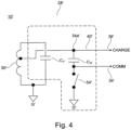
- a branch-off line is connected, wherein the branch-off line is connected to a connection point, the connection point being in connection to a charging line and a communication line, wherein in the communication line a capacitor and a connection to a switch to ground is arranged.
- the capacitor may be arranged between the connection point and the connection to the switch to ground.
- the antenna may be connected to a circuit with a capacitor and connection to ground, wherein the capacitor and the connection to ground are arranged in series.
- the capacitor and the connection to ground are arranged in series.
- this embodiment still only one antenna on the receiving side is needed, like a deep whole antenna. The individual elements will not act as a similar antenna on the same frequency.
- the receiver may be connected to a separate implantable medical device (IMD).
- IMD implantable medical device
- the implantable medical device may be an implantable pulse generator (IPG).
- IPG implantable pulse generator
- the communication and charging and/or powering system may be well defined and consist of only very few passive components. Also, no complete revision of an already implanted and existing implantable medical device is needed. So, the charging and communication system may be added to existing implanted medical devices. By separating the IMD with the system, it is also possible to design a platform independent communication and charging system, which is not directly and necessarily linked to the implantable medical device. The range of use is thereby increased.
- the implantable medical device may be rechargeable or powered (online) via the receiver by means of the charging module and that via the receiver communication signals may be exchanged between the implantable medical device (IMD) and the communication module.
- IMD implantable medical device
- the present invention is set out in the appended claims.
- Fig. 1 shows a communication and powering system 10 in a first example embodiment according to the present description.
- the communication and powering system 10 comprises an external body part 12 and an implanted in-body part 14.
- the external body part 12 is near-/on-body and for example embodied as wearable.
- the external body part 12 comprises at least one communication module 16, comprising a communication electronics 18 and an antenna coil 20.
- the communication module 16 is a communication module 16 with a communication transmitter, here the antenna coil 20, which is configured in a range to transmit and send communication signals.
- the communication module 16 is not only acting as a transmitter, but also as a receiver and thus forms a transceiver.
- the external part 12 also comprises a charging and/or powering module 22 comprising a charger 24 and an energy charging and/or powering transmitter 26.
- the energy charging and/or powering transmitter 26 is also embodied as an antenna coil 26.
- the skin barrier of the patient is also shown in Fig. 1 and denoted with reference sign S.
- the communication and powering system 10 is a medical communication and powering system 10 for transcutaneously transmitting communication signals and also energy / power for charging the energy source of an implantable medical device (IMD).
- IMD implantable medical device
- the in-body part 14 comprises a receiver 28.
- the receiver 28 is a receiver 28 for communication signals and (charging) power.
- the receiver 28 comprises an antenna / coil 30, a C/C-diplexer 32 (i.e. communication and charging diplexer 32), a communication line COMM 34 and a charging line CHARGE 36.
- the communication line COMM 34 and the charging line CHARGE 36 are connected to an implantable medical device (IMD) 38, here an implantable pulse generator (IPG) 38.
- IMD implantable medical device
- IPG implantable pulse generator
- Fig. 2 shows further details of the C/C-diplexer 32.
- the C/C-diplexer 32 has an C/C-diplexer circuit comprising the antenna coil 30, which acts as an inductor L.
- the capacitor C2 is arranged in a branch-off line 42, which is connected to line 40 at the connection point 44.
- the branch-off line 40' is connected to a connection point 34a', wherein the connection point 34a' is in connection to the charging line 36' and a communication line 34', wherein in the communication line 34' a capacitor C3' and a connection to a switch to ground G' with a switch (S) 54' is arranged.
- the order of processing is not necessarily required to achieve the features and advantages of the example embodiments described herein, but is provided for ease of illustration and description.
- One or more of the illustrated actions, operations and/or functions may be repeatedly performed depending on the particular strategy being used.
- the described actions, operations and/or functions may graphically represent code to be programmed into non-transitory memory of the computer readable storage medium in the control unit, where the described actions are carried out by executing the instructions in a system including the various hardware components in combination with the electronic control unit.
Landscapes
- Health & Medical Sciences (AREA)
- Engineering & Computer Science (AREA)
- Physics & Mathematics (AREA)
- Public Health (AREA)
- Biomedical Technology (AREA)
- Life Sciences & Earth Sciences (AREA)
- Animal Behavior & Ethology (AREA)
- General Health & Medical Sciences (AREA)
- Nuclear Medicine, Radiotherapy & Molecular Imaging (AREA)
- Veterinary Medicine (AREA)
- Radiology & Medical Imaging (AREA)
- Electromagnetism (AREA)
- Acoustics & Sound (AREA)
- Computer Networks & Wireless Communication (AREA)
- Electrotherapy Devices (AREA)
- Charge And Discharge Circuits For Batteries Or The Like (AREA)
- Near-Field Transmission Systems (AREA)
Claims (14)
- Système de communication et d'alimentation (10 ; 10'), notamment un système de communication et d'alimentation médical comprenant- au moins un module de communication (16) doté d'un émetteur de communication, qui est configuré et agencé pour transmettre et envoyer des signaux de communication,- au moins un module de charge et/ou d'alimentation (22) doté d'un émetteur de charge et/ou d'alimentation en énergie, qui est configuré et agencé pour fournir et/ou transmettre de l'énergie de charge et/ou d'alimentation,- au moins un récepteur (28 ; 28') étant un récepteur (28 ; 28') pour des signaux de communication et de l'énergie, dans lequel le récepteur (28 ; 28') est configuré pour être commuté dans un premier état de réception de signaux de communication fournis par le module de communication (16) et dans un second état de réception de l'énergie fournie par le module de charge et/ou d'alimentation (22),dans lequel le premier état et le second état sont alternés,dans lequel le récepteur (28 ; 28') comprend une antenne (30 ; 30'), notamment une bobine d'antenne, et un diplexeur de communication et de charge (32 ; 32'),dans lequel le diplexeur (32 ; 32') comprend un commutateur (54, 54') à la masse (G) et au moins un condensateur (C2 ; C3') connecté à l'antenne (30 ; 30'), l'antenne (30 ; 30') étant un inducteur (L) et le condensateur (C2, C3') étant positionné entre l'antenne (30 ; 30') et le commutateur (54, 54') à la masse (G), etdans lequel l'antenne (30 ; 30') et le condensateur (C2, C3') forment un réservoir résonant.
- Système (10 ; 10') selon la revendication 1, dans lequel l'émetteur de communication (20) est configuré et agencé pour transmettre et envoyer des signaux de communication dans une première plage de fréquences (f1) et l'émetteur de charge et/ou d'alimentation en énergie (30) est configuré et agencé pour transmettre et envoyer de l'énergie de charge dans une seconde plage de fréquences (f2), la première et la seconde plage de fréquences (f1, f2) étant différentes l'une de l'autre.
- Système (10, 10') selon la revendication 1 ou la revendication 2, dans lequel le récepteur (28 ; 28') peut être implanté ou est implanté dans un sujet et le module de communication (16) et/ou le module de charge et/ou d'alimentation (22) ne sont pas implantés dans un sujet.
- Système (10 ; 10') selon l'une des revendications précédentes, dans lequel au moins l'un parmi l'émetteur de communication (20) et l'émetteur de charge et/ou d'alimentation en énergie (26) est/sont incorporé(s) en tant qu'antenne ou bobine d'antenne.
- Système (10) selon la revendication 1, dans lequel le diplexeur (32) comprend un premier condensateur (C1) et un deuxième condensateur (C2) agencés en série et connectés à l'antenne (30 ; 30'), dans lequel l'antenne (30 ; 30') et le deuxième condensateur (C2) forment le réservoir résonant.
- Système (10) selon la revendication 5, dans lequel entre la connexion du premier condensateur (C1) et le deuxième condensateur (C2), une ligne de dérivation (48) est connectée, dans lequel la ligne de dérivation (48) est connectée à un point de connexion (46), le point de connexion (46) étant une connexion à une ligne de charge (36) et à une ligne de communication (34), dans lequel dans la ligne de communication (34) un troisième condensateur (C3) et une ligne de connexion (52) au commutateur (54) à la masse (G) sont agencés.
- Système (10) selon la revendication 6, dans lequel le troisième condensateur (C3) est agencé entre le point de connexion (46) et la ligne de connexion (52) au commutateur (54) à la masse (G).
- Système (10) selon l'une des revendications 5 à 7, dans lequel dans une ligne de connexion (42) connectant le deuxième condensateur (C2) et l'antenne (30), une connexion à la masse (G) est fournie.
- Système (10') selon la revendication 1, dans lequel une ligne de dérivation (40') est connectée à l'antenne (30'), dans lequel la ligne de dérivation (40') est connectée au point de connexion (34a'), le point de connexion (34a') étant une connexion à une ligne de charge (36') et à une ligne de communication (34'), dans lequel dans la ligne de communication (34') le condensateur (C3') et une connexion au commutateur (54') à la masse (G') sont agencés.
- Système (10') selon la revendication 9, dans lequel le condensateur (C3') est agencé entre le point de connexion (34a') et la connexion au commutateur (54') à la masse (G').
- Système (10') selon la revendication 9 ou la revendication 10, dans lequel l'antenne (30') est connectée à un circuit avec un deuxième condensateur (C1') et une connexion à la masse (G'), dans lequel le deuxième condensateur (C1') et la connexion à la masse (G') sont agencés en série.
- Système (10) selon l'une des revendications précédentes, dans lequel le récepteur (28 ; 28') est connecté à un dispositif médical pouvant être implanté (IMD) séparé.
- Système (10 ; 10') selon la revendication 12, dans lequel le dispositif médical pouvant être implanté est un générateur d'impulsions pouvant être implanté (IPG) 38.
- Système (10) selon la revendication 12 ou la revendication 13, dans lequel le dispositif médical pouvant être implanté (IMD) est rechargeable et/ou peut être alimenté en énergie par l'intermédiaire du récepteur au moyen du module de charge et/ou d'alimentation et dans lequel, par l'intermédiaire du récepteur, des signaux de communication peuvent être échangés entre le dispositif médical pouvant être implanté (IMD) et le module de communication.
Priority Applications (5)
| Application Number | Priority Date | Filing Date | Title |
|---|---|---|---|
| DE17201800.4T DE17201800T1 (de) | 2017-11-15 | 2017-11-15 | Medizinisches kommunikations- und stromladesystem |
| EP17201800.4A EP3485940B1 (fr) | 2017-11-15 | 2017-11-15 | Système de communication médicale et de charge d'énergie |
| US16/190,833 US10974052B2 (en) | 2017-11-15 | 2018-11-14 | Medical communication and power charging system |
| JP2018214267A JP7327925B2 (ja) | 2017-11-15 | 2018-11-15 | 医療用通信及び充電システム |
| CN201811360650.1A CN109787366B (zh) | 2017-11-15 | 2018-11-15 | 医疗通信和充电系统 |
Applications Claiming Priority (1)
| Application Number | Priority Date | Filing Date | Title |
|---|---|---|---|
| EP17201800.4A EP3485940B1 (fr) | 2017-11-15 | 2017-11-15 | Système de communication médicale et de charge d'énergie |
Publications (2)
| Publication Number | Publication Date |
|---|---|
| EP3485940A1 EP3485940A1 (fr) | 2019-05-22 |
| EP3485940B1 true EP3485940B1 (fr) | 2025-07-09 |
Family
ID=60327198
Family Applications (1)
| Application Number | Title | Priority Date | Filing Date |
|---|---|---|---|
| EP17201800.4A Active EP3485940B1 (fr) | 2017-11-15 | 2017-11-15 | Système de communication médicale et de charge d'énergie |
Country Status (5)
| Country | Link |
|---|---|
| US (1) | US10974052B2 (fr) |
| EP (1) | EP3485940B1 (fr) |
| JP (1) | JP7327925B2 (fr) |
| CN (1) | CN109787366B (fr) |
| DE (1) | DE17201800T1 (fr) |
Families Citing this family (4)
| Publication number | Priority date | Publication date | Assignee | Title |
|---|---|---|---|---|
| CN111817450B (zh) * | 2020-08-27 | 2021-02-05 | 鹏城实验室 | 基于磁通信的水下通信供电系统 |
| KR102896241B1 (ko) * | 2021-03-31 | 2025-12-08 | 삼성전자주식회사 | 무선 전력 수신, 무선 통신, 및 전기 자극을 수행하는 장치 및 방법 |
| DE102021124968A1 (de) | 2021-09-27 | 2023-03-30 | INNIRION GmbH | Messeinheit und Messsystem |
| WO2024054151A1 (fr) | 2022-09-08 | 2024-03-14 | Sivantos Pte. Ltd. | Topologie de bobine partagée pour communication et charge |
Citations (2)
| Publication number | Priority date | Publication date | Assignee | Title |
|---|---|---|---|---|
| EP2052758A1 (fr) * | 2007-05-31 | 2009-04-29 | Cochlear Limited | Dispositif médical implantable avec un système d'antenne intégré |
| US20160197488A1 (en) * | 2013-09-18 | 2016-07-07 | Canon Kabushiki Kaisha | Wireless power feeding system, method of controlling the same, program, and storage medium |
Family Cites Families (35)
| Publication number | Priority date | Publication date | Assignee | Title |
|---|---|---|---|---|
| US4303904A (en) * | 1979-10-12 | 1981-12-01 | Chasek Norman E | Universally applicable, in-motion and automatic toll paying system using microwaves |
| ATE149069T1 (de) * | 1989-09-29 | 1997-03-15 | Siemens Ag | Schaltungsanordnung zum ermitteln der einer atm- vermittlungsanlage im zuge von virtuellen verbindungen jeweils zugeführten nachrichtensignalmenge und zur überprüfung der einhaltung festgelegter bitraten |
| US5948004A (en) * | 1997-08-21 | 1999-09-07 | Medtroni, Inc. | Implantable stimulator having an efficient output generator |
| JP2002315209A (ja) | 2001-04-09 | 2002-10-25 | Terumo Corp | 植え込み型充電式医療装置用充電器及びシステム |
| AUPS101502A0 (en) * | 2002-03-11 | 2002-04-11 | Neopraxis Pty Ltd | Wireless fes system |
| US7437193B2 (en) * | 2002-06-28 | 2008-10-14 | Boston Scientific Neuromodulation Corporation | Microstimulator employing improved recharging reporting and telemetry techniques |
| CN1327733C (zh) * | 2002-08-08 | 2007-07-18 | 松下电器产业株式会社 | 高频器件 |
| TR200202651A2 (tr) | 2002-12-12 | 2004-07-21 | Met�N�Tulgar | VücutÁdışındanÁdirekÁtedaviÁsinyaliÁtransferliÁÁbeyinÁpili |
| US8265770B2 (en) * | 2003-10-02 | 2012-09-11 | Medtronic, Inc. | Driver circuitry switchable between energy transfer and telemetry for an implantable medical device |
| US8140168B2 (en) | 2003-10-02 | 2012-03-20 | Medtronic, Inc. | External power source for an implantable medical device having an adjustable carrier frequency and system and method related therefore |
| US9240824B2 (en) * | 2009-02-13 | 2016-01-19 | Qualcomm Incorporated | Wireless power and wireless communication for electronic devices |
| US8463392B2 (en) * | 2009-11-11 | 2013-06-11 | Boston Scientific Neuromodulation Corporation | External controller/charger system for an implantable medical device capable of automatically providing data telemetry through a charging coil during a charging session |
| CN102104366B (zh) * | 2009-12-18 | 2015-08-05 | 上海贝尔股份有限公司 | 用于tdd通信系统的功率放大装置 |
| EP2400663A1 (fr) * | 2010-06-17 | 2011-12-28 | Vetco Gray Controls Limited | Circuit d'alimentation électrique en CA |
| KR101672768B1 (ko) * | 2010-12-23 | 2016-11-04 | 삼성전자주식회사 | 무선 전력 및 데이터 송수신 시스템 |
| US20120161721A1 (en) * | 2010-12-24 | 2012-06-28 | Antony Kalugumalai Neethimanickam | Power harvesting systems |
| US9136728B2 (en) * | 2011-04-28 | 2015-09-15 | Medtronic, Inc. | Implantable medical devices and systems having inductive telemetry and recharge on a single coil |
| US8666504B2 (en) | 2011-10-24 | 2014-03-04 | Boston Scientific Neuromodulation Corporation | Communication and charging circuitry for a single-coil implantable medical device |
| WO2014126854A1 (fr) * | 2013-02-12 | 2014-08-21 | The Regents Of The University Of California | Architecture de circuit pour neurostimulateur haute tension à nombre de canaux élevé |
| WO2014125392A1 (fr) * | 2013-02-13 | 2014-08-21 | Koninklijke Philips N.V. | Circuit d'adaptation dynamique résonant pour récepteurs à transfert de puissance sans fil |
| JP6195351B2 (ja) * | 2013-05-14 | 2017-09-13 | キヤノン株式会社 | 送電装置、送電方法及びプログラム |
| US9539422B2 (en) | 2013-07-02 | 2017-01-10 | Greatbatch Ltd. | Neurostimulator interconnection apparatus, system, and method |
| KR102044952B1 (ko) * | 2013-07-17 | 2019-11-14 | 현대모비스 주식회사 | 무선 충전 기능 내장 스마트키 운영 시스템 및 및 그 방법 |
| CN203522728U (zh) * | 2013-11-05 | 2014-04-02 | 芯发威达电子(上海)有限公司 | 电子系统 |
| US9240818B2 (en) * | 2014-01-02 | 2016-01-19 | Verizon Patent And Licensing Inc. | Self protect for shared access systems |
| KR20150085641A (ko) * | 2014-01-16 | 2015-07-24 | 서울대학교산학협력단 | 휴대용 전자기기와 이를 위한 무선 충전 장치 및 무선 충전 시스템 |
| JP6619546B2 (ja) * | 2014-04-25 | 2019-12-11 | ローム株式会社 | 電力供給装置、acアダプタ、acチャージャ、電子機器および電力供給システム |
| US10411762B2 (en) | 2014-09-22 | 2019-09-10 | Canon Kabushiki Kaisha | Electronic apparatus |
| JP2016197964A (ja) | 2015-04-03 | 2016-11-24 | キヤノン株式会社 | 電子機器 |
| US9520887B1 (en) * | 2015-09-25 | 2016-12-13 | Qualcomm Incorporated | Glitch free bandwidth-switching scheme for an analog phase-locked loop (PLL) |
| US9882415B2 (en) * | 2015-10-01 | 2018-01-30 | Motorola Mobility Llc | Wireless charging architecture for mobile communication device with single piece metal housing |
| KR102386389B1 (ko) * | 2015-10-05 | 2022-04-15 | 삼성전자주식회사 | 전자 장치 및 그 제어 방법 |
| WO2017086628A1 (fr) * | 2015-11-16 | 2017-05-26 | 주식회사 맵스 | Appareil de commande de communication en champ proche et de charge sans fil à antenne unique et terminal utilisateur associé |
| US10122387B2 (en) * | 2016-05-23 | 2018-11-06 | Steven Lloyd Myers | Portable antenna with built-in amplifier for two-way or one-way communications |
| US10534203B2 (en) * | 2017-07-31 | 2020-01-14 | Snap Inc. | Near-field antenna for eyewear |
-
2017
- 2017-11-15 EP EP17201800.4A patent/EP3485940B1/fr active Active
- 2017-11-15 DE DE17201800.4T patent/DE17201800T1/de active Pending
-
2018
- 2018-11-14 US US16/190,833 patent/US10974052B2/en active Active
- 2018-11-15 JP JP2018214267A patent/JP7327925B2/ja active Active
- 2018-11-15 CN CN201811360650.1A patent/CN109787366B/zh active Active
Patent Citations (2)
| Publication number | Priority date | Publication date | Assignee | Title |
|---|---|---|---|---|
| EP2052758A1 (fr) * | 2007-05-31 | 2009-04-29 | Cochlear Limited | Dispositif médical implantable avec un système d'antenne intégré |
| US20160197488A1 (en) * | 2013-09-18 | 2016-07-07 | Canon Kabushiki Kaisha | Wireless power feeding system, method of controlling the same, program, and storage medium |
Also Published As
| Publication number | Publication date |
|---|---|
| JP7327925B2 (ja) | 2023-08-16 |
| CN109787366B (zh) | 2024-06-25 |
| US20190143128A1 (en) | 2019-05-16 |
| CN109787366A (zh) | 2019-05-21 |
| DE17201800T1 (de) | 2019-09-26 |
| US10974052B2 (en) | 2021-04-13 |
| JP2019088788A (ja) | 2019-06-13 |
| EP3485940A1 (fr) | 2019-05-22 |
Similar Documents
| Publication | Publication Date | Title |
|---|---|---|
| US10974052B2 (en) | Medical communication and power charging system | |
| US8081925B2 (en) | Transceiver for an implantable medical device having switchable series-to-parallel tank circuit | |
| AU2010318593B2 (en) | Structure for an implantable medical device having telemetry and charging coils within a case | |
| EP2633631B1 (fr) | Système de communication à induction magnétique pour dispositif médical implantable | |
| CA2687456C (fr) | Telemesure de donnees induites par un champ tournant et transfert de puissance dans un systeme de dispositif medical implantable | |
| US20240366950A1 (en) | Radio Frequency Antenna Capacitively Coupled to a Charging Coil in an Implantable Medical Device | |
| EP3678734B1 (fr) | Dispositif médical implantable à antenne cadre multibande | |
| KR102770797B1 (ko) | 무선 전력 수신 장치 및 오브젝트 자극 장치 | |
| WO2009012009A1 (fr) | Circuit d'attaque résonant efficace en termes de consommation d'énergie pour une télémétrie couplée magnétiquement | |
| US9067072B2 (en) | Switchable dual-coil communication circuitry for extending communication range in an implantable medical device system | |
| JP2012195938A (ja) | データ転送システムおよびその管理方法 | |
| WO2010049849A1 (fr) | Réutilisation d’un filet de vis | |
| US20250339696A1 (en) | Implantable medical device system with multi-band antenna arrangement | |
| Ghovanloo et al. | Inductive coupling | |
| Adeeb et al. | Research Article An Inductive Link-Based Wireless Power Transfer System for Biomedical Applications |
Legal Events
| Date | Code | Title | Description |
|---|---|---|---|
| PUAI | Public reference made under article 153(3) epc to a published international application that has entered the european phase |
Free format text: ORIGINAL CODE: 0009012 |
|
| STAA | Information on the status of an ep patent application or granted ep patent |
Free format text: STATUS: THE APPLICATION HAS BEEN PUBLISHED |
|
| AK | Designated contracting states |
Kind code of ref document: A1 Designated state(s): AL AT BE BG CH CY CZ DE DK EE ES FI FR GB GR HR HU IE IS IT LI LT LU LV MC MK MT NL NO PL PT RO RS SE SI SK SM TR |
|
| AX | Request for extension of the european patent |
Extension state: BA ME |
|
| REG | Reference to a national code |
Ref country code: DE Ref legal event code: R210 |
|
| STAA | Information on the status of an ep patent application or granted ep patent |
Free format text: STATUS: REQUEST FOR EXAMINATION WAS MADE |
|
| 17P | Request for examination filed |
Effective date: 20191119 |
|
| RBV | Designated contracting states (corrected) |
Designated state(s): AL AT BE BG CH CY CZ DE DK EE ES FI FR GB GR HR HU IE IS IT LI LT LU LV MC MK MT NL NO PL PT RO RS SE SI SK SM TR |
|
| RAP1 | Party data changed (applicant data changed or rights of an application transferred) |
Owner name: ONWARD MEDICAL B.V. |
|
| RAP3 | Party data changed (applicant data changed or rights of an application transferred) |
Owner name: ONWARD MEDICAL N.V. |
|
| STAA | Information on the status of an ep patent application or granted ep patent |
Free format text: STATUS: EXAMINATION IS IN PROGRESS |
|
| 17Q | First examination report despatched |
Effective date: 20220609 |
|
| RAP3 | Party data changed (applicant data changed or rights of an application transferred) |
Owner name: ONWARD MEDICAL N.V. |
|
| 111Z | Information provided on other rights and legal means of execution |
Free format text: AL AT BE BG CH CY CZ DE DK EE ES FI FR GB GR HR HU IE IS IT LT LU LV MC MK MT NL NO PL PT RO RS SE SI SK SM TR Effective date: 20240724 |
|
| GRAP | Despatch of communication of intention to grant a patent |
Free format text: ORIGINAL CODE: EPIDOSNIGR1 |
|
| STAA | Information on the status of an ep patent application or granted ep patent |
Free format text: STATUS: GRANT OF PATENT IS INTENDED |
|
| RIC1 | Information provided on ipc code assigned before grant |
Ipc: A61N 1/372 20060101ALI20250201BHEP Ipc: A61N 1/378 20060101AFI20250201BHEP |
|
| INTG | Intention to grant announced |
Effective date: 20250213 |
|
| P01 | Opt-out of the competence of the unified patent court (upc) registered |
Free format text: CASE NUMBER: APP_8745/2025 Effective date: 20250220 |
|
| GRAS | Grant fee paid |
Free format text: ORIGINAL CODE: EPIDOSNIGR3 |
|
| GRAA | (expected) grant |
Free format text: ORIGINAL CODE: 0009210 |
|
| STAA | Information on the status of an ep patent application or granted ep patent |
Free format text: STATUS: THE PATENT HAS BEEN GRANTED |
|
| REG | Reference to a national code |
Ref country code: DE Ref legal event code: R082 Ref document number: 602017090424 Country of ref document: DE Ref country code: DE Ref legal event code: R081 Ref document number: 602017090424 Country of ref document: DE Owner name: ONWARD MEDICAL N.V., NL Free format text: FORMER OWNER: GTX MEDICAL B.V., EINDHOVEN, NL |
|
| AK | Designated contracting states |
Kind code of ref document: B1 Designated state(s): AL AT BE BG CH CY CZ DE DK EE ES FI FR GB GR HR HU IE IS IT LI LT LU LV MC MK MT NL NO PL PT RO RS SE SI SK SM TR |
|
| REG | Reference to a national code |
Ref country code: GB Ref legal event code: FG4D |
|
| REG | Reference to a national code |
Ref country code: CH Ref legal event code: EP |
|
| REG | Reference to a national code |
Ref country code: IE Ref legal event code: FG4D |
|
| REG | Reference to a national code |
Ref country code: DE Ref legal event code: R096 Ref document number: 602017090424 Country of ref document: DE |
|
| REG | Reference to a national code |
Ref country code: NL Ref legal event code: MP Effective date: 20250709 |
|
| PG25 | Lapsed in a contracting state [announced via postgrant information from national office to epo] |
Ref country code: PT Free format text: LAPSE BECAUSE OF FAILURE TO SUBMIT A TRANSLATION OF THE DESCRIPTION OR TO PAY THE FEE WITHIN THE PRESCRIBED TIME-LIMIT Effective date: 20251110 |
|
| PG25 | Lapsed in a contracting state [announced via postgrant information from national office to epo] |
Ref country code: NL Free format text: LAPSE BECAUSE OF FAILURE TO SUBMIT A TRANSLATION OF THE DESCRIPTION OR TO PAY THE FEE WITHIN THE PRESCRIBED TIME-LIMIT Effective date: 20250709 |
|
| REG | Reference to a national code |
Ref country code: AT Ref legal event code: MK05 Ref document number: 1811314 Country of ref document: AT Kind code of ref document: T Effective date: 20250709 |
|
| PG25 | Lapsed in a contracting state [announced via postgrant information from national office to epo] |
Ref country code: IS Free format text: LAPSE BECAUSE OF FAILURE TO SUBMIT A TRANSLATION OF THE DESCRIPTION OR TO PAY THE FEE WITHIN THE PRESCRIBED TIME-LIMIT Effective date: 20251109 |
|
| PG25 | Lapsed in a contracting state [announced via postgrant information from national office to epo] |
Ref country code: NO Free format text: LAPSE BECAUSE OF FAILURE TO SUBMIT A TRANSLATION OF THE DESCRIPTION OR TO PAY THE FEE WITHIN THE PRESCRIBED TIME-LIMIT Effective date: 20251009 |
|
| REG | Reference to a national code |
Ref country code: LT Ref legal event code: MG9D |
|
| PG25 | Lapsed in a contracting state [announced via postgrant information from national office to epo] |
Ref country code: AT Free format text: LAPSE BECAUSE OF FAILURE TO SUBMIT A TRANSLATION OF THE DESCRIPTION OR TO PAY THE FEE WITHIN THE PRESCRIBED TIME-LIMIT Effective date: 20250709 |
|
| PG25 | Lapsed in a contracting state [announced via postgrant information from national office to epo] |
Ref country code: FI Free format text: LAPSE BECAUSE OF FAILURE TO SUBMIT A TRANSLATION OF THE DESCRIPTION OR TO PAY THE FEE WITHIN THE PRESCRIBED TIME-LIMIT Effective date: 20250709 |
|
| PG25 | Lapsed in a contracting state [announced via postgrant information from national office to epo] |
Ref country code: HR Free format text: LAPSE BECAUSE OF FAILURE TO SUBMIT A TRANSLATION OF THE DESCRIPTION OR TO PAY THE FEE WITHIN THE PRESCRIBED TIME-LIMIT Effective date: 20250709 |
|
| PG25 | Lapsed in a contracting state [announced via postgrant information from national office to epo] |
Ref country code: GR Free format text: LAPSE BECAUSE OF FAILURE TO SUBMIT A TRANSLATION OF THE DESCRIPTION OR TO PAY THE FEE WITHIN THE PRESCRIBED TIME-LIMIT Effective date: 20251010 |
|
| PG25 | Lapsed in a contracting state [announced via postgrant information from national office to epo] |
Ref country code: SE Free format text: LAPSE BECAUSE OF FAILURE TO SUBMIT A TRANSLATION OF THE DESCRIPTION OR TO PAY THE FEE WITHIN THE PRESCRIBED TIME-LIMIT Effective date: 20250709 |
|
| PG25 | Lapsed in a contracting state [announced via postgrant information from national office to epo] |
Ref country code: LV Free format text: LAPSE BECAUSE OF FAILURE TO SUBMIT A TRANSLATION OF THE DESCRIPTION OR TO PAY THE FEE WITHIN THE PRESCRIBED TIME-LIMIT Effective date: 20250709 |
|
| PG25 | Lapsed in a contracting state [announced via postgrant information from national office to epo] |
Ref country code: PL Free format text: LAPSE BECAUSE OF FAILURE TO SUBMIT A TRANSLATION OF THE DESCRIPTION OR TO PAY THE FEE WITHIN THE PRESCRIBED TIME-LIMIT Effective date: 20250709 Ref country code: BG Free format text: LAPSE BECAUSE OF FAILURE TO SUBMIT A TRANSLATION OF THE DESCRIPTION OR TO PAY THE FEE WITHIN THE PRESCRIBED TIME-LIMIT Effective date: 20250709 |
|
| PG25 | Lapsed in a contracting state [announced via postgrant information from national office to epo] |
Ref country code: RS Free format text: LAPSE BECAUSE OF FAILURE TO SUBMIT A TRANSLATION OF THE DESCRIPTION OR TO PAY THE FEE WITHIN THE PRESCRIBED TIME-LIMIT Effective date: 20251009 |
|
| PG25 | Lapsed in a contracting state [announced via postgrant information from national office to epo] |
Ref country code: ES Free format text: LAPSE BECAUSE OF FAILURE TO SUBMIT A TRANSLATION OF THE DESCRIPTION OR TO PAY THE FEE WITHIN THE PRESCRIBED TIME-LIMIT Effective date: 20250709 |
|
| PG25 | Lapsed in a contracting state [announced via postgrant information from national office to epo] |
Ref country code: RO Free format text: LAPSE BECAUSE OF FAILURE TO SUBMIT A TRANSLATION OF THE DESCRIPTION OR TO PAY THE FEE WITHIN THE PRESCRIBED TIME-LIMIT Effective date: 20250709 |
|
| PG25 | Lapsed in a contracting state [announced via postgrant information from national office to epo] |
Ref country code: SM Free format text: LAPSE BECAUSE OF FAILURE TO SUBMIT A TRANSLATION OF THE DESCRIPTION OR TO PAY THE FEE WITHIN THE PRESCRIBED TIME-LIMIT Effective date: 20250709 |
|
| PG25 | Lapsed in a contracting state [announced via postgrant information from national office to epo] |
Ref country code: DK Free format text: LAPSE BECAUSE OF FAILURE TO SUBMIT A TRANSLATION OF THE DESCRIPTION OR TO PAY THE FEE WITHIN THE PRESCRIBED TIME-LIMIT Effective date: 20250709 |
|
| PG25 | Lapsed in a contracting state [announced via postgrant information from national office to epo] |
Ref country code: IT Free format text: LAPSE BECAUSE OF FAILURE TO SUBMIT A TRANSLATION OF THE DESCRIPTION OR TO PAY THE FEE WITHIN THE PRESCRIBED TIME-LIMIT Effective date: 20250709 |
|
| PG25 | Lapsed in a contracting state [announced via postgrant information from national office to epo] |
Ref country code: CZ Free format text: LAPSE BECAUSE OF FAILURE TO SUBMIT A TRANSLATION OF THE DESCRIPTION OR TO PAY THE FEE WITHIN THE PRESCRIBED TIME-LIMIT Effective date: 20250709 |
|
| PG25 | Lapsed in a contracting state [announced via postgrant information from national office to epo] |
Ref country code: EE Free format text: LAPSE BECAUSE OF FAILURE TO SUBMIT A TRANSLATION OF THE DESCRIPTION OR TO PAY THE FEE WITHIN THE PRESCRIBED TIME-LIMIT Effective date: 20250709 Ref country code: SK Free format text: LAPSE BECAUSE OF FAILURE TO SUBMIT A TRANSLATION OF THE DESCRIPTION OR TO PAY THE FEE WITHIN THE PRESCRIBED TIME-LIMIT Effective date: 20250709 |