EP3486101A1 - Boîtier de batterie pour véhicule et procédé de fabrication de boîtier de batterie - Google Patents
Boîtier de batterie pour véhicule et procédé de fabrication de boîtier de batterie Download PDFInfo
- Publication number
- EP3486101A1 EP3486101A1 EP18198000.4A EP18198000A EP3486101A1 EP 3486101 A1 EP3486101 A1 EP 3486101A1 EP 18198000 A EP18198000 A EP 18198000A EP 3486101 A1 EP3486101 A1 EP 3486101A1
- Authority
- EP
- European Patent Office
- Prior art keywords
- inner panel
- vehicle
- joined
- outer panel
- panel
- Prior art date
- Legal status (The legal status is an assumption and is not a legal conclusion. Google has not performed a legal analysis and makes no representation as to the accuracy of the status listed.)
- Granted
Links
Images


Classifications
-
- B—PERFORMING OPERATIONS; TRANSPORTING
- B60—VEHICLES IN GENERAL
- B60K—ARRANGEMENT OR MOUNTING OF PROPULSION UNITS OR OF TRANSMISSIONS IN VEHICLES; ARRANGEMENT OR MOUNTING OF PLURAL DIVERSE PRIME-MOVERS IN VEHICLES; AUXILIARY DRIVES FOR VEHICLES; INSTRUMENTATION OR DASHBOARDS FOR VEHICLES; ARRANGEMENTS IN CONNECTION WITH COOLING, AIR INTAKE, GAS EXHAUST OR FUEL SUPPLY OF PROPULSION UNITS IN VEHICLES
- B60K1/00—Arrangement or mounting of electrical propulsion units
- B60K1/04—Arrangement or mounting of electrical propulsion units of the electric storage means for propulsion
-
- B—PERFORMING OPERATIONS; TRANSPORTING
- B60—VEHICLES IN GENERAL
- B60L—PROPULSION OF ELECTRICALLY-PROPELLED VEHICLES; SUPPLYING ELECTRIC POWER FOR AUXILIARY EQUIPMENT OF ELECTRICALLY-PROPELLED VEHICLES; ELECTRODYNAMIC BRAKE SYSTEMS FOR VEHICLES IN GENERAL; MAGNETIC SUSPENSION OR LEVITATION FOR VEHICLES; MONITORING OPERATING VARIABLES OF ELECTRICALLY-PROPELLED VEHICLES; ELECTRIC SAFETY DEVICES FOR ELECTRICALLY-PROPELLED VEHICLES
- B60L50/00—Electric propulsion with power supplied within the vehicle
- B60L50/50—Electric propulsion with power supplied within the vehicle using propulsion power supplied by batteries or fuel cells
- B60L50/60—Electric propulsion with power supplied within the vehicle using propulsion power supplied by batteries or fuel cells using power supplied by batteries
- B60L50/64—Constructional details of batteries specially adapted for electric vehicles
-
- B—PERFORMING OPERATIONS; TRANSPORTING
- B60—VEHICLES IN GENERAL
- B60L—PROPULSION OF ELECTRICALLY-PROPELLED VEHICLES; SUPPLYING ELECTRIC POWER FOR AUXILIARY EQUIPMENT OF ELECTRICALLY-PROPELLED VEHICLES; ELECTRODYNAMIC BRAKE SYSTEMS FOR VEHICLES IN GENERAL; MAGNETIC SUSPENSION OR LEVITATION FOR VEHICLES; MONITORING OPERATING VARIABLES OF ELECTRICALLY-PROPELLED VEHICLES; ELECTRIC SAFETY DEVICES FOR ELECTRICALLY-PROPELLED VEHICLES
- B60L50/00—Electric propulsion with power supplied within the vehicle
- B60L50/50—Electric propulsion with power supplied within the vehicle using propulsion power supplied by batteries or fuel cells
- B60L50/60—Electric propulsion with power supplied within the vehicle using propulsion power supplied by batteries or fuel cells using power supplied by batteries
- B60L50/66—Arrangements of batteries
-
- H—ELECTRICITY
- H01—ELECTRIC ELEMENTS
- H01M—PROCESSES OR MEANS, e.g. BATTERIES, FOR THE DIRECT CONVERSION OF CHEMICAL ENERGY INTO ELECTRICAL ENERGY
- H01M50/00—Constructional details or processes of manufacture of the non-active parts of electrochemical cells other than fuel cells, e.g. hybrid cells
- H01M50/20—Mountings; Secondary casings or frames; Racks, modules or packs; Suspension devices; Shock absorbers; Transport or carrying devices; Holders
- H01M50/218—Mountings; Secondary casings or frames; Racks, modules or packs; Suspension devices; Shock absorbers; Transport or carrying devices; Holders characterised by the material
- H01M50/22—Mountings; Secondary casings or frames; Racks, modules or packs; Suspension devices; Shock absorbers; Transport or carrying devices; Holders characterised by the material of the casings or racks
- H01M50/222—Inorganic material
- H01M50/224—Metals
-
- H—ELECTRICITY
- H01—ELECTRIC ELEMENTS
- H01M—PROCESSES OR MEANS, e.g. BATTERIES, FOR THE DIRECT CONVERSION OF CHEMICAL ENERGY INTO ELECTRICAL ENERGY
- H01M50/00—Constructional details or processes of manufacture of the non-active parts of electrochemical cells other than fuel cells, e.g. hybrid cells
- H01M50/20—Mountings; Secondary casings or frames; Racks, modules or packs; Suspension devices; Shock absorbers; Transport or carrying devices; Holders
- H01M50/249—Mountings; Secondary casings or frames; Racks, modules or packs; Suspension devices; Shock absorbers; Transport or carrying devices; Holders specially adapted for aircraft or vehicles, e.g. cars or trains
-
- B—PERFORMING OPERATIONS; TRANSPORTING
- B60—VEHICLES IN GENERAL
- B60K—ARRANGEMENT OR MOUNTING OF PROPULSION UNITS OR OF TRANSMISSIONS IN VEHICLES; ARRANGEMENT OR MOUNTING OF PLURAL DIVERSE PRIME-MOVERS IN VEHICLES; AUXILIARY DRIVES FOR VEHICLES; INSTRUMENTATION OR DASHBOARDS FOR VEHICLES; ARRANGEMENTS IN CONNECTION WITH COOLING, AIR INTAKE, GAS EXHAUST OR FUEL SUPPLY OF PROPULSION UNITS IN VEHICLES
- B60K1/00—Arrangement or mounting of electrical propulsion units
- B60K1/04—Arrangement or mounting of electrical propulsion units of the electric storage means for propulsion
- B60K2001/0405—Arrangement or mounting of electrical propulsion units of the electric storage means for propulsion characterised by their position
- B60K2001/0438—Arrangement under the floor
-
- B—PERFORMING OPERATIONS; TRANSPORTING
- B60—VEHICLES IN GENERAL
- B60Y—INDEXING SCHEME RELATING TO ASPECTS CROSS-CUTTING VEHICLE TECHNOLOGY
- B60Y2306/00—Other features of vehicle sub-units
- B60Y2306/01—Reducing damages in case of crash, e.g. by improving battery protection
-
- H—ELECTRICITY
- H01—ELECTRIC ELEMENTS
- H01M—PROCESSES OR MEANS, e.g. BATTERIES, FOR THE DIRECT CONVERSION OF CHEMICAL ENERGY INTO ELECTRICAL ENERGY
- H01M2220/00—Batteries for particular applications
- H01M2220/20—Batteries in motive systems, e.g. vehicle, ship, plane
-
- Y—GENERAL TAGGING OF NEW TECHNOLOGICAL DEVELOPMENTS; GENERAL TAGGING OF CROSS-SECTIONAL TECHNOLOGIES SPANNING OVER SEVERAL SECTIONS OF THE IPC; TECHNICAL SUBJECTS COVERED BY FORMER USPC CROSS-REFERENCE ART COLLECTIONS [XRACs] AND DIGESTS
- Y02—TECHNOLOGIES OR APPLICATIONS FOR MITIGATION OR ADAPTATION AGAINST CLIMATE CHANGE
- Y02E—REDUCTION OF GREENHOUSE GAS [GHG] EMISSIONS, RELATED TO ENERGY GENERATION, TRANSMISSION OR DISTRIBUTION
- Y02E60/00—Enabling technologies; Technologies with a potential or indirect contribution to GHG emissions mitigation
- Y02E60/10—Energy storage using batteries
-
- Y—GENERAL TAGGING OF NEW TECHNOLOGICAL DEVELOPMENTS; GENERAL TAGGING OF CROSS-SECTIONAL TECHNOLOGIES SPANNING OVER SEVERAL SECTIONS OF THE IPC; TECHNICAL SUBJECTS COVERED BY FORMER USPC CROSS-REFERENCE ART COLLECTIONS [XRACs] AND DIGESTS
- Y02—TECHNOLOGIES OR APPLICATIONS FOR MITIGATION OR ADAPTATION AGAINST CLIMATE CHANGE
- Y02T—CLIMATE CHANGE MITIGATION TECHNOLOGIES RELATED TO TRANSPORTATION
- Y02T10/00—Road transport of goods or passengers
- Y02T10/60—Other road transportation technologies with climate change mitigation effect
- Y02T10/70—Energy storage systems for electromobility, e.g. batteries
Definitions
- the present disclosure relates to a battery case for a vehicle that houses a battery and is installed beneath the floor of a vehicle, and to a method of manufacturing the battery case for a vehicle.
- the battery pack for an electric vehicle that is disclosed in Japanese Patent Application Laid-Open ( JP-A) No. 2015-170452 has a battery case that is installed beneath the floor of a vehicle.
- This battery case has a tray that is box-shaped and houses a battery, an outer frame that is disposed at the outer side of the tray, and plural inner frames and cross beams that are disposed at the inner side of the tray.
- These tray, outer frame, inner frames and cross beams are all formed of steel plates.
- the inner frames and the cross beams respectively are joined by spot welding in states of being superposed in three layers together with the tray and the outer frame.
- the outer frame, together with the tray forms a side wall that has a closed cross-sectional shape.
- the side wall is supported from the inner side of the tray by the inner frames and the cross beams (both are supporting members). Due thereto, the strength of the battery case with respect to load from the vehicle transverse direction outer side is increased. In this battery case, openings (work holes) through which a gun for spot welding is inserted are formed in the outer frame.
- the following disadvantages arise due to openings being formed in the outer frame. Namely, additional processes for forming the openings are needed, and the strength of the outer frame at the portions where the openings are formed decreases. Further, members for closing-off the openings are needed in order to prevent water and the like from penetrating into the outer frame. For the above reasons, problems such as the manufacturing cost increasing and the weight increasing and the like arise, and therefore, there is room for improvement.
- the side wall which has a closed cross-sectional shape and is formed by the outer frame and the tray, is crushed (the cross-section thereof collapses) due to load from the vehicle transverse direction outer side (the side opposite the cross beams), it is difficult for this load to be transmitted to the cross beams. As a result, the amount of deformation of the tray is large, and there is the possibility that the battery within the tray will be damaged. Further, in the above-described related art, the side wall bendingly deforming in front of and at the rear of a cross beam due to load from the vehicle transverse direction outer side is suppressed by the inner frames that are disposed within the tray. Therefore, the space for accommodating the battery is reduced by the space for the provision of the inner frames. For the above reasons, in the above-described related art, there is room for improvement also from the standpoint of efficiently suppressing the above-described deformation of the side wall.
- An object of the present disclosure is to provide a battery case for a vehicle and a method of manufacturing the battery case that, in a structure in which a side wall that forms a closed cross-section and supporting members that support the side wall from a case inner side are joined by spot welding, can efficiently suppress deformation of the side wall due to load from the side opposite the supporting members, without necessitating the formation of openings for spot welding in the side wall.
- a first aspect is a battery case for a vehicle that houses a battery.
- the battery case includes: a bottom plate, a side wall, and supporting members that are joined to the bottom plate and that support the side wall from a case inner side, wherein the battery case is installed beneath a floor of a vehicle, the side wall has an inner panel to which the supporting members are joined by spot welding, and an outer panel that faces the inner panel from a side that is opposite from the supporting members, upper portions of the inner panel and the outer panel are joined together by spot welding, and lower end portions of the inner panel and the outer panel are joined to or made integral with the bottom plate, at a vertical direction intermediate portion of one of the inner panel or the outer panel, there is formed a bulging portion which bulges out toward another of the inner panel or the outer panel and is joined to the other of the inner panel or the outer panel by spot welding, closed cross-section portions are formed at the side wall at both an upper side and a lower side of the bulging portion, respectively, and weld points of the spot welding that join the inner
- “Joined to or made integral with” in the first aspect is either of a case in which the respective lower ends of the inner panel and the outer panel are joined to the bottom plate, and a case in which the lower end of one either one of the inner panel and the outer panel is made integral with the bottom plate and the lower end of the other is joined to the bottom plate.
- the battery case for a vehicle of the first aspect houses a battery and is installed beneath the floor.
- This battery case for a vehicle has the bottom plate, the side wall, and the supporting members that are joined to the bottom plate and that support the side wall from the case inner side.
- the side wall has the inner panel to which the supporting members are joined by spot welding, and the outer panel that faces the inner panel from the side opposite the supporting members.
- the upper portions of the inner panel and the outer panel are joined together by spot welding.
- the lower end portions of the inner panel and the outer panel are joined to or are made integral with the bottom plate.
- a bulging portion which bulges-out toward the other and is joined to the other by spot welding, is formed. Closed cross-section portions are formed at the side wall at the upper and lower both sides of the bulging portion, respectively.
- the weld points of the spot welding that join the inner panel and the outer panel as described above are disposed at positions that do not overlap the supporting members as seen from the direction in which the inner panel and the outer panel face one another. Therefore, at the time of joining the side wall, which has a closed cross-section, and the supporting members, which support the side wall from the case inner side, by spot welding as described above, first, the supporting members and the inner panel are spot welded, and thereafter, it suffices to spot weld the inner panel and the outer panel at the above-described non-overlapping positions, and there is no need to form openings for the insertion of a gun for spot welding in the side wall.
- the bulging portion that is provided at one of the inner panel and the outer panel i.e., a portion of the side wall, suppresses deformation of the side wall due to load from the side opposite the supporting members (hereinafter simply called "load"), and therefore, deformation of the side wall can be suppressed efficiently.
- a second aspect is the first aspect of the battery case for a vehicle, wherein the bulging portion is formed at the vertical direction intermediate portion of the inner panel.
- the bulging portion which bulges-out toward the outer panel side and is joined to the outer panel, is formed at the vertical direction intermediate portion of the inner panel that side wall has.
- a recess is formed in the outer panel at the surface thereof that is at the side opposite the inner panel (the surface that is at the case outer side). Therefore, there is the possibility that water or foreign matter or the like will collect in this recess, but this can be avoided in the present disclosure.
- the closed cross-section portions which are formed at the upper and lower both sides of the bulging portion at the side wall respectively, are joined to the supporting members. Due thereto, the upper and lower closed cross-section portions are connected via the supporting members, and therefore, the side wall deforming due to load can be suppressed more efficiently.
- the bottom plate, the inner panel, the outer panel and the supporting members are formed by steel plates. Therefore, as compared with a case in which these members are formed of a light metal such as aluminum or the like or an alloy thereof, the manufacturing cost can be reduced. Moreover, because the bottom plate is joined by spot welding to the inner panel, the outer panel and the supporting members, the above-described respective members can be joined by only spot welding. Accordingly, manufacturing is easy.
- the inner panel, the outer panel and the supporting members are formed by steel plates
- the bottom plate is formed by a plate member that is a light metal or a light alloy
- the bottom plate is joined to the inner panel, the outer panel and the supporting members by mechanical fastening.
- the inner panel, the outer panel and the supporting members that are steel plates, and the bottom plate that is a plate member of a light metal or a light alloy, are joined by mechanical fastening. Due thereto, lightening of the weight can be devised by the bottom plate that is made of a light metal or a light alloy, while the strength of the side wall with respect to load is ensured by the inner panel, the outer panel and the supporting members that are made of steel plates.
- the sixth aspect of a method of manufacturing the battery case for a vehicle of the fourth aspect or fifth aspect includes: joining the supporting members and the inner panel by spot welding; joining the inner panel and the outer panel by spot welding; and joining the inner panel, the outer panel and the supporting members, to the bottom plate, by spot welding or mechanical fastening.
- the supporting members and the inner panel are joined by spot welding.
- the inner panel and the outer panel are joined by spot welding.
- the inner panel, the outer panel and the supporting members, and the bottom plate are joined by spot welding or mechanical fastening.
- a battery case 10 for a vehicle relating to a first embodiment of the present disclosure (hereinafter simply called “battery case 10") and a method of manufacturing thereof are described hereinafter by using Fig. 1 through Fig. 8 .
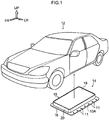
- arrow FR, arrow UP and arrow LH that are shown appropriately in the respective drawings indicate the forward direction (the advancing direction), the upward direction and the leftward direction, respectively, of an electric automobile (vehicle) 12 at which the battery case 10 for a vehicle is installed beneath the floor.
- the electric automobile 12 relating to the present embodiment has a battery pack 14 for a vehicle (hereinafter simply called "battery pack 14") that is installed beneath the floor of the vehicle cabin.
- This battery back 14 is for supplying electric power to electric equipment for causing the electric automobile 12 to travel, an air conditioner of the electric automobile 12, and the like, and has the battery case 10 and incorporated parts such as a battery or the like that are accommodated at the interior of the battery case 10.
- the battery is structured by plural battery modules. Each of the battery modules is structured by, for example, plural square-type storage batteries being made into a module.
- the overall structure of the battery case 10 will be described first, and thereafter, the structure of main portions of the present embodiment, and the method of manufacturing the battery case 10, will be described successively.
- the battery case 10 is shaped as a box whose length direction is the vehicle longitudinal direction and that is flat in the vehicle vertical direction, and is fixed to the vehicle body of the electric automobile 12 by fastening by bolts.
- the battery case 10 has a bottom plate 16 that forms the lower surface of the battery case 10, an upper lid 18 that forms the upper surface of the battery case 10, a side wall (peripheral wall) 20 that forms the outer peripheral surface of the battery case 10, a center beam 38 (see Fig. 2 ) that is disposed at the vehicle transverse direction center of the battery case 10 interior, and plural (here, 12) cross beams 40 that support the side wall 20 from the case inner side.
- the cross beams 40 correspond to the "supporting members" of the present disclosure.
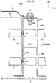
- 42 and 44 that are shown in Fig. 3 and Fig. 4 are sealers that block water at the mating portion of the final end portion of the upper lid 18 and the side wall 20, and the mating portion of the side wall 20 and the bottom plate 16.
- the bottom plate 16, the upper lid 18, the side wall 20, the center beam 38 and the cross beams 40 are all formed by steel plates.
- the bottom plate 16, the side wall 20 and the cross beams 40 are joined together by spot welding.
- the center beam 38 is joined to (united with) the bottom plate 16 by spot welding.
- the upper lid 18 is joined to (united with) the side wall 20 by fastening by bolts. Note that there may be a structure in which all of or some of the above-described respective members are formed of a light metal such as aluminum or the like or of an alloy thereof.
- the bottom plate 16 and the upper lid 18 are formed by steel plates being press-molded into the shapes of plates that are elongated and rectangular, and are disposed with the length directions thereof being the vehicle longitudinal direction and the plate thickness directions thereof being the vehicle vertical direction.
- the side wall 20 is shaped as a frame that is elongated and rectangular and whose long side runs along the vehicle longitudinal direction as seen from the vehicle vertical direction.
- the side wall 20 is structured by a pair of left and right rectilinear portions 20A, a pair of front and rear rectilinear portions 20B, and four corner portions 20C that connect these rectilinear portions 20A, 20B.
- the left and right rectilinear portions 20A extend in the vehicle longitudinal direction
- the front and rear rectilinear portions 20B extend in the vehicle transverse direction. The structure of this side wall 20 is described in detail later.
- the center beam 38 is formed in an elongated shape due to a steel plate being roll-formed or press-molded, and is disposed at the center between the left and right rectilinear portions 20A with the length direction thereof being the vehicle longitudinal direction.
- the cross-section seen from the vehicle longitudinal direction of the center beam 38 is hat-shaped, and a pair of left and right lower flange portions that are formed at the lower end portion are joined to the top surface of the bottom plate 16 by spot welding.
- the plural cross beams 40 are formed in elongated shapes due to steel plates being roll-formed or press-molded, and are disposed between the left rectilinear portion 20A and the center beam 38, and between the right rectilinear portion 20A and the center beam 38, with the length directions thereof being the vehicle transverse direction.
- plural (here, six) pairs of the cross beams 40 which are disposed so as to be lined-up in the vehicle transverse direction at the both sides of the center beam 38, are disposed at intervals in the vehicle longitudinal direction.
- the height dimension of these cross beams 40 is set to be higher than the height dimension of the center beam 38.
- each of the cross beams 40 The cross-section seen from the vehicle transverse direction of each of the cross beams 40 is hat-shaped, and a pair of front and rear lower flange portions (see Fig. 2 ) that are formed at the lower end portion of the cross beam 40 are joined by spot welding to the top surface of the bottom plate 16. Further, a pair of front and rear lateral flange portions 40A that project-out toward the vehicle longitudinal direction both sides are formed at the vehicle transverse direction end portions of each of the cross beams 40. The front and rear lateral flange portions 40A are joined by spot welding to the left and right rectilinear portions 20A.
- the left and right rectilinear portions 20A of the above-described side wall 20 are supported from the case inner side by the plural cross beams 40.
- Each of the left and right rectilinear portions 20A is structured by an inner panel 22 to which the lateral flange portions 40A of the cross beams 40 are joined by spot welding, and an outer panel 24 that is disposed at the side of the inner panel 22 which side is opposite the side at which the cross beams 40 are located (i.e., the outer panel 24 is disposed at the vehicle transverse direction outer side of the inner panel 22).
- the battery case 10 is structured so as to be symmetrical to the left and right, the structure of the left side portion of the battery case 10 is described hereinafter, and description of the structure of the right side portion is omitted. Further, in the following description, there are cases in which the rectilinear portion 20A at the left is simply called the “rectilinear portion 20A", and the plural cross beams 40 are simply called the “cross beams 40”, and the front and rear lateral flange portions 40A of the cross beam 40 are simply called the "lateral flange portions 40A".
- the inner panel 22 and the outer panel 24 are formed in elongated shapes by steel plates being roll-hemmed, and are disposed with the length directions thereof being the vehicle longitudinal direction and the thickness directions thereof being the vehicle transverse direction.
- the upper portions of the inner panel 22 and the outer panel 24 are joined together by spot welding, and the lower end portions are joined to the bottom plate 16 by spot welding.
- the weld points of the aforementioned spot welding are set at multiple places that are lined-up in the vehicle longitudinal direction. Further, the multiple weld points (refer to weld points S3, S4 in Fig. 4 ) of the spot welding that joins the inner panel 22 and the outer panel 24 are disposed at positions that do not overlap the cross beams 40 as seen from the direction in which the inner panel 22 and the outer panel 24 face one another (the vehicle transverse direction). Details thereof are described hereinafter.
- the cross-section seen from the vehicle longitudinal direction (the length direction) of the outer panel 24 is bent in the shape of a crank, and is a cross-section of the same shape in the length direction.
- the outer panel 24 is structured by a vertical wall portion 24A that extends in the vehicle vertical direction as seen in the vehicle longitudinal direction, an upper flange portion 24B that extends toward the vehicle transverse direction inner side from the upper end portion of the vertical wall portion 24A, and a lower flange portion 24C that extends toward the vehicle transverse direction outer side from the lower end portion of the vertical wall portion 24A.
- the height dimension of the outer panel 24 is set to be equal to the height dimension of the cross beams 40.
- a weld nut 34 with which is screwed-together a bolt 32 for fastening the upper lid 18 to the upper flange portion 24B, is fixed to the bottom surface of the upper flange portion 24B.
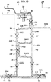
- the lower flange portion 24C is superposed on the top surface of the vehicle transverse direction end portion of the bottom plate 16, and is joined to the bottom plate 16 in the vehicle vertical direction by spot welding (refer to weld point S6 in Fig. 3 and Fig. 4 ).
- a mounting flange portion 10A that extends toward the vehicle transverse direction outer side is formed at the lower end of the vehicle transverse direction end portion of the battery case 10.
- Multiple through-holes 11 are formed in the mounting flange portion 10A so as to be lined-up in the vehicle longitudinal direction.
- the battery case 10 is fixed to the vehicle body of the electric automobile 12 by using bolts that are inserted-through these through-holes 11.
- the cross-section seen from the vehicle longitudinal direction of the inner panel 22 is bent in a rectangular wave shape, and is a cross-section of the same shape in the length direction.
- the inner panel 22 is structured by an upper side outer joining portion 22A that extends in the vehicle vertical direction as seen in the vehicle longitudinal direction, an upper side lateral wall portion 22B that extends toward the vehicle transverse direction inner side from the lower end portion of the upper side outer joining portion 22A, an upper side beam joining portion 22C that extends toward the vehicle lower side from the vehicle transverse direction inner side end portion of the upper side lateral wall portion 22B, an intermediate lateral wall portion 22D that extends toward the vehicle transverse direction outer side from the lower end portion of the upper side beam joining portion 22C, a lower side outer joining portion 22E that extends toward the vehicle lower side from the vehicle transverse direction outer side end portion of the intermediate lateral wall portion 22D, a lower side lateral wall portion 22F that extends toward the vehicle transverse direction inner side from the lower end portion of
- the upper side outer joining portion 22A and the lower side outer joining portion 22E are superposed on the vertical wall portion 24A of the outer panel 24 from the vehicle transverse direction inner side (the case inner side), and are joined to the vertical wall portion 24A in the vehicle transverse direction by spot welding (refer to the weld points S3, S4 in Fig. 4 ). Due thereto, the inner panel 22 and the outer panel 24 are joined together at the upper portion and the vertical direction intermediate portion.
- the upper side beam joining portion 22C and the lower side beam joining portion 22G are superposed on the lateral flange portions 40A of the cross beam 40 from the vehicle transverse direction outer side (the case outer side), and are joined to the lateral flange portions 40A in the vehicle transverse direction by spot welding (refer to weld points S1, S2 in Fig. 3 ).
- the lower flange portion 22H is superposed on the top surface of the bottom plate 16, and is joined to the bottom plate 16 in the vehicle vertical direction by spot welding (refer to weld point S5 in Fig. 3 and Fig. 4 ).
- the upper side lateral wall portion 22B, the intermediate lateral wall portion 22D and the lower side lateral wall portion 22F extend substantially along the vehicle horizontal direction.
- the above-described bulging portion 26 is structured by the intermediate lateral wall portion 22D, the lower side outer joining portion 22E and the lower side lateral wall portion 22F. This bulging portion 26 is formed in a substantial U-shape in cross-section whose vehicle transverse direction inner side is open as seen from the vehicle longitudinal direction.
- the upper and lower closed cross-section portions 28, 30 are formed at the upper and lower both sides of the bulging portion 26.
- the closed cross-section portion 28 at the upper side is structured by the upper side lateral wall portion 22B, the upper side beam joining portion 22C and the intermediate lateral wall portion 22D of the inner panel 22, and the vertical wall portion 24A of the outer panel 24.
- the closed cross-section portion 30 at the lower side is structured by the lower side lateral wall portion 22F and the lower side beam joining portion 22G of the inner panel 22, and the vertical wall portion 24A of the outer panel 24, and the bottom plate 16.
- the upper and lower closed cross-section portions 28, 30 are connected vertically by the lateral flange portions 40A.
- the weld points S3, S4 of spot welding that join the inner panel 22 and the outer panel 24 are disposed at positions that do not overlap the cross beams 40 as seen from the vehicle transverse direction, i.e., at positions that are offset from the cross beams 40 in the vehicle longitudinal direction (the length direction of the rectilinear portion 20A).
- the aforementioned weld points S3, S4 are offset in the vehicle longitudinal direction with respect to the cross beams 40 to the extent that the gun for spot welding does not interfere with the cross beams 40.
- the rectilinear portions 20B at the front and the rear of the side wall 20 are formed by two panels (refer to inner panel 23 and outer panel 25 that are shown in Fig. 1 ) being joined by spot welding.
- the inner panel 23 and the outer panel 25 have structures that are basically similar to those of the inner panel 22 and the outer panel 24, except that the inner panel 23 and the outer panel 25 are formed such that the length directions thereof are the vehicle transverse direction and so as to be slightly shorter than the rectilinear portions 20A at the left and the right.
- the four corner portions 20C of the side wall 20 are formed by, for example, steel plates being press-molded in circular arc shapes, and are joined to the left and right rectilinear portions 20A and to the front and rear rectilinear portions 20B (e.g., the above-described outer panels 24, 25) by means such as welding or the like.
- the present embodiment is structured such that the front and rear rectilinear portions 20B are not joined to the center beam 38, but is not limited to this. Namely, there may be a structure in which pairs of left and right flange portions are formed at the vehicle longitudinal direction end portions of the center beam 38, and these flanges and the respective inner panels 23 of the front and rear rectilinear portions 20B are joined by spot welding.
- the structure of joining the center beam 38 and the inner panel 23 and the outer panel 25 is similar to the structure of joining the inner panel 22 and the outer panel 24 and the cross beams 40.
- the center beam 38 is a supporting member that supports the front and rear rectilinear portions 20B from the case inner side.
- Fig. 5 The method of manufacturing the above-described battery case 10 is described next by using Fig. 5 through Fig. 7 .
- this manufacturing method first, in a first step, as shown in Fig. 5 , the cross beams 40 and the inner panels 22 are joined by spot welding.
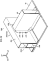
- a second step as shown in Fig. 6
- the outer panels 24 are placed on the inner panels 22 from the sides opposite the cross beams 40, and the inner panels 22 and the outer panels 24 are joined by spot welding.
- a third step as shown in Fig. 7 , the inner panels 22, the outer panels 24 and the cross beams 40 are placed on the bottom plate 16, and the inner panels 22, the outer panels 24 and the cross beams 40, and the bottom plate 16, are joined by spot welding.
- the bottom plate 16 and the left and right rectilinear portions 20A are thereby joined.
- the aforementioned inner panels 23 and the outer panels 25 are joined, and the front and rear rectilinear portions 20B are manufactured.
- the manufactured front and rear rectilinear portions 20B are placed on the bottom plate 16 to which the left and right rectilinear portions 20A have been joined as described above, and are joined to the bottom plate 16 by spot welding.
- the four corner portions 20C are joined to the left and right rectilinear portions 20A and the front and rear rectilinear portions by means such as welding or the like. Due thereto, the side wall 20 that is joined to the bottom plate 16 is completed.
- the incorporated parts such as the battery and the like are mounted to the inner side of the side wall 20 (the case inner side), and the upper lid 18 is placed on the side wall 20, and the upper lid 18 is fixed to the side wall 20 by fastening by bolts.
- the sealers 42, 44 for water blocking (refer to Fig. 3 and Fig. 4 ) are applied to the mating portion of the final end portion of the upper lid 18 and the side wall 20, and to the mating portion of the side wall 20 and the bottom plate 16. Due thereto, the battery case 10 that houses the battery, i.e., the battery pack 14, is completed.
- the battery case 10 of the above-described structure has the bottom plate 16, the side wall 20, and the cross beams 40 that are joined to the bottom plate 16 and that support the side wall 20 from the case inner side.
- the side wall 20 has the inner panels 22 to which the cross beams 40 are joined by spot welding, and the outer panels 24 that face the inner panels 22 from the sides opposite the cross beams 40.
- the upper portions of the inner panels 22 and the outer panels 24 are joined together by spot welding, and the lower end portions are joined to the bottom plate 16 by spot welding.
- the bulging portion 26, which bulges-out toward the outer panel 24 side and is joined to the outer panel 24 by spot welding is formed at the vertical direction intermediate portion of the inner panel 22.
- the closed cross-section portions 28, 30 are formed at the upper and lower both sides of the bulging portion 26 at the side wall 20, respectively.
- the weld points S3, S4 of spot welding that join the inner panel 22 and the outer panel 24 are disposed at positions that do not overlap the cross beams 40 as seen in the direction in which the inner panel 22 and the outer panel 24 face one another (the vehicle transverse direction). Therefore, at the time when the side wall 20, which forms the closed cross-section portions 28, 30, and the cross beams 40, which support the side wall 20 from the case inner side, are joined by spot welding as described above, first, the cross beams 40 and the inner panel 22 are spot welded. Then, thereafter, it suffices to spot weld the inner panel 22 and the outer panel 24 at the above-described non-overlapping positions. Therefore, there is no need to form, in the side wall 20 (the outer panel 24 and the like), openings through which a gun for spot welding is inserted.
- load e.g., the load of a side collision, hereinafter simply called "load”
- load e.g., the load of a side collision, hereinafter simply called "load”
- load e.g., the load of a side collision
- the bulging portion 26 is formed at the vertical direction intermediate portion of the inner panel 22. Namely, in a case in which a bulging portion that bulges-out toward the inner panel 22 side is formed at the vertical direction intermediate portion of the outer panel 24, a recess is formed in the surface of the outer panel 24 which surface is at the side opposite the inner panel 22 (i.e., is at the case outer side). Therefore, there is the possibility that water or foreign matter or the like will collect in this recess, but this can be avoided in the present embodiment.
- the closed cross-section portions 28, 30 that are formed at the upper and lower both sides of the bulging portion 26 respectively, are joined to the lateral flange portions 40A of the cross beams 40. Due thereto, because the upper and lower closed cross-section portions 28, 30 are connected via the lateral flange portions 40A (i.e., the cross beams 40), deformation of the side wall 20 due to load can be suppressed more efficiently.
- the upper and lower closed cross-section portions 28, 30, which are surrounded by the inner panel 22 and the outer panel 24, are formed due to the inner panel 22 being made to have a wave-shaped cross-section.
- the cross-sectional shapes of these closed cross-section portions 28, 30 are maintained, the structure is strong with respect to bending, and further, load (external force) is transmitted to the cross beams 40 via the bulging portion 26.
- load F external force
- the closed cross-section portion 28 deforms (so-called matchbox deformation) due to load F from the vehicle transverse direction outer side as shown by the dashed line in Fig. 8 , the above-described performance is no longer exhibited.
- the upper and lower closed cross-section portions 28, 30 are connected by the lateral flange portions 40A of the cross beams 40, matchbox deformation of the closed cross-section portion 28 can be suppressed without increasing the number of parts.
- the upper and lower closed cross-section portions 28, 30 are connected by the lateral flange portions 40A that extend vertically, but, even if the lateral flange portions 40A are divided vertically, the upper and lower lateral flange portions 40A that have been divided are connected to the main body portions of the cross beams 40, and therefore, the above-described matchbox deformation can be suppressed.
- the bottom plate 16, the inner panel 22, the outer panel 24 and the cross beams 40 are formed by steel plates. Therefore, the manufacturing cost can be decreased as compared with a case in which these members are formed of a light metal such as aluminum or the like or of an alloy thereof. Moreover, because the bottom plate 16 is joined to the inner panel 22, the outer panel 24 and the cross beams 40 by spot welding, the above-described respective members can be joined by only spot welding. Accordingly, manufacturing is easy.
- first comparative example 100 The partial structure of a battery case 100 for a vehicle relating to a first comparative example (hereinafter called “first comparative example 100") is shown in a cross-sectional view in Fig. 9 .
- second comparative example 200 The partial structure of a battery case 200 for a vehicle relating to a second comparative example (hereinafter called “second comparative example 200") is shown in a cross-sectional view in Fig. 10 .
- second comparative example 200 The partial structure of a battery case 200 for a vehicle relating to a second comparative example
- Fig. 10 Further, a state in which the upper lid 18 has been removed from the second comparative example 200 is shown in a perspective view in Fig. 11 , and the region indicated by letter A in Fig.
- FIG. 11 is shown in an enlarged perspective view in Fig. 12 .
- the situation at the time when a side wall 202 of the second comparative example 200 and the cross beam 40 are spot welded is shown in a cross-sectional view in Fig. 13 .
- Fig. 9 through Fig. 13 structures that are basically similar to those of the present embodiment are denoted by the same reference numerals.
- the function of protecting the incorporated battery and the like from external force of a collision or the like is expected of the battery case of a battery pack that is installed beneath the floor of a vehicle.
- the side wall that is positioned at the outer peripheral portion of the battery case hardly deforms at all even if external force is applied. Therefore, it is desirable that, when external force is applied to the side wall, the side wall transmits load to the cross beams (supporting members) without the cross-section of the side wall collapsing, and there is little bending deformation between the cross beams.
- the cross-section of a side wall 102 (the rectilinear portion 20A) be a closed cross-sectional shape, and that a lateral wall portion (bridging portion) 102A that can transmit load exist at the interior of the closed cross-section of the rectilinear portion 20A, as in the battery case 100 for a vehicle that is shown in Fig. 9 .
- the first comparative example 100 that is shown in Fig.
- FIG. 9 is an example in which the rectilinear portion 20A of the side wall 102 is manufactured by extrusion molding aluminum, but there is the problem that aluminum is expensive as compared with a steel plate.
- a performance that is similar to that of the first comparative example 100 is realized by combination with a steel plate is shown in Fig. 10 .
- the side wall 202 (the rectilinear portion 20A), which has a lateral wall portion (bridging portion) 202A that is similar to the above-described lateral wall portion 102A, is formed by combining two steel plates 204, 206 that have hat-shaped cross-sections. As shown in Fig. 11 and Fig. 12 , the cross beams 40 abut this side wall 202. At this abutting portion, it is preferable that the side wall 202 and the cross beam 40 be joined (united) by welding or the like.
- the rectilinear portion 20A and the cross beam 40 can be joined merely by spot welding, without forming work holes in the rectilinear portion 20A.
- the battery case 10 can be manufactured at a low cost, and accordingly, the cost of the electric automobile 12 can be decreased.
- the partial structure of a battery case 50 for a vehicle that relates to a second embodiment of the present disclosure is shown in a cross-sectional view in Fig. 14 .
- the cross beams 40 and the weld points S1, S2 that do not exist in the cross-section shown in Fig. 14 are shown by imaginary lines in Fig. 14 .
- the lower flange portion 24C is not provided at the lower end portion of the outer panel 24, and the lower end portion of the outer panel 24 is made integral with the bottom plate 16 (is connected integrally with the bottom plate 16).
- the bottom plate 16 and the outer panels 24 are formed integrally from a single steel plate 52 that is press-molded. This steel plate 52 is molded in the shape of a box whose upper side is open for example.
- the upper flange portion 24B of the outer panel 24 extends-out toward the vehicle transverse direction outer side from the upper end portion of the vertical wall portion 24A.
- this battery case 50 for a vehicle first, the lateral flange portions 40A of the cross beams 40 and the inner panels 22 are joined by spot welding (refer to the weld points S 1, S2 of Fig. 14 ). Next, the inner panels 22 and the cross beams 40 are placed on the bottom plate 16, and the inner panels 22 and the outer panels 24 are joined by spot welding (refer to the weld points S3, S4 in Fig. 14 ). Next, the inner panels 22 and the bottom plate 16 are joined by spot welding (refer to the weld point S5 in Fig. 14 ). In this embodiment, structures other than those described above are similar to those of the first embodiment.
- the partial structure of a battery case 60 for a vehicle that relates to a third embodiment of the present invention is shown in a cross-sectional view in Fig. 15 .
- the cross beams 40 and the weld points S1, S2, S7, S8 that do not exist in the cross-section shown in Fig. 15 are shown by imaginary lines in Fig. 15 .
- the inner panel 22 does not have the bulging portion 26, and the upper side beam joining portion 22C and the lower side beam joining portion 22G are joined in a rectilinear shape in cross-section via a lower side outer joining portion 22E'.
- a bulging portion 27, which bulges-out toward the inner panel 22 side and is joined to the inner panel 22, is formed at the vertical direction intermediate portion of the outer panel 24.
- This bulging portion 27 is formed in a substantial U-shape in cross-section whose vehicle transverse direction outer side is open, as seen from the vehicle longitudinal direction.
- the bulging portion 27 is structured by upper and lower lateral wall portions 24A1, 24A3 that extend substantially in the vehicle horizontal direction, and an inner joining portion 24A2 that vertically connects the vehicle transverse direction inner side end portions of the upper and lower lateral wall portions 24A1, 24A3.
- the inner joining portion 24A2 and the above-described lower side outer joining portion 22E' are joined in the vehicle transverse direction by spot welding.
- structures other than those described above are similar to those of the first embodiment.
- a member for suppressing deformation of the closed cross-section portion 28 due to load from the vehicle transverse direction outer side (the above-described matchbox deformation).
- a mounting bracket 62 (refer to Fig. 15 ) for mounting the battery case 60 for a vehicle to the vehicle body can be used as this additional member.
- the mounting bracket 62 is formed by, for example, a steel plate being bent into an L-shape in cross-section, and is structured by a vertical wall portion 62A that extends in the vehicle vertical direction, and an upper wall portion 62B that extends toward the vehicle transverse direction outer side from the upper end of the vertical wall portion 62A.
- the vertical wall portion 62A is joined by spot welding to the vertical wall portion 24A of the outer panel 24 (refer to the weld points S7, S8 of Fig. 15 ), and connects the upper and lower closed cross-section portions 28, 30.
- the upper wall portion 62B is superposed with the bottom surface of a frame member (e.g., a side member) of the vehicle body, and is fixed to this frame member by means such as fastening by bolts or the like.
- a frame member e.g., a side member
- the lower end portion of the inner panel 22 is made integral with the bottom plate 16.
- the lower end portion of the outer panel 24 is superposed on the lower end portion of the inner panel 22 from the vehicle transverse direction outer side, and is joined thereto by spot welding.
- FIG. 16 A partial structure of a battery case 70 for a vehicle relating to a fourth embodiment of the present invention is shown in a cross-sectional view in Fig. 16 .
- the bottom plate 16 is formed of aluminum, and the inner panel 22, the outer panel 24 and the cross beams 40 are joined to the bottom plate 16 by mechanical fastening by blind rivets R.
- blind rivets R are illustrated schematically in Fig. 16 .
- the aforementioned mechanical fastening may be fastening by bolts.
- structures other than the above are similar to those of the first embodiment.
Landscapes
- Engineering & Computer Science (AREA)
- Chemical & Material Sciences (AREA)
- Mechanical Engineering (AREA)
- Transportation (AREA)
- General Chemical & Material Sciences (AREA)
- Chemical Kinetics & Catalysis (AREA)
- Electrochemistry (AREA)
- Life Sciences & Earth Sciences (AREA)
- Sustainable Development (AREA)
- Sustainable Energy (AREA)
- Power Engineering (AREA)
- Combustion & Propulsion (AREA)
- Aviation & Aerospace Engineering (AREA)
- Inorganic Chemistry (AREA)
- Body Structure For Vehicles (AREA)
- Arrangement Or Mounting Of Propulsion Units For Vehicles (AREA)
- Battery Mounting, Suspending (AREA)
Applications Claiming Priority (1)
| Application Number | Priority Date | Filing Date | Title |
|---|---|---|---|
| JP2017222018A JP6859933B2 (ja) | 2017-11-17 | 2017-11-17 | 車両用電池ケース及びその製造方法 |
Publications (2)
| Publication Number | Publication Date |
|---|---|
| EP3486101A1 true EP3486101A1 (fr) | 2019-05-22 |
| EP3486101B1 EP3486101B1 (fr) | 2020-04-22 |
Family
ID=63720600
Family Applications (1)
| Application Number | Title | Priority Date | Filing Date |
|---|---|---|---|
| EP18198000.4A Active EP3486101B1 (fr) | 2017-11-17 | 2018-10-01 | Boîtier de batterie pour véhicule et procédé de fabrication de boîtier de batterie |
Country Status (4)
| Country | Link |
|---|---|
| US (1) | US10547039B2 (fr) |
| EP (1) | EP3486101B1 (fr) |
| JP (1) | JP6859933B2 (fr) |
| CN (1) | CN109802062B (fr) |
Cited By (4)
| Publication number | Priority date | Publication date | Assignee | Title |
|---|---|---|---|---|
| CN113119706A (zh) * | 2019-12-31 | 2021-07-16 | 奥动新能源汽车科技有限公司 | 快换支架及包含其的电动汽车 |
| EP3852187A4 (fr) * | 2019-11-19 | 2022-01-05 | Contemporary Amperex Technology Co., Limited | Bloc-batterie et véhicule |
| EP4089816A1 (fr) * | 2021-05-14 | 2022-11-16 | Flex-N-Gate Advanced Product Development, LLC | Enceinte de batterie de véhicule électrique |
| EP4084197A4 (fr) * | 2020-04-14 | 2024-07-24 | LG Energy Solution, Ltd. | Bloc-batterie et dispositif comprenant celui-ci |
Families Citing this family (41)
| Publication number | Priority date | Publication date | Assignee | Title |
|---|---|---|---|---|
| JP6891675B2 (ja) * | 2017-07-05 | 2021-06-18 | トヨタ自動車株式会社 | 電池搭載構造 |
| JP6791045B2 (ja) * | 2017-07-18 | 2020-11-25 | トヨタ自動車株式会社 | 車体前部構造 |
| JP6683777B2 (ja) * | 2018-08-28 | 2020-04-22 | 本田技研工業株式会社 | バッテリケースの固定構造 |
| KR102131535B1 (ko) | 2018-11-30 | 2020-07-07 | 주식회사 포스코 | 배터리 케이스 |
| WO2020247191A1 (fr) * | 2019-06-04 | 2020-12-10 | Shape Corp. | Traverse pour plateau de batterie de véhicule |
| FR3098022B1 (fr) * | 2019-06-28 | 2021-05-28 | Faurecia Systemes Dechappement | Batterie de stockage d’électricité et véhicule |
| JP2021077471A (ja) * | 2019-11-06 | 2021-05-20 | アイシン精機株式会社 | バッテリー冷却器 |
| CN112310541B (zh) * | 2019-11-19 | 2022-03-29 | 宁德时代新能源科技股份有限公司 | 电池包和车辆 |
| DE102019131538A1 (de) * | 2019-11-21 | 2021-05-27 | Friedrich Boysen Gmbh & Co. Kg | Batteriegehäuse für ein elektromotorisch betreibbares fahrzeug |
| HUE065577T2 (hu) * | 2019-12-24 | 2024-06-28 | Arcelormittal | Megerõsített hordozó eszköz akkumulátorcsomaghoz és eljárás megerõsített akkumulátorcsomag összeszerelésére |
| CN111063843B (zh) * | 2019-12-25 | 2023-01-24 | 北京海纳川汽车部件股份有限公司 | 车辆的电池箱和车辆 |
| KR102400037B1 (ko) * | 2020-07-06 | 2022-05-19 | 주식회사 포스코 | 배터리 케이스의 사이드 프레임 및 이의 제조방법 |
| KR102412402B1 (ko) * | 2020-07-21 | 2022-06-23 | 주식회사 포스코 | 배터리팩 프레임 결합구조 |
| CN111883711B (zh) * | 2020-08-10 | 2023-04-18 | 东时(武汉)新能源科技有限公司 | 一种电池包保护梁 |
| KR102917117B1 (ko) * | 2020-11-05 | 2026-01-22 | 주식회사 엘지에너지솔루션 | 전지 모듈 및 이를 포함하는 전지팩 |
| KR102488495B1 (ko) * | 2020-11-09 | 2023-01-13 | 주식회사 포스코 | 배터리 케이스 |
| KR102939183B1 (ko) * | 2020-11-12 | 2026-03-12 | 현대자동차주식회사 | 고전압배터리가 구비된 차체 |
| JP7133608B2 (ja) * | 2020-11-30 | 2022-09-08 | 株式会社神戸製鋼所 | 電動車両用サイドシル補強構造 |
| JP7602192B2 (ja) * | 2020-12-21 | 2024-12-18 | スズキ株式会社 | 車両用バッテリパックの構造 |
| CN112701408B (zh) * | 2020-12-25 | 2022-12-09 | 孚能科技(赣州)股份有限公司 | 箱体底盘的底板结构、箱体底盘、电池包和汽车 |
| DE102021106801A1 (de) | 2021-03-19 | 2022-09-22 | Bayerische Motoren Werke Aktiengesellschaft | Energiespeicher-Bodengruppe für einen elektrisch antreibbaren Kraftwagen |
| DE102021106800A1 (de) | 2021-03-19 | 2022-09-22 | Bayerische Motoren Werke Aktiengesellschaft | Speichergehäuse für einen elektrischen Energiespeicher eines Kraftwagens |
| JP7676880B2 (ja) * | 2021-03-30 | 2025-05-15 | 株式会社アイシン | 車両用のバッテリーケースおよび車両用のバッテリーケースの製造方法 |
| EP4350855A4 (fr) | 2021-05-24 | 2025-07-23 | G Tekt Corp | Structure de boîtier de batterie et procédé de production de structure de boîtier de batterie |
| KR20220162280A (ko) * | 2021-06-01 | 2022-12-08 | 주식회사 포스코 | 배터리 케이스의 사이드 프레임 |
| US11929517B2 (en) * | 2021-10-06 | 2024-03-12 | Ford Global Technologies, Llc | Traction battery securing assembly and method |
| WO2023114764A1 (fr) * | 2021-12-16 | 2023-06-22 | Bridgestone Americas, Inc. | Éléments structuraux à verrouillage de forme pour enceinte de batterie |
| CN118900787A (zh) * | 2022-03-22 | 2024-11-05 | 麦格纳国际公司 | 冲压的电池壳体 |
| JP7528973B2 (ja) * | 2022-03-30 | 2024-08-06 | トヨタ自動車株式会社 | 電池ケース |
| DE102022107841A1 (de) | 2022-04-01 | 2023-10-05 | Bayerische Motoren Werke Aktiengesellschaft | Energiespeichergehäuse für einen Kraftwagen |
| CN117638352A (zh) * | 2022-08-11 | 2024-03-01 | 福特全球技术公司 | 一种车辆电池保护框架和相应车辆 |
| JP7449352B1 (ja) | 2022-11-15 | 2024-03-13 | 株式会社ジーテクト | ロールフォーム成形で成形されたフレーム部品の製造方法およびフレーム部品 |
| KR102921830B1 (ko) * | 2022-12-22 | 2026-02-03 | 주식회사 성우하이텍 | 배터리 케이스용 사이드 프레임 및 이를 포함하는 배터리 케이스 |
| JP2024165329A (ja) * | 2023-05-17 | 2024-11-28 | トヨタ自動車株式会社 | 電池ケースのケース側壁 |
| CN117335072A (zh) * | 2023-10-13 | 2024-01-02 | 惠州亿纬锂能股份有限公司 | 梁结构、电池箱体及电池包 |
| KR20250085301A (ko) * | 2023-12-05 | 2025-06-12 | 삼성에스디아이 주식회사 | 셀 프레임 및 이를 포함하는 에너지 저장 장치 |
| JP2025167865A (ja) * | 2024-04-26 | 2025-11-07 | マツダ株式会社 | バッテリユニット |
| FR3163025A1 (fr) * | 2024-06-07 | 2025-12-12 | Stellantis Auto Sas | Vehicule automobile comprenant un bac de batterie qui comprend des traverses laterales soudees a des traverses inter-modules, et procede de fabrication d’un tel vehicule |
| WO2026063089A1 (fr) * | 2024-09-19 | 2026-03-26 | Jfeスチール株式会社 | Enceinte de bloc-batterie et procédé de fabrication d'enceinte de bloc-batterie |
| JP7816667B1 (ja) * | 2024-09-19 | 2026-02-18 | Jfeスチール株式会社 | バッテリケース(battery-pack enclosure)およびバッテリケースの製造方法 |
| CN118919991B (zh) * | 2024-10-10 | 2025-02-14 | 中创新航科技集团股份有限公司 | 电池装置 |
Citations (7)
| Publication number | Priority date | Publication date | Assignee | Title |
|---|---|---|---|---|
| WO2011007501A1 (fr) * | 2009-07-16 | 2011-01-20 | Nissan Motor Co., Ltd. | Bloc-batterie |
| EP2332761A1 (fr) * | 2009-12-10 | 2011-06-15 | Mitsubishi Jidosha Kogyo Kabushiki Kaisha | Boîtier de batterie |
| EP2468609A2 (fr) * | 2010-12-22 | 2012-06-27 | Tesla Motors, Inc. | Système d'absorption et de répartition d'un impact latéral utilisant un bloc-batterie intégré |
| WO2015049926A1 (fr) * | 2013-10-04 | 2015-04-09 | Toyota Jidosha Kabushiki Kaisha | Ossature de carrosserie de véhicule et structure de sous-plancher de véhicule |
| JP2015170452A (ja) | 2014-03-06 | 2015-09-28 | 三菱自動車工業株式会社 | 電動車両用の電池パック |
| US20170305251A1 (en) * | 2016-04-21 | 2017-10-26 | Toyota Jidosha Kabushiki Kaisha | Battery mounting structure for vehicle |
| WO2017207502A1 (fr) * | 2016-06-03 | 2017-12-07 | Thyssenkrupp Steel Europe Ag | Logement de batterie et utilisation d'un logement de batterie |
Family Cites Families (38)
| Publication number | Priority date | Publication date | Assignee | Title |
|---|---|---|---|---|
| US5501289A (en) * | 1993-01-22 | 1996-03-26 | Nissan Motor Co., Ltd. | Floor structure of electric vehicle |
| US6085854A (en) * | 1994-12-13 | 2000-07-11 | Nissan Motor Co., Ltd. | Battery frame structure for electric motorcar |
| JP3970684B2 (ja) * | 2002-05-21 | 2007-09-05 | 日産自動車株式会社 | 二次電池モジュール |
| JP5029263B2 (ja) * | 2007-09-28 | 2012-09-19 | 三菱自動車工業株式会社 | 電気自動車 |
| JP5151363B2 (ja) * | 2007-09-28 | 2013-02-27 | 三菱自動車工業株式会社 | 電気自動車用バッテリケース |
| JP5098544B2 (ja) * | 2007-09-28 | 2012-12-12 | 三菱自動車工業株式会社 | バッテリユニット |
| JP5092657B2 (ja) * | 2007-09-28 | 2012-12-05 | 三菱自動車工業株式会社 | バッテリユニット |
| JP4386131B2 (ja) * | 2007-12-05 | 2009-12-16 | 三菱自動車工業株式会社 | 電気自動車 |
| JP4306783B2 (ja) * | 2007-12-14 | 2009-08-05 | 三菱自動車工業株式会社 | 電気自動車のバッテリユニット取付構造 |
| JP4946969B2 (ja) * | 2008-05-16 | 2012-06-06 | トヨタ自動車株式会社 | 電源装置の保護構造 |
| US8479858B2 (en) * | 2009-12-03 | 2013-07-09 | Mazda Motor Corporation | Battery arrangement structure of vehicle |
| JP5654039B2 (ja) * | 2010-11-10 | 2015-01-14 | 本田技研工業株式会社 | 自動車のフロア構造 |
| US8336658B2 (en) * | 2010-12-22 | 2012-12-25 | Tesla Motors, Inc. | Augmented vehicle seat mount |
| WO2012086297A1 (fr) * | 2010-12-24 | 2012-06-28 | 本田技研工業株式会社 | Structure de carrosserie d'automobile |
| JP5513445B2 (ja) * | 2011-06-08 | 2014-06-04 | 本田技研工業株式会社 | 車両用電源装置 |
| JP5375886B2 (ja) * | 2011-07-26 | 2013-12-25 | トヨタ自動車株式会社 | 自動車の電池保護構造 |
| JP5824997B2 (ja) * | 2011-09-14 | 2015-12-02 | トヨタ自動車株式会社 | 車両用電池搭載構造 |
| JP5734453B2 (ja) * | 2011-11-14 | 2015-06-17 | 本田技研工業株式会社 | バッテリの車載構造 |
| JP5887883B2 (ja) * | 2011-11-29 | 2016-03-16 | トヨタ自動車株式会社 | 車両用電池搭載構造 |
| JP5552109B2 (ja) * | 2011-12-27 | 2014-07-16 | 株式会社神戸製鋼所 | 車載用バッテリートレイおよび車載用バッテリーフレーム |
| JP5880086B2 (ja) * | 2012-01-31 | 2016-03-08 | 三菱自動車工業株式会社 | 電池容器 |
| DE102012100977B3 (de) | 2012-02-07 | 2013-07-18 | Benteler Automobiltechnik Gmbh | Energiespeichergefäß für ein Kraftfahrzeug mit Elektro- oder Hybridantrieb |
| US8608230B2 (en) * | 2012-04-13 | 2013-12-17 | Toyota Motor Engineering & Manufacturing North America, Inc. | Localized energy dissipation structures for vehicles |
| JP6020958B2 (ja) * | 2012-07-13 | 2016-11-02 | 三菱自動車工業株式会社 | 電池パックトレー |
| US9281505B2 (en) * | 2012-10-16 | 2016-03-08 | Toyota Jidosha Kabushiki Kaisha | Battery mounting structure for vehicle |
| CN104919620B (zh) * | 2013-01-11 | 2017-07-11 | 双叶产业株式会社 | 电池盒 |
| JP5930123B2 (ja) * | 2013-12-02 | 2016-06-08 | トヨタ自動車株式会社 | 車両用電池搭載構造 |
| JP5846193B2 (ja) * | 2013-12-25 | 2016-01-20 | トヨタ自動車株式会社 | 車両用電池搭載構造 |
| JP5971235B2 (ja) * | 2013-12-25 | 2016-08-17 | トヨタ自動車株式会社 | バッテリフレーム及び車両用電池搭載構造 |
| JP5900481B2 (ja) * | 2013-12-25 | 2016-04-06 | トヨタ自動車株式会社 | 車両パネル構造 |
| JP5870992B2 (ja) * | 2013-12-25 | 2016-03-01 | トヨタ自動車株式会社 | 車両用電池搭載構造 |
| JP6344270B2 (ja) * | 2015-03-06 | 2018-06-20 | トヨタ自動車株式会社 | バッテリユニット搭載構造 |
| JPWO2017073416A1 (ja) * | 2015-10-30 | 2018-08-30 | 日立オートモティブシステムズ株式会社 | 蓄電装置 |
| US9821852B2 (en) * | 2016-02-03 | 2017-11-21 | Ford Global Technologies Llc | Pressurized air insert for side impacts |
| JP6520808B2 (ja) * | 2016-04-21 | 2019-05-29 | トヨタ自動車株式会社 | 車両のバッテリ搭載構造 |
| CN206076313U (zh) * | 2016-08-29 | 2017-04-05 | 北京普莱德新能源电池科技有限公司 | 一种新型动力电池包箱体 |
| JP6555236B2 (ja) * | 2016-11-30 | 2019-08-07 | トヨタ自動車株式会社 | 車体下部構造 |
| CN206441787U (zh) * | 2016-12-29 | 2017-08-25 | 国联汽车动力电池研究院有限责任公司 | 一种电动汽车电池箱 |
-
2017
- 2017-11-17 JP JP2017222018A patent/JP6859933B2/ja active Active
-
2018
- 2018-09-25 CN CN201811112124.3A patent/CN109802062B/zh active Active
- 2018-09-26 US US16/142,118 patent/US10547039B2/en active Active
- 2018-10-01 EP EP18198000.4A patent/EP3486101B1/fr active Active
Patent Citations (7)
| Publication number | Priority date | Publication date | Assignee | Title |
|---|---|---|---|---|
| WO2011007501A1 (fr) * | 2009-07-16 | 2011-01-20 | Nissan Motor Co., Ltd. | Bloc-batterie |
| EP2332761A1 (fr) * | 2009-12-10 | 2011-06-15 | Mitsubishi Jidosha Kogyo Kabushiki Kaisha | Boîtier de batterie |
| EP2468609A2 (fr) * | 2010-12-22 | 2012-06-27 | Tesla Motors, Inc. | Système d'absorption et de répartition d'un impact latéral utilisant un bloc-batterie intégré |
| WO2015049926A1 (fr) * | 2013-10-04 | 2015-04-09 | Toyota Jidosha Kabushiki Kaisha | Ossature de carrosserie de véhicule et structure de sous-plancher de véhicule |
| JP2015170452A (ja) | 2014-03-06 | 2015-09-28 | 三菱自動車工業株式会社 | 電動車両用の電池パック |
| US20170305251A1 (en) * | 2016-04-21 | 2017-10-26 | Toyota Jidosha Kabushiki Kaisha | Battery mounting structure for vehicle |
| WO2017207502A1 (fr) * | 2016-06-03 | 2017-12-07 | Thyssenkrupp Steel Europe Ag | Logement de batterie et utilisation d'un logement de batterie |
Cited By (8)
| Publication number | Priority date | Publication date | Assignee | Title |
|---|---|---|---|---|
| EP3852187A4 (fr) * | 2019-11-19 | 2022-01-05 | Contemporary Amperex Technology Co., Limited | Bloc-batterie et véhicule |
| US11329347B2 (en) | 2019-11-19 | 2022-05-10 | Contemporary Amperex Technology Co., Limited | Battery pack and vehicle |
| CN113119706A (zh) * | 2019-12-31 | 2021-07-16 | 奥动新能源汽车科技有限公司 | 快换支架及包含其的电动汽车 |
| EP4084197A4 (fr) * | 2020-04-14 | 2024-07-24 | LG Energy Solution, Ltd. | Bloc-batterie et dispositif comprenant celui-ci |
| US12512548B2 (en) | 2020-04-14 | 2025-12-30 | Lg Energy Solution, Ltd. | Battery pack and device including the same |
| EP4089816A1 (fr) * | 2021-05-14 | 2022-11-16 | Flex-N-Gate Advanced Product Development, LLC | Enceinte de batterie de véhicule électrique |
| US20220367957A1 (en) * | 2021-05-14 | 2022-11-17 | Flex-N-Gate Advanced Product Development, Llc | Electric vehicle battery enclosure |
| US12362423B2 (en) * | 2021-05-14 | 2025-07-15 | Flex-N-Gate Advanced Product Development, Llc | Electric vehicle battery enclosure |
Also Published As
| Publication number | Publication date |
|---|---|
| JP2019096385A (ja) | 2019-06-20 |
| US20190157642A1 (en) | 2019-05-23 |
| CN109802062B (zh) | 2021-08-27 |
| CN109802062A (zh) | 2019-05-24 |
| JP6859933B2 (ja) | 2021-04-14 |
| EP3486101B1 (fr) | 2020-04-22 |
| US10547039B2 (en) | 2020-01-28 |
Similar Documents
| Publication | Publication Date | Title |
|---|---|---|
| EP3486101B1 (fr) | Boîtier de batterie pour véhicule et procédé de fabrication de boîtier de batterie | |
| US10597081B2 (en) | Vehicle front portion structure | |
| CN110588800B (zh) | 车身下部结构 | |
| US10766537B2 (en) | Vehicle side portion structure | |
| EP3412486B1 (fr) | Structure de montage de batterie | |
| US9956861B2 (en) | Framework structure of body-on-frame vehicle | |
| JP6866784B2 (ja) | 車体下部構造 | |
| JP6215905B2 (ja) | 車体後部構造 | |
| EP3647163A1 (fr) | Structure de partie avant de véhicule | |
| CN110091928B (zh) | 车辆的地板构造 | |
| EP2689972B1 (fr) | Structure de section d'extrémité de véhicule | |
| US20200198453A1 (en) | Battery housing for a vehicle battery and chassis for an electric vehicle | |
| US11027780B2 (en) | Vehicle front portion structure | |
| JP7535249B2 (ja) | 車両用バッテリパックの固定構造 | |
| WO2022249782A1 (fr) | Structure de boîtier de batterie et procédé de production de structure de boîtier de batterie | |
| JP5157833B2 (ja) | 車体前部構造 | |
| US20210221441A1 (en) | Vehicle body lower structure | |
| JP5957721B2 (ja) | 車両構造 | |
| JP2022097816A (ja) | 車両用バッテリパックの構造 | |
| JP7306544B2 (ja) | 車両下部構造 | |
| WO2024225159A1 (fr) | Boîtier de batterie | |
| CN115566345A (zh) | 用于电动车辆的轻量化电池箱 | |
| EP4574629A1 (fr) | Structure de carrosserie inférieure de véhicule | |
| JP2022097815A (ja) | 車両用バッテリパックの構造 | |
| JP7662817B2 (ja) | 車両フロアのための湾曲クロスメンバ |
Legal Events
| Date | Code | Title | Description |
|---|---|---|---|
| PUAI | Public reference made under article 153(3) epc to a published international application that has entered the european phase |
Free format text: ORIGINAL CODE: 0009012 |
|
| STAA | Information on the status of an ep patent application or granted ep patent |
Free format text: STATUS: REQUEST FOR EXAMINATION WAS MADE |
|
| 17P | Request for examination filed |
Effective date: 20181001 |
|
| AK | Designated contracting states |
Kind code of ref document: A1 Designated state(s): AL AT BE BG CH CY CZ DE DK EE ES FI FR GB GR HR HU IE IS IT LI LT LU LV MC MK MT NL NO PL PT RO RS SE SI SK SM TR |
|
| AX | Request for extension of the european patent |
Extension state: BA ME |
|
| GRAP | Despatch of communication of intention to grant a patent |
Free format text: ORIGINAL CODE: EPIDOSNIGR1 |
|
| STAA | Information on the status of an ep patent application or granted ep patent |
Free format text: STATUS: GRANT OF PATENT IS INTENDED |
|
| INTG | Intention to grant announced |
Effective date: 20200121 |
|
| RIN1 | Information on inventor provided before grant (corrected) |
Inventor name: TOYOTA, MASARU |
|
| GRAS | Grant fee paid |
Free format text: ORIGINAL CODE: EPIDOSNIGR3 |
|
| GRAA | (expected) grant |
Free format text: ORIGINAL CODE: 0009210 |
|
| STAA | Information on the status of an ep patent application or granted ep patent |
Free format text: STATUS: THE PATENT HAS BEEN GRANTED |
|
| AK | Designated contracting states |
Kind code of ref document: B1 Designated state(s): AL AT BE BG CH CY CZ DE DK EE ES FI FR GB GR HR HU IE IS IT LI LT LU LV MC MK MT NL NO PL PT RO RS SE SI SK SM TR |
|
| REG | Reference to a national code |
Ref country code: CH Ref legal event code: EP |
|
| REG | Reference to a national code |
Ref country code: IE Ref legal event code: FG4D |
|
| REG | Reference to a national code |
Ref country code: DE Ref legal event code: R096 Ref document number: 602018003972 Country of ref document: DE |
|
| REG | Reference to a national code |
Ref country code: AT Ref legal event code: REF Ref document number: 1259636 Country of ref document: AT Kind code of ref document: T Effective date: 20200515 |
|
| REG | Reference to a national code |
Ref country code: LT Ref legal event code: MG4D |
|
| REG | Reference to a national code |
Ref country code: NL Ref legal event code: MP Effective date: 20200422 |
|
| PG25 | Lapsed in a contracting state [announced via postgrant information from national office to epo] |
Ref country code: PT Free format text: LAPSE BECAUSE OF FAILURE TO SUBMIT A TRANSLATION OF THE DESCRIPTION OR TO PAY THE FEE WITHIN THE PRESCRIBED TIME-LIMIT Effective date: 20200824 Ref country code: NO Free format text: LAPSE BECAUSE OF FAILURE TO SUBMIT A TRANSLATION OF THE DESCRIPTION OR TO PAY THE FEE WITHIN THE PRESCRIBED TIME-LIMIT Effective date: 20200722 Ref country code: GR Free format text: LAPSE BECAUSE OF FAILURE TO SUBMIT A TRANSLATION OF THE DESCRIPTION OR TO PAY THE FEE WITHIN THE PRESCRIBED TIME-LIMIT Effective date: 20200723 Ref country code: NL Free format text: LAPSE BECAUSE OF FAILURE TO SUBMIT A TRANSLATION OF THE DESCRIPTION OR TO PAY THE FEE WITHIN THE PRESCRIBED TIME-LIMIT Effective date: 20200422 Ref country code: LT Free format text: LAPSE BECAUSE OF FAILURE TO SUBMIT A TRANSLATION OF THE DESCRIPTION OR TO PAY THE FEE WITHIN THE PRESCRIBED TIME-LIMIT Effective date: 20200422 Ref country code: SE Free format text: LAPSE BECAUSE OF FAILURE TO SUBMIT A TRANSLATION OF THE DESCRIPTION OR TO PAY THE FEE WITHIN THE PRESCRIBED TIME-LIMIT Effective date: 20200422 Ref country code: IS Free format text: LAPSE BECAUSE OF FAILURE TO SUBMIT A TRANSLATION OF THE DESCRIPTION OR TO PAY THE FEE WITHIN THE PRESCRIBED TIME-LIMIT Effective date: 20200822 Ref country code: FI Free format text: LAPSE BECAUSE OF FAILURE TO SUBMIT A TRANSLATION OF THE DESCRIPTION OR TO PAY THE FEE WITHIN THE PRESCRIBED TIME-LIMIT Effective date: 20200422 |
|
| REG | Reference to a national code |
Ref country code: AT Ref legal event code: MK05 Ref document number: 1259636 Country of ref document: AT Kind code of ref document: T Effective date: 20200422 |
|
| PG25 | Lapsed in a contracting state [announced via postgrant information from national office to epo] |
Ref country code: RS Free format text: LAPSE BECAUSE OF FAILURE TO SUBMIT A TRANSLATION OF THE DESCRIPTION OR TO PAY THE FEE WITHIN THE PRESCRIBED TIME-LIMIT Effective date: 20200422 Ref country code: HR Free format text: LAPSE BECAUSE OF FAILURE TO SUBMIT A TRANSLATION OF THE DESCRIPTION OR TO PAY THE FEE WITHIN THE PRESCRIBED TIME-LIMIT Effective date: 20200422 Ref country code: LV Free format text: LAPSE BECAUSE OF FAILURE TO SUBMIT A TRANSLATION OF THE DESCRIPTION OR TO PAY THE FEE WITHIN THE PRESCRIBED TIME-LIMIT Effective date: 20200422 Ref country code: BG Free format text: LAPSE BECAUSE OF FAILURE TO SUBMIT A TRANSLATION OF THE DESCRIPTION OR TO PAY THE FEE WITHIN THE PRESCRIBED TIME-LIMIT Effective date: 20200722 |
|
| PG25 | Lapsed in a contracting state [announced via postgrant information from national office to epo] |
Ref country code: AL Free format text: LAPSE BECAUSE OF FAILURE TO SUBMIT A TRANSLATION OF THE DESCRIPTION OR TO PAY THE FEE WITHIN THE PRESCRIBED TIME-LIMIT Effective date: 20200422 |
|
| REG | Reference to a national code |
Ref country code: DE Ref legal event code: R097 Ref document number: 602018003972 Country of ref document: DE |
|
| PG25 | Lapsed in a contracting state [announced via postgrant information from national office to epo] |
Ref country code: CZ Free format text: LAPSE BECAUSE OF FAILURE TO SUBMIT A TRANSLATION OF THE DESCRIPTION OR TO PAY THE FEE WITHIN THE PRESCRIBED TIME-LIMIT Effective date: 20200422 Ref country code: RO Free format text: LAPSE BECAUSE OF FAILURE TO SUBMIT A TRANSLATION OF THE DESCRIPTION OR TO PAY THE FEE WITHIN THE PRESCRIBED TIME-LIMIT Effective date: 20200422 Ref country code: ES Free format text: LAPSE BECAUSE OF FAILURE TO SUBMIT A TRANSLATION OF THE DESCRIPTION OR TO PAY THE FEE WITHIN THE PRESCRIBED TIME-LIMIT Effective date: 20200422 Ref country code: EE Free format text: LAPSE BECAUSE OF FAILURE TO SUBMIT A TRANSLATION OF THE DESCRIPTION OR TO PAY THE FEE WITHIN THE PRESCRIBED TIME-LIMIT Effective date: 20200422 Ref country code: SM Free format text: LAPSE BECAUSE OF FAILURE TO SUBMIT A TRANSLATION OF THE DESCRIPTION OR TO PAY THE FEE WITHIN THE PRESCRIBED TIME-LIMIT Effective date: 20200422 Ref country code: IT Free format text: LAPSE BECAUSE OF FAILURE TO SUBMIT A TRANSLATION OF THE DESCRIPTION OR TO PAY THE FEE WITHIN THE PRESCRIBED TIME-LIMIT Effective date: 20200422 Ref country code: AT Free format text: LAPSE BECAUSE OF FAILURE TO SUBMIT A TRANSLATION OF THE DESCRIPTION OR TO PAY THE FEE WITHIN THE PRESCRIBED TIME-LIMIT Effective date: 20200422 Ref country code: DK Free format text: LAPSE BECAUSE OF FAILURE TO SUBMIT A TRANSLATION OF THE DESCRIPTION OR TO PAY THE FEE WITHIN THE PRESCRIBED TIME-LIMIT Effective date: 20200422 |
|
| PG25 | Lapsed in a contracting state [announced via postgrant information from national office to epo] |
Ref country code: SK Free format text: LAPSE BECAUSE OF FAILURE TO SUBMIT A TRANSLATION OF THE DESCRIPTION OR TO PAY THE FEE WITHIN THE PRESCRIBED TIME-LIMIT Effective date: 20200422 Ref country code: PL Free format text: LAPSE BECAUSE OF FAILURE TO SUBMIT A TRANSLATION OF THE DESCRIPTION OR TO PAY THE FEE WITHIN THE PRESCRIBED TIME-LIMIT Effective date: 20200422 |
|
| PLBE | No opposition filed within time limit |
Free format text: ORIGINAL CODE: 0009261 |
|
| STAA | Information on the status of an ep patent application or granted ep patent |
Free format text: STATUS: NO OPPOSITION FILED WITHIN TIME LIMIT |
|
| 26N | No opposition filed |
Effective date: 20210125 |
|
| PG25 | Lapsed in a contracting state [announced via postgrant information from national office to epo] |
Ref country code: SI Free format text: LAPSE BECAUSE OF FAILURE TO SUBMIT A TRANSLATION OF THE DESCRIPTION OR TO PAY THE FEE WITHIN THE PRESCRIBED TIME-LIMIT Effective date: 20200422 |
|
| PG25 | Lapsed in a contracting state [announced via postgrant information from national office to epo] |
Ref country code: MC Free format text: LAPSE BECAUSE OF FAILURE TO SUBMIT A TRANSLATION OF THE DESCRIPTION OR TO PAY THE FEE WITHIN THE PRESCRIBED TIME-LIMIT Effective date: 20200422 Ref country code: LU Free format text: LAPSE BECAUSE OF NON-PAYMENT OF DUE FEES Effective date: 20201001 |
|
| REG | Reference to a national code |
Ref country code: BE Ref legal event code: MM Effective date: 20201031 |
|
| PG25 | Lapsed in a contracting state [announced via postgrant information from national office to epo] |
Ref country code: BE Free format text: LAPSE BECAUSE OF NON-PAYMENT OF DUE FEES Effective date: 20201031 |
|
| PG25 | Lapsed in a contracting state [announced via postgrant information from national office to epo] |
Ref country code: IE Free format text: LAPSE BECAUSE OF NON-PAYMENT OF DUE FEES Effective date: 20201001 |
|
| PG25 | Lapsed in a contracting state [announced via postgrant information from national office to epo] |
Ref country code: TR Free format text: LAPSE BECAUSE OF FAILURE TO SUBMIT A TRANSLATION OF THE DESCRIPTION OR TO PAY THE FEE WITHIN THE PRESCRIBED TIME-LIMIT Effective date: 20200422 Ref country code: MT Free format text: LAPSE BECAUSE OF FAILURE TO SUBMIT A TRANSLATION OF THE DESCRIPTION OR TO PAY THE FEE WITHIN THE PRESCRIBED TIME-LIMIT Effective date: 20200422 Ref country code: CY Free format text: LAPSE BECAUSE OF FAILURE TO SUBMIT A TRANSLATION OF THE DESCRIPTION OR TO PAY THE FEE WITHIN THE PRESCRIBED TIME-LIMIT Effective date: 20200422 |
|
| REG | Reference to a national code |
Ref country code: CH Ref legal event code: PL |
|
| PG25 | Lapsed in a contracting state [announced via postgrant information from national office to epo] |
Ref country code: MK Free format text: LAPSE BECAUSE OF FAILURE TO SUBMIT A TRANSLATION OF THE DESCRIPTION OR TO PAY THE FEE WITHIN THE PRESCRIBED TIME-LIMIT Effective date: 20200422 |
|
| PG25 | Lapsed in a contracting state [announced via postgrant information from national office to epo] |
Ref country code: LI Free format text: LAPSE BECAUSE OF NON-PAYMENT OF DUE FEES Effective date: 20211031 Ref country code: CH Free format text: LAPSE BECAUSE OF NON-PAYMENT OF DUE FEES Effective date: 20211031 |
|
| P01 | Opt-out of the competence of the unified patent court (upc) registered |
Effective date: 20230427 |
|
| REG | Reference to a national code |
Ref country code: DE Ref legal event code: R084 Ref document number: 602018003972 Country of ref document: DE |
|
| REG | Reference to a national code |
Ref country code: GB Ref legal event code: 746 Effective date: 20230825 |
|
| PGFP | Annual fee paid to national office [announced via postgrant information from national office to epo] |
Ref country code: GB Payment date: 20250828 Year of fee payment: 8 |
|
| PGFP | Annual fee paid to national office [announced via postgrant information from national office to epo] |
Ref country code: FR Payment date: 20250908 Year of fee payment: 8 |
|
| PGFP | Annual fee paid to national office [announced via postgrant information from national office to epo] |
Ref country code: DE Payment date: 20250902 Year of fee payment: 8 |