EP3486182A1 - Rotationskopf mit längsbeweglichem faltkanal - Google Patents
Rotationskopf mit längsbeweglichem faltkanal Download PDFInfo
- Publication number
- EP3486182A1 EP3486182A1 EP18188013.9A EP18188013A EP3486182A1 EP 3486182 A1 EP3486182 A1 EP 3486182A1 EP 18188013 A EP18188013 A EP 18188013A EP 3486182 A1 EP3486182 A1 EP 3486182A1
- Authority
- EP
- European Patent Office
- Prior art keywords
- holding
- folding
- product
- rotary head
- head
- Prior art date
- Legal status (The legal status is an assumption and is not a legal conclusion. Google has not performed a legal analysis and makes no representation as to the accuracy of the status listed.)
- Granted
Links
Images





Classifications
-
- B—PERFORMING OPERATIONS; TRANSPORTING
- B65—CONVEYING; PACKING; STORING; HANDLING THIN OR FILAMENTARY MATERIAL
- B65B—MACHINES, APPARATUS OR DEVICES FOR, OR METHODS OF, PACKAGING ARTICLES OR MATERIALS; UNPACKING
- B65B25/00—Packaging other articles presenting special problems
- B65B25/005—Packaging other articles presenting special problems packaging of confectionery
-
- B—PERFORMING OPERATIONS; TRANSPORTING
- B65—CONVEYING; PACKING; STORING; HANDLING THIN OR FILAMENTARY MATERIAL
- B65B—MACHINES, APPARATUS OR DEVICES FOR, OR METHODS OF, PACKAGING ARTICLES OR MATERIALS; UNPACKING
- B65B11/00—Wrapping, e.g. partially or wholly enclosing, articles or quantities of material, in strips, sheets or blanks, of flexible material
- B65B11/06—Wrapping articles, or quantities of material, by conveying wrapper and contents in common defined paths
- B65B11/28—Wrapping articles, or quantities of material, by conveying wrapper and contents in common defined paths in a curved path, e.g. on rotary tables or turrets
-
- B—PERFORMING OPERATIONS; TRANSPORTING
- B65—CONVEYING; PACKING; STORING; HANDLING THIN OR FILAMENTARY MATERIAL
- B65B—MACHINES, APPARATUS OR DEVICES FOR, OR METHODS OF, PACKAGING ARTICLES OR MATERIALS; UNPACKING
- B65B11/00—Wrapping, e.g. partially or wholly enclosing, articles or quantities of material, in strips, sheets or blanks, of flexible material
- B65B11/54—Wrapping by causing the wrapper to embrace one end and all sides of the contents, and closing the wrapper onto the opposite end by forming regular or irregular pleats
-
- B—PERFORMING OPERATIONS; TRANSPORTING
- B65—CONVEYING; PACKING; STORING; HANDLING THIN OR FILAMENTARY MATERIAL
- B65B—MACHINES, APPARATUS OR DEVICES FOR, OR METHODS OF, PACKAGING ARTICLES OR MATERIALS; UNPACKING
- B65B49/00—Devices for folding or bending wrappers around contents
- B65B49/06—Resilient folders, e.g. brushes, diaphragms
-
- B—PERFORMING OPERATIONS; TRANSPORTING
- B65—CONVEYING; PACKING; STORING; HANDLING THIN OR FILAMENTARY MATERIAL
- B65B—MACHINES, APPARATUS OR DEVICES FOR, OR METHODS OF, PACKAGING ARTICLES OR MATERIALS; UNPACKING
- B65B49/00—Devices for folding or bending wrappers around contents
- B65B49/08—Reciprocating or oscillating folders
Definitions
- the present invention relates to a rotary head for a packaging machine, in particular for small-sized confectionery products, comprising a plurality of holding jaw pairs and a plurality of divisible folding channels (which are opened and closed in operation), wherein each jaw pair is associated with a divisible folding channel.
- Such a rotary head is e.g. from the EMC packaging machine of Theeberg Pactec GmbH.
- This machine comprises a rapier head, which assigns a packaging material blank to a product and then transfers the product together with the packaging material blank to a packing head (rotary head).
- the packing head has a splittable brush ring, which is opened prior to the transfer of the packaged product and closed again before transfer from the rapier head to the packing head and through which the product is pressed together with the packaging blank.
- both the gripper head and the packing head on ram which pinch the product together with the packaging blank between the top and bottom of the product and move together through the brush ring.
- the packaging blanks attaches to the side of the product.
- both the holding jaws of the gripper head and the holding jaws of the packing head are open.
- the holding jaw pair of the packing head is located radially inside the brush ring.
- the final folding of the packaging blank on the product is then carried out on the packing head.
- the transfer process by means of the stamp on the rapier head and the packing head requires long stamp paths and is therefore technically complex.
- a brush ring is just a special form of a folding channel. In general, these folding channels can also specify a precise application process to the product by means of certain geometric inner contours. A brush ring smoothes along the sides of the product.
- the invention provides that the divisible, moving in operation from an opening into a closed position folding channel for exerting a folding movement is arranged longitudinally movable on the rotary head.
- the arrangement of folding channels on the rotary head itself is known; but not as a divisible, ie in operation opening and closing, and longitudinally movable folding channel, so that, for example, a folding of the folding channel is also possible from a radially outer position to a radially inner position around the holding portion of the holding jaws around. In this case, it is also possible to use linear or almost linear movements which deviate from the direction of rotation of the rotary head.
- the exercise of the folding movement by the divisible, movable from an opening to a closed position folding channel also simplifies the design of the associated holding means which hold the product together with the packaging blank in position during this process.
- This process can be carried out either by holding means which are arranged entirely on the rotary head, or at least partially access it from the outside.
- the kinematics for such holding means components is simplified, because the product does not have to be actively moved together with the packaging blank through the folding channel, but mainly moves the folding channel along the product.
- the divisible folding channel can be arranged to be longitudinally movable on the rotary head radially to the axis of rotation of the rotary head for exerting the folding movement.
- the feasibility of the individual parts of the folding channel makes particularly advantageous because it can be moved from one side to the other side of the holding portion of the holding jaw pair, even if the holding jaw pair is designed for pressing on the side regions of the product.
- the divisible folding channel may be a separable brush ring.
- the divisible folding channel can be driven by means of a coupling gear radially to the axis of rotation for exerting the folding movement, wherein the coupling gear is part of the rotary head.
- a coupling gear provides a simple and efficient and space-saving means to exercise the movement of the divisible folding channel.
- the actuation of the linkage can e.g. via cams and curved paths, so that the corresponding movement can be exercised even with a rapidly rotating rotary head.
- the coupling mechanism can be configured driving the divisible folding channel both for performing the folding movement as well as for exerting the opening and closing movement of the folding channel. Both movements are therefore carried out by one and the same drive, resulting in a cost and energy savings.
- the opening and closing movement can be effected by means of at least radially displaceable pivot axes of the linkage.
- the pivot axes can also be moved tangentially.
- only a part or only one of the pivot axes of the linkage must perform this function, while usually take the Basisschwenkachsen on the rotary head a fixed position.
- the holding jaw pair may be designed to hold the side regions of a product partially surrounded by a packaging blank, wherein each holding jaw pair is associated with a holding punch which forms a stop for the radially inner side of the product partially surrounded by the packaging blank. Accordingly, there is no necessity for the holding punch to be longitudinally movably mounted on the rotary head. This needs only as a stop too Act.
- the holding stamp on a buffer function for example, is spring-moving, so that a predetermined holding force is not exceeded. This holding stamp then also specifies the radial position of the product together with the packaging blank on the rotary head.
- the invention relates to a device with a rotary head according to one of claims 1 to 6 and a holding jaw device.
- the holding jaw device may have at least one holding jaw, which is synchronized with the rotation of the rotary head in the direction of an associated holding temple of the rotary head is movable so that holds the holding jaw along with the holding stamp partially surrounded by the packaging blank product and the associated holding jaw pair and the associated folding channel are controlled such that the holding jaw pair during this holding operation by the holding jaw and the holding punch opens (ie the path for the folding channel freed) and the folding channel exerts the folding movement.
- the product together with the packaging blank can thus be transported on the rotating head of the holding jaw pair to be released over a certain range, so that the folding movement of the folding channel can be performed, and then be taken again by the holding jaw pair for further transport.
- the product with the packaging blank thus has substantially a radially equal distance from the axis of rotation of the rotary head, while the folding movement of the folding channel is exerted. This also allows radially shorter holding jaws, which protrude less far, because the folding channel moves itself on the rotary head.
- the application step is carried out while the second holding device holds the product and the associated packaging means blank and the first holding device does not interfere with the attachment step of the divisible folding channel.
- the method may further include the step of: Returning the product with the packaging blank to the first holding device.
- the first holding device thus assumes the general transport of the product with the packaging blank by the rotary head, while only for the application step, a transfer to the second holding device. As a result, then the further folding operations can be performed.
- the following step can be provided: opening the divisible folding channel after the application step.
- opening the divisible folding channel By opening the divisible folding channel, the path can be released for the first holding device, which can take the product and the packaging blank. This simplifies the movements.
- this is not mandatory, because an opening of the divisible folding channel can also take place during or after the closing of the first holding device.
- the opened folding channel is moved to exert a return movement to the starting position of the folding movement counter to the Faltschulscardi on the rotary head when the product with the packaging blank was returned to the first holding device.
- a relatively long rotational travel of the rotary head is available until the folding channel has to perform its next application step.
- the method further comprises the following step: closing the folding channel prior to applying the folding motion.
- FIG Fig. 1 A packaging device 1 for in particular small-sized confectionery products is shown schematically in FIG Fig. 1 shown.
- the packaging machine 1 essentially comprises a linear conveyor 2 for feeding the products P, a receiving head 3 for receiving the products P and passing them to a rapier head 4 for allocating a packaging blank Z to the product P, a packing head 5 for applying the relevant packaging steps and a dispensing head 6 for receiving and delivering the finished packaged products P 1 and a feed unit 7 for packaging material.
- the packaging material supply unit 7 comprises two stations for packaging material rolls 8 and 9, wherein a first packaging material roll 8 expires and the second packaging material roll 9 is prepared and switched on as soon as the first packaging material roll 8 is empty.
- the pickup head 3, the gripper head 4, the packing head 5 and the dispensing head 6 are each designed as rotary heads and provided with corresponding holding jaw pairs for transporting the product P and optionally the packaging blank Z.
- a plurality of holding jaw pairs are arranged evenly distributed on the peripheries of the rotary heads.
- the gripper head 4 assigns a product P to a packaging means blank Z, so that the packaging means blank Z is guided around the product in an L-shape.
- the packing head 5 of the packaging blank Z is placed in a U-shape to the product P.
- the holding jaw pairs of the gripper head 4 and of the packing head 5 as a rule have an opening and closing direction rotated by 90 ° with respect to one another, so that their holding regions can intermesh for transferring the product P together with the packaging means blank Z.
- the invention is mainly concerned with the novel design of the packing head 5. Its structure and operation will now be based on the Figures 2-9 explained in more detail. For simplicity and clarity, only one station of the packing head 5 is provided with the devices explained in more detail below. These are of course available at each of these stations 12 of the packing head 5. In addition, for better clarity, the packaging blank Z is not shown, but only the product P alone.
- the packing head 5 is designed as a kind of rotary drum and rotates counterclockwise. In a recess 10 of the drum 11 are different in a star shape Stations 12 of the packing head 5 arranged. Each station 12 has a holding jaw pair 13, a divisible folding channel 14 and a holding punch 15. The holding punch 15 forms the center of each station 12, around which the remaining elements are arranged.
- the holding stamp 15 has an abutment head 16 which predetermines the radial position of the product P together with the packaging blank Z relative to the axis of rotation A of the packing head 5.
- the holding stamp 15 is mounted on the packing head 5 in a spring-movable manner.
- the holding jaw pair 13 is arranged symmetrically around the holding punch 15, so that a holding jaw 13.1 and 13.2 is present on both sides of the holding punch 15.
- the holding jaws 13.1 and 13.2 are arranged one behind the other in the direction of rotation of the packing head 5, so that the holding jaw 13.1 is positioned behind the holding punch 15 in the direction of rotation in front of the holding punch 15 and the holding jaw 13.2.
- the holding jaws 13.1 and 13.2 are pivotally mounted on the drum for performing an opening and closing movement within the recess 10.
- the divisible folding channel 14 (in the present case a brush ring) has in each case the two ring halves 14.1 and 14.2.
- the dividing plane of the divisible folding channel 14 lies substantially in the pivoting plane of the holding jaw pair 13.
- Each half of the ring 14.1 and 14.2 of the divisible folding channel 14 is attached to a ring base 17.1 and 17.2.
- the ring base 17.1 and 17.2 is each part of a coupling half 18.1 and 18.2.
- the coupling gear halves 18.1 and 18.2 are each arranged laterally next to the recess 10 on the drum 11, so that the ring base 17.1 and 17.2 in the region of the recess 10 or radially outside the recess 10 is arranged.
- Each coupling half 18.1 and 18.2 comprises a mounted on the drum 11 gear base 19.1, 19.2, on which a first pivot arm 20.1, 20.2 is pivotally mounted.
- the first pivot arm 20.1, 20.2 is connected to the radially inner part of the ring base 17.1, 17.2.
- a second pivot arm 21.1, 21.2 is pivotally mounted closer to the radially outer part of the ring base 17.1, closer to the ring half 14.1, 14.2.
- the second pivot arm 21.1, 21.2 is pivotally mounted on a connecting coupling 22.1, 22.2.
- the connecting coupling 22.1, 22.2 is mounted by means of a pivot shaft 23.1, 23.2 on the gear base 19.1, 19.2.
- the two coupling gear halves 18.1, 18.2 are designed so that the divisible folding channel 14 is arranged longitudinally movable along the holding punch 15.
- the coupling gear halves allow 18.1, 18.2 an opening and closing movement of the two ring halves 14.1, 14.2.
- the two coupling gear halves 18.2 are driven so that they cause a simultaneous movement of the ring halves 14.1, 14.2.
- the the ring base 17.1 or 17.2 with the associated first and second pivot arms 20.1, 21.1 and 20.1, 21.2 connecting axes move radially and partially at a distance along the axis A of the packing head fifth
- the shape of the holding jaws 13.1 and 13.2 is selected such that their respective holding region 24.2, which comes into contact with the product P and the packaging blank Z, protrudes so that the folding channel 14, ie the two ring halves 14.1, 14.2 between the holding jaws 13.1, 13.2 can be arranged when the two holding jaws 13.1 and 13.2 hold the product P (see Fig. 2 ).
- the packing head 5 is associated with an externally acting on this holding jaw 25.
- the holding jaw 25 forms, together with the holding punch 15, a holding jaw device which is able to hold the product at least temporarily with the packing material blank Z joined therebetween, along an axis which acts perpendicular to the clamping axis of the holding jaw pair 13. Because during this process, the packing head 5 continues to rotate, the holding jaw 25 must perform a movement that causes a delivery of a holding head 26 to the bottom of the product P and this entrains so that the holding head 26 follows the imprinted by the packing head 5 path.
- the holding jaw 25 is designed to be correspondingly movable by means of a gear coupling 27.
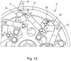
- FIG. 10 is a holding jaws 25 with the associated holding heads 26 moving rotary head 31 at least partially shown, which is synchronized with the packing head 5 is moved and a corresponding gear coupling 27 for movement of the holding jaws 25, so that a synchronized entrainment of the product P in conjunction with the holding stamp 15th is possible.
- the packing head 5 is additionally associated with a plurality of closure elements 28, 29, 30 and 31, which are partly fixed or rotatable or pivotable and fold the bottom of the package, while the product P is passed along with the packaging blank Z to this.
- the transfer of the product P together with the packaging blank Z to the packing head 5 takes place in the in Fig. 2
- the holding jaw pair 13 grips the gripper head 4, the product P and the associated packaging blank Z.
- the packing head 5 rotates further and the holding jaw 25 is retracted into the transport path of the product P (see Fig. 2 ), until the holding head 26 touches the underside of the product P.
- the product P and the packaging blank Z are held in this position between the holding punch 15 and the holding jaw 25 (see Fig. 3 ).
- the holding jaw pair 13 can be opened.
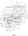
- the product P and the associated packaging blank Z are thus transferred from a lateral support by the holding jaw pair 13 to the holding punch 15 and the holding jaw 25 (see Fig. 4 ).
- the holding jaws 13.1 and 13.2 open so far that in the sequence the coupling gear halves 18.1 and 18.2 are actuated and the divisible, closed folding channel 14 along the axis of the holding punch 15 and along the product axis is moved radially outward.
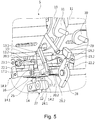
- This movement takes place substantially linearly and, as a rule, very quickly, so that the product P is moved onward by the packing head 5 only over a manageable pivoting range during this folding movement of the divisible folding channel 14.
- the folding channel 14 thus sweeps the packaging blank Z laterally against the product P, so that it bears tightly against the product P (see FIG Fig. 5 ).
- the folding channel 14 moves even further radially outward and at some distance below the product P, so that the packaging blank Z is continued to a kind of tube tail below the product P.
- the holding jaw pair 13 is closed again to hold the product P and the packaging blank Z again (see Fig. 6 ).
- the holding jaw 25 due to the gear coupling 27 performs a suitable tracking movement, so that the product P is securely pressed against the holding stamp 15.
- the ring halves 14.1 and 14.2 of the folding channel 14 can be opened by means of the coupling gear halves 18.1 and 18.2 and the opened folding channel 14 can be guided laterally on the product P and the holding jaw pair 13 back up.
- the product P and the packaging blank Z are then taken over again by the holding jaw pair 13 and conveyed on.
- the product P substantially retains its radial position relative to the axis of rotation of the packing head 5.
- the tracking of the holding jaw 25 and the holding stamp 15 as a stop.
- the holding jaws 13.1 and 13.2 then take the product P again substantially at the same position on the side region of the product P (see Fig. 7 ).
- the unfolded folding channel 14 is further radially inwardly in the direction of its in Fig. 2 shown starting position moves.
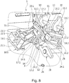
- the product P together with the packaging blank Z is then guided by means of the packing head 5 first to the closure element 28 and then to the other closure elements 29, 30, 31, so that then the bottom of the package is folded or closed (see Fig. 8 and 9 ).
- the folding channel 14 is then closed again by means of the coupling gear halves 18.1 and 18.2, ie the two ring halves 14.1 and 14 are moved together. This is mainly done by that the connecting coupling 22.1, 22.2 is pivoted, while the first pivot arm 20.1, 20.2 is substantially stationary.
- the opening of the folding channel 14 takes place by the connecting coupling 22.2 is pivoted counterclockwise.
- the linear movement of the Faltkanais 14 takes place by an active pivotal movement of the first pivot arm 20.1, 20.2, while the second pivot arm 21.1, 21.2 is carried at a stationary connection coupling 22.1, 22.2.
- the movement sequence described according to the invention can be carried out continuously and allows very high speeds, which is why the throughput of products P is very large.
- existing components of known packaging machines for example, the EMC packaging machine of Theeberg Pactec GmbH & Co. KG
- the changes mainly concern the packing head 5 and the rapier head 4 can be simplified. Only the additional action of the holding jaw 25 and the additional rotary head 32 are required.
Landscapes
- Engineering & Computer Science (AREA)
- Mechanical Engineering (AREA)
- Basic Packing Technique (AREA)
Abstract
Description
- Die vorliegende Erfindung betrifft einen Rotationskopf für eine Verpackungsmaschine insbesondere für kleinstückige Süßwarenprodukte, umfassend eine Mehrzahl von Haltebackenpaaren und eine Mehrzahl von teilbaren Faltkanälen (, die im Betrieb geöffnet und geschlossen werden), wobei jedem Haltebackenpaar ein teilbarer Faltkanal zugeordnet ist.
- Ein solcher Rotationskopf ist z.B. von der EMC-Verpackungsmaschine der Theegarten Pactec GmbH bekannt. Diese Maschine umfasst einen Greiferkopf, der einem Produkt jeweils einen Verpackungsmittelzuschnitt zuordnet und dann das Produkt zusammen mit dem Verpackungsmittelzuschnitt an einen Packkopf (Rotationskopf) übergibt. Der Packkopf weist einen teilbaren Bürstenring auf, der vor der Weitergabe des verpackten Produkts geöffnet und vor der Übergabe von dem Greiferkopf auf den Packkopf wieder geschlossen wird und durch den das Produkt zusammen mit dem Packmittelzuschnitt hindurchgedrückt wird. Hierzu weisen sowohl der Greiferkopf als auch der Packkopf Stößel auf, die das Produkt zusammen mit dem Packmittelzuschnitt zwischen der Oberseite und der Unterseite des Produkts Einklemmen und gemeinsam durch den Bürstenring hindurchbewegen. Hierdurch legt sich der Packmittelzuschnitt seitlich an das Produkt an. Während dieses Vorgangs sind sowohl die Haltebacken des Greiferkopfs als auch die Haltebacken des Packkopfes geöffnet. Das Haltebackenpaar des Packkopfes befindet sich dabei radial innenliegend zum Bürstenring. Im Anschluss an das Durchführen durch den Bürstenring wird dann am Packkopf noch die Endfaltung des Packmittelzuschnitts am Produkt durchgeführt. Der Übergabevorgang mittels der Stempel am Greiferkopf und am Packkopf erfordert lange Stempelwege und ist daher technisch aufwändig.
- Eine alternative Ausgestaltung eines Packkopfs mit Bürstenring ist in der
EP 0926071 A1 beschrieben. Hierbei handelt es sich aber um einen geschlossenen Bürstenring, der bestimmte Bewegungsabläufe am Packkopf nicht zulässt. Geschlossene Faltkanäle bzw. Faltringe sind auch aus derEP 1357026 A1 bekannt. Bei der letzteren Konstruktion ist der Faltkanal schwenkbar angeordnet. Aber auch hier sind gewisse Bewegungsabläufe nicht möglich, weil dieser Packkopf eine andere Übergabe des Produkts mit dem Packmittelzuschnitt erfordert. - Eine weitere alternative Konstruktion ist aus der
EP 2942294 B1 bekannt. Dort erfolgt das Durchführen durch einen Bürstenring nicht am Packkopf selbst, sondern innerhalb einer Einheit, die von dem Haltebackenpaar des Packkopfs durchfahren wird. Beschrieben ist lediglich ein schrittweises Bewegen des Packkopfs zum Hindurchführen des Produkts mit dem Packmittelzuschnitt durch den Bürstenring. Der Bürstenring ist teilbar und kann geöffnet und geschlossen werden, so dass er radial innenliegend zu den Halteabschnitten der Haltebacken zusammengefahren wird. Im Anschluss erfolgt dann eine Längsverschiebung des Bürs tenrings innerhalb der separaten Falteinheit. Zwar ist in dieser Druckschrift auch ein kontinuierliches Durchführen dieses Verfahrens angesprochen. Wie dies jedoch technisch umzusetzen ist, ergibt sich aus derEP 2942294 B1 nicht. Ein schrittweises Ausführen des mit dem Bürstenring durchgeführten Faltvorgangs bedingt einen geringeren Durchsatz. Es wird jedoch möglichst angestrebt, einen Durchsatz von mindestens 900 Produkten pro Minute zu erzielen. - Ein Bürstenring ist nur eine besondere Form eines Faltkanals. Generell können diese Faltkanäle auch durch bestimmte geometrische Innenkonturen einen genauen Anlegevorgang an das Produkt vorgeben. Ein Bürstenring führt ein Glattstreichen entlang der Seitenbereiche des Produkts durch.
- Es ist daher die Aufgabe der vorliegenden Erfindung, einen Rotationskopf für eine Verpackungsmaschine der eingangs genannten Art so zu verbessern, dass dieser in bestehende Maschinenkonzepte sehr leicht eingliederbar ist und mit hoher Geschwindigkeit betrieben werden kann.
- Hierzu ist erfindungsgemäß vorgesehen, dass der teilbare, sich im Betrieb von einer Öffnungs- in eine Schließstellung bewegende Faltkanal zum Ausüben einer Faltbewegung längsbeweglich am Rotationskopf angeordnet ist. Das Anordnen von Faltkanälen am Rotationskopf an sich ist zwar bekannt; jedoch nicht als teilbarer, d.h. sich im Betrieb öffnender und schließender, und längsbeweglicher Faltkanal, so dass z.B. ein Umsetzen des Faltkanals auch von einer radial außenliegenden Position zu einer radial innenliegenden Position um den Haltebereich der Haltebacken herum möglich ist. Hierbei können auch lineare oder nahezu lineare Bewegungen eingesetzt werden, die von der Rotationsrichtung des Rotationskopfes abweichen. Die Ausübung der Faltbewegung durch den teilbaren, sich von einer Öffnungs- in eine Schließstellung bewegbaren Faltkanal vereinfacht auch die Ausgestaltung der zugehörigen Haltemittel, die während dieses Vorgangs das Produkt zusammen mit dem Packmittelzuschnitt in Position halten. Dieser Vorgang kann entweder durch Haltemittel erfolgen, die gänzlich am Rotationskopf angeordnet sind, oder zumindest teilweise von außen auf diesen zugreifen. Bei der letzteren Variante ist jedoch die Kinematik für solche Haltemittelbestandteile vereinfacht, weil das Produkt zusammen mit dem Packmittelzuschnitt nicht aktiv durch den Faltkanal bewegt werden muss, sondern sich hauptsächlich der Faltkanal entlang des Produkts bewegt.
- Bei einer besonders vorteilhaften Ausführungsform der vorliegenden Erfindung kann der teilbare Faltkanal radial zur Rotationsachse des Rotationskopfs zum Ausüben der Faltbewegung längsbeweglich am Rotationskopf angeordnet sein. Bei dieser Ausgestaltung macht sich die Umsetzbarkeit der einzelnen Teile des Faltkanals besonders vorteilhaft bemerkbar, weil dieser von einer Seite zur anderen Seite des Haltebereichs des Haltebackenpaars bewegt werden kann, auch wenn das Haltebackenpaar zum Aufdrücken auf die Seitenbereiche des Produkts ausgestaltet ist.
- Günstigerweise kann der teilbare Faltkanal ein teilbarer Bürstenring sein. Hierbei handelt es sich um eine bevorzugte Ausgestaltung eines Faltkanals, der in vielen Fällen sehr schöne Verpackungsergebnisse erzielt und auch bei empfindlichen Produkten sehr gut einsetzbar ist.
- Günstigerweise kann der teilbare Faltkanal mittels eines Koppelgetriebes radial zur Rotationsachse zum Ausüben der Faltbewegung angetrieben sein, wobei das Koppelgetriebe Bestandteil des Rotationskopfes ist. Ein Koppelgetriebe stellt ein einfaches und effizientes sowie platzsparendes Mittel dar, die Bewegung des teilbaren Faltkanals auszuüben. Die Ansteuerung des Koppelgetriebes kann z.B. über Nocken und Kurvenbahnen erfolgen, so dass die entsprechende Bewegung auch bei einem schnell rotierenden Rotationskopf ausübbar ist.
- Bevorzugt kann das Koppelgetriebe den teilbaren Faltkanal sowohl zum Ausüben der Faltbewegung als auch zum Ausüben der Öffnungs- und Schließbewegung des Faltkanals antreibend ausgestaltet sein. Beide Bewegungsvorgänge werden demnach von ein und demselben Antrieb durchgeführt, wodurch sich eine Kosten- und Energieersparnis ergibt.
- Des Weiteren kann die Öffnungs- und Schließbewegung mittels zumindest radial verlagerbarer Schwenkachsen des Koppelgetriebes bewirkbar sein. Zusätzlich können die Schwenkachsen auch tangential verschoben werden. Naturgemäß muss nur ein Teil oder nur eine der Schwenkachsen des Koppelgetriebes diese Funktion ausführen, während in aller Regel die Basisschwenkachsen am Rotationskopf eine feste Position einnehmen.
- Gemäß einer weiteren Ausführungsform kann das Haltebackenpaar zum Halten der Seitenbereiche eines mit einem Packmittelzuschnitt teilweise umgebenen Produkts ausgebildet sein, wobei jedem Haltebackenpaar ein Haltestempel zugeordnet ist, der einen Anschlag für die radial innenliegende Seite des teilweise mit dem Packmittelzuschnitt umgebenen Produkts formt. Es besteht demnach nicht zwingend die Notwendigkeit, dass der Haltestempel am Rotationskopf längsbeweglich angeordnet ist. Dieser braucht lediglich als Anschlag zu wirken. Gegebenenfalls weist der Haltestempel eine Pufferfunktion auf, indem er z.B. federbeweglich ist, damit eine vorgegebene Haltekraft nicht überschritten wird. Dieser Haltestempel gibt dann auch die radiale Position des Produkts zusammen mit dem Packmittelzuschnitt am Rotationskopf vor.
- Darüber hinaus bezieht sich die Erfindung auf eine Vorrichtung mit einem Rotationskopf nach einem der Ansprüche 1 bis 6 und einer Haltebackeneinrichtung. Die Haltebackeneinrichtung kann mindestens eine Haltebacke aufweisen, die synchronisiert zur Rotation des Rotationskopfs in Richtung eines zugeordneten Haltestempels des Rotationskopfs derart bewegbar ist, dass über einen vorgegebenen Wegabschnitt die Haltebacke zusammen mit dem Haltestempel das teilweise mit dem Packmittelzuschnitt umgebene Produkt hält und das zugehörige Haltebackenpaar und der zugehörige Faltkanal derart angesteuert sind, dass das Haltebackenpaar während dieses Haltevorgangs durch die Haltebacke und den Haltestempel öffnet (d.h. den Weg für den Faltkanal freimacht) und der Faltkanal die Faltbewegung ausübt. Das Produkt zusammen mit dem Packmittelzuschnitt kann somit am Rotationskopf von dem Haltebackenpaar transportiert werden, über einen bestimmten Bereich losgelassen werden, damit die Faltbewegung des Faltkanals ausgeführt werden kann, und anschließend wieder von dem Haltebackenpaar für den Weitertransport ergriffen werden. Das Produkt mit dem Packmittelzuschnitt weist somit im Wesentlichen einen radial gleichen Abstand zur Rotationsachse des Rotationskopfes auf, während die Faltbewegung des Faltkanals ausgeübt wird. Dies ermöglicht auch radial kürzere Haltebacken, die weniger weit vorstehen, weil der Faltkanal sich am Rotationskopf selbst bewegt.
- Des Weiteren bezieht sich die Erfindung auf ein Verfahren zum Verpacken eines kleinteiligen Produktes, insbesondere Süßwarenproduktes, mit folgenden Schritten:
- Zuführen eines teilweise mit einem Packmittelzuschnitt versehenen Produkts an einen Rotationskopf,
- Anlegen des Packmittelzuschnitts zumindest an die Seitenbereiche des Produkts mittels eines sich mit dem Rotationskopf mit bewegenden, teilbaren Faltkanals, der zum Ausüben einer Faltbewegung längsbeweglich auf dem Rotationskopf angeordnet ist, und Zurückführen des Faltkanals im geteilten Zustand auf dem Rotationskopf. Ein solcher Bewegungsablauf eines Faltkanals an einem Rotationskopf war bislang nicht bekannt und eröffnet neue Möglichkeiten der Verpackung mit höheren Geschwindigkeiten, ohne bestehende Verfahrensabläufe zu sehr zu verändern.
- Das Verfahren kann weiter folgende Schritte umfassen:
- Ergreifen der Seitenbereiche des Produkts unter Zwischenfügung des Packmittelzuschnitts mittels einer ersten Halteeinrichtung,
- Übergeben des Produkts mit dem Packmittelzuschnitt an eine zweite Halteeinrichtung, die die radial innenliegende und die radial außenliegende Seite des teilweise mit dem Packmittelzuschnitt versehenen Produkts ergreift, wobei zumindest ein Haltemittel der zweiten Halteeinrichtung Bestandteil des Rotationskopfes ist, und
- Durchführen des Anlegeschritts mittels des teilbaren Faltkanals, während die zweite Halteeinrichtung das Produkt hält.
- Am Rotationskopf wirken somit zwei Halteeinrichtungen, die sich abwechseln. Der Anlegeschritt wird durchgeführt, während die zweite Halteeinrichtung das Produkt und den zugehörigen Packmittelzuschnitt hält und die erste Halteeinrichtung den Anlageschritt des teilbaren Faltkanals nicht stört.
- Günstigerweise kann das Verfahren weiter folgenden Schritt umfassen:
Zurückübergeben des Produkts mit dem Packmittelzuschnitt an die erste Halteeinrichtung. Die erste Halteeinrichtung übernimmt somit den generellen Transport des Produkts mit dem Packmittelzuschnitt durch den Rotationskopf, während lediglich für den Anlegeschritt eine Übergabe an die zweite Halteeinrichtung erfolgt. In der Folge können dann die weiteren Faltvorgänge durchgeführt werden. - Gemäß einer Verfahrensvariante kann als folgender Schritt vorgesehen sein: Öffnen des teilbaren Faltkanals nach dem Anlegeschritt. Durch das Öffnen des teilbaren Faltkanals kann der Weg freigegeben werden für die erste Halteeinrichtung, die das Produkt und den Packmittelzuschnitt ergreifen können. Dies vereinfacht die Bewegungsabläufe. Dieses ist jedoch nicht zwingend, weil ein Öffnen des teilbaren Faltkanals auch während oder nach dem Schließen der ersten Halteeinrichtung erfolgen kann.
- In der Folge kann dann als weiterer Schritt ausgeführt werden, dass der geöffnete Faltkanal zum Ausüben einer Rückführbewegung zur Startposition der Faltbewegung entgegen der Faltbewegungsrichtung am Rotationskopf bewegt wird, wenn das Produkt mit dem Packmittelzuschnitt an die erste Halteeinrichtung zurückübergeben wurde. Für diese Rückführbewegung steht ein relativ langer Rotationsweg des Rotationskopfes zur Verfügung, bis der Faltkanal seinen nächsten Anlegeschritt durchführen muss.
- In den meisten Fällen ist ein Anlegen des Packmittelzuschnitts an das Produkt über den gesamten seitlichen Umfang gewünscht, deshalb ist es von Vorteil, wenn das Verfahren weiter folgenden Schritt umfasst: Der Faltkanal wird vor dem Ausüben der Faltbewegung geschlossen.
- Von besonderem Vorteil ist es, wenn die erwähnten Schritte (in den Ansprüchen) sämtlich bei im Wesentlichen kontinuierlich rotierendem Rotationskopf durchgeführt werden. Hierdurch werden hohe Geschwindigkeiten erzielt. Darüber hinaus müssen Massen nicht zu stark beschleunigt und abgebremst werden, was auch produktschonender ist als ein schrittweises Arbeiten des Rotationskopfs.
- Im Folgenden wird ein Ausführungsbeispiel der vorliegenden Erfindung anhand einer Zeichnung näher erläutert. Es zeigen:
- Fig. 1
- eine schematische Darstellung einer Verpackungsvorrichtung, bei der der erfinddungsgemäße Rotationskopf zum Einsatz kommen kann,
- Fig. 2
- eine vereinfachte perspektivische Darstellung eines erfindungsgemäßen Rotationskopfes in einer ersten Stellung,
- Fig. 3
- eine vereinfachte perspektivische Darstellung eines erfindungsgemäßen Rotationskopfes in einer zweiten Stellung,
- Fig. 4
- eine vereinfachte perspektivische Darstellung eines erfindungsgemäßen Rotationskopfes in einer dritten Stellung,
- Fig. 5
- eine vereinfachte perspektivische Darstellung eines erfindungsgemäßen Rotationskopfes in einer vierten Stellung,
- Fig. 6
- eine vereinfachte perspektivische Darstellung eines erfindungsgemäßen Rotationskopfes in einer fünften Stellung,
- Fig. 7
- eine vereinfachte perspektivische Darstellung eines erfindungsgemäßen Rotationskopfes in einer sechsten Stellung,
- Fig. 8
- eine vereinfachte perspektivische Darstellung eines erfindungsgemäßen Rotationskopfes in einer siebten Stellung,
- Fig. 9
- eine vereinfachte perspektivische Darstellung eines erfindungsgemäßen Rotationskopfes in einer achten Stellung, und
- Fig. 10
- eine vereinfachte Vorderansicht eines Teils eines Rotationskopfes mit Haltebacken.
- Eine Verpackungsvorrichtung 1 für insbesondere kleinstückige Süßwarenprodukte ist schematisch in
Fig. 1 dargestellt. Die Verpackungsmaschine 1 umfasst im Wesentlichen einen Linearförderer 2 zum Zuführen der Produkte P, einen Aufnahmekopf 3 zum Aufnehmen der Produkte P und Weitergabe an einen Greiferkopf 4 zum Zuordnen eines Packmittelzuschnitts Z an das Produkt P, einen Packkopf 5 zum Ausüben der maßgeblichen Verpackungsschritte und einen Abgabekopf 6 zur Aufnahme und Abgabe der fertig verpackten Produkte P1 sowie eine Zuführeinheit 7 für Verpackungsmaterial. Im vorliegenden Fall umfasst die Zuführeinheit 7 für Verpackungsmaterial zwei Stationen für Packmittelrollen 8 und 9, wobei eine erste Packmittelrolle 8 abläuft und die zweite Packmittelrolle 9 vorbereitet und zugeschaltet wird, sobald die erste Packmittelrolle 8 leer ist. Der Aufnahmekopf 3, der Greiferkopf 4, der Packkopf 5 und der Abgabekopf 6 sind jeweils als Rotationsköpfe ausgeführt und mit entsprechenden Haltebackenpaaren zum Transport des Produkts P und gegebenenfalls des Packmittelzuschnitts Z versehen. Hierzu sind mehrere Haltebackenpaare gleichmäßig verteilt an den Umfängen der Rotationsköpfe angeordnet. Üblicherweise ordnet der Greiferkopf 4 einem Produkt P einen Packmittelzuschnitt Z zu, so dass der Packmittelzuschnitt Z L-förmig um das Produkt herumgeführt wird. Während der Übergabe an den Packkopf 5 wird der Packmittelzuschnitt Z in U-Form um das Produkt P gelegt. Die Haltebackenpaare des Greiferkopfs 4 und des Packkopfs 5 weisen hierzu in aller Regel eine um 90° zueinander verdrehte Öffnungs- und Schließrichtung auf, so dass ihre Haltebereiche zur Übergabe des Produkts P zusammen mit dem Packmittelzuschnitt Z ineinandergreifen können. - Die Erfindung befasst sich hauptsächlich mit der neuartigen Ausgestaltung des Packkopfes 5. Dessen Aufbau und Funktionsweise wird nunmehr anhand der
Figuren 2-9 näher erläutert. Zur Vereinfachung und Übersichtlichkeit ist nur eine Station des Packkopfes 5 mit den in der Folge näher erläuterten Einrichtungen versehen. Diese sind selbstverständlich bei jeder dieser Stationen 12 des Packkopfes 5 vorhanden. Zusätzlich ist zur besseren Übersichtlichkeit auch der Packmittelzuschnitt Z nicht dargestellt, sondern nur das Produkt P alleine. - Der Packkopf 5 ist als eine Art Rotationstrommel ausgeführt und dreht sich entgegen dem Uhrzeigersinn. In einer Aussparung 10 der Trommel 11 sind sternförmig verschiedene Stationen 12 des Packkopfs 5 angeordnet. Jede Station 12 verfügt über ein Haltebackenpaar 13, einen teilbaren Faltkanal 14 und einen Haltestempel 15. Der Haltestempel 15 bildet das Zentrum jeder Station 12, um das die übrigen Elemente angeordnet sind. Der Haltestempel 15 weist einen Anschlagkopf 16 auf, der die radiale Position des Produkts P zusammen mit dem Packmittelzuschnitt Z relativ zur Rotationsachse A des Packkopfes 5 vorgibt. Im vorliegenden Ausführungsbeispiel ist der Haltestempel 15 federbeweglich am Packkopf 5 angebracht.
- Das Haltebackenpaar 13 ist symmetrisch um den Haltestempel 15 angeordnet, so dass auf beiden Seiten des Haltestempels 15 jeweils eine Haltebacke 13.1 und 13.2 vorhanden ist. Die Haltebacken 13.1 und 13.2 sind in Rotationsrichtung des Packkopfes 5 hintereinander angeordnet, so dass die Haltebacke 13.1 in Drehrichtung vor dem Haltestempel 15 und die Haltebacke 13.2 hinter dem Haltestempel 15 positioniert ist. Die Haltenbacken 13.1 und 13.2 sind schwenkbar an der Trommel zum Ausführen einer Öffnungs- und Schließbewegung innerhalb der Aussparung 10 angeordnet.
- Der teilbare Faltkanal 14 (im vorliegenden Fall ein Bürstenring) weist jeweils die beiden Ringhälften 14.1 und 14.2 auf. Die Teilungsebene des teilbaren Faltkanals 14 liegt im Wesentlichen in der Schwenkebene des Haltebackenpaars 13. Jede Ringhälfte 14.1 und 14.2 des teilbaren Faltkanals 14 ist an einer Ringbasis 17.1 und 17.2 angebracht. Die Ringbasis 17.1 und 17.2 ist jeweils Bestandteil einer Koppelgetriebehälfte 18.1 und 18.2. Die Koppelgetriebehälften 18.1 und 18.2 sind jeweils seitlich neben der Aussparung 10 an der Trommel 11 angeordnet, so dass die Ringbasis 17.1 und 17.2 im Bereich der Aussparung 10 oder radial außerhalb der Aussparung 10 angeordnet ist. Jede Koppelgetriebehälfte 18.1 und 18.2 umfasst eine an der Trommel 11 angebrachte Getriebebasis 19.1, 19.2, an der ein erster Schwenkarm 20.1, 20.2 schwenkbar angeordnet ist. Der erste Schwenkarm 20.1, 20.2 ist mit dem radial weiter innenliegenden Teil der Ringbasis 17.1, 17.2 verbunden. Ein zweiter Schwenkarm 21.1, 21.2 ist mit dem radial weiter außenliegenden Teil der Ringbasis 17.1, näher an der Ringhälfte 14.1, 14.2 schwenkbar angebracht. Der zweite Schwenkarm 21.1, 21.2 ist schwenkbar an einer Verbindungskoppel 22.1, 22.2 angebracht. Die Verbindungskoppel 22.1, 22.2 ist mittels einer Schwenkwelle 23.1, 23.2 an der Getriebebasis 19.1, 19.2 angebracht. Die beiden Koppelgetriebehälften 18.1, 18.2 sind so ausgestaltet, dass der teilbare Faltkanal 14 längsbeweglich entlang des Haltestempels 15 angeordnet ist. Zusätzlich ermöglichen die Koppelgetriebehälften 18.1, 18.2 eine Öffnungs- und Schließbewegung der beiden Ringhälften 14.1, 14.2. Darüber hinaus sind die beiden Koppelgetriebehälften 18.2 so angesteuert, dass sie eine gleichzeitige Bewegung der Ringhälften 14.1, 14.2 bewirken. Die die Ringbasis 17.1 bzw. 17.2 mit den zugehörigen ersten und zweiten Schwenkarmen 20.1, 21.1 bzw. 20.1, 21.2 verbindenden Achsen bewegen sich radial und teilweise im Abstand entlang der Achse A des Packkopfes 5.
- Die Form der Haltebacken 13.1 und 13.2 ist so gewählt, dass ihr jeweiliger Haltebereich 24.2, der mit dem Produkt P und dem Packmittelzuschnitt Z zur Anlage kommt, so vorsteht, dass der Faltkanal 14, d.h. die beiden Ringhälften 14.1, 14.2 zwischen den Haltebacken 13.1, 13.2 angeordnet werden kann, wenn die beiden Haltebacken 13.1 und 13.2 das Produkt P halten (siehe
Fig. 2 ). - Dem Packkopf 5 ist eine von außen auf diesen einwirkende Haltebacke 25 zugeordnet. Die Haltebacke 25 bildet zusammen mit dem Haltestempel 15 eine Haltebackeneinrichtung, die in der Lage ist, das Produkt mit dem dazwischen gefügten Packmittelzuschnitt Z zumindest temporär festzuhalten, und zwar entlang einer Achse, die senkrecht zur Klemmachse des Haltebackenpaars 13 wirkt. Weil sich währen dieses Vorgangs der Packkopf 5 weiterdreht, muss die Haltebacke 25 eine Bewegung ausführen, die eine Zustellung eines Haltekopfs 26 an die Unterseite des Produkts P bewirkt und diesen so mitführt, dass der Haltekopf 26 dem von dem Packkopf 5 aufgeprägten Weg folgt. Hierzu ist die Haltebacke 25 mittels einer Getriebekoppel 27 entsprechend bewegbar ausgestaltet. Möglich ist auch die Anordnung der Haltebacke 25 auf einem Rotationskopf, so dass mehrere dieser Haltebacken 25 an diesem angeordnet sind und synchronisiert mit dem Produkt P in Kontakt treten. In
Fig. 10 ist ein die Haltebacken 25 mit den zugehörigen Halteköpfen 26 bewegender Rotationskopf 31 zumindest teilweise dargestellt, der synchronisiert zum Packkopf 5 bewegt wird und eine entsprechende Getriebekoppel 27 zur Bewegung der Haltebacken 25 aufweist, so dass eine synchronisierte Mitnahme des Produkts P im Zusammenspiel mit dem Haltestempel 15 möglich ist. - Dem Packkopf 5 sind zusätzlich noch mehrere Verschlusselemente 28, 29, 30 und 31 zugeordnet, die zum Teil feststehen oder drehbar bzw. schwenkbar angeordnet sind und den Boden der Verpackung fertigfalten, während das Produkt P zusammen mit dem Packmittelzuschnitt Z an diesen vorbeigeführt wird.
- Im Folgenden wird nunmehr anhand der
Fig. 2 bis 9 die Funktionsweise des Packkopfes 5 und der zugeordneten Haltebacke 25 näher erläutert. - Die Übergabe des Produktes P zusammen mit dem Packmittelzuschnitt Z an den Packkopf 5 erfolgt in der in
Fig. 2 dargestellten geschlossenen Stellung des teilbaren Faltkanals 14. Das Haltebackenpaar 13 ergreift vom Greiferkopf 4 das Produkt P und den zugehörigen Packmittelzuschnitt Z. Der Packkopf 5 dreht weiter und die Haltebacke 25 wird in den Transportweg des Produkts P eingefahren (sieheFig. 2 ), und zwar solange, bis der Haltekopf 26 die Unterseite des Produkts P berührt. Das Produkt P und der Packmittelzuschnitt Z sind in dieser Stellung zwischen dem Haltestempel 15 und der Haltebacke 25 gehalten (sieheFig. 3 ). In der Folge kann das Haltebackenpaar 13 geöffnet werden. Das Produkt P und der zugehörige Packmittelzuschnitt Z werden somit von einer seitlichen Halterung durch das Haltebackenpaar 13 an den Haltestempel 15 und die Haltebacke 25 übergeben (sieheFig. 4 ). Die Haltebacken 13.1 und 13.2 öffnen so weit, dass in der Folge die Koppelgetriebehälften 18.1 und 18.2 betätigt werden und der teilbare, geschlossene Faltkanal 14 entlang der Achse des Haltestempels 15 bzw. entlang der Produktachse radial nach außen bewegt wird. Diese Bewegung erfolgt im Wesentlichen linear und in aller Regel sehr schnell, damit das Produkt P bei dieser Faltbewegung des teilbaren Faltkanals 14 nur über einen überschaubaren Schwenkbereich vom Packkopf 5 weiterbewegt wird. Der Faltkanal 14 streicht somit den Packmittelzuschnitt Z seitlich an das Produkt P heran, so dass dieser eng an dem Produkt P anliegt (sieheFig. 5 ). - Anschließend fährt der Faltkanal 14 noch weiter radial nach außen und mit einigem Abstand unterhalb des Produkts P, so dass der Packmittelzuschnitt Z zu einer Art Schlauchschwanz unterhalb des Produkts P weiter fortgeführt ist. In dieser Stellung ist es möglich, dass das Haltebackenpaar 13 wieder zugefahren wird, um das Produkt P und den Packmittelzuschnitt Z wieder zu halten (siehe
Fig. 6 ). Während der ganzen Zeit vollführt die Haltebacke 25 aufgrund der Getriebekoppel 27 eine geeignete Nachführbewegung, so dass das Produkt P sicher an den Haltestempel 15 angedrückt ist. In der Folge kann nunmehr die Haltebacke 25 wieder zurückfahren, die Ringhälften 14.1 und 14.2 des Faltkanals 14 können mittels der Koppelgetriebehälften 18.1 und 18.2 geöffnet werden und der geöffnete Faltkanal 14 kann seitlich an dem Produkt P und dem Haltebackenpaar 13 wieder nach oben geführt werden. Das Produkt P und der Packmittelzuschnitt Z werden dann von dem Haltebackenpaar 13 wieder übernommen und weitergefördert. Bei dem gesamten Vorgang behält das Produkt P im Wesentlichen seine radiale Position, relativ zur Rotationsachse des Packkopfes 5 gesehen, bei. Hierfür sorgt die Nachführung der Haltebacke 25 und der Haltestempel 15 als Anschlag. Die Haltebacken 13.1 und 13.2 übernehmen das Produkt P dann wieder im Wesentlichen an derselben Position am Seitenbereich des Produkts P (sieheFig. 7 ). - Anschließend wird der auseinandergefahrene Faltkanal 14 weiter radial nach innen in Richtung seiner in
Fig. 2 dargestellten Ausgangsposition bewegt. Das Produkt P zusammen mit dem Packmittelzuschnitt Z wird dann mittels des Packkopfes 5 zunächst an dem Verschlusselement 28 und dann an dem weiteren Verschlusselementen 29, 30, 31 vorbeigeführt, so dass dann auch der Boden der Verpackung gefaltet bzw. geschlossen wird (sieheFig. 8 und9 ). Während der Packkopf 5 weiterdreht, wird dann mittels der Koppelgetriebehälften 18.1 und 18.2 der Faltkanal 14 wieder geschlossen, d.h. die beiden Ringhälften 14.1 und werden zusammengefahren. Dies geschieht hauptsächlich dadurch,
dass die Verbindungskoppel 22.1, 22.2 verschwenkt wird, während der erste Schwenkarm 20.1, 20.2 im Wesentlichen stillsteht. Das Öffnen des Faltkanals 14 erfolgt, indem die Verbindungskoppel 22.2 entgegen dem Uhrzeigersinn verschwenkt wird. Die Linearbewegung des Faltkanais 14 erfolgt durch eine aktive Schwenkbewegung des ersten Schwenkarms 20.1, 20.2, während der zweite Schwenkarm 21.1, 21.2 bei stillstehender Verbindungskoppel 22.1, 22.2 mitgeführt wird. - Der erfindungsgemäß beschriebene Bewegungsablauf kann kontinuierlich durchgeführt werden und erlaubt sehr hohe Geschwindigkeiten, weshalb der Durchsatz an Produkten P sehr groß ist. Darüber hinaus kann auf bestehende Bestandteile von bekannten Verpackungsmaschinen (z.B. EMC-Verpackungsmaschine der Theegarten Pactec GmbH & Co. KG) zurückgegriffen werden. Die Veränderungen betreffen hauptsächlich den Packkopf 5 und der Greiferkopf 4 kann vereinfacht werden. Lediglich die zusätzliche Einwirkung der Haltebacke 25 und der zusätzliche Rotationskopf 32 sind erforderlich.
- Im Gegensatz hierzu sind im Stand der Technik entweder lediglich schrittweise arbeitende Maschinen beschrieben oder die Bewegungsabläufe sind relativ komplex, die Faltkanäle ungeteilt oder es wird eine gänzlich andere Produktzuführung benötigt.
-
- 1
- Verpackungsmaschine
- 2
- Linearförder
- 3
- Aufnahmekopf
- 4
- Greiferkopf
- 5
- Packkopf
- 6
- Abgabekopf
- 7
- Zuführeinheit
- 8
- Packmittelrolle
- 9
- Packmittelrolle
- 10
- Aussparung
- 11
- Trommel
- 12
- Station
- 13
- Haltebackenpaar
- 14
- teilbarer Faltkanal
- 14.1,14.2
- Ringhälfte
- 15
- Haltestempel
- 16
- Anschlagkopf
- 17.1,17.2
- Ringbasis
- 18.1,18.2
- Koppelgetriebehälfte
- 19.1,19.2
- Getriebebasis
- 20.1,20.2
- erster Schwenkarm
- 21.1,21.2
- zweiter Schwenkarm
- 22.1,22.2
- Verbindungskoppel
- 23.1,23.2
- Schwenkwelle
- 24.1,24.2
- Haltebereich
- 25
- Haltebacke
- 26
- Haltekopf
- 27
- Getriebekoppel
- 28
- Verschlusselement
- 29
- Verschlusselement
- 30
- Verschlusselement
- 31
- Verschlusselement
- 32
- Rotationskopf
- A
- Rotationsachse
- P
- Produkt
- Z
- Packmittelzuschnitt
Claims (15)
- Rotationskopf (5) für eine Verpackungsmaschine (1), insbesondere für kleinstückige Süßwarenprodukte (P)1 umfassend eine Mehrzahl von Haltebackenpaaren (13) und eine Mehrzahl von teilbaren Faltkanälen (14), wobei jedem Haltebackenpaar (13) ein teilbarer Faltkanal (14) zugeordnet ist, dadurch gekennzeichnet, dass der teilbare, sich im Betrieb von einer Öffnungs- in eine Schließstellung bewegende Faltkanal (14) zum Ausüben einer Faltbewegung längsbeweglich am Rotationskopf (5) angeordnet ist.
- Rotationskopf (5) nach Anspruch 1, dadurch gekennzeichnet, dass der teilbare Faltkanal (14) radial zur Rotationsachse (A) des Rotationskopfs (5) zum Ausüben der Faltbewegung längsbeweglich am Rotationskopf (5) angeordnet ist.
- Rotationskopf (5) nach Anspruch 1 oder 2, dadurch gekennzeichnet, dass der teilbare Faltkanal (14) ein teilbarer Bürstenring ist.
- Rotationskopf (5) nach einem der Ansprüche 2 oder 3, dadurch gekennzeichnet, dass der teilbare Faltkanal (14) mittels eines Koppelgetriebes (18.1,18.2) radial zur Rotationsachse (A) zum Ausüben der Faltbewegung angetrieben ist und das Koppelgetriebe (18.1,18.2) Bestandteil des Rotationskopfes (5) ist.
- Rotationskopf (5) nach Anspruch 4, dadurch gekennzeichnet, dass das Koppelgetriebe radial zur Rotationsachse (A) zum Ausüben der Faltbewegung angetrieben ist und das Koppelgetriebe (18.1,18.2) den teilbaren Faltkanal (14) sowohl zum Ausüben der Faltbewegung als auch zum Ausüben der Öffnungs- und Schließbewegung des Faltkanals (14) antreibend ausgestaltet ist.
- Rotationskopf (5) nach Anspruch 5, dadurch gekennzeichnet, dass die Öffnungs-Schließbewegung mittels zumindest radial verlagerbarer Schwenkachsen des Koppelgetriebes (18.1,18.2) bewirkbar ist.
- Rotationskopf (5) nach einem der Ansprüche 1 bis 6, dadurch gekennzeichnet, dass das Haltebackenpaar (13) zum Halten der Seitenbereiche eines mit einem Packmittelzuschnitt (Z) teilweise umgebenen Produkts (P) ausgebildet ist, und dass jedem Haltebackenpaar (13) ein Haltestempel (15) zugeordnet ist, der einen Anschlag für die radial innenliegende Seite des teilweise mit dem Packmittelzuschnitt (Z) umgebenen Produkts (P) formt.
- Vorrichtung mit einem Rotationskopf (5) nach einem der Ansprüche 1 bis 7 und einer Haltebackeneinrichtung, dadurch gekennzeichnet, dass die Haltebackeneinrichtung mindestens eine Haltebacke (25) aufweist, die synchronisiert zur Rotation des Rotationskopfes (5) in Richtung eines zugeordneten Haltestempels (15) des Rotationskopfs (5) derart bewegbar ist, dass über einen vorgegebenen Wegabschnitt die Haltebacke (25) zusammen mit dem Haltestempel (15) das teilweise mit dem Produktmittelzuschnitt (Z) umgebene Produkt (P) hält und das zugehörige Haltebackenpaar (13) und er zugehörige Faltkanal (14) derart angesteuert sind, dass sich das Haltebackenpaar (13) währen dieses Haltevorgangs durch die Haltebacke (25) und den Haltestempel (15) öffnet und der Faltkanal (14) die Faltbewegung ausübt.
- Verfahren zum Verpacken eines kleinteiligen Produkts (P), insbesondere Süßwarenprodukts, mit folgenden Schritten:Zuführen eines teilweise mit einem Packmittelzuschnitt (Z) versehenen Produkts (P) an einen Rotationskopf (5),Anlegen des Packmittelzuschnitts (Z) zumindest an die Seitenbereiche des Produkts (P) mittels eines sich mit dem Rotationskopf (5) mit bewegenden, teilbaren Faltkanals (14), der zum Ausüben einer Faltbewegung längsbeweglich auf dem Rotationskopf (5) angeordnet ist, und Zurückführen des Faltkanals (14) im geteilten Zustand auf dem Rotationskopf (5).
- Verfahren nach Anspruch 9, das weiter folgende Schritte umfasst:Ergreifen der Seitenbereiche des Produkts (P) unter Zwischenfügung des Packmittelzuschnitts (Z) mittels einer ersten Halteeinrichtung,Übergeben des Produkts (P) mit dem Packmittelzuschnitt (Z) an eine zweite Halteeinrichtung, die die radial innenliegende und die radial außenliegende Seite des teilweise mit dem Packmittelzuschnitt (Z) versehenen Produkts (P) ergreift, wobei zumindest ein Haltemittel der zweiten Halteeinrichtung Bestandteil des Rotationskopfes (5) ist, undDurchführen des Anlegeschritts mittels des teilbaren Faltkanals (14), während die zweite Halteeinrichtung das Produkt (P) hält.Am Rotationskopf wirken somit zwei Halteeinrichtungen, die sich abwechseln. Der Anlegeschritt wird durchgeführt, während die zweite Halteeinrichtung das Produkt und den zugehörigen Packmittelzuschnitt hält.
- Verfahren nach Anspruch 10, das weiter folgenden Schritt umfasst:
Zurückübergeben des Produkts (P) mit dem Packmittelzuschnitt (Z) an die erste Halteeinrichtung. - Verfahren nach Anspruch 11, das weiter folgenden Schritt umfasst:
Öffnen des teilbaren Faltkanals (14) nach dem Anlageschritt. - Verfahren nach Anspruch 12, das weiter folgenden Schritt umfasst:
Bewegen des geöffneten Faltkanals (14) zum Ausüben einer Rückführbewegung zur Startposition der Faltbewegung entgegen der Faltbewegungsrichtung am Rotationskopf (5), wenn das Produkt (P) mit dem Packmittelzuschnitt (Z) an die erste Halteeinrichtung zurückübergeben wurde. - Verfahren nach Anspruch 13, das weiter folgenden Schritt umfasst:
Schließen des Faltkanals (14) vor dem Ausüben der Faltbewegung. - Verfahren nach einem der Ansprüche 9 bis 14, dadurch gekennzeichnet, dass die erwähnten Schritte sämtlich bei im Wesentlichen kontinuierlich rotierendem Rotationskopf (5) durchgeführt werden.
Applications Claiming Priority (1)
| Application Number | Priority Date | Filing Date | Title |
|---|---|---|---|
| DE102017127156.2A DE102017127156A1 (de) | 2017-11-17 | 2017-11-17 | Rotationskopf mit längsbeweglichem Faltkanal |
Publications (2)
| Publication Number | Publication Date |
|---|---|
| EP3486182A1 true EP3486182A1 (de) | 2019-05-22 |
| EP3486182B1 EP3486182B1 (de) | 2019-12-25 |
Family
ID=63174112
Family Applications (1)
| Application Number | Title | Priority Date | Filing Date |
|---|---|---|---|
| EP18188013.9A Active EP3486182B1 (de) | 2017-11-17 | 2018-08-08 | Rotationskopf mit längsbeweglichem faltkanal |
Country Status (3)
| Country | Link |
|---|---|
| EP (1) | EP3486182B1 (de) |
| DE (1) | DE102017127156A1 (de) |
| ES (1) | ES2776894T3 (de) |
Cited By (1)
| Publication number | Priority date | Publication date | Assignee | Title |
|---|---|---|---|---|
| DE202023101020U1 (de) | 2023-03-03 | 2023-03-17 | Theegarten-Pactec Gmbh & Co. Kg | Vorrichtung zum Verpacken eines Nahrungsmittelprodukts |
Citations (6)
| Publication number | Priority date | Publication date | Assignee | Title |
|---|---|---|---|---|
| CH173573A (de) * | 1933-11-01 | 1934-11-30 | Sapal Plieuses Automatiques | Einwickelmatrize für Einwickelmaschinen. |
| EP0733548A1 (de) * | 1995-03-22 | 1996-09-25 | NUOVA FIMA IMBALLAGGI S.r.l. | Vorrichtung zum Verpacken von verschiedenen Gegenständen, insbesondere von Süsswaren mit verschiedenen Formen |
| EP0926071A1 (de) | 1997-04-17 | 1999-06-30 | AZIONARIA COSTRUZIONI MACCHINE AUTOMATICHE-A.C.M.A.-S.p.A. | Einheit zum Glätten von umwickelten Schokoladeprodukten |
| EP1357026A1 (de) | 2002-04-22 | 2003-10-29 | THEEGARTEN-PACTEC GMBH & CO. KG | Vorrichtung und Verfahren zur Verpackung kleinstückiger Artikel |
| EP2942294B1 (de) | 2014-05-05 | 2016-11-02 | AZIONARIA COSTRUZIONI MACCHINE AUTOMATICHE-A.C.M.A.-S.p.A. | Umwicklungsverfahren und umwicklungsmaschine für süsswarenprodukte |
| WO2017017652A1 (en) * | 2015-07-29 | 2017-02-02 | Azionaria Costruzioni Macchine Automatiche A.C.M.A. S.P.A. | Machine for wrapping confectionery products |
-
2017
- 2017-11-17 DE DE102017127156.2A patent/DE102017127156A1/de not_active Withdrawn
-
2018
- 2018-08-08 ES ES18188013T patent/ES2776894T3/es active Active
- 2018-08-08 EP EP18188013.9A patent/EP3486182B1/de active Active
Patent Citations (6)
| Publication number | Priority date | Publication date | Assignee | Title |
|---|---|---|---|---|
| CH173573A (de) * | 1933-11-01 | 1934-11-30 | Sapal Plieuses Automatiques | Einwickelmatrize für Einwickelmaschinen. |
| EP0733548A1 (de) * | 1995-03-22 | 1996-09-25 | NUOVA FIMA IMBALLAGGI S.r.l. | Vorrichtung zum Verpacken von verschiedenen Gegenständen, insbesondere von Süsswaren mit verschiedenen Formen |
| EP0926071A1 (de) | 1997-04-17 | 1999-06-30 | AZIONARIA COSTRUZIONI MACCHINE AUTOMATICHE-A.C.M.A.-S.p.A. | Einheit zum Glätten von umwickelten Schokoladeprodukten |
| EP1357026A1 (de) | 2002-04-22 | 2003-10-29 | THEEGARTEN-PACTEC GMBH & CO. KG | Vorrichtung und Verfahren zur Verpackung kleinstückiger Artikel |
| EP2942294B1 (de) | 2014-05-05 | 2016-11-02 | AZIONARIA COSTRUZIONI MACCHINE AUTOMATICHE-A.C.M.A.-S.p.A. | Umwicklungsverfahren und umwicklungsmaschine für süsswarenprodukte |
| WO2017017652A1 (en) * | 2015-07-29 | 2017-02-02 | Azionaria Costruzioni Macchine Automatiche A.C.M.A. S.P.A. | Machine for wrapping confectionery products |
Cited By (1)
| Publication number | Priority date | Publication date | Assignee | Title |
|---|---|---|---|---|
| DE202023101020U1 (de) | 2023-03-03 | 2023-03-17 | Theegarten-Pactec Gmbh & Co. Kg | Vorrichtung zum Verpacken eines Nahrungsmittelprodukts |
Also Published As
| Publication number | Publication date |
|---|---|
| ES2776894T3 (es) | 2020-08-03 |
| EP3486182B1 (de) | 2019-12-25 |
| DE102017127156A1 (de) | 2019-05-23 |
Similar Documents
| Publication | Publication Date | Title |
|---|---|---|
| DE60303240T2 (de) | Verfahren und Vorrichtung zum Verpacken eines Produkts unter Verwendung einer flachen rohrförmigen Verpackung | |
| DE69500361T2 (de) | Verpackungsmaschine zum Entnehmen und Öffnen flach gefalteter Schachteln und zum Füllen dieser Schachteln mit entsprechenden Artikeln | |
| EP2706012B1 (de) | Schalenverschließmaschine | |
| DE69013222T2 (de) | Einwickelmaschine, insbesondere für Süssigkeiten und ähnliche Nahrungsmittel. | |
| DE102014102333A1 (de) | Vorrichtung und Verfahren zur Vorfaltung von Packungsmänteln | |
| DE69313940T2 (de) | Drehender Zuführmechanismus | |
| EP0909707B1 (de) | Vorrichtung zum Einschlagen von Gruppen von Zigarettenpackungen in Packmaterialzuschnitte | |
| DE19504594B4 (de) | Verpackungsstraße zur Erzeugung von Doppelpackungen | |
| DD233105A5 (de) | Vorrichtung zum einwickeln von bonbons oder aehnl. gegenstaenden | |
| EP3269539B1 (de) | Vorrichtung zum öffnen eines endbereichs eines schlauchförmigen sackkörpers | |
| DE69207045T2 (de) | Vorrichtung zum Überführen und Verpacken | |
| DE69606131T2 (de) | Kontinuierliches Verfahren zum Umhüllen von Gegenständen | |
| EP3486182B1 (de) | Rotationskopf mit längsbeweglichem faltkanal | |
| DE69728707T2 (de) | Verfahren und Vorrichtung zum Falten von Verpackungszuschnitten entlang vorgefalzten Linien | |
| DE3324984A1 (de) | Vorrichtung zum einwickeln von bonbons | |
| DE19920710B4 (de) | Vorrichtung zur Verpackung kleinstückiger Artikel | |
| DE60303530T2 (de) | Verfahren und Umhüllungsrad zum Verpacken von Produktstapeln | |
| DE3886191T2 (de) | Hilfsvorrichtung zum verschliessen der endklappen von tragförmigen kartons. | |
| DE2329534C3 (de) | Vorrichtung zum kontinuierlichen Einwickeln von Bonbons oder ähnlichen Kleinteilen | |
| DE1929666C3 (de) | Verpackungsvorrichtung für stabähnliche Gegenstände, insbesondere von Zigaretten | |
| DE60018008T2 (de) | Verfahren und vorrichtung zum kontinuierlichen umhüllen von gegenständen | |
| EP1270425B1 (de) | Verfahren und Vorrichtung zum Aufbringen von Etikettenhülsen auf Gegenstände | |
| EP1357026A1 (de) | Vorrichtung und Verfahren zur Verpackung kleinstückiger Artikel | |
| EP1712471B1 (de) | Vorrichtung und Verfahren zur Verpackung von Artikeln | |
| EP0753386A1 (de) | Vorrichtung zum Beschneiden von gefalteten Druckereierzeugnissen, wie Zeitungen, Zeitschriften, Broschüren und dergleichen |
Legal Events
| Date | Code | Title | Description |
|---|---|---|---|
| PUAI | Public reference made under article 153(3) epc to a published international application that has entered the european phase |
Free format text: ORIGINAL CODE: 0009012 |
|
| STAA | Information on the status of an ep patent application or granted ep patent |
Free format text: STATUS: REQUEST FOR EXAMINATION WAS MADE |
|
| 17P | Request for examination filed |
Effective date: 20190221 |
|
| AK | Designated contracting states |
Kind code of ref document: A1 Designated state(s): AL AT BE BG CH CY CZ DE DK EE ES FI FR GB GR HR HU IE IS IT LI LT LU LV MC MK MT NL NO PL PT RO RS SE SI SK SM TR |
|
| AX | Request for extension of the european patent |
Extension state: BA ME |
|
| GRAP | Despatch of communication of intention to grant a patent |
Free format text: ORIGINAL CODE: EPIDOSNIGR1 |
|
| STAA | Information on the status of an ep patent application or granted ep patent |
Free format text: STATUS: GRANT OF PATENT IS INTENDED |
|
| RIC1 | Information provided on ipc code assigned before grant |
Ipc: B65B 49/08 20060101ALN20190624BHEP Ipc: B65B 11/54 20060101ALI20190624BHEP Ipc: B65B 49/06 20060101AFI20190624BHEP Ipc: B65B 11/28 20060101ALI20190624BHEP Ipc: B65B 25/00 20060101ALI20190624BHEP |
|
| INTG | Intention to grant announced |
Effective date: 20190730 |
|
| GRAS | Grant fee paid |
Free format text: ORIGINAL CODE: EPIDOSNIGR3 |
|
| GRAA | (expected) grant |
Free format text: ORIGINAL CODE: 0009210 |
|
| STAA | Information on the status of an ep patent application or granted ep patent |
Free format text: STATUS: THE PATENT HAS BEEN GRANTED |
|
| AK | Designated contracting states |
Kind code of ref document: B1 Designated state(s): AL AT BE BG CH CY CZ DE DK EE ES FI FR GB GR HR HU IE IS IT LI LT LU LV MC MK MT NL NO PL PT RO RS SE SI SK SM TR |
|
| REG | Reference to a national code |
Ref country code: GB Ref legal event code: FG4D Free format text: NOT ENGLISH |
|
| REG | Reference to a national code |
Ref country code: CH Ref legal event code: NV Representative=s name: BOVARD AG PATENT- UND MARKENANWAELTE, CH Ref country code: CH Ref legal event code: EP |
|
| REG | Reference to a national code |
Ref country code: DE Ref legal event code: R096 Ref document number: 502018000556 Country of ref document: DE |
|
| REG | Reference to a national code |
Ref country code: AT Ref legal event code: REF Ref document number: 1216860 Country of ref document: AT Kind code of ref document: T Effective date: 20200115 |
|
| REG | Reference to a national code |
Ref country code: IE Ref legal event code: FG4D Free format text: LANGUAGE OF EP DOCUMENT: GERMAN |
|
| REG | Reference to a national code |
Ref country code: NL Ref legal event code: FP |
|
| PG25 | Lapsed in a contracting state [announced via postgrant information from national office to epo] |
Ref country code: GR Free format text: LAPSE BECAUSE OF FAILURE TO SUBMIT A TRANSLATION OF THE DESCRIPTION OR TO PAY THE FEE WITHIN THE PRESCRIBED TIME-LIMIT Effective date: 20200326 Ref country code: NO Free format text: LAPSE BECAUSE OF FAILURE TO SUBMIT A TRANSLATION OF THE DESCRIPTION OR TO PAY THE FEE WITHIN THE PRESCRIBED TIME-LIMIT Effective date: 20200325 Ref country code: LT Free format text: LAPSE BECAUSE OF FAILURE TO SUBMIT A TRANSLATION OF THE DESCRIPTION OR TO PAY THE FEE WITHIN THE PRESCRIBED TIME-LIMIT Effective date: 20191225 Ref country code: BG Free format text: LAPSE BECAUSE OF FAILURE TO SUBMIT A TRANSLATION OF THE DESCRIPTION OR TO PAY THE FEE WITHIN THE PRESCRIBED TIME-LIMIT Effective date: 20200325 Ref country code: FI Free format text: LAPSE BECAUSE OF FAILURE TO SUBMIT A TRANSLATION OF THE DESCRIPTION OR TO PAY THE FEE WITHIN THE PRESCRIBED TIME-LIMIT Effective date: 20191225 Ref country code: LV Free format text: LAPSE BECAUSE OF FAILURE TO SUBMIT A TRANSLATION OF THE DESCRIPTION OR TO PAY THE FEE WITHIN THE PRESCRIBED TIME-LIMIT Effective date: 20191225 Ref country code: SE Free format text: LAPSE BECAUSE OF FAILURE TO SUBMIT A TRANSLATION OF THE DESCRIPTION OR TO PAY THE FEE WITHIN THE PRESCRIBED TIME-LIMIT Effective date: 20191225 |
|
| REG | Reference to a national code |
Ref country code: LT Ref legal event code: MG4D |
|
| PG25 | Lapsed in a contracting state [announced via postgrant information from national office to epo] |
Ref country code: HR Free format text: LAPSE BECAUSE OF FAILURE TO SUBMIT A TRANSLATION OF THE DESCRIPTION OR TO PAY THE FEE WITHIN THE PRESCRIBED TIME-LIMIT Effective date: 20191225 Ref country code: RS Free format text: LAPSE BECAUSE OF FAILURE TO SUBMIT A TRANSLATION OF THE DESCRIPTION OR TO PAY THE FEE WITHIN THE PRESCRIBED TIME-LIMIT Effective date: 20191225 |
|
| PG25 | Lapsed in a contracting state [announced via postgrant information from national office to epo] |
Ref country code: AL Free format text: LAPSE BECAUSE OF FAILURE TO SUBMIT A TRANSLATION OF THE DESCRIPTION OR TO PAY THE FEE WITHIN THE PRESCRIBED TIME-LIMIT Effective date: 20191225 |
|
| PG25 | Lapsed in a contracting state [announced via postgrant information from national office to epo] |
Ref country code: EE Free format text: LAPSE BECAUSE OF FAILURE TO SUBMIT A TRANSLATION OF THE DESCRIPTION OR TO PAY THE FEE WITHIN THE PRESCRIBED TIME-LIMIT Effective date: 20191225 Ref country code: CZ Free format text: LAPSE BECAUSE OF FAILURE TO SUBMIT A TRANSLATION OF THE DESCRIPTION OR TO PAY THE FEE WITHIN THE PRESCRIBED TIME-LIMIT Effective date: 20191225 Ref country code: PT Free format text: LAPSE BECAUSE OF FAILURE TO SUBMIT A TRANSLATION OF THE DESCRIPTION OR TO PAY THE FEE WITHIN THE PRESCRIBED TIME-LIMIT Effective date: 20200520 Ref country code: RO Free format text: LAPSE BECAUSE OF FAILURE TO SUBMIT A TRANSLATION OF THE DESCRIPTION OR TO PAY THE FEE WITHIN THE PRESCRIBED TIME-LIMIT Effective date: 20191225 |
|
| REG | Reference to a national code |
Ref country code: ES Ref legal event code: FG2A Ref document number: 2776894 Country of ref document: ES Kind code of ref document: T3 Effective date: 20200803 |
|
| PG25 | Lapsed in a contracting state [announced via postgrant information from national office to epo] |
Ref country code: IS Free format text: LAPSE BECAUSE OF FAILURE TO SUBMIT A TRANSLATION OF THE DESCRIPTION OR TO PAY THE FEE WITHIN THE PRESCRIBED TIME-LIMIT Effective date: 20200425 Ref country code: SM Free format text: LAPSE BECAUSE OF FAILURE TO SUBMIT A TRANSLATION OF THE DESCRIPTION OR TO PAY THE FEE WITHIN THE PRESCRIBED TIME-LIMIT Effective date: 20191225 Ref country code: SK Free format text: LAPSE BECAUSE OF FAILURE TO SUBMIT A TRANSLATION OF THE DESCRIPTION OR TO PAY THE FEE WITHIN THE PRESCRIBED TIME-LIMIT Effective date: 20191225 |
|
| REG | Reference to a national code |
Ref country code: DE Ref legal event code: R097 Ref document number: 502018000556 Country of ref document: DE |
|
| PG25 | Lapsed in a contracting state [announced via postgrant information from national office to epo] |
Ref country code: DK Free format text: LAPSE BECAUSE OF FAILURE TO SUBMIT A TRANSLATION OF THE DESCRIPTION OR TO PAY THE FEE WITHIN THE PRESCRIBED TIME-LIMIT Effective date: 20191225 |
|
| PLBE | No opposition filed within time limit |
Free format text: ORIGINAL CODE: 0009261 |
|
| STAA | Information on the status of an ep patent application or granted ep patent |
Free format text: STATUS: NO OPPOSITION FILED WITHIN TIME LIMIT |
|
| 26N | No opposition filed |
Effective date: 20200928 |
|
| PG25 | Lapsed in a contracting state [announced via postgrant information from national office to epo] |
Ref country code: PL Free format text: LAPSE BECAUSE OF FAILURE TO SUBMIT A TRANSLATION OF THE DESCRIPTION OR TO PAY THE FEE WITHIN THE PRESCRIBED TIME-LIMIT Effective date: 20191225 |
|
| PG25 | Lapsed in a contracting state [announced via postgrant information from national office to epo] |
Ref country code: MC Free format text: LAPSE BECAUSE OF FAILURE TO SUBMIT A TRANSLATION OF THE DESCRIPTION OR TO PAY THE FEE WITHIN THE PRESCRIBED TIME-LIMIT Effective date: 20191225 |
|
| PG25 | Lapsed in a contracting state [announced via postgrant information from national office to epo] |
Ref country code: LU Free format text: LAPSE BECAUSE OF NON-PAYMENT OF DUE FEES Effective date: 20200808 |
|
| REG | Reference to a national code |
Ref country code: BE Ref legal event code: MM Effective date: 20200831 |
|
| PG25 | Lapsed in a contracting state [announced via postgrant information from national office to epo] |
Ref country code: BE Free format text: LAPSE BECAUSE OF NON-PAYMENT OF DUE FEES Effective date: 20200831 Ref country code: IE Free format text: LAPSE BECAUSE OF NON-PAYMENT OF DUE FEES Effective date: 20200808 |
|
| PG25 | Lapsed in a contracting state [announced via postgrant information from national office to epo] |
Ref country code: TR Free format text: LAPSE BECAUSE OF FAILURE TO SUBMIT A TRANSLATION OF THE DESCRIPTION OR TO PAY THE FEE WITHIN THE PRESCRIBED TIME-LIMIT Effective date: 20191225 Ref country code: MT Free format text: LAPSE BECAUSE OF FAILURE TO SUBMIT A TRANSLATION OF THE DESCRIPTION OR TO PAY THE FEE WITHIN THE PRESCRIBED TIME-LIMIT Effective date: 20191225 Ref country code: CY Free format text: LAPSE BECAUSE OF FAILURE TO SUBMIT A TRANSLATION OF THE DESCRIPTION OR TO PAY THE FEE WITHIN THE PRESCRIBED TIME-LIMIT Effective date: 20191225 |
|
| PG25 | Lapsed in a contracting state [announced via postgrant information from national office to epo] |
Ref country code: MK Free format text: LAPSE BECAUSE OF FAILURE TO SUBMIT A TRANSLATION OF THE DESCRIPTION OR TO PAY THE FEE WITHIN THE PRESCRIBED TIME-LIMIT Effective date: 20191225 |
|
| PG25 | Lapsed in a contracting state [announced via postgrant information from national office to epo] |
Ref country code: SI Free format text: LAPSE BECAUSE OF FAILURE TO SUBMIT A TRANSLATION OF THE DESCRIPTION OR TO PAY THE FEE WITHIN THE PRESCRIBED TIME-LIMIT Effective date: 20191225 |
|
| REG | Reference to a national code |
Ref country code: AT Ref legal event code: MM01 Ref document number: 1216860 Country of ref document: AT Kind code of ref document: T Effective date: 20230808 |
|
| PG25 | Lapsed in a contracting state [announced via postgrant information from national office to epo] |
Ref country code: AT Free format text: LAPSE BECAUSE OF NON-PAYMENT OF DUE FEES Effective date: 20230808 |
|
| PG25 | Lapsed in a contracting state [announced via postgrant information from national office to epo] |
Ref country code: AT Free format text: LAPSE BECAUSE OF NON-PAYMENT OF DUE FEES Effective date: 20230808 |
|
| PGFP | Annual fee paid to national office [announced via postgrant information from national office to epo] |
Ref country code: NL Payment date: 20250826 Year of fee payment: 8 |
|
| PGFP | Annual fee paid to national office [announced via postgrant information from national office to epo] |
Ref country code: ES Payment date: 20250902 Year of fee payment: 8 |
|
| PGFP | Annual fee paid to national office [announced via postgrant information from national office to epo] |
Ref country code: DE Payment date: 20250828 Year of fee payment: 8 |
|
| PGFP | Annual fee paid to national office [announced via postgrant information from national office to epo] |
Ref country code: IT Payment date: 20250827 Year of fee payment: 8 |
|
| PGFP | Annual fee paid to national office [announced via postgrant information from national office to epo] |
Ref country code: GB Payment date: 20250827 Year of fee payment: 8 |
|
| PGFP | Annual fee paid to national office [announced via postgrant information from national office to epo] |
Ref country code: FR Payment date: 20250826 Year of fee payment: 8 |
|
| PGFP | Annual fee paid to national office [announced via postgrant information from national office to epo] |
Ref country code: CH Payment date: 20250901 Year of fee payment: 8 |
|
| PGFP | Annual fee paid to national office [announced via postgrant information from national office to epo] |
Ref country code: AT Payment date: 20260410 Year of fee payment: 5 |