EP3486341A1 - Aluminiumlegierung und elektrisch leitendes element, batterieelement, befestigungselement, federelement und strukturbauteil damit - Google Patents
Aluminiumlegierung und elektrisch leitendes element, batterieelement, befestigungselement, federelement und strukturbauteil damit Download PDFInfo
- Publication number
- EP3486341A1 EP3486341A1 EP17827609.3A EP17827609A EP3486341A1 EP 3486341 A1 EP3486341 A1 EP 3486341A1 EP 17827609 A EP17827609 A EP 17827609A EP 3486341 A1 EP3486341 A1 EP 3486341A1
- Authority
- EP
- European Patent Office
- Prior art keywords
- aluminum alloy
- alloy material
- mass
- working
- wire
- Prior art date
- Legal status (The legal status is an assumption and is not a legal conclusion. Google has not performed a legal analysis and makes no representation as to the accuracy of the status listed.)
- Granted
Links
Images


Classifications
-
- C—CHEMISTRY; METALLURGY
- C22—METALLURGY; FERROUS OR NON-FERROUS ALLOYS; TREATMENT OF ALLOYS OR NON-FERROUS METALS
- C22C—ALLOYS
- C22C21/00—Alloys based on aluminium
- C22C21/12—Alloys based on aluminium with copper as the next major constituent
- C22C21/16—Alloys based on aluminium with copper as the next major constituent with magnesium
-
- C—CHEMISTRY; METALLURGY
- C21—METALLURGY OF IRON
- C21D—MODIFYING THE PHYSICAL STRUCTURE OF FERROUS METALS; GENERAL DEVICES FOR HEAT TREATMENT OF FERROUS OR NON-FERROUS METALS OR ALLOYS; MAKING METAL MALLEABLE, e.g. BY DECARBURISATION OR TEMPERING
- C21D8/00—Modifying the physical properties of ferrous metals or ferrous alloys by deformation combined with, or followed by, heat treatment
- C21D8/06—Modifying the physical properties of ferrous metals or ferrous alloys by deformation combined with, or followed by, heat treatment during manufacturing of rods or wires
-
- C—CHEMISTRY; METALLURGY
- C22—METALLURGY; FERROUS OR NON-FERROUS ALLOYS; TREATMENT OF ALLOYS OR NON-FERROUS METALS
- C22C—ALLOYS
- C22C21/00—Alloys based on aluminium
-
- C—CHEMISTRY; METALLURGY
- C22—METALLURGY; FERROUS OR NON-FERROUS ALLOYS; TREATMENT OF ALLOYS OR NON-FERROUS METALS
- C22C—ALLOYS
- C22C21/00—Alloys based on aluminium
- C22C21/02—Alloys based on aluminium with silicon as the next major constituent
-
- C—CHEMISTRY; METALLURGY
- C22—METALLURGY; FERROUS OR NON-FERROUS ALLOYS; TREATMENT OF ALLOYS OR NON-FERROUS METALS
- C22C—ALLOYS
- C22C21/00—Alloys based on aluminium
- C22C21/06—Alloys based on aluminium with magnesium as the next major constituent
-
- C—CHEMISTRY; METALLURGY
- C22—METALLURGY; FERROUS OR NON-FERROUS ALLOYS; TREATMENT OF ALLOYS OR NON-FERROUS METALS
- C22C—ALLOYS
- C22C21/00—Alloys based on aluminium
- C22C21/06—Alloys based on aluminium with magnesium as the next major constituent
- C22C21/08—Alloys based on aluminium with magnesium as the next major constituent with silicon
-
- C—CHEMISTRY; METALLURGY
- C22—METALLURGY; FERROUS OR NON-FERROUS ALLOYS; TREATMENT OF ALLOYS OR NON-FERROUS METALS
- C22C—ALLOYS
- C22C21/00—Alloys based on aluminium
- C22C21/12—Alloys based on aluminium with copper as the next major constituent
- C22C21/14—Alloys based on aluminium with copper as the next major constituent with silicon
-
- C—CHEMISTRY; METALLURGY
- C22—METALLURGY; FERROUS OR NON-FERROUS ALLOYS; TREATMENT OF ALLOYS OR NON-FERROUS METALS
- C22F—CHANGING THE PHYSICAL STRUCTURE OF NON-FERROUS METALS AND NON-FERROUS ALLOYS
- C22F1/00—Changing the physical structure of non-ferrous metals or alloys by heat treatment or by hot or cold working
- C22F1/04—Changing the physical structure of non-ferrous metals or alloys by heat treatment or by hot or cold working of aluminium or alloys based thereon
- C22F1/043—Changing the physical structure of non-ferrous metals or alloys by heat treatment or by hot or cold working of aluminium or alloys based thereon of alloys with silicon as the next major constituent
-
- C—CHEMISTRY; METALLURGY
- C22—METALLURGY; FERROUS OR NON-FERROUS ALLOYS; TREATMENT OF ALLOYS OR NON-FERROUS METALS
- C22F—CHANGING THE PHYSICAL STRUCTURE OF NON-FERROUS METALS AND NON-FERROUS ALLOYS
- C22F1/00—Changing the physical structure of non-ferrous metals or alloys by heat treatment or by hot or cold working
- C22F1/04—Changing the physical structure of non-ferrous metals or alloys by heat treatment or by hot or cold working of aluminium or alloys based thereon
- C22F1/047—Changing the physical structure of non-ferrous metals or alloys by heat treatment or by hot or cold working of aluminium or alloys based thereon of alloys with magnesium as the next major constituent
-
- C—CHEMISTRY; METALLURGY
- C22—METALLURGY; FERROUS OR NON-FERROUS ALLOYS; TREATMENT OF ALLOYS OR NON-FERROUS METALS
- C22F—CHANGING THE PHYSICAL STRUCTURE OF NON-FERROUS METALS AND NON-FERROUS ALLOYS
- C22F1/00—Changing the physical structure of non-ferrous metals or alloys by heat treatment or by hot or cold working
- C22F1/04—Changing the physical structure of non-ferrous metals or alloys by heat treatment or by hot or cold working of aluminium or alloys based thereon
- C22F1/05—Changing the physical structure of non-ferrous metals or alloys by heat treatment or by hot or cold working of aluminium or alloys based thereon of alloys of the Al-Si-Mg type, i.e. containing silicon and magnesium in approximately equal proportions
-
- C—CHEMISTRY; METALLURGY
- C22—METALLURGY; FERROUS OR NON-FERROUS ALLOYS; TREATMENT OF ALLOYS OR NON-FERROUS METALS
- C22F—CHANGING THE PHYSICAL STRUCTURE OF NON-FERROUS METALS AND NON-FERROUS ALLOYS
- C22F1/00—Changing the physical structure of non-ferrous metals or alloys by heat treatment or by hot or cold working
- C22F1/04—Changing the physical structure of non-ferrous metals or alloys by heat treatment or by hot or cold working of aluminium or alloys based thereon
- C22F1/057—Changing the physical structure of non-ferrous metals or alloys by heat treatment or by hot or cold working of aluminium or alloys based thereon of alloys with copper as the next major constituent
-
- H—ELECTRICITY
- H01—ELECTRIC ELEMENTS
- H01B—CABLES; CONDUCTORS; INSULATORS; SELECTION OF MATERIALS FOR THEIR CONDUCTIVE, INSULATING OR DIELECTRIC PROPERTIES
- H01B1/00—Conductors or conductive bodies characterised by the conductive materials; Selection of materials as conductors
- H01B1/02—Conductors or conductive bodies characterised by the conductive materials; Selection of materials as conductors mainly consisting of metals or alloys
- H01B1/023—Alloys based on aluminium
-
- C—CHEMISTRY; METALLURGY
- C22—METALLURGY; FERROUS OR NON-FERROUS ALLOYS; TREATMENT OF ALLOYS OR NON-FERROUS METALS
- C22C—ALLOYS
- C22C2200/00—Crystalline structure
-
- C—CHEMISTRY; METALLURGY
- C22—METALLURGY; FERROUS OR NON-FERROUS ALLOYS; TREATMENT OF ALLOYS OR NON-FERROUS METALS
- C22F—CHANGING THE PHYSICAL STRUCTURE OF NON-FERROUS METALS AND NON-FERROUS ALLOYS
- C22F1/00—Changing the physical structure of non-ferrous metals or alloys by heat treatment or by hot or cold working
-
- Y—GENERAL TAGGING OF NEW TECHNOLOGICAL DEVELOPMENTS; GENERAL TAGGING OF CROSS-SECTIONAL TECHNOLOGIES SPANNING OVER SEVERAL SECTIONS OF THE IPC; TECHNICAL SUBJECTS COVERED BY FORMER USPC CROSS-REFERENCE ART COLLECTIONS [XRACs] AND DIGESTS
- Y02—TECHNOLOGIES OR APPLICATIONS FOR MITIGATION OR ADAPTATION AGAINST CLIMATE CHANGE
- Y02E—REDUCTION OF GREENHOUSE GAS [GHG] EMISSIONS, RELATED TO ENERGY GENERATION, TRANSMISSION OR DISTRIBUTION
- Y02E60/00—Enabling technologies; Technologies with a potential or indirect contribution to GHG emissions mitigation
- Y02E60/10—Energy storage using batteries
Definitions
- the present invention relates to an aluminum alloy material having a high strength.
- Such an aluminum alloy material is used for a wide range of applications (for example, a conductive member, a battery member, a fastening component, a spring component, and a structural component).
- An iron-based or copper-based wire rod has been widely used as the metal fine wire. These days, there is considered substitution of the iron-based or copper-based metal material to an aluminum-based material having a small specific gravity, a large thermal expansion coefficient, comparatively good electrical and heat conductivities, and excellent corrosion resistance, particularly having a small elastic coefficient, and flexibly elastically deformed as compared with the iron-based or copper-based metal material.
- a pure aluminum material has the following problem: it has a lower strength than that of the iron-based or copper-based metal material.
- a 2000 or 7000-series aluminum alloy material which is an aluminum-based alloy material having a comparatively high strength has the following problem: it has poor corrosion resistance and stress corrosion cracking resistance.
- a 6000-series aluminum alloy material which contains Mg and Si and has excellent electrical and heat conductivities, and excellent corrosion resistance.
- Such a 6000-series aluminum alloy material has a higher strength in aluminum-based alloy materials, but it does not have a sufficient strength, whereby a further improvement in a strength is desired.
- Patent Literature 1 a method according to crystallization of an aluminum alloy material containing an amorphous phase
- Patent Literature 2 a method for forming fine crystal grains according to the ECAP method
- Patent Literature 3 a method for forming fine crystal grains according to cold working at a temperature equal to or less than room temperature
- Patent Literature 4 a method for dispersing carbon nanofibers
- the methods manufacture aluminum alloy materials having small sizes, which make it difficult to industrially put the aluminum alloy materials to practical use.
- Patent Literature 5 A method for controlling a rolling temperature to obtain an Al-Mg-based alloy having a fine structure is disclosed in Patent Literature 5.
- the method has excellent industrial mass productivity, but a further improvement in a strength is required.
- an aluminum alloy material has a predetermined alloy composition, wherein: the aluminum alloy material has a fibriform metallographic structure where crystal grains extend so as to be aligned in one direction; and in a cross section parallel to the one direction, an average value of a size perpendicular to a longitudinal direction of the crystal grains is 270 nm or less, whereby the aluminum alloy material is obtained, which has excellent heat resistance and a high strength comparable to that of an iron-based or copper-based metal material.
- the present invention has been completed based on the above knowledge.
- the present invention can provide an aluminum alloy material having a predetermined alloy composition, wherein the aluminum alloy material has a fibriform metallographic structure where crystal grains extend so as to be aligned in one direction; and in a cross section parallel to the one direction, an average value of a size perpendicular to a longitudinal direction of the crystal grains is 270 nm or less, whereby the aluminum alloy material has excellent heat resistance and a high strength comparable to that of an iron-based or copper-based metal material. Furthermore, the present invention can provide a conductive member, a battery member, a fastening component, a spring component, and a structural component including the aluminum alloy material.
- the aluminum alloy material according to the present invention has an alloy composition consisting of 0.2 to 1.8% by mass of Mg, 0.2 to 2.0% by mass of Si, 0.01 to 1.50% by mass of Fe, 0.06 to 2% by mass in total of at least one selected from Cu, Ag, Zn, Ni, Co, Au, Mn, Cr, V, Zr, and Sn, with the balance containing Al and inevitable impurities, wherein: the aluminum alloy material has a fibriform metallographic structure where crystal grains extend so as to be aligned in one direction; and in a cross section parallel to the one direction, the average value of a size perpendicular to the longitudinal direction of the crystal grains is 270 nm or less.
- crystal grains refer to portions surrounded by orientation difference boundaries.
- orientation difference boundary refers to a boundary where contrast discontinuously changes in a case in which a metallographic structure is observed by scanning transmission electron microscopy (STEM). The size perpendicular to the longitudinal direction of the crystal grains corresponds to the interval of the orientation difference boundaries.
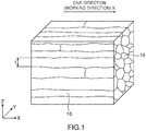
- the aluminum alloy material according to the present invention has a fibriform metallographic structure where crystal grains extend so as to be aligned in one direction.
- Fig. 1 shows a perspective view schematically showing the situation of the metallographic structure of the aluminum alloy material according to the present invention.
- the aluminum alloy material of the present invention has a fibriform structure where crystal grains 10 each having an elongated shape extend so as to be aligned in one direction X.
- the crystal grains each having an elongated shape are completely different from conventional fine crystal grains and flat crystal grains each merely having a large aspect ratio.
- the crystal grains of the present invention each have an elongated shape as with a fiber, and the average value of a size t perpendicular to a longitudinal direction X thereof is 270 nm or less.
- the fibriform metallographic structure where the fine crystal grains extend so as to be aligned in one direction can be said to be a novel metallographic structure which is not included in a conventional aluminum alloy.
- the aluminum alloy material of the present invention has the fibriform metallographic structure where the crystal grains extend so as to be aligned in one direction, and in the cross section parallel to the one direction, the average value of the size perpendicular to the longitudinal direction of the crystal grains is controlled to 270 nm or less, whereby a high strength (for example, a tensile strength of 480 MPa or more and a Vickers hardness (HV) of 125 or more) comparable to that of an iron-based or copper-based metal material can be attained.
- a high strength for example, a tensile strength of 480 MPa or more and a Vickers hardness (HV) of 125 or more
- the fine crystal grain size leads directly to an effect of improving grain boundary corrosion, an effect of improving fatigue characteristics, an effect of reducing the roughness of a surface after plastic working, and an effect of reducing sagging and burr during shearing working, or the like in addition to an improvement in a strength, which provides effects of generally improving the functions of the material.
- Mg manganesium
- Mg-Si cluster as a solute atom cluster
- the above function effects are insufficient.
- the Mg content is 0.2 to 1.8% by mass, and preferably 0.4 to 1.0% by mass.
- Si has an effect of strengthening by forming a solid solution in an aluminum matrix, and has an effect of improving a tensile strength and bending fatigue resistance by a synergistic effect with Mg.
- Mg-Si cluster or an Si-Si cluster as a solute atom cluster it is an element having an effect of improving a tensile strength and an elongation.
- an Si content is less than 0.2% by mass, the above function effects are insufficient.
- the Si content is 0.2 to 2.0% by mass, and preferably 0.4 to 1.0% by mass.
- Fe is an element which contributes to refinement of crystal grains by forming an Al-Fe based intermetallic compound and provides an improved tensile strength.
- the intermetallic compound refers to a compound composed of two or more kinds of metals. Fe dissolves in Al only by 0.05% by mass at 655°C, and even less at room temperature. Accordingly, the remaining Fe which cannot dissolve in Al is crystallized or precipitated as an intermetallic compound such as Al-Fe, Al-Fe-Si, or Al-Fe-Si-Mg.
- An intermetallic compound mainly composed of Fe and Al as exemplified by the above-described intermetallic compounds is herein referred to as an Fe-based compound.
- This intermetallic compound contributes to the refinement of crystal grains and provides an improved tensile strength.
- Fe has, also by Fe which has dissolved in Al, an effect of providing an improved tensile strength.
- an Fe content is less than 0.01% by mass, these function effects are insufficient.
- the Fe content is in excess of 1.50% by mass, a crystallized material increases, which causes deterioration in workability.
- the crystallized material refers to an intermetallic compound occurring during the casting solidification of an alloy. Therefore, the Fe content is 0.01 to 1.50% by mass, and preferably 0.05 to 0.80% by mass.
- the Fe content is more preferably less than 1.00% by mass, and still more preferably less than 0.60% by mass.
- Each of Cu (copper), Ag (silver), Zn (zinc), Ni (nickel), Co (cobalt), Au (gold), Mn (manganese), Cr (chromium), V (vanadium), Zr (zirconium), and Sn (stannum) is an element which provides improved heat resistance. Only any one type of these components may be contained singly, or the components may be contained in combination of two or more types.
- Examples of a mechanism in which the components provide improved heat resistance include a mechanism which reduces the energy of a crystal grain boundary since the difference between the atomic radius of each of the components and the atomic radius of aluminum is large, a mechanism which reduces the mobility of the grain boundary in a case in which each of the components enters into the grain boundary since the diffusion coefficient of the component is large, and a mechanism which delays a diffusion phenomenon since the interaction of the components with holes is large to trap the holes. These mechanisms are considered to act synergistically.
- any one or more selected from Zn, Ni, Co, Mn, Cr, V, Zr, and Sn is preferably contained. Furthermore, in a case in which the total of the contents of the components is less than 0.06% by mass, the function effect is insufficient. In a case in which the contents of the contents of the components are in excess of 2% by mass, workability decreases. Therefore, the total of the contents of at least one or more selected from Cu, Ag, Zn, Ni, Co, Au, Mn, Cr, V, Zr, and Sn is 0.06 to 2% by mass, and preferably 0.3 to 1.2% by mass.
- the balance i.e., components other than those described above, includes Al (aluminum) and inevitable impurities.
- the inevitable impurities mean impurities contained by an amount which may be contained inevitably during a manufacturing process. Since the inevitable impurities may cause a decrease in conductivity depending on the content thereof, it is preferable to suppress the content of the inevitable impurities to some extent considering the decrease in the conductivity.
- components which are inevitable impurities include B (boron), Ti (titanium), Bi (bismuth), Pb (lead), Ga (gallium), and Sr (strontium).
- the upper limit of the content of each of the components may be 0.05% by mass or less, and the total amount of the components may be 0.15% by mass or less.
- Such an aluminum alloy material can be obtained by combining and controlling alloy compositions and manufacturing processes.
- a suitable manufacturing method of the aluminum alloy material of the present invention is described.
- Such an aluminum alloy material according to one example of the present invention particularly attains an improvement in a strength by introducing a crystal grain boundary into an Al-Mg-Si-Fe-based alloy at a high density. Therefore, an approach to an improvement in a strength is largely different from that in a method for precipitation-hardening a Mg-Si compound which has been generally performed in a conventional aluminum alloy material.
- an aluminum alloy material having a predetermined alloy composition is subjected to cold working [1] at a degree of working of 4 or more as last working without subjecting the aluminum alloy material to an aging precipitation heat treatment [0].
- Refine annealing [2] may be performed after the cold working [1] if needed.
- crystal slip occurs as the elementary step of the deformation of a metal crystal.
- the metal material in which the crystal slip is apt to occur has small stress required for deformation, whereby it can be said to be have a low strength. Therefore, it is important to suppress the crystal slip which occurs in the metallographic structure in order to provide the improvement in the strength of the metal material.
- Examples of the prevention factor of such crystal slip include the existence of the crystal grain boundary in the metallographic structure. Such a crystal grain boundary can prevent the crystal slip from spreading in the metallographic structure in a case in which the deformation stress is applied to the metal material. As a result, the strength of the metal material is improved.
- the crystal grain boundary is desirably introduced at a high density into the metallographic structure.
- the formation mechanism of the crystal grain boundary is considered to be the division of the metal crystal involving the following deformation of the metallographic structure, for example.
- the formed crystal grain boundary has surface energy in a structure deviated from the closest packed atomic arrangement of usual twelve coordination. Therefore, it is considered that, in the usual metallographic structure, in a case in which the crystal grain boundary has a given density or more, the increased internal energy serves as a driving force, whereby dynamic or static recovery and recrystallization occur. Therefore, usually, it is considered that the increase and reduction of the crystal grain boundary simultaneously occur even if the amount of deformation is increased, whereby a grain boundary density is saturated.
- Fig. 2 shows a graph of the relationship between the degree of working and tensile strength of each of pure aluminum, pure copper, and the aluminum alloy material according to the present invention.
- pure aluminum or pure copper which is a usual metallographic structure has an improved tensile strength (hardening) at a comparatively low degree of working, but as the degree of working increases, the amount of hardening tends to be saturated.
- the degree of working corresponds to the amount of deformation applied to the metallographic structure
- the saturation of the amount of hardening corresponds to the saturation of the grain boundary density.
- the aluminum alloy material of the present invention is continuously hardened even if the degree of working increases, and the strength of the aluminum alloy material continuously increases with working.
- the aluminum alloy material of the present invention has the above alloy composition, and particularly, predetermined amounts of Mg and Si are compositely added to the aluminum alloy material, whereby the increase in the internal energy can be suppressed even if the crystal grain boundary has a given density or more in the metallographic structure. This is considered to make it possible to prevent recovery and recrystallization in the metallographic structure, and effectively increase the crystal grain boundary in the metallographic structure.
- the mechanism of the improvement in the strength provided by the composite addition of Mg and Si is not necessarily clear.
- the mechanism is considered to be based on the following (i) and (ii): (i) by combining and using a Mg atom having a greater atomic radius than that of an Al atom and an Si atom having a smaller atomic radius than that of the Al atom, the atoms are always filled densely (arranged) in the aluminum alloy material; and (ii) by causing divalent Mg and tetravalent Si to coexist with respect to a trivalent Al atom, a trivalent state can be formed in the entire aluminum alloy material, which attains valence stability, whereby the increase in the internal energy involving working can be effectively suppressed.
- the degree of working in the cold working [1] is set to 4 or more.
- working at a large degree of working makes it possible to prompt the division of the metal crystal involving the deformation of the metallographic structure, and to introduce the crystal grain boundary into the aluminum alloy material at a high density.
- the grain boundary of the aluminum alloy material is strengthened to largely improve the strength.
- Such a degree of working is set to preferably 5 or more, more preferably 6 or more, and still more preferably 7 or more.
- the upper limit of the degree of working is not particularly prescribed, and usually 15 or less.
- a degree of working ⁇ is represented by the following formula (1) in a case in which a cross-sectional area before working is taken as s1, and a cross-sectional area after working is taken as s2 (s1>s2).
- a working rate is preferably set to 98.2% or more, and more preferably 99.8% or more.
- a working rate R is represented by the following formula (2) using the above s1 and s2.
- a working method may be appropriately selected according to the intended shape (a wire bar, a plate, a strip, a foil or the like) of the aluminum alloy material, and examples thereof include a cassette roller die, groove roll rolling, round wire rolling, drawing working using a die or the like, and swaging.
- Various conditions kind of lubricating oil, working speed, and working heat generation or the like) in the above working may be appropriately adjusted in a known range.
- the aluminum alloy material is not particularly limited as long as it has the above alloy composition.
- the aging precipitation heat treatment [0] which has been conventionally performed before the cold working [1] is not performed.
- Such an aging precipitation heat treatment [0] usually retains the aluminum alloy material at 160 to 240°C for 1 minute to 20 hours, to prompt precipitation of a Mg-Si compound.
- the above cold working [1] at the high degree of working cannot be performed since working cracks occur in the material. Since a high aging temperature causes an overaging state, the working cracks may not occur even in the above cold working [1] at the high degree of working.
- Mg and Si are discharged from an Al matrix phase as a Mg-Si compound, whereby the stability of the grain boundary remarkably deteriorates.
- the refine annealing [2] may be performed after the cold working [1] for the purposes of release of residual stress and an improvement in an elongation.
- a treatment temperature is set to 50 to 160°C.
- the treatment temperature of the refine annealing [2] is less than 50°C, the above effects are less likely obtained.
- the treatment temperature is in excess of 160°C, recovery or recrystallization causes the growth of the crystal grains to occur, which causes a decrease in the strength.
- the retention time of the refine annealing [2] is preferably 1 to 48 hours.
- the various conditions of such a heat treatment can be appropriately adjusted according to the kind and amount of inevitable impurities, and the solid solution/precipitation state of the aluminum alloy material.
- the aluminum alloy material is subjected to working at a high degree of working according to a method such as drawing using a die, or rolling. Therefore, as a result, an elongated aluminum alloy material is obtained.
- a conventional method for manufacturing an aluminum alloy material such as powder sintering, compression torsion working, high pressure torsion (HPT), forge working, or equal channel angular pressing (ECAP) makes it difficult to provide the elongated aluminum alloy material.
- the aluminum alloy material of the present invention is preferably manufactured so as to have a length of 10 m or more.
- the upper limit of the length of the aluminum alloy material during manufacturing is not particularly provided, and preferably 6000 m or less in consideration of workability or the like.
- the configuration of the present invention is likely to be attained as the diameter of the aluminum alloy material of the present invention is smaller, particularly, in a case in which the aluminum alloy material is produced as a wire bar, or as the thickness of the aluminum alloy material is smaller in a case in which the aluminum alloy material is produced as a plate or a foil.
- the wire bar has a wire diameter of preferably 1 mm or less, more preferably 0.5 mm or less, still more preferably 0.1 mm or less, and particularly preferably 0.07 mm or less.
- the upper limit is not particularly provided, and preferably 30 mm or less.
- the aluminum alloy wire bar of the present invention has one advantage that it can be used as a thin single wire.
- the aluminum alloy material of the present invention is slimly or thinly worked.
- a plurality of aluminum alloy materials are prepared and joined to provide a large or thick product, which can also be used for the intended application.
- a known method can be used for the joining method, and examples thereof include pressure welding, welding, joining using an adhesive, and friction stirring joining.
- the aluminum alloy material is the wire bar
- a plurality of wire bars are bundled, and twisted to provide a twisted product, which can also be used for the intended application as an aluminum alloy twisted wire.
- the aluminum alloy material subjected to the cold working [1] may be subjected to working according to joining or twisting, and then subjected to the step of the refine annealing [2].
- the aluminum alloy material of the present invention manufactured by the above manufacturing method is obtained by introducing the crystal grain boundary at a high density into the metallographic structure.
- the aluminum alloy material of the present invention is characterized by having the fibriform metallographic structure where the crystal grains extend so as to be aligned in one direction, and in the cross section parallel to the one direction, the average value of a size perpendicular to the longitudinal direction of the crystal grains is 270 nm or less.
- the aluminum alloy material has a non-conventional specific metallographic structure, whereby the aluminum alloy material can exhibit a particularly excellent strength.
- the metallographic structure of the aluminum alloy material of the present invention is the fibriform structure, and the crystal grains each having an elongated shape extend in fiber forms so as to be aligned in one direction.
- the "one direction" corresponds to the working direction of the aluminum alloy material.
- the aluminum alloy material is the wire bar
- the "one direction” corresponds to a wire drawing direction, for example.
- the aluminum alloy material is a plate or a foil
- the "one direction” corresponds to a rolling direction, for example.
- the aluminum alloy material of the present invention exhibits a particularly excellent strength with respect to tensile stress parallel to the working direction.
- the one direction preferably corresponds to the longitudinal direction of the aluminum alloy material.
- the working direction of the aluminum alloy material usually corresponds to the longitudinal direction.
- the average value of a size perpendicular to the longitudinal direction of the crystal grains is 270 nm or less, more preferably 220 nm or less, still more preferably 170 nm or less, and particularly preferably 120 nm or less.
- the crystal grain boundary is formed at a high density.
- the lower limit of the average value of a size perpendicular to the longitudinal direction of the crystal grains is preferably 50 nm or more from the viewpoint of preventing deterioration in ductility.
- the size of the longitudinal direction of the crystal grains is not necessarily specified, and preferably 1200 nm or more, more preferably 1700 nm or more, and still more preferably 2200 nm or more.
- the aspect ratio of the crystal grains is preferably in excess of 10, and more preferably 20 or more.
- the upper limit of the aspect ratio of the crystal grains is preferably 2 million or less from the viewpoint of preventing deterioration in ductility.
- a tensile strength is measured according to JIS Z2241: 2011. Detailed measurement conditions are described in the column of Examples to be described below.
- the aluminum alloy material of the present invention has a tensile strength of preferably 480 MPa or more. This is a strength equivalent to that of a copper wire subjected to wire drawing working at a general high degree of working.
- the aluminum alloy material has a tensile strength of more preferably 520 MPa or more, still more preferably 560 MPa or more, particularly preferably 600 MPa or more, and yet still more preferably 640 MPa or more.
- the aluminum alloy material of the present invention having such a high strength can be used as substitution of a strong wire drawing worked material made of a thin copper alloy such as a Cu-Sn and Cu-Cr alloy.
- Such an aluminum alloy material can also be used as substitution of a steel-based or stainless-based material.
- the upper limit of the tensile strength of the aluminum alloy material of the present invention is not particularly limited, and 1000 MPa or less, for example. Since the aluminum alloy material of the present invention has excellent heat resistance, the aluminum alloy material can maintain the above high tensile strength even after heating.
- a Vickers hardness (HV) is a value measured according to JIS Z 2244: 2009. Detailed measurement conditions are described in the column of Examples to be described below.
- the Vickers hardness (HV) of a worked product which has been already turned into a component can be measured as follows: the worked product is disassembled; the cross section thereof is subjected to mirror polishing; and the Vickers hardness of the cross section is measured.
- the Vickers hardness (HV) is preferably 125 or more. This is a strength equivalent to that of a copper wire subjected to general strong wire drawing working.
- the Vickers hardness (HV) of the aluminum alloy material is more preferably 140 or more, still more preferably 150 or more, particularly preferably 160 or more, and yet still more preferably 170 or more.
- the aluminum alloy material of the present invention having such a high strength can be used as substitution of a strong wire drawing worked material made of a thin copper alloy such as a Cu-Sn or Cu-Cr alloy. Such an aluminum alloy material can also be used as substitution of a steel-based or stainless-based material.
- the upper limit of the Vickers hardness (HV) of the aluminum alloy material of the present invention is not particularly limited, and 300 or less, for example, and preferably 250 or less.
- the aluminum alloy material of the present invention can be directed to all the applications in which an iron-based material, a copper-based material, and an aluminum-based material are used.
- the aluminum alloy material can be suitably used as a conductive member such as an electric wire or a cable, a battery member such as a current collector mesh or net, a fastening component such as a screw, a bolt, or a rivet, a spring component such as a coil spring, an electric contact spring member such as a connector or a terminal, a structural component such as a shaft or a frame, a guide wire, a semiconductor bonding wire, and a winding wire used for a dynamo or a motor, or the like. Since the aluminum alloy material of the present invention has also excellent heat resistance, the aluminum alloy material is more suitable for the application particularly requiring heat resistance.
- the conductive member include a power electric wire such as an overhead power line, OPGW, a subterranean electric wire, or a submarine cable, a communication electric wire such as a telephone cable or a coaxial cable, an appliance electric wire such as a wired drone cable, a cab tire cable, an EV/HEV charge cable, a twisted cable for wind power on the ocean, an elevator cable, an umbilical cable, a robot cable, a train overhead wire, or a trolley wire, a transportation electric wire such as an automobile wire harness, a vessel electric wire, and an airplane electric wire, a bus bar, a lead frame, a flexible flat cable, a lightning rod, an antenna, a connector, a terminal, and a cable braid.
- a power electric wire such as an overhead power line, OPGW, a subterranean electric wire, or a submarine cable
- a communication electric wire such as a telephone cable or a coaxial cable
- an appliance electric wire such as a wired drone cable, a
- Examples of the battery member include a solar cell electrode.
- the structural member include a scaffold in a construction site, a conveyor mesh belt, a clothing metal fiber, a chain armor, a fence, an insect repellent net, a zipper, a fastener, a clip, aluminum wool, a bicycle component such as a brake or a spoke, a reinforcement wire made of tempered glass, a pipe seal, a metal packing, a protection reinforcing material for a cable, a fan belt cored bar, for driving an actuator, a chain, a hanger, a sound isolation mesh, and a shelf board.
- fastening member examples include a set screw, a staple, and a drawing pin.
- the spring member include a spring electrode, a terminal, a connector, a semiconductor probe spring, a blade spring, and a flat spiral spring.
- the aluminum alloy material is suitable also as a metal fiber to be added in order to apply conductivity to a resin-based material, a plastic material, and a cloth or the like, and to control the strength and elastic modulus thereof.
- the aluminum alloy material is suitable also as a consumer member and a medical member such as an eyeglass frame, a clock belt, a nib of a fountain pen, a fork, a helmet, or an injection needle.
- the aluminum alloy having a high strength of the present invention is particularly suitably used as a metal conductor constituting a health care wearable device requiring high elasticity.
- a high material strength not easily causing plastic deformation, and good fatigue characteristics causing no fracture even under repeated deformation are required for the metal conductor.
- an aluminum alloy is preferably used as compared with a metal which is apt to cause allergy such as copper. Copper reacts with sweat or the like emitted from the human body, which disadvantageously causes occurrence of discoloration or rust.
- the aluminum alloy is advantageously less likely to cause such a problem.
- Comparative Example 1 an aluminum wire rod (diameter: 0.24 mm) was produced under a manufacturing condition shown in Table 1 using a bar made of 99.99% by mass of Al and having a diameter of 10 mm.
- Manufacturing conditions A to K shown in Table 1 are specifically as follows.
- the prepared bar was subjected to cold working [1] at a degree of working of 5.5.
- the bar was not subjected to refine annealing [2].
- the bar was subjected to cold working [1] under the same condition as the manufacturing condition A except that the degree of working of the cold working [1] was set to 6.5.
- the bar was subjected to cold working [1] under the same condition as the manufacturing condition A except that the degree of working of the cold working [1] was set to 7.5.
- the bar was subjected to cold working [1] under the same condition as the manufacturing condition A except that the degree of working of the cold working [1] was set to 10.0.
- the prepared bar was subjected to cold working [1] at a degree of working of 4.5, and then subjected to refine annealing [2] at a treatment temperature of 60°C for a retention time of 1 hour.
- the bar was subjected to cold working [1] and refine annealing [2] under the same condition as the manufacturing condition E except that the degree of working of the cold working [1] was set to 5.5.
- the bar was subjected to cold working [1] and refine annealing [2] under the same condition as the manufacturing condition E except that the degree of working of the cold working [1] was set to 6.5.
- the bar was subjected to cold working [1] and refine annealing [2] under the same condition as the manufacturing condition E except that the degree of working of the cold working [1] was set to 10.0.
- the bar was subjected to cold working [1] under the same condition as the manufacturing condition A except that the degree of working of the cold working [1] was set to 3.5.
- the prepared bar was subjected to an aging precipitation heat treatment [0] at a treatment temperature of 180°C for a retention time of 10 hours, and then subjected to cold working [1]. However, since breaking of wire occurred frequently, the work was stopped.
- the prepared bar was subjected to cold working [1]. However, since breaking of wire occurred frequently, the work was stopped.
- An Al bare metal for electricity was dissolved.
- Mg simple substance, an Al-25% by mass Si master alloy, an Al-6% by mass Fe alloy, an Al-50% by mass Cu master alloy, and an Al-10% by mass Cr master alloy were added thereto, and dissolved, to manufacture a molten metal having an alloy composition of Al-1.03Mg-0.90Si-0.20Fe-0.16Cu-0.15Cr.
- the molten metal was continuously cast and rolled by a belt-and-wheel type continuous casting rolling machine, to obtain a drawing stock having a diameter of 9.5 mm.
- the obtained drawing stock was subjected to solution water hardening at 520°C, an artificial aging treatment in which it was retained at 200°C for 4 hours, wire drawing working at a working rate of 86.4% (degree of working: 2.0), and tempering at 140°C for 4 hours, to obtain an aluminum alloy wire rod (diameter: 3.5 mm).
- a drawing stock (diameter: 18 mm) was obtained by belt-and-wheel type continuous casting rolling. The obtained drawing stock was subjected to first wire drawing working at a working rate of 47% (degree of working: 0.63), to set the diameter thereof to 9.5 mm, a solution treatment at 520°C for 2 hours, and thereafter water hardening.
- the drawing stock was subjected to an aging treatment at 200°C for 4 hours, second wire drawing working at a working rate of 86% (degree of working: 2.0), and a heat treatment at 140°C for 4 hours, to obtain an aluminum alloy wire rod (diameter: 3.5 mm).
- the bar was subjected to first wire drawing working at a degree of working of 2.6, a primary heat treatment at 300 to 450°C for 0.5 to 4 hours, second wire drawing working at a degree of working of 3.6, a secondary heat treatment at 555°C for 0.15 seconds in a continuous current heat treatment, and thereafter an aging heat treatment at 175°C for 15 hours, to obtain an aluminum alloy wire rod (diameter: 0.43 mm).
- a cumulative equivalent strain of 4.0 was introduced by the ECAP method.
- a recrystallization temperature obtained at this stage was 300°C.
- the wire was subjected to prior heating in an inactive gas atmosphere at 250°C for 2 hours.
- the wire was subjected to a first wire drawing treatment at a working rate of 29% (degree of working: 0.34).
- a recrystallization temperature obtained at this stage was 300°C.
- the wire was subjected to a primary heat treatment in an inactive gas atmosphere at 260°C for 2 hours.
- the wire was passed at a drawing speed of 500 mm/min in a water-cooled wire drawing die, to be subjected to a second wire drawing treatment at a degree of working of 9.3.
- a recrystallization temperature obtained at this stage was 280°C.
- the wire was subjected to a secondary heat treatment in an inactive gas atmosphere at 220°C for 1 hour, to obtain an aluminum alloy wire rod (diameter: 0.08 mm).
- the aluminum alloy wire rods according to the Examples and the Comparative Examples were subjected to evaluation of characteristics to be shown below.
- the evaluation conditions of the characteristics are as follows. The results are shown in Table 1.
- Measurement was performed by the emission spectrochemical analysis method according to JIS H1305: 2005. The measurement was performed using an emission spectrophotometer (manufactured by Hitachi High-Tech Science Corporation).
- a metallographic structure was observed by scanning transmission electron microscopy (STEM) using a transmission electron microscope JEM-3100FEF (manufactured by JEOL Co., Ltd.).
- An observation sample to be used was cut at a cross section parallel to the longitudinal direction (wire drawing direction X) of the wire rod by focused ion beam (FIB) so as to have a thickness of 100 nm ⁇ 20 nm, and finished by ion milling.
- FIB focused ion beam
- the observed field of view was set to (15 to 40) ⁇ m ⁇ (15 to 40) ⁇ m, and a center and a position near the middle of a surface layer (center side position separated by about 1/4 of a wire diameter from the surface layer side) on a line corresponding to a wire diameter direction (direction perpendicular to a longitudinal direction) in the cross section were observed.
- the observed field of view was appropriately adjusted according to the size of a crystal grain.
- Fig. 3 shows a part of the STEM image of the cross section parallel to the longitudinal direction (wire drawing direction X) of the wire rod of Example 14 photographed during the STEM observation.
- the fibriform metallographic structure was estimated as "presence" in a case in which the metallographic structure as shown in Fig. 3 was observed.
- each observed field of view optional 100 crystal grains were selected.
- the size perpendicular to the longitudinal direction of each crystal grain and the size parallel to the longitudinal direction of the crystal grain were measured, to calculate the aspect ratio of the crystal grain.
- the average values of the size perpendicular to the longitudinal direction of the crystal grains and the aspect ratios were calculated from the total of the observed crystal grains. In a case in which the observed crystal grains were clearly larger than 400 nm, the number of selection of the crystal grains whose size was measured was reduced, and the average value thereof was calculated. In a case in which the size parallel to the longitudinal direction of the crystal grains was clearly 10 or more times the size perpendicular to the longitudinal direction of the crystal grains, the crystal grains were determined to uniformly have an aspect ratio of 10 or more.
- the wire rods before heating, having a tensile strength of 480 MPa or more were considered to be at a pass level.
- the wire rods after heating, having a tensile strength of 480 MPa or more were defined as "very good”.
- the wire rods after heating, having a tensile strength of less than 480 MPa and 420 MPa or more were defined as "good”.
- the wire rods after heating, having a tensile strength of less than 420 MPa were defined as "poor”.
- the Vickers hardness (HV) was preferably greater, and the Vickers hardness of 125 or more was considered to be at a pass level in the present Examples.
- the aluminum alloy wire rod according to each of Examples 1 to 17 of the present invention has a specific alloy composition, and the aluminum alloy wire rod has a fibriform metallographic structure where crystal grains extend so as to be aligned in one direction; and in a cross section parallel to the one direction, a size perpendicular to a longitudinal direction of the crystal grains is 270 nm or less.
- Fig. 3 shows the STEM image of the cross section parallel to the wire drawing direction of the aluminum alloy wire rod according to Example 14. The same metallographic structure as that of Fig. 3 was confirmed also in the cross section parallel to the longitudinal direction of the aluminum alloy wire rod according to each of Examples 1 to 13 and 15 to 17.
- the aluminum metal wire rod according to each of Examples 1 to 17 of the present invention having such a specific metallographic structure exhibits a high strength comparable to that of an iron-based or copper-based metal material (for example, tensile strength: 480 MPa or more, Vickers hardness (HV): 125 or more). Since the aluminum metal wire rod according to each of Examples 1 to 15 of the present invention contains at least one or more selected from Cu, Ag, Zn, Ni, Co, Au, Mn, Cr, V, Zr, and Sn in predetermined amounts, the aluminum metal wire rod was confirmed to have a high tensile strength maintained even after heating and excellent heat resistance.
- tensile strength 480 MPa or more
- HV Vickers hardness
- the aluminum metal wire rod of Comparative Example 4 not containing Cu, Ag, Zn, Ni, Co, Au, Mn, Cr, V, Zr, and Sn was confirmed to have a tensile strength largely decreased after heating, and poorer heat resistance than that of the aluminum alloy wire rod of each of Examples 1 to 17 according to the present invention.
- the alloy composition of the aluminum alloy wire rod of each of Comparative Examples 1 to 3 and 9 to 13 does not satisfy the appropriate range of the present invention, or does not have a fibriform metallographic structure where crystal grains extend so as to be aligned in one direction; and a size perpendicular to a longitudinal direction of the crystal grains is also 500 nm or more. It was confirmed that the aluminum alloy wire rod of each of Comparative Examples 1 to 3 and 9 to 13 has a remarkably poorer tensile strength and Vickers hardness (HV) than those of the aluminum alloy wire rod of each of Examples 1 to 15 according to the present invention.
- HV Vickers hardness
Landscapes
- Chemical & Material Sciences (AREA)
- Engineering & Computer Science (AREA)
- Materials Engineering (AREA)
- Mechanical Engineering (AREA)
- Metallurgy (AREA)
- Organic Chemistry (AREA)
- Physics & Mathematics (AREA)
- Thermal Sciences (AREA)
- Crystallography & Structural Chemistry (AREA)
- Manufacturing & Machinery (AREA)
- Conductive Materials (AREA)
Applications Claiming Priority (2)
| Application Number | Priority Date | Filing Date | Title |
|---|---|---|---|
| JP2016138842 | 2016-07-13 | ||
| PCT/JP2017/025212 WO2018012482A1 (ja) | 2016-07-13 | 2017-07-11 | アルミニウム合金材並びにこれを用いた導電部材、電池用部材、締結部品、バネ用部品および構造用部品 |
Publications (3)
| Publication Number | Publication Date |
|---|---|
| EP3486341A1 true EP3486341A1 (de) | 2019-05-22 |
| EP3486341A4 EP3486341A4 (de) | 2019-11-27 |
| EP3486341B1 EP3486341B1 (de) | 2023-05-10 |
Family
ID=60952527
Family Applications (1)
| Application Number | Title | Priority Date | Filing Date |
|---|---|---|---|
| EP17827609.3A Active EP3486341B1 (de) | 2016-07-13 | 2017-07-11 | Aluminiumlegierungswerkstoff und leitendes element, batterieelement, befestigungskomponente, federkomponente und strukturkomponente, die den aluminiumlegierungswerkstoff enthält |
Country Status (6)
| Country | Link |
|---|---|
| US (1) | US20190136351A1 (de) |
| EP (1) | EP3486341B1 (de) |
| JP (1) | JP6356365B2 (de) |
| KR (1) | KR102540017B1 (de) |
| CN (2) | CN109072351A (de) |
| WO (1) | WO2018012482A1 (de) |
Cited By (4)
| Publication number | Priority date | Publication date | Assignee | Title |
|---|---|---|---|---|
| EP3733887A4 (de) * | 2017-12-27 | 2021-04-28 | Furukawa Electric Co., Ltd. | Aluminiumlegierungsmaterial und kabel, elektrischer draht und federelement damit |
| EP3845677A4 (de) * | 2018-08-27 | 2022-03-23 | Furukawa Electric Co., Ltd. | Aluminiumlegierungsmaterial und geflochtener abschirmdraht, elektrisch leitendes element, element für zelle, befestigungsbauteil, bauteil für feder, bauteil für struktur und cabtirekabel damit |
| EP3919643A4 (de) * | 2019-01-31 | 2022-10-05 | Furukawa Electric Co., Ltd. | Aluminiumlegierung und elektrisch leitendes element, batterieelement, befestigungsteil, federbauteil, strukturbauteil sowie robustes und flexibles kabel damit |
| EP3919642A4 (de) * | 2019-01-31 | 2022-10-12 | Furukawa Electric Co., Ltd. | Aluminiumlegierungsmaterial und elektrisch leitendes element, batterieelement, befestigungsteil, federbauteil, strukturbauteil sowie robustes und flexibles kabel damit |
Families Citing this family (19)
| Publication number | Priority date | Publication date | Assignee | Title |
|---|---|---|---|---|
| KR102570707B1 (ko) * | 2017-02-23 | 2023-08-24 | 후루카와 덴키 고교 가부시키가이샤 | 알루미늄 합금재 그리고 이것을 사용한 체결 부품, 구조용 부품, 스프링용 부품, 도전 부재 및 전지용 부재 |
| KR102489191B1 (ko) | 2017-03-29 | 2023-01-16 | 후루카와 덴키 고교 가부시키가이샤 | 알루미늄 합금재 그리고 이것을 사용한 도전 부재, 전지용 부재, 체결 부품, 스프링용 부품 및 구조용 부품 |
| EP3604624A4 (de) | 2017-03-31 | 2021-01-13 | Furukawa Electric Co., Ltd. | Plattiertes walzdrahtmaterial, verfahren zu seiner herstellung und kabel, elektrischer draht, spule und federelement, die jeweils unter verwendung desselben ausgebildet werden |
| EP3730639A4 (de) | 2017-12-22 | 2021-07-28 | NHK Spring Co., Ltd. | Aluminiumlegierung, feder aus aluminiumlegierung und befestigungselement aus aluminiumlegierung |
| JP6615415B1 (ja) * | 2018-01-12 | 2019-12-04 | 古河電気工業株式会社 | 絶縁電線用撚線導体、絶縁電線、コードおよびケーブル |
| JP6615413B1 (ja) * | 2018-01-12 | 2019-12-04 | 古河電気工業株式会社 | 可動ケーブル |
| JP7044863B2 (ja) * | 2018-03-01 | 2022-03-30 | 本田技研工業株式会社 | Al-Mg-Si系アルミニウム合金材 |
| EP3778947B1 (de) * | 2018-03-27 | 2025-08-20 | Furukawa Electric Co., Ltd. | Aluminiumlegierungsmaterial und leitfähiges element, batterieelement, befestigungsteil, federteil und strukturteil mit dem aluminiumlegierungsmaterial |
| EP3778944B1 (de) * | 2018-03-27 | 2024-09-25 | Furukawa Electric Co., Ltd. | Aluminiumlegierungsmaterial und leitfähiges element, batterieelement, befestigungsteil, federteil und strukturteil unter verwendung eines aluminiumlegierungsmaterials |
| EP3778994A4 (de) | 2018-04-06 | 2021-12-22 | Furukawa Electric Co., Ltd. | Plattierter walzdraht |
| WO2020129344A1 (ja) * | 2018-12-18 | 2020-06-25 | 古河電気工業株式会社 | ケーブル、ならびにこのケーブルを具える接続構造体、ワイヤーハーネスおよび係留型移動体 |
| US20200357535A1 (en) * | 2019-05-10 | 2020-11-12 | General Cable Technologies Corporation | Aluminum alloy wires with high strength and high electrical conductivity |
| CN110218918B (zh) * | 2019-07-30 | 2021-02-12 | 国网河南省电力公司电力科学研究院 | 高导电率、耐热铝合金及其制备方法 |
| KR102596212B1 (ko) * | 2020-11-06 | 2023-11-01 | 한국생산기술연구원 | 전기배선용 알루미늄 합금 부스바 및 그 제조방법 |
| CN113549798A (zh) * | 2021-07-29 | 2021-10-26 | 江阴南方新能源科技有限公司 | 光伏用超高强度高表面质量易加工铝型材的制备工艺 |
| JP7780793B2 (ja) | 2021-11-10 | 2025-12-05 | 三商株式会社 | 建築材料 |
| CN115121647B (zh) * | 2022-06-17 | 2025-08-19 | 中航西安飞机工业集团股份有限公司 | 一种提升硬铝合金回转体钣金件航向载荷性能的制备方法 |
| WO2024144945A2 (en) * | 2022-11-17 | 2024-07-04 | Virginia Tech Intellectual Properties, Inc. | Methods to produce high strength aluminum and high-strength aluminum articles produced therefrom |
| CN119710392B (zh) * | 2024-12-27 | 2025-11-04 | 龙口南山铝压延新材料有限公司 | 一种超高强度13μm电池铝箔及其制备方法 |
Family Cites Families (13)
| Publication number | Priority date | Publication date | Assignee | Title |
|---|---|---|---|---|
| US3418177A (en) * | 1965-10-14 | 1968-12-24 | Olin Mathieson | Process for preparing aluminum base alloys |
| JPH05331585A (ja) | 1992-05-27 | 1993-12-14 | Honda Motor Co Ltd | 高強度Al合金 |
| JP3654466B2 (ja) | 1995-09-14 | 2005-06-02 | 健司 東 | アルミニウム合金の押出加工法及びそれにより得られる高強度、高靭性のアルミニウム合金材料 |
| AUPO084796A0 (en) * | 1996-07-04 | 1996-07-25 | Comalco Aluminium Limited | 6xxx series aluminium alloy |
| JP3475236B2 (ja) | 1999-11-01 | 2003-12-08 | 独立行政法人物質・材料研究機構 | アルミニウム合金展伸材の製造方法 |
| JP4398117B2 (ja) | 2001-07-09 | 2010-01-13 | 株式会社神戸製鋼所 | 微細組織を有する構造用アルミニウム合金板およびその製造方法 |
| KR20030027172A (ko) | 2001-09-14 | 2003-04-07 | (주)팜스빌 | 전문직업인을 위한 사이버 부스 시스템 및 그 방법 |
| JP4477295B2 (ja) * | 2002-10-10 | 2010-06-09 | 古河電気工業株式会社 | 自動車ワイヤハーネス用アルミ電線 |
| JP5360547B2 (ja) | 2009-01-07 | 2013-12-04 | 国立大学法人信州大学 | 金属粒子と炭素粉末の複合化方法、および金属・炭素複合材料の製造方法 |
| JP2010280969A (ja) * | 2009-06-05 | 2010-12-16 | Fujikura Ltd | 銅被覆アルミニウム合金線 |
| JPWO2013146762A1 (ja) * | 2012-03-29 | 2015-12-14 | 大電株式会社 | 微結晶金属導体及びその製造方法 |
| JP5830006B2 (ja) * | 2012-12-27 | 2015-12-09 | 株式会社神戸製鋼所 | 強度に優れたアルミニウム合金押出材 |
| JP6243875B2 (ja) * | 2015-06-30 | 2017-12-06 | 昭和電線ケーブルシステム株式会社 | アルミニウム合金線の製造方法及びアルミニウム合金線 |
-
2017
- 2017-07-11 EP EP17827609.3A patent/EP3486341B1/de active Active
- 2017-07-11 CN CN201780023770.XA patent/CN109072351A/zh active Pending
- 2017-07-11 KR KR1020187034470A patent/KR102540017B1/ko active Active
- 2017-07-11 JP JP2017561019A patent/JP6356365B2/ja active Active
- 2017-07-11 WO PCT/JP2017/025212 patent/WO2018012482A1/ja not_active Ceased
- 2017-07-11 CN CN202210341674.2A patent/CN114672700A/zh active Pending
-
2018
- 2018-12-26 US US16/232,522 patent/US20190136351A1/en not_active Abandoned
Cited By (6)
| Publication number | Priority date | Publication date | Assignee | Title |
|---|---|---|---|---|
| EP3733887A4 (de) * | 2017-12-27 | 2021-04-28 | Furukawa Electric Co., Ltd. | Aluminiumlegierungsmaterial und kabel, elektrischer draht und federelement damit |
| EP3845677A4 (de) * | 2018-08-27 | 2022-03-23 | Furukawa Electric Co., Ltd. | Aluminiumlegierungsmaterial und geflochtener abschirmdraht, elektrisch leitendes element, element für zelle, befestigungsbauteil, bauteil für feder, bauteil für struktur und cabtirekabel damit |
| EP3919643A4 (de) * | 2019-01-31 | 2022-10-05 | Furukawa Electric Co., Ltd. | Aluminiumlegierung und elektrisch leitendes element, batterieelement, befestigungsteil, federbauteil, strukturbauteil sowie robustes und flexibles kabel damit |
| EP3919642A4 (de) * | 2019-01-31 | 2022-10-12 | Furukawa Electric Co., Ltd. | Aluminiumlegierungsmaterial und elektrisch leitendes element, batterieelement, befestigungsteil, federbauteil, strukturbauteil sowie robustes und flexibles kabel damit |
| US12116654B2 (en) | 2019-01-31 | 2024-10-15 | Furukawa Electric Co., Ltd. | Aluminum alloy material, and conductive member, battery member, fastening component, spring component, structural component and cabtire cable each using same |
| US12129531B2 (en) | 2019-01-31 | 2024-10-29 | Furukawa Electric Co., Ltd. | Aluminum alloy, and conductive member, battery member, fastening component, spring component, structural component and cabtire cable using same |
Also Published As
| Publication number | Publication date |
|---|---|
| JPWO2018012482A1 (ja) | 2018-07-12 |
| WO2018012482A1 (ja) | 2018-01-18 |
| KR102540017B1 (ko) | 2023-06-05 |
| US20190136351A1 (en) | 2019-05-09 |
| EP3486341B1 (de) | 2023-05-10 |
| CN109072351A (zh) | 2018-12-21 |
| KR20190028649A (ko) | 2019-03-19 |
| CN114672700A (zh) | 2022-06-28 |
| EP3486341A4 (de) | 2019-11-27 |
| JP6356365B2 (ja) | 2018-07-11 |
Similar Documents
| Publication | Publication Date | Title |
|---|---|---|
| EP3486341B1 (de) | Aluminiumlegierungswerkstoff und leitendes element, batterieelement, befestigungskomponente, federkomponente und strukturkomponente, die den aluminiumlegierungswerkstoff enthält | |
| EP3587608B1 (de) | Aluminiumlegierungsmaterial und befestigungselement, strukturelle komponente, federkomponente, leitfähiges element und batterieelement mit verwendung des aluminiumlegierungsmaterials | |
| EP3486342B1 (de) | Aluminiumlegierung und elektrisch leitendes element, batterieelement, befestigungselement, federelement und strukturbauteil damit | |
| US10808299B2 (en) | Aluminum alloy material, and conductive member, battery member, fastening component, spring component, and structural component including the aluminum alloy material | |
| CN111566240B (zh) | 铝合金材料以及使用其的导电构件、电池用构件、紧固部件、弹簧用部件及结构用部件 | |
| KR20210078495A (ko) | 알루미늄 합금재 및 이를 사용한 도전 부재, 전지용 부재, 체결 부품, 스프링용 부품, 구조용 부품, 캡타이어 케이블 | |
| WO2020045401A1 (ja) | アルミニウム合金材ならびにこれを用いた編組シールド線、導電部材、電池用部材、締結部品、バネ用部品、構造用部品およびキャブタイヤケーブル |
Legal Events
| Date | Code | Title | Description |
|---|---|---|---|
| STAA | Information on the status of an ep patent application or granted ep patent |
Free format text: STATUS: THE INTERNATIONAL PUBLICATION HAS BEEN MADE |
|
| PUAI | Public reference made under article 153(3) epc to a published international application that has entered the european phase |
Free format text: ORIGINAL CODE: 0009012 |
|
| STAA | Information on the status of an ep patent application or granted ep patent |
Free format text: STATUS: REQUEST FOR EXAMINATION WAS MADE |
|
| 17P | Request for examination filed |
Effective date: 20181114 |
|
| AK | Designated contracting states |
Kind code of ref document: A1 Designated state(s): AL AT BE BG CH CY CZ DE DK EE ES FI FR GB GR HR HU IE IS IT LI LT LU LV MC MK MT NL NO PL PT RO RS SE SI SK SM TR |
|
| AX | Request for extension of the european patent |
Extension state: BA ME |
|
| DAV | Request for validation of the european patent (deleted) | ||
| DAX | Request for extension of the european patent (deleted) | ||
| A4 | Supplementary search report drawn up and despatched |
Effective date: 20191029 |
|
| RIC1 | Information provided on ipc code assigned before grant |
Ipc: C22F 1/00 20060101ALI20191023BHEP Ipc: C22C 21/06 20060101ALI20191023BHEP Ipc: H01B 1/02 20060101ALI20191023BHEP Ipc: C22C 21/00 20060101AFI20191023BHEP Ipc: C22C 21/02 20060101ALI20191023BHEP Ipc: C22F 1/05 20060101ALI20191023BHEP |
|
| STAA | Information on the status of an ep patent application or granted ep patent |
Free format text: STATUS: EXAMINATION IS IN PROGRESS |
|
| 17Q | First examination report despatched |
Effective date: 20200827 |
|
| GRAP | Despatch of communication of intention to grant a patent |
Free format text: ORIGINAL CODE: EPIDOSNIGR1 |
|
| STAA | Information on the status of an ep patent application or granted ep patent |
Free format text: STATUS: GRANT OF PATENT IS INTENDED |
|
| INTG | Intention to grant announced |
Effective date: 20221215 |
|
| RIN1 | Information on inventor provided before grant (corrected) |
Inventor name: SUSAI, KYOTA Inventor name: ARAKI, AKIYOSHI Inventor name: KANEKO, HIROSHI |
|
| GRAS | Grant fee paid |
Free format text: ORIGINAL CODE: EPIDOSNIGR3 |
|
| GRAA | (expected) grant |
Free format text: ORIGINAL CODE: 0009210 |
|
| STAA | Information on the status of an ep patent application or granted ep patent |
Free format text: STATUS: THE PATENT HAS BEEN GRANTED |
|
| AK | Designated contracting states |
Kind code of ref document: B1 Designated state(s): AL AT BE BG CH CY CZ DE DK EE ES FI FR GB GR HR HU IE IS IT LI LT LU LV MC MK MT NL NO PL PT RO RS SE SI SK SM TR |
|
| REG | Reference to a national code |
Ref country code: GB Ref legal event code: FG4D |
|
| REG | Reference to a national code |
Ref country code: AT Ref legal event code: REF Ref document number: 1566730 Country of ref document: AT Kind code of ref document: T Effective date: 20230515 Ref country code: CH Ref legal event code: EP |
|
| REG | Reference to a national code |
Ref country code: DE Ref legal event code: R096 Ref document number: 602017068688 Country of ref document: DE |
|
| REG | Reference to a national code |
Ref country code: IE Ref legal event code: FG4D |
|
| P01 | Opt-out of the competence of the unified patent court (upc) registered |
Effective date: 20230512 |
|
| REG | Reference to a national code |
Ref country code: LT Ref legal event code: MG9D |
|
| REG | Reference to a national code |
Ref country code: NL Ref legal event code: MP Effective date: 20230510 |
|
| REG | Reference to a national code |
Ref country code: AT Ref legal event code: MK05 Ref document number: 1566730 Country of ref document: AT Kind code of ref document: T Effective date: 20230510 |
|
| PG25 | Lapsed in a contracting state [announced via postgrant information from national office to epo] |
Ref country code: SE Free format text: LAPSE BECAUSE OF FAILURE TO SUBMIT A TRANSLATION OF THE DESCRIPTION OR TO PAY THE FEE WITHIN THE PRESCRIBED TIME-LIMIT Effective date: 20230510 Ref country code: PT Free format text: LAPSE BECAUSE OF FAILURE TO SUBMIT A TRANSLATION OF THE DESCRIPTION OR TO PAY THE FEE WITHIN THE PRESCRIBED TIME-LIMIT Effective date: 20230911 Ref country code: NO Free format text: LAPSE BECAUSE OF FAILURE TO SUBMIT A TRANSLATION OF THE DESCRIPTION OR TO PAY THE FEE WITHIN THE PRESCRIBED TIME-LIMIT Effective date: 20230810 Ref country code: NL Free format text: LAPSE BECAUSE OF FAILURE TO SUBMIT A TRANSLATION OF THE DESCRIPTION OR TO PAY THE FEE WITHIN THE PRESCRIBED TIME-LIMIT Effective date: 20230510 Ref country code: ES Free format text: LAPSE BECAUSE OF FAILURE TO SUBMIT A TRANSLATION OF THE DESCRIPTION OR TO PAY THE FEE WITHIN THE PRESCRIBED TIME-LIMIT Effective date: 20230510 Ref country code: AT Free format text: LAPSE BECAUSE OF FAILURE TO SUBMIT A TRANSLATION OF THE DESCRIPTION OR TO PAY THE FEE WITHIN THE PRESCRIBED TIME-LIMIT Effective date: 20230510 |
|
| PG25 | Lapsed in a contracting state [announced via postgrant information from national office to epo] |
Ref country code: RS Free format text: LAPSE BECAUSE OF FAILURE TO SUBMIT A TRANSLATION OF THE DESCRIPTION OR TO PAY THE FEE WITHIN THE PRESCRIBED TIME-LIMIT Effective date: 20230510 Ref country code: PL Free format text: LAPSE BECAUSE OF FAILURE TO SUBMIT A TRANSLATION OF THE DESCRIPTION OR TO PAY THE FEE WITHIN THE PRESCRIBED TIME-LIMIT Effective date: 20230510 Ref country code: LV Free format text: LAPSE BECAUSE OF FAILURE TO SUBMIT A TRANSLATION OF THE DESCRIPTION OR TO PAY THE FEE WITHIN THE PRESCRIBED TIME-LIMIT Effective date: 20230510 Ref country code: LT Free format text: LAPSE BECAUSE OF FAILURE TO SUBMIT A TRANSLATION OF THE DESCRIPTION OR TO PAY THE FEE WITHIN THE PRESCRIBED TIME-LIMIT Effective date: 20230510 Ref country code: IS Free format text: LAPSE BECAUSE OF FAILURE TO SUBMIT A TRANSLATION OF THE DESCRIPTION OR TO PAY THE FEE WITHIN THE PRESCRIBED TIME-LIMIT Effective date: 20230910 Ref country code: HR Free format text: LAPSE BECAUSE OF FAILURE TO SUBMIT A TRANSLATION OF THE DESCRIPTION OR TO PAY THE FEE WITHIN THE PRESCRIBED TIME-LIMIT Effective date: 20230510 Ref country code: GR Free format text: LAPSE BECAUSE OF FAILURE TO SUBMIT A TRANSLATION OF THE DESCRIPTION OR TO PAY THE FEE WITHIN THE PRESCRIBED TIME-LIMIT Effective date: 20230811 |
|
| PG25 | Lapsed in a contracting state [announced via postgrant information from national office to epo] |
Ref country code: FI Free format text: LAPSE BECAUSE OF FAILURE TO SUBMIT A TRANSLATION OF THE DESCRIPTION OR TO PAY THE FEE WITHIN THE PRESCRIBED TIME-LIMIT Effective date: 20230510 |
|
| PG25 | Lapsed in a contracting state [announced via postgrant information from national office to epo] |
Ref country code: SK Free format text: LAPSE BECAUSE OF FAILURE TO SUBMIT A TRANSLATION OF THE DESCRIPTION OR TO PAY THE FEE WITHIN THE PRESCRIBED TIME-LIMIT Effective date: 20230510 |
|
| PG25 | Lapsed in a contracting state [announced via postgrant information from national office to epo] |
Ref country code: SM Free format text: LAPSE BECAUSE OF FAILURE TO SUBMIT A TRANSLATION OF THE DESCRIPTION OR TO PAY THE FEE WITHIN THE PRESCRIBED TIME-LIMIT Effective date: 20230510 Ref country code: SK Free format text: LAPSE BECAUSE OF FAILURE TO SUBMIT A TRANSLATION OF THE DESCRIPTION OR TO PAY THE FEE WITHIN THE PRESCRIBED TIME-LIMIT Effective date: 20230510 Ref country code: RO Free format text: LAPSE BECAUSE OF FAILURE TO SUBMIT A TRANSLATION OF THE DESCRIPTION OR TO PAY THE FEE WITHIN THE PRESCRIBED TIME-LIMIT Effective date: 20230510 Ref country code: EE Free format text: LAPSE BECAUSE OF FAILURE TO SUBMIT A TRANSLATION OF THE DESCRIPTION OR TO PAY THE FEE WITHIN THE PRESCRIBED TIME-LIMIT Effective date: 20230510 Ref country code: DK Free format text: LAPSE BECAUSE OF FAILURE TO SUBMIT A TRANSLATION OF THE DESCRIPTION OR TO PAY THE FEE WITHIN THE PRESCRIBED TIME-LIMIT Effective date: 20230510 Ref country code: CZ Free format text: LAPSE BECAUSE OF FAILURE TO SUBMIT A TRANSLATION OF THE DESCRIPTION OR TO PAY THE FEE WITHIN THE PRESCRIBED TIME-LIMIT Effective date: 20230510 |
|
| REG | Reference to a national code |
Ref country code: DE Ref legal event code: R097 Ref document number: 602017068688 Country of ref document: DE |
|
| PG25 | Lapsed in a contracting state [announced via postgrant information from national office to epo] |
Ref country code: MC Free format text: LAPSE BECAUSE OF FAILURE TO SUBMIT A TRANSLATION OF THE DESCRIPTION OR TO PAY THE FEE WITHIN THE PRESCRIBED TIME-LIMIT Effective date: 20230510 |
|
| PG25 | Lapsed in a contracting state [announced via postgrant information from national office to epo] |
Ref country code: MC Free format text: LAPSE BECAUSE OF FAILURE TO SUBMIT A TRANSLATION OF THE DESCRIPTION OR TO PAY THE FEE WITHIN THE PRESCRIBED TIME-LIMIT Effective date: 20230510 |
|
| REG | Reference to a national code |
Ref country code: CH Ref legal event code: PL |
|
| PLBE | No opposition filed within time limit |
Free format text: ORIGINAL CODE: 0009261 |
|
| STAA | Information on the status of an ep patent application or granted ep patent |
Free format text: STATUS: NO OPPOSITION FILED WITHIN TIME LIMIT |
|
| REG | Reference to a national code |
Ref country code: BE Ref legal event code: MM Effective date: 20230731 |
|
| PG25 | Lapsed in a contracting state [announced via postgrant information from national office to epo] |
Ref country code: LU Free format text: LAPSE BECAUSE OF NON-PAYMENT OF DUE FEES Effective date: 20230711 |
|
| PG25 | Lapsed in a contracting state [announced via postgrant information from national office to epo] |
Ref country code: LU Free format text: LAPSE BECAUSE OF NON-PAYMENT OF DUE FEES Effective date: 20230711 |
|
| 26N | No opposition filed |
Effective date: 20240213 |
|
| GBPC | Gb: european patent ceased through non-payment of renewal fee |
Effective date: 20230810 |
|
| REG | Reference to a national code |
Ref country code: IE Ref legal event code: MM4A |
|
| PG25 | Lapsed in a contracting state [announced via postgrant information from national office to epo] |
Ref country code: CH Free format text: LAPSE BECAUSE OF NON-PAYMENT OF DUE FEES Effective date: 20230731 |
|
| PG25 | Lapsed in a contracting state [announced via postgrant information from national office to epo] |
Ref country code: SI Free format text: LAPSE BECAUSE OF FAILURE TO SUBMIT A TRANSLATION OF THE DESCRIPTION OR TO PAY THE FEE WITHIN THE PRESCRIBED TIME-LIMIT Effective date: 20230510 |
|
| PG25 | Lapsed in a contracting state [announced via postgrant information from national office to epo] |
Ref country code: SI Free format text: LAPSE BECAUSE OF FAILURE TO SUBMIT A TRANSLATION OF THE DESCRIPTION OR TO PAY THE FEE WITHIN THE PRESCRIBED TIME-LIMIT Effective date: 20230510 Ref country code: BE Free format text: LAPSE BECAUSE OF NON-PAYMENT OF DUE FEES Effective date: 20230731 |
|
| PG25 | Lapsed in a contracting state [announced via postgrant information from national office to epo] |
Ref country code: IE Free format text: LAPSE BECAUSE OF NON-PAYMENT OF DUE FEES Effective date: 20230711 |
|
| PG25 | Lapsed in a contracting state [announced via postgrant information from national office to epo] |
Ref country code: GB Free format text: LAPSE BECAUSE OF NON-PAYMENT OF DUE FEES Effective date: 20230810 |
|
| PG25 | Lapsed in a contracting state [announced via postgrant information from national office to epo] |
Ref country code: IE Free format text: LAPSE BECAUSE OF NON-PAYMENT OF DUE FEES Effective date: 20230711 Ref country code: GB Free format text: LAPSE BECAUSE OF NON-PAYMENT OF DUE FEES Effective date: 20230810 |
|
| PG25 | Lapsed in a contracting state [announced via postgrant information from national office to epo] |
Ref country code: BG Free format text: LAPSE BECAUSE OF FAILURE TO SUBMIT A TRANSLATION OF THE DESCRIPTION OR TO PAY THE FEE WITHIN THE PRESCRIBED TIME-LIMIT Effective date: 20230510 |
|
| PG25 | Lapsed in a contracting state [announced via postgrant information from national office to epo] |
Ref country code: BG Free format text: LAPSE BECAUSE OF FAILURE TO SUBMIT A TRANSLATION OF THE DESCRIPTION OR TO PAY THE FEE WITHIN THE PRESCRIBED TIME-LIMIT Effective date: 20230510 |
|
| PGFP | Annual fee paid to national office [announced via postgrant information from national office to epo] |
Ref country code: FR Payment date: 20250610 Year of fee payment: 9 |
|
| PG25 | Lapsed in a contracting state [announced via postgrant information from national office to epo] |
Ref country code: CY Free format text: LAPSE BECAUSE OF FAILURE TO SUBMIT A TRANSLATION OF THE DESCRIPTION OR TO PAY THE FEE WITHIN THE PRESCRIBED TIME-LIMIT; INVALID AB INITIO Effective date: 20170711 |
|
| PG25 | Lapsed in a contracting state [announced via postgrant information from national office to epo] |
Ref country code: HU Free format text: LAPSE BECAUSE OF FAILURE TO SUBMIT A TRANSLATION OF THE DESCRIPTION OR TO PAY THE FEE WITHIN THE PRESCRIBED TIME-LIMIT; INVALID AB INITIO Effective date: 20170711 |
|
| PGFP | Annual fee paid to national office [announced via postgrant information from national office to epo] |
Ref country code: DE Payment date: 20250528 Year of fee payment: 9 |
|
| PG25 | Lapsed in a contracting state [announced via postgrant information from national office to epo] |
Ref country code: TR Free format text: LAPSE BECAUSE OF FAILURE TO SUBMIT A TRANSLATION OF THE DESCRIPTION OR TO PAY THE FEE WITHIN THE PRESCRIBED TIME-LIMIT Effective date: 20230510 |