EP3486420A2 - Procédé de positionnement d'une fenêtre ou d'une porte - Google Patents
Procédé de positionnement d'une fenêtre ou d'une porte Download PDFInfo
- Publication number
- EP3486420A2 EP3486420A2 EP18206244.8A EP18206244A EP3486420A2 EP 3486420 A2 EP3486420 A2 EP 3486420A2 EP 18206244 A EP18206244 A EP 18206244A EP 3486420 A2 EP3486420 A2 EP 3486420A2
- Authority
- EP
- European Patent Office
- Prior art keywords
- window
- spindle
- threaded spindle
- door
- spindle nut
- Prior art date
- Legal status (The legal status is an assumption and is not a legal conclusion. Google has not performed a legal analysis and makes no representation as to the accuracy of the status listed.)
- Granted
Links
Images


Classifications
-
- E—FIXED CONSTRUCTIONS
- E06—DOORS, WINDOWS, SHUTTERS, OR ROLLER BLINDS IN GENERAL; LADDERS
- E06B—FIXED OR MOVABLE CLOSURES FOR OPENINGS IN BUILDINGS, VEHICLES, FENCES OR LIKE ENCLOSURES IN GENERAL, e.g. DOORS, WINDOWS, BLINDS, GATES
- E06B1/00—Border constructions of openings in walls, floors, or ceilings; Frames to be rigidly mounted in such openings
- E06B1/56—Fastening frames to the border of openings or to similar contiguous frames
- E06B1/60—Fastening frames to the border of openings or to similar contiguous frames by mechanical means, e.g. anchoring means
- E06B1/6015—Anchoring means
- E06B1/6023—Anchoring means completely hidden between the frame and the border of the opening, at least part of the means being previously fixed to the wall
- E06B1/603—Anchoring means completely hidden between the frame and the border of the opening, at least part of the means being previously fixed to the wall adjustable
-
- E—FIXED CONSTRUCTIONS
- E04—BUILDING
- E04F—FINISHING WORK ON BUILDINGS, e.g. STAIRS, FLOORS
- E04F21/00—Implements for finishing work on buildings
- E04F21/0007—Implements for finishing work on buildings for mounting doors, windows or frames; their fitting
- E04F21/0015—Implements for finishing work on buildings for mounting doors, windows or frames; their fitting for mounting frames
-
- E—FIXED CONSTRUCTIONS
- E06—DOORS, WINDOWS, SHUTTERS, OR ROLLER BLINDS IN GENERAL; LADDERS
- E06B—FIXED OR MOVABLE CLOSURES FOR OPENINGS IN BUILDINGS, VEHICLES, FENCES OR LIKE ENCLOSURES IN GENERAL, e.g. DOORS, WINDOWS, BLINDS, GATES
- E06B1/00—Border constructions of openings in walls, floors, or ceilings; Frames to be rigidly mounted in such openings
- E06B1/56—Fastening frames to the border of openings or to similar contiguous frames
- E06B1/60—Fastening frames to the border of openings or to similar contiguous frames by mechanical means, e.g. anchoring means
- E06B1/6015—Anchoring means
-
- E—FIXED CONSTRUCTIONS
- E06—DOORS, WINDOWS, SHUTTERS, OR ROLLER BLINDS IN GENERAL; LADDERS
- E06B—FIXED OR MOVABLE CLOSURES FOR OPENINGS IN BUILDINGS, VEHICLES, FENCES OR LIKE ENCLOSURES IN GENERAL, e.g. DOORS, WINDOWS, BLINDS, GATES
- E06B1/00—Border constructions of openings in walls, floors, or ceilings; Frames to be rigidly mounted in such openings
- E06B1/56—Fastening frames to the border of openings or to similar contiguous frames
- E06B1/60—Fastening frames to the border of openings or to similar contiguous frames by mechanical means, e.g. anchoring means
- E06B1/6069—Separate spacer means acting exclusively in the plane of the opening; Shims; Wedges; Tightening of a complete frame inside a wall opening
- E06B1/6076—Separate spacer means acting exclusively in the plane of the opening; Shims; Wedges; Tightening of a complete frame inside a wall opening of screw-type
-
- F—MECHANICAL ENGINEERING; LIGHTING; HEATING; WEAPONS; BLASTING
- F16—ENGINEERING ELEMENTS AND UNITS; GENERAL MEASURES FOR PRODUCING AND MAINTAINING EFFECTIVE FUNCTIONING OF MACHINES OR INSTALLATIONS; THERMAL INSULATION IN GENERAL
- F16B—DEVICES FOR FASTENING OR SECURING CONSTRUCTIONAL ELEMENTS OR MACHINE PARTS TOGETHER, e.g. NAILS, BOLTS, CIRCLIPS, CLAMPS, CLIPS OR WEDGES; JOINTS OR JOINTING
- F16B21/00—Means for preventing relative axial movement of a pin, spigot, shaft or the like and a member surrounding it; Stud-and-socket releasable fastenings
- F16B21/06—Releasable fastening devices with snap-action
- F16B21/08—Releasable fastening devices with snap-action in which the stud, pin, or spigot has a resilient part
- F16B21/086—Releasable fastening devices with snap-action in which the stud, pin, or spigot has a resilient part the shank of the stud, pin or spigot having elevations, ribs, fins or prongs intended for deformation or tilting predominantly in a direction perpendicular to the direction of insertion
-
- F—MECHANICAL ENGINEERING; LIGHTING; HEATING; WEAPONS; BLASTING
- F16—ENGINEERING ELEMENTS AND UNITS; GENERAL MEASURES FOR PRODUCING AND MAINTAINING EFFECTIVE FUNCTIONING OF MACHINES OR INSTALLATIONS; THERMAL INSULATION IN GENERAL
- F16B—DEVICES FOR FASTENING OR SECURING CONSTRUCTIONAL ELEMENTS OR MACHINE PARTS TOGETHER, e.g. NAILS, BOLTS, CIRCLIPS, CLAMPS, CLIPS OR WEDGES; JOINTS OR JOINTING
- F16B5/00—Joining sheets or plates, e.g. panels, to one another or to strips or bars parallel to them
- F16B5/02—Joining sheets or plates, e.g. panels, to one another or to strips or bars parallel to them by means of fastening members using screw-thread
- F16B5/0216—Joining sheets or plates, e.g. panels, to one another or to strips or bars parallel to them by means of fastening members using screw-thread the position of the plates to be connected being adjustable
- F16B5/0233—Joining sheets or plates, e.g. panels, to one another or to strips or bars parallel to them by means of fastening members using screw-thread the position of the plates to be connected being adjustable allowing for adjustment perpendicular to the plane of the plates
-
- F—MECHANICAL ENGINEERING; LIGHTING; HEATING; WEAPONS; BLASTING
- F16—ENGINEERING ELEMENTS AND UNITS; GENERAL MEASURES FOR PRODUCING AND MAINTAINING EFFECTIVE FUNCTIONING OF MACHINES OR INSTALLATIONS; THERMAL INSULATION IN GENERAL
- F16B—DEVICES FOR FASTENING OR SECURING CONSTRUCTIONAL ELEMENTS OR MACHINE PARTS TOGETHER, e.g. NAILS, BOLTS, CIRCLIPS, CLAMPS, CLIPS OR WEDGES; JOINTS OR JOINTING
- F16B5/00—Joining sheets or plates, e.g. panels, to one another or to strips or bars parallel to them
- F16B5/02—Joining sheets or plates, e.g. panels, to one another or to strips or bars parallel to them by means of fastening members using screw-thread
- F16B5/025—Joining sheets or plates, e.g. panels, to one another or to strips or bars parallel to them by means of fastening members using screw-thread specially designed to compensate for misalignement or to eliminate unwanted play
Definitions
- the present invention relates to an apparatus for positioning a window or a door in a building opening, comprising at least one spacer element having a coupling portion for coupling with the window or the door and an abutment portion formed for abutment with a border of the building opening, wherein for a Displacement of the window or the door within the building opening an adjusting device is provided, by means of which the contact portion is adjustable relative to the coupling portion in and against an adjustment direction.
- the installation of windows and doors in structures is relatively time consuming and cumbersome, because it is important to ensure an exact horizontal and vertical alignment and in general, the width of the joint between the window frame or the door and the border of the building opening are within a predetermined tolerance range should.
- the support and positioning of windows and doors during installation can be done by means of blocks or wedges, which are moved against each other for height adjustment. The handling of the blocks or wedges is difficult, especially in large and therefore heavy windows and doors.
- the adjusting device has a first threaded spindle extending along the displacement direction, which can be supported in or against the adjustment direction on the coupling section or on the contact section and cooperates with a first spindle nut which can be supported in the opposite direction on the other element of coupling section and contact section.
- the distance between the coupling section and the contact section predetermined by the spacer element can be changed. If the frame of the window to be installed or the door to be installed is supported by one or more spacer elements according to the invention at the bottom of the building opening, can thus quickly and easily make a height adjustment of the window by turning the first threaded spindle or the first spindle nut. In the case of a support of the frame at two spaced locations can also be adjusted by different height adjustment, the horizontal inclination of the window or the door. Similarly, the lateral position of the window or door may be adjusted by means of one or more laterally inserted spacer elements according to the invention. After positioning, the window or door can be secured in the building opening, for example by screwing. The spacer elements can remain in the gap between the window or the door and the border of the building opening and be foamed, for example.
- the rotation of a spindle nut relative to a threaded spindle is much faster and easier to accomplish than, for example, moving wedges or blocks against each other.
- the spindle drive formed by the threaded spindle and the spindle nut allows a particularly exact position adjustment.
- the invention facilitates the installation of windows having a frame and a wing movable relative thereto.
- a device according to the invention or several devices according to the invention the installation of such a window can be carried out with the sash closed, because the fitter does not have to reach through the window opening or reach around the window frame profile.
- a correct orientation of the wing is ensured relative to the frame.
- there may be a relative distortion between the frame and the sash which in the worst case leads to striking, rubbing or jamming of the sash during the closing process.
- first spindle nut does not have to be in the form of a conventional nut. Rather, each component is to be regarded as a spindle nut which has an internal thread which fits to the external thread of the threaded spindle. Depending on the embodiment, either the spindle nut or the threaded spindle can be acted upon in rotation to actuate the adjusting device.
- the coupling section does not necessarily have to be attachable to the window or door. Rather, the coupling portion may in principle be designed for mere application to a frame profile of the window or the door. Such application is also to be regarded as "coupling" in the sense of the present disclosure.
- a supportability of the first threaded spindle on the coupling portion or on the abutment portion may also be given by a one-piece design of the threaded spindle with the coupling portion or the abutment portion. The same applies to the supportability of the first spindle nut on the other element of the coupling section and contact section.
- the adjustment direction preferably extends in the wing plane of the window or the door when the spacer is coupled to the window or the door and optionally the wing is closed.
- an actuating portion for a direct manual rotation of the first threaded spindle relative to the first spindle nut by a user is provided on the first threaded spindle and / or on the first spindle nut.
- the manual twisting can be done without tools or with the help of a tool such as a fork wrench.
- an embodiment of the invention provides that the actuating portion has a gripping feature and / or a positive locking feature, in particular a corrugation and / or a square profile. While, for example, a corrugation is particularly suitable for a tool-free manual actuation of the adjustment, allows a edge profile such as a hexagonal profile easy operation by means of a corresponding tool.
- the actuating portion may be formed integrally with the first threaded spindle or with the first spindle nut. Preferably, it is therefore the first threaded spindle or the first spindle nut itself, which is to be rotated by a user. This allows a particularly intuitive operation of the adjustment. In principle, however, the actuating portion may also be provided on a separate component, which is rotatably coupled to the first threaded spindle or with the first spindle nut.
- the abutment portion may comprise a support plate. This can easily be brought into contact with the side, top or bottom of a building opening.
- the contact section could also be shaped in a complex manner, if, for example, a corresponding complementary shape is formed in the region of the border of the building opening.
- An embodiment of the invention provides that the first threaded spindle cooperates with a lock nut provided for locking the first spindle nut.
- a lock nut provided for locking the first spindle nut.
- the lock nut can have an actuation section for direct manual twisting, that is, for example, a grip feature and / or a positive locking feature.
- a further embodiment of the invention provides that the adjusting device has a second threaded spindle which extends along the adjustment direction and cooperates with a second spindle nut such that both by a rotation of the first spindle nut relative to the first threaded spindle and by a rotation of the second spindle nut relative to the second threaded spindle of the abutment portion is adjustable relative to the coupling portion in and against the adjustment direction. The user can then selectively rotate the first spindle nut or the second spindle nut to actuate the adjusting device.
- the first spindle nut and / or the second spindle nut can be rotatably mounted relative to the coupling portion.
- a sliding bearing can be provided.
- the coupling section then does not have to be rotated during a rotation of the first spindle nut and / or the second spindle nut, so that it can be fixedly attached to the window or the door accordingly.
- the first threaded spindle and the second threaded spindle preferably have different thread pitches. This allows a different pitch adjustment, depending on which of the two spindle nuts is rotated.
- first threaded spindle can have a standard thread and the second threaded spindle can have a fine thread, or vice versa.
- a spindle nut can then be used for a coarse adjustment and the other spindle nut for a fine adjustment.
- the positioning of a window or a door in a building opening can be further simplified.
- the coupling section, the contact section, the first threaded spindle and / or the first spindle nut is made of a plastic, in particular of a regranulate, is / are.
- the corresponding spacer element can be manufactured particularly cost-effectively, so that it can be handled as a disposable article.
- the coupling portion may be formed for a positive or non-positive connection, in particular for a latching, snap or clip connection, with a window frame profile of the window or the door.
- the spacer can then be easily attached to the window or door before installation. In particular, it is possible in a simple manner to deliver windows and doors already with attached spacer elements. A laborious insertion of spacers between the frame and the border of the building opening is then not required.
- the coupling portion has at least one resilient latching element for engaging behind a profile projection provided on the frame profile.
- Profile projections are available in many common frame profiles.
- the resilient latching element can be designed as a latching tongue or as a latching hook.
- the coupling portion may have a shaft which is designed for insertion into a receptacle provided on the frame profile. Since the coupling portion is here after assembly at least partially within the frame profile, a particularly low height is achieved.
- the spacer element may have a passage for a fastening means which extends from the coupling section to the contact section through the entire spacer element.
- the final attachment of the window or the door to the masonry can be done in this embodiment by the spacer element.
- a screw can be passed through the frame profile and the spacer element into the masonry.
- no additional components such as angle, plates or the like are required.
- a form-fitting feature in particular an edge profile, is formed on the first threaded spindle or on the first spindle nut, which is accessible through a recess of the coupling portion.
- a subsequent position adjustment is possible - even if the gap between the frame and the masonry is already closed or covered.
- the coupling section and the contact section can communicate with each other via a joint, in particular via a ball joint. As a result, alignment tolerances, bumps and the like can be compensated.
- a device according to the invention may comprise a set of two, preferably at least four, spacer elements as described above having respective first threaded spindles and respective first spindle nuts. This allows positioning in multiple directions.
- the invention also relates to an apparatus for positioning a window or door in a building opening, having at least one inclination tester to be brought into contact with the window or the door and the inclination of the window brought into contact with or in contact therewith displayed door relative to a vertical plane and / or relative to a horizontal plane.
- a tilt tester usually a portable spirit level is used, which is applied to a flat surface of the window or the door and removed after checking again and put away.
- a portable spirit level is used, which is applied to a flat surface of the window or the door and removed after checking again and put away.
- the inclination checking device has fastening means for a detachable or permanent fastening of the inclination checking device to the window or the door.
- the inclination test device can be fastened to the window or the door, it does not have to be held during the positioning process.
- the user can concentrate entirely on the slope change of the window or the door, for example by means of a positioning device designed as described above.
- the correct position installation of windows of doors is considerably simplified.
- a device for positioning a window or door in a building opening comprising at least one spacer as described above, and additionally at least one inclination tester with attachment means for releasably or permanently attaching the inclination tester to the window or door.
- the inclination testing device may comprise at least one dragonfly, preferably two differently oriented dragonflies.
- the inclination tester is thus designed as a spirit level, which can be attached to the window or door.
- dragonflies work batteryless and are also available at low cost.
- the fastening means for a positive or non-positive connection in particular for a latching, snap or clip connection, are formed with a window frame profile of the window or the door. This allows a particularly quick and easy attachment of the tilt test device on the window or door.
- the inclination testing device can be arranged on an elongate basic body. This allows a particularly reliable and accurate tilt test, because the tilt tester is in the mounted state over a relatively large area with the window frame profile of the window or the door in contact.
- the main body may comprise a bar with a length of at least 20 cm, preferably at least 40 cm.
- the base body is made of a plastic, in particular of a regranulate.
- a plastic in particular of a regranulate.
- This allows a particularly cost-effective production of the inclination tester, so that it is not a disadvantage if it is also installed, so for example, foamed.
- it is also possible to remove the inclination checking device from the window or the door after completion of the positioning operation for reuse.
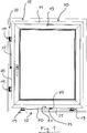
- window 10 comprises a frame 11 and a rotatable wing 13 and is intended for installation in a building opening 15.
- a positioning device 17 is provided, which will be described in more detail below.
- the positioning device 17 designed according to one embodiment of the invention comprises four spacer elements 19, of which two are arranged on the underside of the window frame 11 and two on the left side of the window frame 11, as shown.
- the window 10 is supported by the spacer elements 19 with respect to the border 20 of the building opening 15.
- the positioning device 17 comprises two inclination checking devices 25, one of which is arranged on the underside of the frame 11 and one on the left side of the frame 11 in the image.
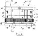
- Fig. 2 shows one of the spacer elements 19 in a side view.
- the spacer element 19 has an at least substantially cylindrical basic shape.
- the spacer element 19 can be fastened to the window frame 11 via a coupling section 27.
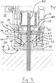
- 27 two resilient latching hooks 29 are provided on the coupling portion, as in the Section view according to Fig. 3 can be seen.
- the latching hooks 29 are arranged opposite as shown and engage behind respective profile projections 30 of the frame 11th
- the coupling portion 27 is supported on the border 20 of the building opening 15 via a first threaded spindle 31, a first spindle nut 32 cooperating therewith, a second threaded spindle 33, a second spindle nut 34 cooperating therewith and a contact portion 35.
- the abutment portion 35 is a support plate 37 having a flat abutment surface 38. On the support plate 37, a ball head 39 is formed, which is received in a ball head receptacle 40 of the spacer element 19. The coupling portion 27 and the abutment portion 35 are thus connected via a ball joint 41 with each other.
- the ball head receptacle 40 is formed in that component which also carries the first threaded spindle 31.
- the first spindle nut 32 is integrally formed with the second threaded spindle 33 as shown.
- the second spindle nut 34 is slidably supported on the coupling portion 27.
- the first threaded spindle 31 cooperates not only with the first spindle nut 32 but also with a lock nut 43 arranged adjacent thereto.
- Fig. 3 shows a state in which the first spindle nut 32 is turned up to the stop on the first threaded spindle 31 and equally the second spindle nut 34 is turned up to the stop on the second threaded spindle 33.
- the predetermined by the spacer element 19 distance between the coupling portion 27 and the contact portion 35 is minimal.
- the first spindle nut 32 is rotated relative to the first threaded spindle 31 so that it moves away from the stop, there is an increase in the distance between the coupling portion 27 and the abutment portion 35 and thus a shift Similarly, with a rotation of the second spindle nut 34 relative to the second threaded spindle 33 away from the stop a displacement of the frame 11 relative to the border 20 of the building opening 15 in the adjustment direction V takes place opposite the border 20 of the building opening 15.
- the first threaded spindle 31 and the first spindle nut 32 have a standard thread, while the second threaded spindle 33 and the second spindle nut 34 have a fine thread.
- the first spindle nut 32 and for a fine displacement of the frame 11, the second spindle nut 34 are rotated.
- the rotation of the spindle nuts 32, 34 can be done by direct manual means and in particular without tools, since the spindle nuts 32, 34 respective operating sections 44, 45 with handle features 46 (FIGS. Fig. 2 ) respectively.
- the lock nut 43 carries a peripheral corrugation 48.
- a user When positioning the window 10 within the building opening 15, a user can first make a coarse positioning by turning the first spindle nut 32 and then fix the position of the first spindle nut 32 by means of the lock nut 43. Then he can turn the second spindle nut 34 for fine positioning, wherein an undesired co-rotation of the first spindle nut 32 is prevented due to the lock nut 43.
- the lock nut 43 and the second spindle nut 34 are indicia 47 ( Fig. 2 ) are provided, which illustrate the sequence of steps in positioning.
- the spacer element 19 is provided for this purpose with a passage 80 for a screw 81.
- all components of the spacer element 19, in particular the coupling portion 27, the first threaded spindle 31, the first spindle nut 32, the second threaded spindle 33, the second spindle nut 34, the lock nut 43 and the support plate 37 made of a plastic, in particular from a regranulate ,
- the spacer element 19 can thus be manufactured particularly cost-effectively, so that it is suitable for use as a disposable article.
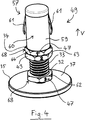
- the 4 to 6 show an alternative embodiment of a spacer element 49, which is constructed similar to that in the Fig. 1 to 3 shown spacer element 19, but designed for a lower height.
- the coupling portion 57 has a shaft 59 which, for insertion into a shank receptacle 58 provided on the frame 11 (FIG. Fig. 6 ) is trained.
- the shaft 57 has a cylindrical outer surface 60. From this stand two resilient latching tongues 61 ( Fig. 4 ). The resilient latching tongues 61 allow the coupling section 57 to snap into the shaft receptacle 58.
- spacer element 49 also has a first threaded spindle 31, a cooperating with this first spindle nut 32, a second threaded spindle 33, a cooperating with this second spindle nut 34, a lock nut 43 and a contact portion 35 in the form of a support plate 37.
- first threaded spindle 31 and the first spindle nut 32 have a fine thread
- second threaded spindle 33 and the second spindle nut 34 have a standard thread.
- the first threaded spindle 31 is formed integrally with the support plate 37.
- the second spindle nut 34 is further formed integrally with the shaft 59.
- the first spindle nut 32, the lock nut 43 and the second spindle nut 34 have respective actuating portions 62, 63, 64 which are provided with edge profiles 68. This allows twisting by means of a tool such as a fork wrench. Flags 47 are also provided. The adjustment of the second spindle nut 34 is to be made before the attachment of the coupling portion 57 on the window 10.
- the height of the in the 4 to 6 shown spacer element 49 is reduced in that the coupling portion 57 is partially disposed within the window frame 11 when the window 10 is installed.
- the edge profiles 68 require only a small height.
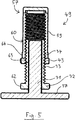
- Fig. 7 shows a further embodiment of a spacer element 69 of a positioning device 17 according to the invention.
- This is largely like the spacer element 49 according to 4 to 6 designed, however, wherein on the first screw 31, a form-fitting feature 83 is formed in the form of a hexagon socket, which is accessible through a recess 85 of the coupling portion 57. Since a corresponding recess 87 is also provided in the frame 11, the first threaded spindle 31 can also be rotated by means of a tool 88 if no lateral access to the gap between the frame 11 and the building opening 15 is possible.
- Each of the two inclination checking devices 25 comprises a strip-shaped main body 70, which is preferably made of a plastic, in particular of a regranulate. This has a flat contact surface 71 for applying the base body 70 to an outer surface of the frame 11. At the contact surface 71 are in Fig. 1 arranged invisible fasteners, which are in particular to similar latching hooks as in Fig. 3 for the spacer element 19 shown Snap hook 29 can act.
- the inclination test device 25 can be detachably attached to the frame 11.
- two dragonflies 75 are integrated, which are aligned offset by 90 ° to each other.
- the inclination of the window 10 can thus be continuously checked, without the need for a spirit level to be applied to the window frame 11 and held thereon.
- the inclination testers 25 are composed of inexpensive components, it is not absolutely necessary to remove them from the frame 11 before screwing and foaming the window 10. However, reuse of the tilt testers 25 may be desirable depending on the application. In principle, it is also possible to use a digital inclination indicator or the like instead of one or more dragonflies 75.
- the invention enables a considerably simplified installation of windows 10 and doors in building openings 15, wherein a particular advantage is that in a delivery of a window 10 with attached spacers 19, 49, 69 and inclination testing 25 in principle no own material and no own equipment must be provided by the fitter.
Landscapes
- Engineering & Computer Science (AREA)
- Mechanical Engineering (AREA)
- General Engineering & Computer Science (AREA)
- Civil Engineering (AREA)
- Structural Engineering (AREA)
- Architecture (AREA)
- Door And Window Frames Mounted To Openings (AREA)
Applications Claiming Priority (1)
| Application Number | Priority Date | Filing Date | Title |
|---|---|---|---|
| DE102017127119.8A DE102017127119A1 (de) | 2017-11-17 | 2017-11-17 | Vorrichtung zum Positionieren eines Fensters oder einer Tür |
Publications (3)
| Publication Number | Publication Date |
|---|---|
| EP3486420A2 true EP3486420A2 (fr) | 2019-05-22 |
| EP3486420A3 EP3486420A3 (fr) | 2019-08-14 |
| EP3486420B1 EP3486420B1 (fr) | 2020-12-30 |
Family
ID=64316395
Family Applications (1)
| Application Number | Title | Priority Date | Filing Date |
|---|---|---|---|
| EP18206244.8A Active EP3486420B1 (fr) | 2017-11-17 | 2018-11-14 | Procédé de positionnement d'une fenêtre ou d'une porte |
Country Status (2)
| Country | Link |
|---|---|
| EP (1) | EP3486420B1 (fr) |
| DE (1) | DE102017127119A1 (fr) |
Cited By (4)
| Publication number | Priority date | Publication date | Assignee | Title |
|---|---|---|---|---|
| CN110552588A (zh) * | 2019-09-20 | 2019-12-10 | 云南艺康装饰工程有限公司 | 一种门窗固定安装施工工艺 |
| EP3754144A1 (fr) * | 2019-06-18 | 2020-12-23 | SCHÜCO International KG | Entretoise, agencement de montage et procédé de montage d'une ferrure sur un profilé |
| CN114150978A (zh) * | 2021-12-16 | 2022-03-08 | 天津木艺家新材料科技有限公司 | 一种门窗及门窗安装方法 |
| CN116905936A (zh) * | 2023-06-27 | 2023-10-20 | 格满林(南京)新型材料科技有限公司 | 一种可拆卸自由定尺隐形半圆玻璃窗固定机构 |
Families Citing this family (1)
| Publication number | Priority date | Publication date | Assignee | Title |
|---|---|---|---|---|
| CN112983191B (zh) * | 2021-03-19 | 2022-11-18 | 北京润亚建设工程发展有限责任公司 | 一种门窗安装结构 |
Family Cites Families (17)
| Publication number | Priority date | Publication date | Assignee | Title |
|---|---|---|---|---|
| US4910876A (en) * | 1989-09-07 | 1990-03-27 | Channell John F | Level attachment |
| DE4421127A1 (de) * | 1994-06-16 | 1995-12-21 | Peter Pfeifer | Fensterrahmen |
| DE19531862A1 (de) * | 1995-08-30 | 1997-03-06 | Peter Pfeifer | Justiereinrichtung |
| DE19603413A1 (de) * | 1996-01-31 | 1997-08-07 | Hawik Innovative Baubeschlaege | Höhenverstelleinrichtung für einen unteren Abschluß von Türen oder Fenstern mit angesetzter Verbreiterung |
| WO1998001647A1 (fr) * | 1996-07-04 | 1998-01-15 | Soederstroem Kurt | Dispositif de fixation pour fixer de maniere reglable un cadre dans une ouverture de mur |
| DE29709238U1 (de) * | 1997-05-27 | 1997-10-16 | Schermann, Hans, 49835 Wietmarschen | Höhenregulierbares Befestigungssystem für bodenhohe Tür- und Fensterelemente |
| DE19722531A1 (de) * | 1997-05-30 | 1998-12-03 | Peter Willrich | Höhenverstelleinrichtung II |
| JPH1113346A (ja) * | 1997-06-25 | 1999-01-19 | Fukuju Oshima | 建具枠の垂直水平出し器 |
| DE29715991U1 (de) * | 1997-09-05 | 1997-11-20 | Glusa, Dieter, 06463 Meisdorf | Befestigungs- und Verkleidungssystem für Fensterelemente aus Kunststoff |
| DE19808194A1 (de) * | 1998-02-27 | 1999-09-09 | Fabricius | Justier- und Befestigungseinrichtung für den Fenstereinbau i Bauwerksöffnungen |
| DE19860269A1 (de) * | 1998-12-24 | 2000-06-29 | Bessey & Sohn | Montagekeil |
| AU2001241007A1 (en) * | 2000-03-07 | 2001-09-17 | Mtd Industries Ltd. | A window frame construction system and connector units for use therein |
| DE20311512U1 (de) * | 2003-07-25 | 2004-11-25 | Sfs Intec Holding Ag | Konsole zum Abstützen und Befestigen von Fenster- oder Türrahmen an der Begrenzung einer Wandöffnung |
| DE20311513U1 (de) * | 2003-07-25 | 2004-11-25 | Sfs Intec Holding Ag | Vorrichtung zum Abstützen und Befestigen von Fenster- oder Türrahmen an der Begrenzung einer Wandöffnung |
| DE202004007226U1 (de) * | 2004-05-06 | 2005-09-15 | Buschmann Thomas | Vorrichtung zur Montage eines Rahmens |
| DE202006012518U1 (de) * | 2006-08-14 | 2006-10-12 | Kneisen, Waldemar | Vorrichtung zum Justieren eines Baukörpers |
| DE102009056587A1 (de) * | 2009-11-27 | 2011-06-01 | Thomas Gerlach | Türzargenausrichter |
-
2017
- 2017-11-17 DE DE102017127119.8A patent/DE102017127119A1/de active Pending
-
2018
- 2018-11-14 EP EP18206244.8A patent/EP3486420B1/fr active Active
Cited By (5)
| Publication number | Priority date | Publication date | Assignee | Title |
|---|---|---|---|---|
| EP3754144A1 (fr) * | 2019-06-18 | 2020-12-23 | SCHÜCO International KG | Entretoise, agencement de montage et procédé de montage d'une ferrure sur un profilé |
| CN110552588A (zh) * | 2019-09-20 | 2019-12-10 | 云南艺康装饰工程有限公司 | 一种门窗固定安装施工工艺 |
| CN114150978A (zh) * | 2021-12-16 | 2022-03-08 | 天津木艺家新材料科技有限公司 | 一种门窗及门窗安装方法 |
| CN116905936A (zh) * | 2023-06-27 | 2023-10-20 | 格满林(南京)新型材料科技有限公司 | 一种可拆卸自由定尺隐形半圆玻璃窗固定机构 |
| CN116905936B (zh) * | 2023-06-27 | 2025-08-12 | 格满林(南京)新型材料科技有限公司 | 一种可拆卸自由定尺隐形半圆玻璃窗固定机构 |
Also Published As
| Publication number | Publication date |
|---|---|
| DE102017127119A1 (de) | 2019-05-23 |
| EP3486420B1 (fr) | 2020-12-30 |
| EP3486420A3 (fr) | 2019-08-14 |
Similar Documents
| Publication | Publication Date | Title |
|---|---|---|
| EP3486420B1 (fr) | Procédé de positionnement d'une fenêtre ou d'une porte | |
| EP2851497B1 (fr) | Dispositif de montage réglable pour un élément coulissant et dispositif coulissant | |
| EP3445935B1 (fr) | Installation de porte coulissante | |
| DE202013101519U1 (de) | Duschtür-Baugruppe | |
| EP2742199B1 (fr) | Système de fixation pour fixer une pièce sur une rainure d'une fenêtre, d'une porte ou analogue | |
| DE102016125683B3 (de) | Montagevorrichtung zum Einsetzen von Rahmenelementen in Wandöffnungen | |
| EP1394347B1 (fr) | Dispositif de guidage pour partitions coulissantes et élément de guidage élastique | |
| EP2792830B1 (fr) | Partie de ferrure avec élément de maintien | |
| EP3859105B1 (fr) | Dispositif de fermeture | |
| EP2078812A2 (fr) | Elément de recouvrement pour un rail de guidage | |
| DE102018100360A1 (de) | Rosettengarnitur | |
| EP3118404A1 (fr) | Charnière, notamment pour portes en matière synthétique et fenêtre en matière synthétique | |
| EP3577295B1 (fr) | Mécanisme d'entrainement pour meuble servant à déplacer une partie de meuble montée mobile | |
| DE10357589B3 (de) | Befestigungselement für Führungsschienen von Sonnenschutzanlagen | |
| EP1794053B1 (fr) | Dispositif de fixation d'un objet sur un rail | |
| DE202021100558U1 (de) | Verriegelungseinrichtung für ein Betätigungshandhabenpaar einer Tür | |
| DE20118506U1 (de) | Rahmen für einen Tür- oder Fensterflügel | |
| EP3379012A1 (fr) | Dispositif de guidage réglable pour un élément coulissant | |
| DE3345119A1 (de) | Vorrichtung zum verriegeln von tueren oder fenstern | |
| EP3336290A1 (fr) | Fermeture pour une gorge à armature à contre-dépouille d'une ferrures du type à tige d'entraînement | |
| EP3088639A1 (fr) | Dispositif destine a aligner des parties de ferrure a disposer en regard l'une de l'autre | |
| EP1270859A2 (fr) | Dispositif pour l'agencement mobile d'une porte coulissante | |
| WO2001034926A1 (fr) | Douille de correction angulaire pour l'adaptation de l'angle de montage de poignees quelconques sur des fenetres et des portes | |
| DE102019117862A1 (de) | Beschlagteil | |
| DE29803786U1 (de) | Vorrichtung zur genauen Ausrichtung eines Fenster- oder Türrahmens in einer Wandöffnung und dafür geeignete Führungsschiene |
Legal Events
| Date | Code | Title | Description |
|---|---|---|---|
| PUAI | Public reference made under article 153(3) epc to a published international application that has entered the european phase |
Free format text: ORIGINAL CODE: 0009012 |
|
| STAA | Information on the status of an ep patent application or granted ep patent |
Free format text: STATUS: THE APPLICATION HAS BEEN PUBLISHED |
|
| AK | Designated contracting states |
Kind code of ref document: A2 Designated state(s): AL AT BE BG CH CY CZ DE DK EE ES FI FR GB GR HR HU IE IS IT LI LT LU LV MC MK MT NL NO PL PT RO RS SE SI SK SM TR |
|
| AX | Request for extension of the european patent |
Extension state: BA ME |
|
| PUAL | Search report despatched |
Free format text: ORIGINAL CODE: 0009013 |
|
| AK | Designated contracting states |
Kind code of ref document: A3 Designated state(s): AL AT BE BG CH CY CZ DE DK EE ES FI FR GB GR HR HU IE IS IT LI LT LU LV MC MK MT NL NO PL PT RO RS SE SI SK SM TR |
|
| AX | Request for extension of the european patent |
Extension state: BA ME |
|
| RIC1 | Information provided on ipc code assigned before grant |
Ipc: F16B 5/02 20060101ALI20190709BHEP Ipc: E06B 1/60 20060101AFI20190709BHEP Ipc: F16B 21/08 20060101ALI20190709BHEP Ipc: E04F 21/00 20060101ALI20190709BHEP |
|
| STAA | Information on the status of an ep patent application or granted ep patent |
Free format text: STATUS: REQUEST FOR EXAMINATION WAS MADE |
|
| 17P | Request for examination filed |
Effective date: 20191023 |
|
| RBV | Designated contracting states (corrected) |
Designated state(s): AL AT BE BG CH CY CZ DE DK EE ES FI FR GB GR HR HU IE IS IT LI LT LU LV MC MK MT NL NO PL PT RO RS SE SI SK SM TR |
|
| GRAP | Despatch of communication of intention to grant a patent |
Free format text: ORIGINAL CODE: EPIDOSNIGR1 |
|
| STAA | Information on the status of an ep patent application or granted ep patent |
Free format text: STATUS: GRANT OF PATENT IS INTENDED |
|
| INTG | Intention to grant announced |
Effective date: 20200806 |
|
| GRAS | Grant fee paid |
Free format text: ORIGINAL CODE: EPIDOSNIGR3 |
|
| GRAA | (expected) grant |
Free format text: ORIGINAL CODE: 0009210 |
|
| STAA | Information on the status of an ep patent application or granted ep patent |
Free format text: STATUS: THE PATENT HAS BEEN GRANTED |
|
| AK | Designated contracting states |
Kind code of ref document: B1 Designated state(s): AL AT BE BG CH CY CZ DE DK EE ES FI FR GB GR HR HU IE IS IT LI LT LU LV MC MK MT NL NO PL PT RO RS SE SI SK SM TR |
|
| REG | Reference to a national code |
Ref country code: GB Ref legal event code: FG4D Free format text: NOT ENGLISH |
|
| REG | Reference to a national code |
Ref country code: AT Ref legal event code: REF Ref document number: 1350085 Country of ref document: AT Kind code of ref document: T Effective date: 20210115 |
|
| REG | Reference to a national code |
Ref country code: DE Ref legal event code: R096 Ref document number: 502018003469 Country of ref document: DE |
|
| REG | Reference to a national code |
Ref country code: IE Ref legal event code: FG4D Free format text: LANGUAGE OF EP DOCUMENT: GERMAN |
|
| PG25 | Lapsed in a contracting state [announced via postgrant information from national office to epo] |
Ref country code: NO Free format text: LAPSE BECAUSE OF FAILURE TO SUBMIT A TRANSLATION OF THE DESCRIPTION OR TO PAY THE FEE WITHIN THE PRESCRIBED TIME-LIMIT Effective date: 20210330 Ref country code: GR Free format text: LAPSE BECAUSE OF FAILURE TO SUBMIT A TRANSLATION OF THE DESCRIPTION OR TO PAY THE FEE WITHIN THE PRESCRIBED TIME-LIMIT Effective date: 20210331 Ref country code: RS Free format text: LAPSE BECAUSE OF FAILURE TO SUBMIT A TRANSLATION OF THE DESCRIPTION OR TO PAY THE FEE WITHIN THE PRESCRIBED TIME-LIMIT Effective date: 20201230 Ref country code: FI Free format text: LAPSE BECAUSE OF FAILURE TO SUBMIT A TRANSLATION OF THE DESCRIPTION OR TO PAY THE FEE WITHIN THE PRESCRIBED TIME-LIMIT Effective date: 20201230 |
|
| PG25 | Lapsed in a contracting state [announced via postgrant information from national office to epo] |
Ref country code: LV Free format text: LAPSE BECAUSE OF FAILURE TO SUBMIT A TRANSLATION OF THE DESCRIPTION OR TO PAY THE FEE WITHIN THE PRESCRIBED TIME-LIMIT Effective date: 20201230 Ref country code: SE Free format text: LAPSE BECAUSE OF FAILURE TO SUBMIT A TRANSLATION OF THE DESCRIPTION OR TO PAY THE FEE WITHIN THE PRESCRIBED TIME-LIMIT Effective date: 20201230 Ref country code: BG Free format text: LAPSE BECAUSE OF FAILURE TO SUBMIT A TRANSLATION OF THE DESCRIPTION OR TO PAY THE FEE WITHIN THE PRESCRIBED TIME-LIMIT Effective date: 20210330 |
|
| REG | Reference to a national code |
Ref country code: NL Ref legal event code: MP Effective date: 20201230 |
|
| PG25 | Lapsed in a contracting state [announced via postgrant information from national office to epo] |
Ref country code: HR Free format text: LAPSE BECAUSE OF FAILURE TO SUBMIT A TRANSLATION OF THE DESCRIPTION OR TO PAY THE FEE WITHIN THE PRESCRIBED TIME-LIMIT Effective date: 20201230 |
|
| REG | Reference to a national code |
Ref country code: LT Ref legal event code: MG9D |
|
| PG25 | Lapsed in a contracting state [announced via postgrant information from national office to epo] |
Ref country code: LT Free format text: LAPSE BECAUSE OF FAILURE TO SUBMIT A TRANSLATION OF THE DESCRIPTION OR TO PAY THE FEE WITHIN THE PRESCRIBED TIME-LIMIT Effective date: 20201230 Ref country code: PT Free format text: LAPSE BECAUSE OF FAILURE TO SUBMIT A TRANSLATION OF THE DESCRIPTION OR TO PAY THE FEE WITHIN THE PRESCRIBED TIME-LIMIT Effective date: 20210430 Ref country code: RO Free format text: LAPSE BECAUSE OF FAILURE TO SUBMIT A TRANSLATION OF THE DESCRIPTION OR TO PAY THE FEE WITHIN THE PRESCRIBED TIME-LIMIT Effective date: 20201230 Ref country code: SK Free format text: LAPSE BECAUSE OF FAILURE TO SUBMIT A TRANSLATION OF THE DESCRIPTION OR TO PAY THE FEE WITHIN THE PRESCRIBED TIME-LIMIT Effective date: 20201230 Ref country code: EE Free format text: LAPSE BECAUSE OF FAILURE TO SUBMIT A TRANSLATION OF THE DESCRIPTION OR TO PAY THE FEE WITHIN THE PRESCRIBED TIME-LIMIT Effective date: 20201230 Ref country code: CZ Free format text: LAPSE BECAUSE OF FAILURE TO SUBMIT A TRANSLATION OF THE DESCRIPTION OR TO PAY THE FEE WITHIN THE PRESCRIBED TIME-LIMIT Effective date: 20201230 |
|
| PG25 | Lapsed in a contracting state [announced via postgrant information from national office to epo] |
Ref country code: PL Free format text: LAPSE BECAUSE OF FAILURE TO SUBMIT A TRANSLATION OF THE DESCRIPTION OR TO PAY THE FEE WITHIN THE PRESCRIBED TIME-LIMIT Effective date: 20201230 |
|
| PG25 | Lapsed in a contracting state [announced via postgrant information from national office to epo] |
Ref country code: IS Free format text: LAPSE BECAUSE OF FAILURE TO SUBMIT A TRANSLATION OF THE DESCRIPTION OR TO PAY THE FEE WITHIN THE PRESCRIBED TIME-LIMIT Effective date: 20210430 |
|
| REG | Reference to a national code |
Ref country code: DE Ref legal event code: R097 Ref document number: 502018003469 Country of ref document: DE |
|
| PG25 | Lapsed in a contracting state [announced via postgrant information from national office to epo] |
Ref country code: AL Free format text: LAPSE BECAUSE OF FAILURE TO SUBMIT A TRANSLATION OF THE DESCRIPTION OR TO PAY THE FEE WITHIN THE PRESCRIBED TIME-LIMIT Effective date: 20201230 |
|
| PLBE | No opposition filed within time limit |
Free format text: ORIGINAL CODE: 0009261 |
|
| STAA | Information on the status of an ep patent application or granted ep patent |
Free format text: STATUS: NO OPPOSITION FILED WITHIN TIME LIMIT |
|
| PG25 | Lapsed in a contracting state [announced via postgrant information from national office to epo] |
Ref country code: DK Free format text: LAPSE BECAUSE OF FAILURE TO SUBMIT A TRANSLATION OF THE DESCRIPTION OR TO PAY THE FEE WITHIN THE PRESCRIBED TIME-LIMIT Effective date: 20201230 |
|
| 26N | No opposition filed |
Effective date: 20211001 |
|
| PG25 | Lapsed in a contracting state [announced via postgrant information from national office to epo] |
Ref country code: ES Free format text: LAPSE BECAUSE OF FAILURE TO SUBMIT A TRANSLATION OF THE DESCRIPTION OR TO PAY THE FEE WITHIN THE PRESCRIBED TIME-LIMIT Effective date: 20201230 |
|
| PG25 | Lapsed in a contracting state [announced via postgrant information from national office to epo] |
Ref country code: SI Free format text: LAPSE BECAUSE OF FAILURE TO SUBMIT A TRANSLATION OF THE DESCRIPTION OR TO PAY THE FEE WITHIN THE PRESCRIBED TIME-LIMIT Effective date: 20201230 |
|
| PG25 | Lapsed in a contracting state [announced via postgrant information from national office to epo] |
Ref country code: IS Free format text: LAPSE BECAUSE OF FAILURE TO SUBMIT A TRANSLATION OF THE DESCRIPTION OR TO PAY THE FEE WITHIN THE PRESCRIBED TIME-LIMIT Effective date: 20210430 |
|
| PG25 | Lapsed in a contracting state [announced via postgrant information from national office to epo] |
Ref country code: MC Free format text: LAPSE BECAUSE OF FAILURE TO SUBMIT A TRANSLATION OF THE DESCRIPTION OR TO PAY THE FEE WITHIN THE PRESCRIBED TIME-LIMIT Effective date: 20201230 |
|
| REG | Reference to a national code |
Ref country code: CH Ref legal event code: PL |
|
| PG25 | Lapsed in a contracting state [announced via postgrant information from national office to epo] |
Ref country code: LU Free format text: LAPSE BECAUSE OF NON-PAYMENT OF DUE FEES Effective date: 20211114 Ref country code: BE Free format text: LAPSE BECAUSE OF NON-PAYMENT OF DUE FEES Effective date: 20211130 |
|
| REG | Reference to a national code |
Ref country code: BE Ref legal event code: MM Effective date: 20211130 |
|
| PG25 | Lapsed in a contracting state [announced via postgrant information from national office to epo] |
Ref country code: LI Free format text: LAPSE BECAUSE OF NON-PAYMENT OF DUE FEES Effective date: 20211130 Ref country code: CH Free format text: LAPSE BECAUSE OF NON-PAYMENT OF DUE FEES Effective date: 20211130 |
|
| PG25 | Lapsed in a contracting state [announced via postgrant information from national office to epo] |
Ref country code: IE Free format text: LAPSE BECAUSE OF NON-PAYMENT OF DUE FEES Effective date: 20211114 |
|
| PG25 | Lapsed in a contracting state [announced via postgrant information from national office to epo] |
Ref country code: NL Free format text: LAPSE BECAUSE OF NON-PAYMENT OF DUE FEES Effective date: 20201230 Ref country code: CY Free format text: LAPSE BECAUSE OF FAILURE TO SUBMIT A TRANSLATION OF THE DESCRIPTION OR TO PAY THE FEE WITHIN THE PRESCRIBED TIME-LIMIT Effective date: 20201230 |
|
| GBPC | Gb: european patent ceased through non-payment of renewal fee |
Effective date: 20221114 |
|
| PG25 | Lapsed in a contracting state [announced via postgrant information from national office to epo] |
Ref country code: SM Free format text: LAPSE BECAUSE OF FAILURE TO SUBMIT A TRANSLATION OF THE DESCRIPTION OR TO PAY THE FEE WITHIN THE PRESCRIBED TIME-LIMIT Effective date: 20201230 Ref country code: HU Free format text: LAPSE BECAUSE OF FAILURE TO SUBMIT A TRANSLATION OF THE DESCRIPTION OR TO PAY THE FEE WITHIN THE PRESCRIBED TIME-LIMIT; INVALID AB INITIO Effective date: 20181114 |
|
| PG25 | Lapsed in a contracting state [announced via postgrant information from national office to epo] |
Ref country code: GB Free format text: LAPSE BECAUSE OF NON-PAYMENT OF DUE FEES Effective date: 20221114 |
|
| PG25 | Lapsed in a contracting state [announced via postgrant information from national office to epo] |
Ref country code: MK Free format text: LAPSE BECAUSE OF FAILURE TO SUBMIT A TRANSLATION OF THE DESCRIPTION OR TO PAY THE FEE WITHIN THE PRESCRIBED TIME-LIMIT Effective date: 20201230 |
|
| PG25 | Lapsed in a contracting state [announced via postgrant information from national office to epo] |
Ref country code: TR Free format text: LAPSE BECAUSE OF FAILURE TO SUBMIT A TRANSLATION OF THE DESCRIPTION OR TO PAY THE FEE WITHIN THE PRESCRIBED TIME-LIMIT Effective date: 20201230 |
|
| PG25 | Lapsed in a contracting state [announced via postgrant information from national office to epo] |
Ref country code: MT Free format text: LAPSE BECAUSE OF FAILURE TO SUBMIT A TRANSLATION OF THE DESCRIPTION OR TO PAY THE FEE WITHIN THE PRESCRIBED TIME-LIMIT Effective date: 20201230 |
|
| PGFP | Annual fee paid to national office [announced via postgrant information from national office to epo] |
Ref country code: DE Payment date: 20251119 Year of fee payment: 8 |
|
| PGFP | Annual fee paid to national office [announced via postgrant information from national office to epo] |
Ref country code: AT Payment date: 20251120 Year of fee payment: 8 |
|
| PGFP | Annual fee paid to national office [announced via postgrant information from national office to epo] |
Ref country code: IT Payment date: 20251125 Year of fee payment: 8 |
|
| PGFP | Annual fee paid to national office [announced via postgrant information from national office to epo] |
Ref country code: FR Payment date: 20251126 Year of fee payment: 8 |