EP3486542A2 - Kupplungsvorrichtung - Google Patents
Kupplungsvorrichtung Download PDFInfo
- Publication number
- EP3486542A2 EP3486542A2 EP18205289.4A EP18205289A EP3486542A2 EP 3486542 A2 EP3486542 A2 EP 3486542A2 EP 18205289 A EP18205289 A EP 18205289A EP 3486542 A2 EP3486542 A2 EP 3486542A2
- Authority
- EP
- European Patent Office
- Prior art keywords
- grip element
- openings
- dents
- coupling device
- plane
- Prior art date
- Legal status (The legal status is an assumption and is not a legal conclusion. Google has not performed a legal analysis and makes no representation as to the accuracy of the status listed.)
- Granted
Links
Images


Classifications
-
- B—PERFORMING OPERATIONS; TRANSPORTING
- B23—MACHINE TOOLS; METAL-WORKING NOT OTHERWISE PROVIDED FOR
- B23H—WORKING OF METAL BY THE ACTION OF A HIGH CONCENTRATION OF ELECTRIC CURRENT ON A WORKPIECE USING AN ELECTRODE WHICH TAKES THE PLACE OF A TOOL; SUCH WORKING COMBINED WITH OTHER FORMS OF WORKING OF METAL
- B23H9/00—Machining specially adapted for treating particular metal objects or for obtaining special effects or results on metal objects
- B23H9/14—Making holes
-
- F—MECHANICAL ENGINEERING; LIGHTING; HEATING; WEAPONS; BLASTING
- F16—ENGINEERING ELEMENTS AND UNITS; GENERAL MEASURES FOR PRODUCING AND MAINTAINING EFFECTIVE FUNCTIONING OF MACHINES OR INSTALLATIONS; THERMAL INSULATION IN GENERAL
- F16L—PIPES; JOINTS OR FITTINGS FOR PIPES; SUPPORTS FOR PIPES, CABLES OR PROTECTIVE TUBING; MEANS FOR THERMAL INSULATION IN GENERAL
- F16L21/00—Joints with sleeve or socket
- F16L21/02—Joints with sleeve or socket with elastic sealing rings between pipe and sleeve or between pipe and socket, e.g. with rolling or other prefabricated profiled rings
- F16L21/04—Joints with sleeve or socket with elastic sealing rings between pipe and sleeve or between pipe and socket, e.g. with rolling or other prefabricated profiled rings in which sealing rings are compressed by axially-movable members
-
- F—MECHANICAL ENGINEERING; LIGHTING; HEATING; WEAPONS; BLASTING
- F16—ENGINEERING ELEMENTS AND UNITS; GENERAL MEASURES FOR PRODUCING AND MAINTAINING EFFECTIVE FUNCTIONING OF MACHINES OR INSTALLATIONS; THERMAL INSULATION IN GENERAL
- F16L—PIPES; JOINTS OR FITTINGS FOR PIPES; SUPPORTS FOR PIPES, CABLES OR PROTECTIVE TUBING; MEANS FOR THERMAL INSULATION IN GENERAL
- F16L21/00—Joints with sleeve or socket
- F16L21/08—Joints with sleeve or socket with additional locking means
-
- B—PERFORMING OPERATIONS; TRANSPORTING
- B23—MACHINE TOOLS; METAL-WORKING NOT OTHERWISE PROVIDED FOR
- B23H—WORKING OF METAL BY THE ACTION OF A HIGH CONCENTRATION OF ELECTRIC CURRENT ON A WORKPIECE USING AN ELECTRODE WHICH TAKES THE PLACE OF A TOOL; SUCH WORKING COMBINED WITH OTHER FORMS OF WORKING OF METAL
- B23H1/00—Electrical discharge machining, i.e. removing metal with a series of rapidly recurring electrical discharges between an electrode and a workpiece in the presence of a fluid dielectric
- B23H1/02—Electric circuits specially adapted therefor, e.g. power supply, control, preventing short circuits or other abnormal discharges
Definitions
- the invention relates to a coupling device for a pipe, comprising a sleeve for receiving the pipe and at least one sealing member to provide a seal between the sleeve and the pipe, and a pressure member for applying a pressure to the sleeve and to the pipe.
- the instant invention aims to provide a solution or at least alleviate one or more of the above-mentioned problems, and to this end a coupling device, a method of manufacturing a grip element, and such a grip element are proposed according to the features of one or more of the appended claims.
- a coupling device which comprises a grip element extending along at least a part of the perimeter of the pipe, wherein the grip element is provided with dents pressed out of the plane of the grip element adjacent to slit like openings punched out of the grip element, and which comprises the novel feature that edges of the slit like openings are subjected to a peening operation.
- a suitable and preferable way to subject the edges of the slit like openings to the peening operation is to execute this operation prior to pressing the dents out of the plane of the grip element. This can be done with an appropriate peening tool.
- a feature that contributes to improving the effectiveness of the dents is that a frontal surface of a top of each dent is at an angle of approximately 90° with reference to the plane of the grip element.
- the invention is also embodied in a method for fabricating the grip element to be used in a coupling device according to the invention, wherein slit like openings are punched in a plate, and wherein in a forming process dents are pressed out of the plane of the plate adjacent to the openings.
- edges of the slit like openings are first subjected to a peening operation.
- the invention is also embodied in a grip element provided with dents pressed out of the plane of the grip element adjacent to slit like openings punched out of the grip element, wherein the slit like openings are subjected to a peening treatment.
- peening of the edges of the slit like openings is executed prior to pressing the dents out of the plane of the grip element.
- each grip element is supported by at least one pressure member, which pressure member is provided with protrusions that mate with the back of the dents that are pressed out of the plane of the corresponding grip element that is mounted on such pressure member.
- the protrusions mating with the back of the dents that are pressed out of the plane of the grip element is an effective means to counteract the earlier mentioned cheese slicer effect when the coupling device is used on softer pipes.
- This counteracting effect is particularly promoted in an embodiment wherein the protrusions of the pressure member block openings in the grip element that are present next to the dents.
- the construction of the protrusions that mate with the back of the dents also provides that forces acting on the grip element elements due to strains exerted by the pipe on the coupling device, will effectively be transferred to the pressure members and absorbed by the construction of the coupling device.
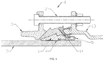
- FIG. 1 shows a coupling device 1 of the invention in a cross-sectional side view.
- the coupling device 1 comprises a sleeve 13 for receiving a pipe 2 and at least one sealing member 5 to provide a seal between the sleeve 13 and the pipe 2.
- the sealing member 5 may be attached to the sleeve 13 with a clip 14.
- the coupling device 1 comprises a pressure member 6 for applying a pressure to the sleeve 13 and to the pipe 2.
- Actuation means 3, 3' are provided to arrange that a pressure is applied to the pressure member 6, wherein a grip element 4 which extends along at least a part of the perimeter of the pipe 2 is supported by the pressure member 6. In this manner the grip element 4 is arranged to press on the pipe 2.
- the grip element 4 is formed with dents pressed out of the plane of the grip element.
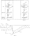
- FIGS 2A and 2B a prior art method is elucidated for fabricating a grip element to be used in a coupling device as shown in figure 1 .
- a punching tool 10 is used to provide slit like openings 8 in a plate 7. This is shown in figure 2A from top to bottom in an isometric view, in a side view, and in a cross-sectional view.
- figure 2B shows that in a subsequent step a pressing tool 11 is used to press dents 9 out of the plane of the plate 7 adjacent to the openings 8.
- Figure 2C shows on larger scale one of the resulting dents 9 which is pressed out of the plane of the plate 7.
- a frontal surface 9' of the top of the dent 9 is at an angle of between 50° and 70° with reference to the plane of the plate 7 that eventually forms the grip element.
- FIGS. 3A - 3C show the method of the invention for fabricating a grip element 4 to be used in a coupling device as shown in figure 1 .
- a punching tool 10 is used to provide slit like openings 8 in a plate 7 as shown in figure 3A from top to bottom in an isometric view, in a side view, and in a cross-sectional view.
- figure 2B shows that in a subsequent step edges 8' of the slit like openings 8 are subjected to an operation with a peening tool 12.
- Figure 2C shows that thereafter in a further process when the peening of the edges 8' of the slit like openings 8 is complete, a pressing tool 11 is used to press dents 9 out of the plane of the plate 7 adjacent to the openings 8 to form the eventual grip element 4.
- Figure 2D provides a detailed view on one of the resulting dents 9 which is pressed out of the plane of the plate 7.
- a frontal surface 9' of the top of the dent 9 is at an angle of approximately 90° with reference to the plane of the plate 7 of the grip element 4.
- FIG 4B shows separately in an isometric view a grip element 4 manufactured from a plate 7 as elucidated with reference to figures 3A - 3D , and a single pressure member 6.
- a multitude of such pressure members 6 together form a ring around the perimeter of the pipe 2 in the coupling device 1 which is referred to in figure 1 .
- a single pressure member 6 is shown in a cross-sectional view, wherein a single grip element 4 is mounted on the pressure member 6. It is however also possible that the pressure member 6 supports a number of grip elements, or that a number of pressure members support a single grip element.
- each single pressure member 6 supports a single grip element 4. Accordingly the pressure members 6 together support all grip elements 4 that collectively surround the pipe 2 shown in figure 1 . In the mounted condition the grip elements 4 thus extend along the entire perimeter of the pipe 2 which is connected to the coupling device 1.
- the shown pressure member 6 is provided with multiple protrusions 15 at the side facing the grip element 4.
- These protrusions 15 are designed to mate with the back of the dents 9 that are pressed out of the plane of the grip element 4, preferably in a manner that when the grip element 4 is mounted on the pressure member 6 as shown in figure 4A , the protrusions 15 of the pressure member 6 block openings 8 in the grip element 4 that are present next to the dents 9.
- This construction also provides that forces acting on the grip element 4 due to strains exerted by the pipe 2 on the coupling device 1, will effectively be transferred to the pressure member 6 and absorbed by the construction of the coupling device.
Landscapes
- Engineering & Computer Science (AREA)
- General Engineering & Computer Science (AREA)
- Mechanical Engineering (AREA)
- Physics & Mathematics (AREA)
- Thermal Sciences (AREA)
- Branch Pipes, Bends, And The Like (AREA)
- Joints With Sleeves (AREA)
- Quick-Acting Or Multi-Walled Pipe Joints (AREA)
- Measurement Of The Respiration, Hearing Ability, Form, And Blood Characteristics Of Living Organisms (AREA)
- Measuring Pulse, Heart Rate, Blood Pressure Or Blood Flow (AREA)
- Eye Examination Apparatus (AREA)
- Medicinal Preparation (AREA)
- Automatic Assembly (AREA)
- Mutual Connection Of Rods And Tubes (AREA)
- Accommodation For Nursing Or Treatment Tables (AREA)
Priority Applications (2)
| Application Number | Priority Date | Filing Date | Title |
|---|---|---|---|
| EP21177146.4A EP3892905B1 (de) | 2017-11-16 | 2018-11-09 | Kopplungsvorrichtung |
| DK21177146.4T DK3892905T3 (da) | 2017-11-16 | 2018-11-09 | Koblingsanordning |
Applications Claiming Priority (1)
| Application Number | Priority Date | Filing Date | Title |
|---|---|---|---|
| NL2019920A NL2019920B1 (en) | 2017-11-16 | 2017-11-16 | Coupling device |
Related Child Applications (2)
| Application Number | Title | Priority Date | Filing Date |
|---|---|---|---|
| EP21177146.4A Division EP3892905B1 (de) | 2017-11-16 | 2018-11-09 | Kopplungsvorrichtung |
| EP21177146.4A Division-Into EP3892905B1 (de) | 2017-11-16 | 2018-11-09 | Kopplungsvorrichtung |
Publications (3)
| Publication Number | Publication Date |
|---|---|
| EP3486542A2 true EP3486542A2 (de) | 2019-05-22 |
| EP3486542A3 EP3486542A3 (de) | 2019-08-07 |
| EP3486542B1 EP3486542B1 (de) | 2022-05-04 |
Family
ID=60813929
Family Applications (2)
| Application Number | Title | Priority Date | Filing Date |
|---|---|---|---|
| EP18205289.4A Active EP3486542B1 (de) | 2017-11-16 | 2018-11-09 | Greifring, verfahren zum herstellen eines greifrings und kupplungsvorrichtung mit solchen greifring |
| EP21177146.4A Active EP3892905B1 (de) | 2017-11-16 | 2018-11-09 | Kopplungsvorrichtung |
Family Applications After (1)
| Application Number | Title | Priority Date | Filing Date |
|---|---|---|---|
| EP21177146.4A Active EP3892905B1 (de) | 2017-11-16 | 2018-11-09 | Kopplungsvorrichtung |
Country Status (11)
| Country | Link |
|---|---|
| US (1) | US20200139465A2 (de) |
| EP (2) | EP3486542B1 (de) |
| JP (1) | JP7222667B2 (de) |
| AU (2) | AU2018264044B2 (de) |
| CA (1) | CA3024047C (de) |
| DK (2) | DK3892905T3 (de) |
| ES (2) | ES2915417T3 (de) |
| NL (1) | NL2019920B1 (de) |
| NZ (1) | NZ748357A (de) |
| PT (1) | PT3892905T (de) |
| SG (1) | SG10202008529PA (de) |
Cited By (3)
| Publication number | Priority date | Publication date | Assignee | Title |
|---|---|---|---|---|
| AT524049B1 (de) * | 2020-12-15 | 2022-02-15 | E Hawle Armaturenwerke Gmbh | Rohrverbindungsvorrichtung mit einem dichtungsträger |
| AT524050B1 (de) * | 2020-12-15 | 2022-02-15 | E Hawle Armaturenwerke Gmbh | Rohrverbindungsvorrichtung mit einem Sicherungskeil und einem Bremselement |
| EP4172525B1 (de) | 2020-06-30 | 2025-05-14 | Fucoli-Somepal - Fundição de Ferro S. A | Rohrverbindungs- und haltevorrichtung |
Families Citing this family (4)
| Publication number | Priority date | Publication date | Assignee | Title |
|---|---|---|---|---|
| US11199280B2 (en) * | 2017-04-19 | 2021-12-14 | Mueller Intemational, LLC | Joint restraint device |
| US11131412B2 (en) * | 2017-04-19 | 2021-09-28 | Mueller International, Llc | Joint restraint device |
| US10941887B2 (en) | 2017-07-13 | 2021-03-09 | Mueller International Llc | Wide range coupling |
| US11162621B2 (en) | 2019-02-04 | 2021-11-02 | Mueller International, Llc | Gland assembly |
Family Cites Families (14)
| Publication number | Priority date | Publication date | Assignee | Title |
|---|---|---|---|---|
| AT336970B (de) * | 1975-11-14 | 1977-06-10 | Hawle & Co Kg Flanschen Und Ar | Verbindungs- bzw. anschlussstuck fur glatte rohre, insbesondere kunststoffrohre |
| US4193616A (en) * | 1978-05-18 | 1980-03-18 | Dana Corporation | Quick connect fitting |
| JPH058392Y2 (de) * | 1988-03-18 | 1993-03-02 | ||
| NL1009734C2 (nl) * | 1998-07-24 | 2000-01-25 | Fischer Georg Waga Nv | Koppelinrichting en werkwijze voor de vervaardiging van een in een dergelijke koppelinrichting te gebruiken gripring. |
| NL1014758C2 (nl) * | 2000-03-27 | 2001-09-28 | Fischer Georg Waga Nv | Koppelinrichting en werkwijze voor de vervaardiging van een in een dergelijke koppelinrichting te gebruiken gripring. |
| JP2997671B1 (ja) * | 1998-08-18 | 2000-01-11 | 株式会社オンダ製作所 | 継 手 |
| GB2415735A (en) * | 2004-07-02 | 2006-01-04 | Julian Claude Peck | Bi-stable clip made from sheet material |
| NL1030404C2 (nl) | 2005-11-11 | 2007-05-14 | Fischer Georg Waga Nv | Koppelinrichting voor een buis. |
| NL2001726C2 (nl) * | 2008-06-26 | 2009-12-29 | Fischer Georg Waga Nv | Koppelinrichting en werkwijze voor de vervaardiging van een in een dergelijke koppelinrichting te gebruiken gripring. |
| NL2002683C2 (en) | 2009-03-30 | 2010-10-04 | Fischer Georg Waga Nv | A coupling device. |
| JP2011163473A (ja) * | 2010-02-10 | 2011-08-25 | Inoac Housing & Construction Materials Co Ltd | 管継手用ロックリング |
| NL2009953C2 (en) * | 2012-12-10 | 2014-06-11 | Fischer Georg Waga Nv | A coupling device for a tube. |
| CA2944828C (en) * | 2014-05-22 | 2020-10-27 | Georg Fischer Waga N.V. | Fitting for coupling to a pipe |
| NL2013426B1 (nl) * | 2014-09-05 | 2016-09-05 | Dyka B V | Verbindingssamenstel met trekvaste koppeling. |
-
2017
- 2017-11-16 NL NL2019920A patent/NL2019920B1/en active
-
2018
- 2018-11-07 SG SG10202008529PA patent/SG10202008529PA/en unknown
- 2018-11-09 PT PT211771464T patent/PT3892905T/pt unknown
- 2018-11-09 ES ES18205289T patent/ES2915417T3/es active Active
- 2018-11-09 EP EP18205289.4A patent/EP3486542B1/de active Active
- 2018-11-09 DK DK21177146.4T patent/DK3892905T3/da active
- 2018-11-09 ES ES21177146T patent/ES2939903T3/es active Active
- 2018-11-09 DK DK18205289.4T patent/DK3486542T3/da active
- 2018-11-09 EP EP21177146.4A patent/EP3892905B1/de active Active
- 2018-11-13 CA CA3024047A patent/CA3024047C/en active Active
- 2018-11-13 US US16/189,652 patent/US20200139465A2/en not_active Abandoned
- 2018-11-14 NZ NZ748357A patent/NZ748357A/en not_active IP Right Cessation
- 2018-11-14 AU AU2018264044A patent/AU2018264044B2/en active Active
- 2018-11-15 JP JP2018214712A patent/JP7222667B2/ja active Active
-
2020
- 2020-07-24 AU AU2020207878A patent/AU2020207878B2/en active Active
Cited By (6)
| Publication number | Priority date | Publication date | Assignee | Title |
|---|---|---|---|---|
| EP4172525B1 (de) | 2020-06-30 | 2025-05-14 | Fucoli-Somepal - Fundição de Ferro S. A | Rohrverbindungs- und haltevorrichtung |
| AT524049B1 (de) * | 2020-12-15 | 2022-02-15 | E Hawle Armaturenwerke Gmbh | Rohrverbindungsvorrichtung mit einem dichtungsträger |
| AT524050B1 (de) * | 2020-12-15 | 2022-02-15 | E Hawle Armaturenwerke Gmbh | Rohrverbindungsvorrichtung mit einem Sicherungskeil und einem Bremselement |
| AT524049A4 (de) * | 2020-12-15 | 2022-02-15 | E Hawle Armaturenwerke Gmbh | Rohrverbindungsvorrichtung mit einem dichtungsträger |
| AT524050A4 (de) * | 2020-12-15 | 2022-02-15 | E Hawle Armaturenwerke Gmbh | Rohrverbindungsvorrichtung mit einem Sicherungskeil und einem Bremselement |
| WO2022128910A1 (de) * | 2020-12-15 | 2022-06-23 | E. Hawle Armaturenwerke Gmbh | Rohrverbindungsvorrichtung mit einem sicherungskeil und einem bremselement |
Also Published As
| Publication number | Publication date |
|---|---|
| JP7222667B2 (ja) | 2023-02-15 |
| EP3892905B1 (de) | 2023-01-04 |
| BR102018072801A2 (pt) | 2019-07-09 |
| AU2018264044B2 (en) | 2020-07-30 |
| SG10202008529PA (en) | 2020-10-29 |
| NZ748357A (en) | 2020-01-31 |
| DK3486542T3 (da) | 2022-06-07 |
| JP2019090532A (ja) | 2019-06-13 |
| ES2939903T3 (es) | 2023-04-27 |
| CA3024047A1 (en) | 2019-05-16 |
| US20200139465A2 (en) | 2020-05-07 |
| NZ760536A (en) | 2021-10-29 |
| AU2018264044A1 (en) | 2019-05-30 |
| AU2020207878B2 (en) | 2022-06-16 |
| AU2020207878A1 (en) | 2020-08-13 |
| ES2915417T3 (es) | 2022-06-22 |
| EP3892905A1 (de) | 2021-10-13 |
| EP3486542B1 (de) | 2022-05-04 |
| US20190143433A1 (en) | 2019-05-16 |
| CA3024047C (en) | 2025-09-23 |
| EP3486542A3 (de) | 2019-08-07 |
| NL2019920B1 (en) | 2019-05-22 |
| PT3892905T (pt) | 2023-01-17 |
| DK3892905T3 (da) | 2023-02-06 |
Similar Documents
| Publication | Publication Date | Title |
|---|---|---|
| CA3024047C (en) | MATCHING DEVICE WITH GRIPPING ELEMENT | |
| EP2304296B1 (de) | Kopplungsvorrichtung und verfahren zur herstellung eines greifrings zur verwendung in solch einer kopplungsvorrichtung | |
| US11002331B2 (en) | Brake pad with preformed multi-layer friction pad and shim | |
| US20140000336A1 (en) | Method of cold forming a piece of sheet metal by bending or press moulding | |
| MX2019009701A (es) | Lamina de acero de alta resistencia. | |
| WO2014017436A1 (ja) | フランジ付き成形部材のプレス加工方法及びそれに用いる曲げ工具 | |
| US8387524B2 (en) | Apparatus and method for compensating for stress deformation in a press | |
| CA2277455C (en) | Coupling device and method for fabricating a grip ring to be used in such a coupling device | |
| MX2009007582A (es) | Hoja de material frio y metodo y herramienta para su fabricacion. | |
| MX372885B (es) | Metodo de estampacion y metodo para la fabricacion de producto estampado. | |
| TWI695746B (zh) | 具有切斷端面之表面處理鋼板的零件及其切斷加工方法 | |
| RU2774126C1 (ru) | Соединительное устройство | |
| US10184158B2 (en) | Method for hot forming, in particular for press hardening | |
| NZ760678A (en) | Sail construction | |
| NZ760678B2 (en) | Sea wave energy converter system to generate electricity using pioneer devices lined- up in particular arrangement | |
| KR20200120390A (ko) | 철제 도넛형 유체저장 용기의 케이스 제조용 드로잉 금형 | |
| RU2687636C1 (ru) | Декель высекального пресса для контрштампа ротационной высекальной машины и способ его изготовления | |
| BR102018072801B1 (pt) | Dispositivo acoplador para um tubo, método para fabricação de um elemento de aperto a ser usado em um dispositivo acoplador para um tubo e elemento de aperto para uso em um dispositivo acoplador para um tubo dotado com dentes | |
| JP6318036B2 (ja) | パンチ金型 | |
| AU719842B2 (en) | Die and punch for forming a joint therebetween | |
| AU737831B2 (en) | Die and punch for forming a joint therebetween | |
| JP2011224603A (ja) | 弾性プレス金型及び弾性プレス方法 | |
| CN105618590A (zh) | 厚板窄槽冲压模具带导向加强型冲头 | |
| MY131692A (en) | Tool for making joints between sheet-formed members,metal or non-metal | |
| JP2005279773A (ja) | 上ロール押え装置 |
Legal Events
| Date | Code | Title | Description |
|---|---|---|---|
| PUAI | Public reference made under article 153(3) epc to a published international application that has entered the european phase |
Free format text: ORIGINAL CODE: 0009012 |
|
| STAA | Information on the status of an ep patent application or granted ep patent |
Free format text: STATUS: THE APPLICATION HAS BEEN PUBLISHED |
|
| AK | Designated contracting states |
Kind code of ref document: A2 Designated state(s): AL AT BE BG CH CY CZ DE DK EE ES FI FR GB GR HR HU IE IS IT LI LT LU LV MC MK MT NL NO PL PT RO RS SE SI SK SM TR |
|
| AX | Request for extension of the european patent |
Extension state: BA ME |
|
| PUAL | Search report despatched |
Free format text: ORIGINAL CODE: 0009013 |
|
| AK | Designated contracting states |
Kind code of ref document: A3 Designated state(s): AL AT BE BG CH CY CZ DE DK EE ES FI FR GB GR HR HU IE IS IT LI LT LU LV MC MK MT NL NO PL PT RO RS SE SI SK SM TR |
|
| AX | Request for extension of the european patent |
Extension state: BA ME |
|
| RIC1 | Information provided on ipc code assigned before grant |
Ipc: F16L 21/08 20060101ALI20190703BHEP Ipc: F16L 21/04 20060101AFI20190703BHEP |
|
| STAA | Information on the status of an ep patent application or granted ep patent |
Free format text: STATUS: REQUEST FOR EXAMINATION WAS MADE |
|
| 17P | Request for examination filed |
Effective date: 20190829 |
|
| RBV | Designated contracting states (corrected) |
Designated state(s): AL AT BE BG CH CY CZ DE DK EE ES FI FR GB GR HR HU IE IS IT LI LT LU LV MC MK MT NL NO PL PT RO RS SE SI SK SM TR |
|
| STAA | Information on the status of an ep patent application or granted ep patent |
Free format text: STATUS: EXAMINATION IS IN PROGRESS |
|
| 17Q | First examination report despatched |
Effective date: 20210212 |
|
| GRAP | Despatch of communication of intention to grant a patent |
Free format text: ORIGINAL CODE: EPIDOSNIGR1 |
|
| STAA | Information on the status of an ep patent application or granted ep patent |
Free format text: STATUS: GRANT OF PATENT IS INTENDED |
|
| INTG | Intention to grant announced |
Effective date: 20220217 |
|
| GRAS | Grant fee paid |
Free format text: ORIGINAL CODE: EPIDOSNIGR3 |
|
| GRAA | (expected) grant |
Free format text: ORIGINAL CODE: 0009210 |
|
| STAA | Information on the status of an ep patent application or granted ep patent |
Free format text: STATUS: THE PATENT HAS BEEN GRANTED |
|
| AK | Designated contracting states |
Kind code of ref document: B1 Designated state(s): AL AT BE BG CH CY CZ DE DK EE ES FI FR GB GR HR HU IE IS IT LI LT LU LV MC MK MT NL NO PL PT RO RS SE SI SK SM TR |
|
| REG | Reference to a national code |
Ref country code: GB Ref legal event code: FG4D |
|
| REG | Reference to a national code |
Ref country code: CH Ref legal event code: EP |
|
| REG | Reference to a national code |
Ref country code: AT Ref legal event code: REF Ref document number: 1489384 Country of ref document: AT Kind code of ref document: T Effective date: 20220515 |
|
| REG | Reference to a national code |
Ref country code: DE Ref legal event code: R096 Ref document number: 602018034839 Country of ref document: DE |
|
| REG | Reference to a national code |
Ref country code: IE Ref legal event code: FG4D |
|
| REG | Reference to a national code |
Ref country code: NL Ref legal event code: FP |
|
| REG | Reference to a national code |
Ref country code: DK Ref legal event code: T3 Effective date: 20220531 |
|
| REG | Reference to a national code |
Ref country code: SE Ref legal event code: TRGR |
|
| REG | Reference to a national code |
Ref country code: ES Ref legal event code: FG2A Ref document number: 2915417 Country of ref document: ES Kind code of ref document: T3 Effective date: 20220622 |
|
| REG | Reference to a national code |
Ref country code: LT Ref legal event code: MG9D |
|
| PG25 | Lapsed in a contracting state [announced via postgrant information from national office to epo] |
Ref country code: HR Free format text: LAPSE BECAUSE OF FAILURE TO SUBMIT A TRANSLATION OF THE DESCRIPTION OR TO PAY THE FEE WITHIN THE PRESCRIBED TIME-LIMIT Effective date: 20220504 Ref country code: GR Free format text: LAPSE BECAUSE OF FAILURE TO SUBMIT A TRANSLATION OF THE DESCRIPTION OR TO PAY THE FEE WITHIN THE PRESCRIBED TIME-LIMIT Effective date: 20220805 Ref country code: FI Free format text: LAPSE BECAUSE OF FAILURE TO SUBMIT A TRANSLATION OF THE DESCRIPTION OR TO PAY THE FEE WITHIN THE PRESCRIBED TIME-LIMIT Effective date: 20220504 Ref country code: BG Free format text: LAPSE BECAUSE OF FAILURE TO SUBMIT A TRANSLATION OF THE DESCRIPTION OR TO PAY THE FEE WITHIN THE PRESCRIBED TIME-LIMIT Effective date: 20220804 Ref country code: PT Free format text: LAPSE BECAUSE OF FAILURE TO SUBMIT A TRANSLATION OF THE DESCRIPTION OR TO PAY THE FEE WITHIN THE PRESCRIBED TIME-LIMIT Effective date: 20220905 Ref country code: NO Free format text: LAPSE BECAUSE OF FAILURE TO SUBMIT A TRANSLATION OF THE DESCRIPTION OR TO PAY THE FEE WITHIN THE PRESCRIBED TIME-LIMIT Effective date: 20220804 Ref country code: LT Free format text: LAPSE BECAUSE OF FAILURE TO SUBMIT A TRANSLATION OF THE DESCRIPTION OR TO PAY THE FEE WITHIN THE PRESCRIBED TIME-LIMIT Effective date: 20220504 |
|
| PG25 | Lapsed in a contracting state [announced via postgrant information from national office to epo] |
Ref country code: RS Free format text: LAPSE BECAUSE OF FAILURE TO SUBMIT A TRANSLATION OF THE DESCRIPTION OR TO PAY THE FEE WITHIN THE PRESCRIBED TIME-LIMIT Effective date: 20220504 Ref country code: PL Free format text: LAPSE BECAUSE OF FAILURE TO SUBMIT A TRANSLATION OF THE DESCRIPTION OR TO PAY THE FEE WITHIN THE PRESCRIBED TIME-LIMIT Effective date: 20220504 Ref country code: LV Free format text: LAPSE BECAUSE OF FAILURE TO SUBMIT A TRANSLATION OF THE DESCRIPTION OR TO PAY THE FEE WITHIN THE PRESCRIBED TIME-LIMIT Effective date: 20220504 Ref country code: IS Free format text: LAPSE BECAUSE OF FAILURE TO SUBMIT A TRANSLATION OF THE DESCRIPTION OR TO PAY THE FEE WITHIN THE PRESCRIBED TIME-LIMIT Effective date: 20220904 |
|
| PG25 | Lapsed in a contracting state [announced via postgrant information from national office to epo] |
Ref country code: SM Free format text: LAPSE BECAUSE OF FAILURE TO SUBMIT A TRANSLATION OF THE DESCRIPTION OR TO PAY THE FEE WITHIN THE PRESCRIBED TIME-LIMIT Effective date: 20220504 Ref country code: SK Free format text: LAPSE BECAUSE OF FAILURE TO SUBMIT A TRANSLATION OF THE DESCRIPTION OR TO PAY THE FEE WITHIN THE PRESCRIBED TIME-LIMIT Effective date: 20220504 Ref country code: RO Free format text: LAPSE BECAUSE OF FAILURE TO SUBMIT A TRANSLATION OF THE DESCRIPTION OR TO PAY THE FEE WITHIN THE PRESCRIBED TIME-LIMIT Effective date: 20220504 Ref country code: EE Free format text: LAPSE BECAUSE OF FAILURE TO SUBMIT A TRANSLATION OF THE DESCRIPTION OR TO PAY THE FEE WITHIN THE PRESCRIBED TIME-LIMIT Effective date: 20220504 Ref country code: CZ Free format text: LAPSE BECAUSE OF FAILURE TO SUBMIT A TRANSLATION OF THE DESCRIPTION OR TO PAY THE FEE WITHIN THE PRESCRIBED TIME-LIMIT Effective date: 20220504 |
|
| REG | Reference to a national code |
Ref country code: DE Ref legal event code: R097 Ref document number: 602018034839 Country of ref document: DE |
|
| PLBE | No opposition filed within time limit |
Free format text: ORIGINAL CODE: 0009261 |
|
| STAA | Information on the status of an ep patent application or granted ep patent |
Free format text: STATUS: NO OPPOSITION FILED WITHIN TIME LIMIT |
|
| PG25 | Lapsed in a contracting state [announced via postgrant information from national office to epo] |
Ref country code: AL Free format text: LAPSE BECAUSE OF FAILURE TO SUBMIT A TRANSLATION OF THE DESCRIPTION OR TO PAY THE FEE WITHIN THE PRESCRIBED TIME-LIMIT Effective date: 20220504 |
|
| 26N | No opposition filed |
Effective date: 20230207 |
|
| PG25 | Lapsed in a contracting state [announced via postgrant information from national office to epo] |
Ref country code: SI Free format text: LAPSE BECAUSE OF FAILURE TO SUBMIT A TRANSLATION OF THE DESCRIPTION OR TO PAY THE FEE WITHIN THE PRESCRIBED TIME-LIMIT Effective date: 20220504 |
|
| PG25 | Lapsed in a contracting state [announced via postgrant information from national office to epo] |
Ref country code: MC Free format text: LAPSE BECAUSE OF FAILURE TO SUBMIT A TRANSLATION OF THE DESCRIPTION OR TO PAY THE FEE WITHIN THE PRESCRIBED TIME-LIMIT Effective date: 20220504 |
|
| P01 | Opt-out of the competence of the unified patent court (upc) registered |
Effective date: 20230529 |
|
| REG | Reference to a national code |
Ref country code: AT Ref legal event code: UEP Ref document number: 1489384 Country of ref document: AT Kind code of ref document: T Effective date: 20220504 |
|
| REG | Reference to a national code |
Ref country code: BE Ref legal event code: MM Effective date: 20221130 |
|
| PG25 | Lapsed in a contracting state [announced via postgrant information from national office to epo] |
Ref country code: LU Free format text: LAPSE BECAUSE OF NON-PAYMENT OF DUE FEES Effective date: 20221109 |
|
| PG25 | Lapsed in a contracting state [announced via postgrant information from national office to epo] |
Ref country code: IE Free format text: LAPSE BECAUSE OF NON-PAYMENT OF DUE FEES Effective date: 20221109 |
|
| PG25 | Lapsed in a contracting state [announced via postgrant information from national office to epo] |
Ref country code: BE Free format text: LAPSE BECAUSE OF NON-PAYMENT OF DUE FEES Effective date: 20221130 |
|
| PG25 | Lapsed in a contracting state [announced via postgrant information from national office to epo] |
Ref country code: HU Free format text: LAPSE BECAUSE OF FAILURE TO SUBMIT A TRANSLATION OF THE DESCRIPTION OR TO PAY THE FEE WITHIN THE PRESCRIBED TIME-LIMIT; INVALID AB INITIO Effective date: 20181109 |
|
| PG25 | Lapsed in a contracting state [announced via postgrant information from national office to epo] |
Ref country code: CY Free format text: LAPSE BECAUSE OF FAILURE TO SUBMIT A TRANSLATION OF THE DESCRIPTION OR TO PAY THE FEE WITHIN THE PRESCRIBED TIME-LIMIT Effective date: 20220504 |
|
| PG25 | Lapsed in a contracting state [announced via postgrant information from national office to epo] |
Ref country code: MK Free format text: LAPSE BECAUSE OF FAILURE TO SUBMIT A TRANSLATION OF THE DESCRIPTION OR TO PAY THE FEE WITHIN THE PRESCRIBED TIME-LIMIT Effective date: 20220504 |
|
| PG25 | Lapsed in a contracting state [announced via postgrant information from national office to epo] |
Ref country code: TR Free format text: LAPSE BECAUSE OF FAILURE TO SUBMIT A TRANSLATION OF THE DESCRIPTION OR TO PAY THE FEE WITHIN THE PRESCRIBED TIME-LIMIT Effective date: 20220504 |
|
| PG25 | Lapsed in a contracting state [announced via postgrant information from national office to epo] |
Ref country code: MT Free format text: LAPSE BECAUSE OF FAILURE TO SUBMIT A TRANSLATION OF THE DESCRIPTION OR TO PAY THE FEE WITHIN THE PRESCRIBED TIME-LIMIT Effective date: 20220504 |
|
| PG25 | Lapsed in a contracting state [announced via postgrant information from national office to epo] |
Ref country code: BG Free format text: LAPSE BECAUSE OF FAILURE TO SUBMIT A TRANSLATION OF THE DESCRIPTION OR TO PAY THE FEE WITHIN THE PRESCRIBED TIME-LIMIT Effective date: 20220504 |
|
| PG25 | Lapsed in a contracting state [announced via postgrant information from national office to epo] |
Ref country code: BG Free format text: LAPSE BECAUSE OF FAILURE TO SUBMIT A TRANSLATION OF THE DESCRIPTION OR TO PAY THE FEE WITHIN THE PRESCRIBED TIME-LIMIT Effective date: 20220504 |
|
| REG | Reference to a national code |
Ref country code: CH Ref legal event code: U11 Free format text: ST27 STATUS EVENT CODE: U-0-0-U10-U11 (AS PROVIDED BY THE NATIONAL OFFICE) Effective date: 20251201 |
|
| PGFP | Annual fee paid to national office [announced via postgrant information from national office to epo] |
Ref country code: NL Payment date: 20251119 Year of fee payment: 8 |
|
| PGFP | Annual fee paid to national office [announced via postgrant information from national office to epo] |
Ref country code: DE Payment date: 20251119 Year of fee payment: 8 |
|
| PGFP | Annual fee paid to national office [announced via postgrant information from national office to epo] |
Ref country code: GB Payment date: 20251121 Year of fee payment: 8 |
|
| PGFP | Annual fee paid to national office [announced via postgrant information from national office to epo] |
Ref country code: AT Payment date: 20251120 Year of fee payment: 8 |
|
| PGFP | Annual fee paid to national office [announced via postgrant information from national office to epo] |
Ref country code: IT Payment date: 20251125 Year of fee payment: 8 Ref country code: DK Payment date: 20251125 Year of fee payment: 8 |
|
| PGFP | Annual fee paid to national office [announced via postgrant information from national office to epo] |
Ref country code: FR Payment date: 20251126 Year of fee payment: 8 |
|
| PGFP | Annual fee paid to national office [announced via postgrant information from national office to epo] |
Ref country code: CH Payment date: 20251201 Year of fee payment: 8 Ref country code: SE Payment date: 20251119 Year of fee payment: 8 |
|
| PGFP | Annual fee paid to national office [announced via postgrant information from national office to epo] |
Ref country code: ES Payment date: 20251229 Year of fee payment: 8 |