EP3487655B1 - Fsw-werkzeug mit fester schulter - Google Patents
Fsw-werkzeug mit fester schulter Download PDFInfo
- Publication number
- EP3487655B1 EP3487655B1 EP17742228.4A EP17742228A EP3487655B1 EP 3487655 B1 EP3487655 B1 EP 3487655B1 EP 17742228 A EP17742228 A EP 17742228A EP 3487655 B1 EP3487655 B1 EP 3487655B1
- Authority
- EP
- European Patent Office
- Prior art keywords
- welding
- adapter
- tool
- shoulder
- fsw tool
- Prior art date
- Legal status (The legal status is an assumption and is not a legal conclusion. Google has not performed a legal analysis and makes no representation as to the accuracy of the status listed.)
- Active
Links
Images



Classifications
-
- B—PERFORMING OPERATIONS; TRANSPORTING
- B23—MACHINE TOOLS; METAL-WORKING NOT OTHERWISE PROVIDED FOR
- B23K—SOLDERING OR UNSOLDERING; WELDING; CLADDING OR PLATING BY SOLDERING OR WELDING; CUTTING BY APPLYING HEAT LOCALLY, e.g. FLAME CUTTING; WORKING BY LASER BEAM
- B23K20/00—Non-electric welding by applying impact or other pressure, with or without the application of heat, e.g. cladding or plating
- B23K20/12—Non-electric welding by applying impact or other pressure, with or without the application of heat, e.g. cladding or plating the heat being generated by friction; Friction welding
- B23K20/122—Non-electric welding by applying impact or other pressure, with or without the application of heat, e.g. cladding or plating the heat being generated by friction; Friction welding using a non-consumable tool, e.g. friction stir welding
-
- B—PERFORMING OPERATIONS; TRANSPORTING
- B23—MACHINE TOOLS; METAL-WORKING NOT OTHERWISE PROVIDED FOR
- B23K—SOLDERING OR UNSOLDERING; WELDING; CLADDING OR PLATING BY SOLDERING OR WELDING; CUTTING BY APPLYING HEAT LOCALLY, e.g. FLAME CUTTING; WORKING BY LASER BEAM
- B23K20/00—Non-electric welding by applying impact or other pressure, with or without the application of heat, e.g. cladding or plating
- B23K20/12—Non-electric welding by applying impact or other pressure, with or without the application of heat, e.g. cladding or plating the heat being generated by friction; Friction welding
- B23K20/122—Non-electric welding by applying impact or other pressure, with or without the application of heat, e.g. cladding or plating the heat being generated by friction; Friction welding using a non-consumable tool, e.g. friction stir welding
- B23K20/1245—Non-electric welding by applying impact or other pressure, with or without the application of heat, e.g. cladding or plating the heat being generated by friction; Friction welding using a non-consumable tool, e.g. friction stir welding characterised by the apparatus
-
- B—PERFORMING OPERATIONS; TRANSPORTING
- B23—MACHINE TOOLS; METAL-WORKING NOT OTHERWISE PROVIDED FOR
- B23K—SOLDERING OR UNSOLDERING; WELDING; CLADDING OR PLATING BY SOLDERING OR WELDING; CUTTING BY APPLYING HEAT LOCALLY, e.g. FLAME CUTTING; WORKING BY LASER BEAM
- B23K37/00—Auxiliary devices or processes, not specially adapted for a procedure covered by only one of the other main groups of this subclass
- B23K37/08—Auxiliary devices or processes, not specially adapted for a procedure covered by only one of the other main groups of this subclass for flash removal
Definitions
- the present invention relates to an upgrade kit for an FSW tool, an FSW tool equipped with such an upgrade kit and a method for adapting an FSW tool for a welding operation and an operating method for an FSW tool.
- FSW friction stir welding
- a FSW tool is accordingly a friction stir welding tool and an FSW process / method is a friction stir welding process / method.
- FSW processes are known in practice. They are usually used to connect two components or workpieces made of the same or matching materials.
- a welding pin set in rotation is applied to the surface of at least one of the components.
- the material of the at least one component is heated until it plasticizes, ie changes into a pasty state without melting.
- the welding pin is dipped into the material of the at least one workpiece, layers deeper in the material also being plasticized.
- the so-called welding shoulder or shoulder which comes into contact with the material of the at least one workpiece next to the welding pin when the welding pin is immersed.
- the shoulder can have the same or a different speed of rotation with respect to the welding pin. With respect to the at least one workpiece, the shoulder can execute a rotational movement or stand still.
- the FSW tool With the welding pin immersed in the material and the welding shoulder resting on the surface, the FSW tool is moved along the workpiece according to a desired welding line or welding path. In the process, more and more material of the workpiece is plasticized by the welding pin and possibly conveyed around the welding pin.
- the welding shoulder of the FSW tool forms the weld seam during the essentially translatory welding movement and, if necessary, also serves to apply contact pressure to the surface of the at least one workpiece, in particular essentially perpendicular to the surface or at a slight angle of incidence relative to the normal direction.
- the contact pressure and the covering of the plasticized zone with the welding shoulder ensure that the pasty material fills the entire depth of the weld seam and does not run away in an undesirable direction.
- a weld shoulder is defined as a surface area adjacent to a weld pin that covers the surface of during an FSW welding operation touches at least one workpiece in such a way that it comes into contact with the plasticized material.
- the welding shoulder can execute a rotational movement relative to the workpiece and a translational movement along a welding path.
- the translational and / or rotational movement (generally relative movement) between the welding shoulder and the workpiece can generate frictional heat that supports plasticization at least in certain areas.
- the plasticization can be effected exclusively or predominantly by the action of the welding pin.
- DE 10 2012 206 368 A1 discloses a friction stir spot welding device for joining flat workpieces lying on top of one another by means of friction stir spot welding (FSSW).
- a pressure application device with a pressure foot is provided on the FSSW welding tool. The pressure foot is pressed onto the upper workpiece during a spot welding process in order to lift it off the to prevent lower workpiece.
- An integral rotating welding tool with an end welding pin is dipped into the surface of the upper workpiece by a dipping mechanism. When immersed, the pressure foot is against the Pressed into the housing of the FSSW tool by force of a preload component. During a welding process, the pressure foot exhibits no movement relative to the workpieces. The contact surfaces of the pressure foot are outside the welding zone, ie they do not come into contact with plasticized material.
- a welding shoulder is provided exclusively on the one-piece rotating welding tool in an area next to the welding pin.
- the present disclosure is directed to FSW methods in which there is an essentially purely translational movement of the shoulder of the welding tool with respect to the at least one workpiece. These are also known as FSW procedures with standing shoulder or with fixed shoulder. If necessary, the FSW tool disclosed here can also be used for those FSW processes in which the welding shoulder and the welding pin are driven at different speeds of rotation (with one another or with respect to the workpiece).
- An FSW tool usually has components with a long service life that can be used over a large number of welding processes or the entire service life of the FSW tool without replacement.
- the FSW tool includes components that are subject to high wear during the welding process and that are therefore repaired or replaced after a certain number of welding processes have to. These components are referred to below as the upgrade kit.
- An upgrade kit for an FSW tool comprises an adapter that can be used in the tool holder of an FSW tool.
- the adapter is designed to receive a welding pin.
- the kit further comprises a shoulder cap which forms at least part of the welding shoulder.
- a welding pin is an optional part of the kit according to the present disclosure.
- the adapter, the welding pin and the shoulder cap can each be repaired or replaced individually or together after a certain number of welding processes.
- the tool holder is usually replaced less often or not at all. However, it can preferably be adapted to receive and fasten the adapter and / or the welding pin according to the present disclosure and possibly to the shape of the shoulder cap.
- the tool holder also forms an optional component of the kit according to the present disclosure.
- the shoulder cap has a passage opening for the welding pin and the adapter. It also has a welding shoulder area adjoining the passage opening on the outer surface.
- the welding shoulder area is a distal surface area of the shoulder cap, ie a surface area facing the welding point, which is physically involved in the welding process.
- the welding pin, the adapter and the passage opening in the shoulder cap preferably have a common reference axis, which is referred to below as the “longitudinal axis”.
- the longitudinal axis usually runs concentrically to the passage opening of the shoulder cap and is at the same time an axis of rotation for the rotary movement of the adapter and the welding pin.
- the adapter is mounted rotatably relative to the shoulder cap about a longitudinal axis running concentrically to the passage opening.
- the inner contour of the passage opening as well as a radial outer contour of the adapter at least at the end facing the welding point, i. at the distal end to be conical in shape.
- a substantially conical annular gap is formed between the shoulder cap and the adapter, in particular between the aforementioned inner contour and the radial outer contour.
- the conical shape on the inner contour of the passage opening and also the conical shape on the outside of the adapter are preferably selected such that they extend towards the inside of the FSW tool, i.e. to the dorsal side, widen.
- the opening angles of the two cones can be chosen to be identical or different so that the inside, i.e. to the dorsal side, tapering, widening or uniform clear widths of the annular gap in cross section.
- the conical shape of the annular gap or the inner contour of the passage opening and the outer contour of the adapter lead to various advantages. On the one hand is at a change in the positioning of the adapter in the direction of the longitudinal axis relative to the welding shoulder area changes the clear width of the annular gap. If the adapter is moved closer to the dorsal side, ie to the inside of the FSW tool, the opening width of the annular gap increases. If, on the other hand, the adapter is moved more to the distal side, ie more in the direction of the point of engagement of the FSW tool, the clear width of the annular gap is reduced.
- the adapter By positioning the adapter relative to the shoulder cap, a controlled setting of the clear width of the annular gap is possible in accordance with the opening angle of the conical contours.
- the width of the annular gap at the distal end can be adjusted to a size that is suitable for the respective welding operation. This was not possible with the previously known cylindrical gaps.
- the adapter and the tool holder are particularly preferably designed in such a way that positioning of the adapter in the direction of the longitudinal axis relative to the welding shoulder area is continuously adjustable so that the clear width of the annular gap can subsequently be adjusted continuously.
- the adapter and / or the welding pin are preferably designed to continuously adjust a positioning of the welding pin along the longitudinal axis and thus the depth of penetration of the pin into the material of the at least one workpiece.
- the setting of the positioning of the welding pin can particularly preferably take place independently of the setting of the positioning of the adapter. It is thus possible to specify low and high penetration depths for the welding pin in combination with wide or narrow gaps so that the set-up kit or the FSW tool can be flexibly adapted to any welding task. Finding the ideal combination of the depth of penetration of the welding pin and the width of the annular gap can be done in any way, for example by experiment, iterative optimization or analytical calculation / modeling.
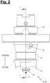
- Figures 1 and 2 show a FSW tool (10) with an upgrade kit (18) according to the present disclosure.
- the sectional view in Figure 1 is according to section line II in Figure 2 elected.
- the kit (18) comprises at least one adapter (12) and a shoulder cap (13).
- the adapter (12) is in a correspondingly adapted tool holder (15) on the FSW tool (10) can be used.
- a welding pin (11) can be inserted into the adapter (12).
- a (stepless) positioning (XA) of the adapter (12) and a (stepless) positioning (XP) of the welding pin (11) in the direction of a longitudinal axis (A) are provided.
- the welding pin (11), the adapter (12) and the tool holder (15) have a common longitudinal axis (A) about which the aforementioned components can be rotated together.
- the drive for the rotary movement can be generated in any way.
- the FSW tool (10) can preferably have its own rotary drive.
- the tool holder (15) can be permanently or detachably connected to an external drive, for example a spindle.
- the FSW tool (10) has a tool carrier (17) which can be designed as desired. Bearing points are preferably provided on the tool carrier (17) in order to receive the tool holder (15) rotatably about the longitudinal axis (A) and supported in the axial direction (A).
- the FSW tool (10) preferably also has a dome (16) which at least partially encloses an outside of the tool holder (15) and on which the shoulder cap (13) can be fixed in a rotationally fixed manner and supported in the axial direction (A).
- the FSW tool (17) is designed to receive the set-up (18) and to support or store it with respect to a common reference base.
- the FSW tool (10) is preferably designed as a manipulator-guided FSW tool that is used in an automated production process.
- the tool carrier (17) accordingly preferably has a flange element for connection to a manipulator hand and possibly to an output shaft of the manipulator.
- the manipulator can preferably be a five-, six- or seven-axis industrial robot.
- the manipulator hand can accordingly be a robot hand.
- the FSW tool with the kit (18), the dome (16), the tool holder (15) and the tool carrier (17) is preferably designed in such a way that the tool holder (15) with the adapter (12) is relative to the dome ( 16) is rotatably mounted and positioned on the tool carrier (17) in the direction of the longitudinal axis (A), and that the shoulder cap (13) is non-rotatably connected to the tool carrier (17) and is positioned in the direction of the longitudinal axis (A).
- the height of the adapter (12) in the direction of the longitudinal axis (A) and, on the other hand, the height of the welding pin (11) in the direction of the longitudinal axis (A) compared to the height of the welding shoulder area ( 13a) on the shoulder cap (13) can be adjusted to the desired size.
- the height of the shoulder cap (13) in the longitudinal direction (A) relative to the tool carrier (17) and / or the dome (16) can be adjusted, for example by inserting shims or other common construction variants.
- the shoulder cap (13) is an essentially rotationally symmetrical component which can be inserted into a correspondingly adapted receptacle at the distal end of the dome (16). Possibly.
- An anti-rotation device can be provided on the shoulder cap (13) and / or the dome (16), via which reaction forces from the welding process can be supported against the dome (16).
- the shoulder cap (13) is fixed to the dome (16) by a union nut (14).
- the union nut or another suitable fastening means for the shoulder cap (13) can also have a rotation lock.
- the shoulder cap (13) and the union nut (14) can be connected in one piece.
- the shoulder cap (13) can be fixed directly to the dome (16) by means of a thread or some other suitable construction means.
- shoulder cap (13) and union nut (14) have various advantages.
- the shoulder cap (13) is regularly repaired or replaced due to wear.
- the functional separation of the shoulder cap (13) and the union nut (14) enables a simpler and thus cheaper construction of the shoulder cap (13).
- the materials of the shoulder cap (13) and in particular the welding shoulder area (13a) on the one hand and the union nut (14) on the other hand, in particular the Fastening means (here thread) can be determined independently of each other. It is thus possible to provide shoulder caps (13) made of different materials for different welding requirements, each of which can be attached to the FSW tool (10) with the same or only a few variants of a union nut (14).
- FIG. 1 An enlarged view of the distal end of the FSW tool (10) is shown.
- the welding pin (11) and the adapter (12) are preferably set in a common rotary movement, in particular by driving the tool holder (15).
- the shoulder cap (13) with the welding shoulder area (13a) is not rotated with respect to the workpiece during the welding process, but only moved (together with the FSW tool) essentially along the intended welding path, which is usually a pure translational relative movement generated between the welding shoulder and the workpiece.
- a gap in particular an annular gap (21), is arranged between the distal end face (12b) and the welding shoulder area (13a) to allow the relative rotation between the welding pin (11) and the adapter (12) on the one hand and the shoulder cap (13) on the other to enable.
- the annular gap is delimited outward in the radial direction by an inner contour (20a) of the passage opening (20) on the shoulder cap (13).
- the annular gap (21) is delimited by a radial outer contour (12a) of the adapter (12).
- the annular gap (21) is preferably designed to be rotationally symmetrical to the longitudinal axis (A).
- the inner contour (20a) of the passage opening (20) and the radial outer contour (12a) of the adapter (12) are conically shaped at least at the distal end.
- the conical shape preferably extends over the entire length of the overlap between the inner contour (20a) and the outer contour (12a).
- the mean diameter of the annular gap (21) preferably increases in the dorsal direction along the longitudinal axis (A).
- the mean diameter of the annular gap (21) is smaller at the distal end than at the dorsal end.
- the clear width (D) (compare Figure 6 ) is therefore the same over the entire length of the annular gap (21) or increases in the dorsal direction.
- the mean diameter of the annular gap (21) can decrease in the dorsal direction along the longitudinal axis (A).
- the opening angle (W) of the conical inner contour (20a) has an amount between 10 ° and 45 ° (angular degrees). Furthermore, the opening angle (W) of the conical radial outer contour (12a) of the adapter (12) with respect to the longitudinal axis (A) is preferably between 10 ° and 45 ° (angular degrees). In other words, the opening angle (W) of the conical contour (20a) and the conical radial outer contour (12a) preferably have the same dimension. Alternatively, the opening angles can be slightly different.
- the opening angle of the inner contour (20a) is selected to be somewhat larger than the opening angle of the conical radial outer contour (12a), so that the clear width (D) of the annular gap (21) in the dorsal direction along the longitudinal axis (A) increases.
- the positioning (XA) can be done by any means and construction elements.
- One or more setting means for fixing the axial position of the adapter (12) and / or the welding pin (11) are preferably arranged on the tool holder (15). These setting means can in particular be designed as adjustable stops and / or as clamping devices. According to the examples in Figures 3 and 4 the setting means are designed as one or more clamping screws (not shown) which can be inserted into the tool holder (15) in the radial direction.
- FIGs 3 and 4 show preferred embodiments of a welding pin (11) and an adapter (12).
- the welding pin (11) and the adapter (12) can each have a shaft (25, 27) which is preferably rotationally symmetrical / cylindrical in shape.
- One or more flattened areas (26, 29) can be provided on this shaft (25, 27) which interact with the adjustment means mentioned above, in particular for producing a clamping connection.
- the aforementioned one or more clamping screws or other suitable locking means, which interact with the flattened areas (26, 29), can be arranged on the tool holder (15).
- the adapter (12) has a lateral opening (28) through which a clamping screw or other suitable adjustment means can reach in order to come into contact with the flat (16) on the welding pin (11).
- movable stops or adjusting screws arranged in the direction of the longitudinal axis (A) can be provided on the tool holder (15) and / or the adapter (12) to facilitate the positioning (XA) of the adapter (12) and / or to define the positioning (XP) of the welding pin (11) along the longitudinal axis (A).
- the conical radial outer contour (12a) of the adapter (12) and the conical inner contour (20a) of the shoulder cap (13) can be essentially smooth, ie they can form a regular conical surface (cf. Figures 5 and 6 ).
- first guide structure (22) can be arranged on the conical, radial outer contour (12a) of the adapter (12), which when the adapter (12) and the shoulder cap (13) rotates relative to one another in the annular gap (21 ) material located causes a conveying force in the direction of the longitudinal axis (A).
- a corresponding (first) guide structure can be arranged on the inner contour (20a) of the passage opening (20) (not shown) ).
- the (first) guide structure (22) can be designed in such a way that it brings about a conveying force in the direction of the outside of the FSW tool, ie in the distal direction.
- the conductive structure (22) causes material to be driven out during a welding process, which material possibly penetrates into the annular gap (21).
- a self-cleaning function is created for the annular gap (21), in which material is conveyed out of the gap again in the direction of the welding point.
- an intended direction of rotation for rotating the adapter (12) with respect to the shoulder cap (13) to produce a conveying force in the distal direction is indicated by a rotation arrow.
- the (first) guide structure (22) can be designed to bring about a conveying force in the direction of the inside of the FSW tool, ie in the dorsal direction.
- the annular gap (21) is self-cleaning, although the material is conveyed away to the inside. It is accordingly advantageous if a chamber (30) is arranged at the inner end of the annular gap (21) in the assembled state of the kit (cf. Fig. 6 ), which is designed to accommodate welding material passing through the annular gap (21).
- FIG 4 an embodiment variant is shown in which the aforementioned first guide structure (22) and additionally a second (inner / dorsal) guide structure (23) are arranged on the conical radial outer contour (12a) of the adapter (12).
- the second guide structure (23) is located closer to the inside of the FSW tool in the longitudinal direction (A), ie at the dorsal end of the conical radial outer contour (12a).
- the first and the second conductive structure (22, 23) are aligned opposite to one another.
- the first guide structure (22) can bring about a delivery force in the distal direction, ie towards the outside of the FSW tool, while the second guide contour (23) creates a delivery force in the dorsal direction, ie towards the inside of the FSW tool.
- the first guide structure thus serves to counteract the penetration of pasty material into the annular gap (21) or to convey material that has entered back to the welding point. If, however, too large an amount of material enters the annular gap while overcoming the first conveying force, the second guide structure causes emptying to the inside, in particular in the direction of the aforementioned chamber (30). Due to the size ratio between the first and the second guide contour (22, 23) and their characteristics, the conveying effects in the distal and dorsal direction can be adapted according to the process requirements.
- the aforementioned guide structures (22, 23) can have any design.
- a helical or thread-shaped recess in the conical radial outer contour (12a) for forming a guide structure (22, 23) is shown as an example.
- a different shape of a helix embedded or attached to the surface, attached blade surfaces or other suitable contours can be used.
- a cleaning effect for the annular gap (21) can alternatively or additionally be achieved by other measures.
- a pressure difference can be generated between the inner or dorsal opening and the outer or distal opening of the annular gap (21), which, as required, generates a conveying effect in the distal or dorsal direction on a material located in the annular gap (21).
- the FSW tool can do this be made pressure-tight with respect to the annular gap (21) and have a pressure source.
- the pressure source can preferably be controllable or regulatable.
- the shoulder cap (13) envelops the distal end region of the tool holder (15) in a pressure-tight manner. Furthermore, the shoulder cap (13) and the dome (16) can jointly enclose the tool holder (15) in a pressure-tight manner. In this way, a fluid passage or pressure line passage which can be pressurized is formed in the space between the shoulder cap (13) and the dome (16) on the one hand and the tool holder (15) and the adapter (12) on the other hand.
- the FSW tool (10) can preferably have a pressure source, in particular a positive pressure source, at the dorsal end.
- a conveying force directed outwards is exerted on a material located in the annular gap (21).
- the overpressure source can preferably be controlled or regulated in order to establish a balance between the reaction forces from the welding process, through which a material is conveyed into the annular gap (21), on the one hand, and the conveying forces used in the distal direction to clean the conveying gap on the other.
- the pressure source can be designed to generate a negative pressure.
- a conveying force can be exerted on any material located in the annular gap, which pulls the material inward, i.e. acts in the dorsal direction for cleaning.
- the generation of an overpressure can preferably be used during a welding operation in order to reduce or avoid the penetration of pasty material into the annular gap.
- the generation of a negative pressure can preferably be used after a welding operation in order to suck off any material present in the annular gap inwards. If necessary alternating overpressure and underpressure can be generated in order to generate a conveying force that changes in direction (inward / outward). A changing conveying force can be helpful in loosening material components that are already hardening.
- An operating method for an FSW tool with a pressure source for performing a welding operation preferably comprises the following steps: Feeding the FSW tool (10) to at least one workpiece, so that the welding pin (11) comes into contact with a workpiece surface. Execution of an immersion movement along the longitudinal axis (A) of the welding pin (11) until the auxiliary shoulder (12b) on the adapter (12) and / or the welding shoulder area (13a) of the shoulder cap (13) comes into contact with the workpiece surface . During and after the immersion movement, part of the material of the at least one workpiece is plasticized. The plasticization can be supported by the contact between the welding shoulder area (13a) and the workpiece and / or between the auxiliary shoulder (12b) and the workpiece.
- the pressure source of the FSW tool (10) is actuated in order to generate a pressure inside the FSW tool (10) and to exert a conveying force on a plasticized material that may be in the Annular gap (21) is located.
- the delivery force can be directed inwards (dorsal) or outwards (distal). Alternatively, the direction of the conveying force can change.
- the FSW tool (10) is preferably guided with an essentially translatory movement along a provided welding path.
- the plasticized material is preferably shaped by the auxiliary shoulder (12b) and / or the welding shoulder area (13a), in particular to form a desired seam shape or seam surface.
- the dome (16) can have one or more openings (24) arranged transversely to the longitudinal axis (A) through which the one or more setting means for determining the axial position (XA, XP) of the adapter (12) and / or the welding pin ( 12) are accessible.
- corresponding closure caps can be provided for these openings (24).
- FIG Figures 5 and 6 a preferred method for adapting the FSW tool (10) or an upgrade kit (18) for a welding operation or a welding process is explained.
- the adapter (12) can according to the Figures 5 and 6 in the embodiment shown on the left have a distal excess length so that in the basic state it protrudes beyond the height of the welding shoulder area (13a) in the distal direction along the longitudinal axis (A). If the adapter (12) is moved along the longitudinal axis (A) maximally in the distal direction until the conical radial outer contour (12a) comes to rest on the inner contour (20a) of the passage opening (20), the end face (12b) of the Adapters (12) protrude in the distal direction beyond the welding shoulder area (13a) of the shoulder cap (13). In this position, the clear width (D) of the annular gap (21) is reduced to a minimum, in particular equal to zero.
- the position (XA) of the adapter (12) can be set in the longitudinal direction (A) relative to the position of the shoulder cap (13) or relative to this starting position such that the width (D) of the annular gap (21) is set to a desired Dimension is determined, in particular in that the adapter (12) is displaced relative to the aforementioned starting position in the dorsal direction along the longitudinal axis (A).
- the adapter (12) can be adjusted relative to the shoulder cap (13) in the Set longitudinal direction (A), in particular clamped and / or supported on a stop.
- the overhang of the adapter (12) can then be shortened at the distal end.
- a shortening (12c) of the adapter (12) is shown by such an amount that the height of the end face (12b) of the adapter (12) in the direction of the longitudinal axis (A) is adapted to the height of the welding shoulder area (13a) .
- the adapter (12) is shortened in order to set a height difference between the end face (12b) and the welding shoulder area (13a) to a desired level.
- the shoulder cap (13) can be shortened at least in the area of the welding shoulder area (13a) in order to set a height difference between the end face (12b) and the welding shoulder area (13a) to a desired level. Accordingly, an adapter (12) can be provided without the above-mentioned protrusion.
- the end face (12b) of the adapter (12) can in particular take place in such a way that a uniform height of the welding shoulder area (13a) and the end face (12b) of the adapter (12) is produced in the direction of the longitudinal axis (A).
- a shortening can take place in such a way that the surface dimensions of the welding shoulder area (13a) and / or the end face (12b) can be adjusted to a desired dimension or a desired area ratio.
- the shortening of the adapter (12) and / or the shoulder cap (13) can be achieved in any way, in particular by a machining process such as milling, turning or grinding. Possibly. a filler material can be introduced into the annular gap (21) for the period of the shortening in order to prevent chips or other undesired foreign particles from penetrating into the annular gap (21) during the shortening.
- the shoulder cap (13) can have one or more openings or recesses through which, for example, material conveyed to the inside of the FSW tool (10) can escape to the outside again.
- the shoulder cap (13) can in particular be bow-shaped or perforated disk-shaped.
- the welding pin (11) can have any design. In particular, it can be a standardized tool.
- a conversion kit (18) for an FSW tool (10) can, in addition to the shoulder cap (13) and the adapter (12), one or more welding pins (11) and, if necessary, one or more tool holders (15) and setting means for determining the position the adapter (12) and / or the welding pin (11).
- the dome (16) can be connected in one piece to the tool carrier (17).
- the distal end face (12a) of the adapter (12) can serve as an auxiliary shoulder. It is usually moved at the same speed of rotation as the welding pin (11).
- the size (area) of the auxiliary shoulder can be set to the desired size by shortening the adapter (12) or its protrusion, regardless of the setting of the width (D) of the annular gap (21) and the depth of penetration of the welding pin (11) .
Landscapes
- Engineering & Computer Science (AREA)
- Mechanical Engineering (AREA)
- Physics & Mathematics (AREA)
- Optics & Photonics (AREA)
- Pressure Welding/Diffusion-Bonding (AREA)
- Lining Or Joining Of Plastics Or The Like (AREA)
- Resistance Welding (AREA)
Description
- Die vorliegende Erfindung betrifft einen Rüstsatz für ein FSW-Werkzeug, ein mit einem solchen Rüstsatz ausgestattetes FSW-Werkzeug sowie ein Verfahren zur Anpassung eines FSW-Werkzeugs für eine Schweißoperation und ein Betriebsverfahren für ein FSW-Werkzeug.
- Im Rahmen der vorliegenden Offenbarung wird die Abkürzung "FSW" für Rührreibschweißen (englisch: friction stir welding) verwendet. Ein FSW-Werkzeug ist demnach ein Rührreibschweiß-Werkzeug und ein FSW-Prozess / -Verfahren ist ein Rührreibschweiß-Prozess / -Verfahren.
- FSW-Verfahren sind in der Praxis in verschiedenen Ausführungen bekannt. Sie werden in der Regel dazu verwendet, zwei Bauteile bzw. Werkstücke aus gleichen oder zueinander passenden Materialien miteinander zu verbinden. Ein in Drehbewegung versetzter Schweißstift wird zu Beginn eines FSW-Prozesses an die Oberfläche zumindest eines der Bauteile angesetzt. Durch die Reibung zwischen dem Stift und der Oberfläche wird das Material des mindestens einen Bauteils solange erwärmt, bis es plastifiziert, d.h. in einen pastösen Zustand übergeht, ohne dabei aufzuschmelzen. Der Schweißstift wird in das Material des mindestens einen Werkstücks eingetaucht, wobei auch tiefer im Material liegende Schichten plastifiziert werden.
- Am dorsalen Ende des Schweißstifts ist eine in Radialrichtung überstehende Fläche, die sogenannte Schweißschulter oder Schulter angeordnet, die beim Eintauchen des Schweißstifts mit dem Material des mindestens einen Werkstücks neben dem Schweißstift zur Anlage kommt. Die Schulter kann in Bezug auf den Schweißstift dieselbe oder eine unterschiedliche Rotationsgeschwindigkeit haben. In Bezug auf das mindestens eine Werkstück kann die Schulter eine Rotationsbewegung ausführen oder stillstehen.
- Das FSW-Werkzeug wird mit dem in das Material eingetauchten Schweißstift und der an der Oberfläche anliegenden Schweißschulter an dem Werkstück gemäß einer gewünschten Schweißlinie oder Schweißbahn entlangbewegt. Dabei wird durch den Schweißstift immer weiteres Material des Werkstücks plastifiziert und ggf. um den Schweißstift herum gefördert. Die Schweißschulter des FSW-Werkzeugs formt während der im Wesentlichen translatorischen Schweißbewegung die Schweißnaht und dient ggf. ferner zur Auswirkung eines Anpressdrucks auf die Oberfläche des mindestens einen Werkstücks, insbesondere im Wesentlichen senkrecht zur Oberfläche oder mit einem leichten Anstellwinkel gegenüber der Normalrichtung. Durch den Anpressdruck und die Überdeckung der plastifizierten Zone mit der Schweißschulter wird erreicht, dass das pastöse Material die vollständige Tiefe der Schweißnaht ausfüllt und nicht in einer unerwünschten Richtung wegläuft.
- Eine Schweißschulter ist beim Rührreibschweißen definiert als ein Oberflächenbereich neben einem Schweißstift, der während einer FSW-Schweißoperation die Oberfläche von zumindest einem Werkstück derart berührt, dass sie in Kontakt mit dem plastifizierten Material kommt. Die Schweißschulter kann relativ zu dem Werkstück eine Rotationsbewegung sowie entlang einer Schweißbahn eine Translationsbewegung ausführen. Durch die Translations- und/oder Rotationsbewegung (allgemein Relativbewegung) zwischen Schweißschulter und Werkstück kann Reibungswärme erzeugt werden, die zumindest bereichsweise die Plastifizierung unterstützt. Alternativ kann die Plastifizierung ausschließlich oder weit überwiegend durch die Einwirkung des Schweißstifts bewirkt werden.
- Aus der
WO 2008/082420 A1 , welche als nächstliegender Stand der Technik angesehen wird und den Oberbegriff des Anspruchs 1 bildet, ist ein Rüstsatz für ein FSW-Werkzeug bekannt mit einem Adapter, der zylindrisch geformt ist. - Aus
US 8,006,890 B2 undUS 8, 814, 027 B2 sind FSW-Werkzeuge bekannt, bei denen ein Spalt zwischen dem rotierenden und jeweils einstückig ausgeführten Schweißstift und einem angrenzenden Bauteil, das die Schweißschulter bildet, jedenfalls an dem zur Schweißstelle weisenden Ende zylindrisch geformt ist. -
DE 10 2012 206 368 A1 offenbart eine Rührreib-Punktschweißvorrichtung zum Verbinden von übereinander liegenden flachen Werkstücken mittels einer Rührreib-Punktschweißung (Friction Stir Spot Welding - FSSW). An dem FSSW-Schweißwerkzeug ist eine Druckaufbringeinrichtung mit einem Druckfuß vorgesehen. Der Druckfuß wird während eines Punktschweißvorgangs auf das obere Werkstück gepresst, um ein Abheben von dem unteren Werkstück zu verhindern. Ein einstückig ausgebildetes rotierendes Schweißwerkzeug mit einem endseitigen Schweißstift wird durch einen Tauchmechanismus in die Oberfläche des oberen Werkstücks eingetaucht. Beim Eintauchen wird der Druckfuß gegen die Kraft einer Vorspannkomponente in das Gehäuse des FSSW-Werkzeugs hineingedrückt. Während eines Schweißvorgangs weist der Druckfuß keine Relativbewegung zu den Werkstücken auf. Die Kontaktflächen des Druckfußes liegen außerhalb der Schweißzone, d.h. sie kommen nicht in Kontakt mit plastifiziertem Material. Eine Schweißschulter ist ausschließlich an dem einstückigen rotierenden Schweißwerkzeug in einem Bereich neben dem Schweißstift vorgesehen. - Die vorliegende Offenbarung ist auf FSW-Verfahren gerichtet, bei denen eine im Wesentlichen rein translatorische Bewegung der Schulter des Schweißwerkzeugs gegenüber dem mindestens einen Werkstück erfolgt. Diese werden auch als FSW-Verfahren mit stehender Schulter oder mit fester Schulter bezeichnet. Gegebenenfalls kann das hier offenbarte FSW-Werkzeug auch für solche FSW-Verfahren verwendet werden, in denen die Schweißschulter und der Schweißstift mit unterschiedlichen Rotationsgeschwindigkeiten (untereinander bzw. in Bezug auf das Werkstück) angetrieben werden.
- Es hat sich bei diesen Verfahren als problematisch herausgestellt, dass pastöses Material in einen Bereich zwischen dem Schweißstift und der stehenden Schulter eindringen kann. Zwischen dem Schweißstift und der Schulter ist eine Drehbeweglichkeit erforderlich, die in der Regel mit einem Lager und einem Ringspalt einhergeht. Während des Schweißvorganges können bei bisher bekannten FSW-Werkzeugen Anteile des plastifizierten Materials in diese Lagerstelle bzw. den Ringspalt eindringen und auf verschiedene Weise zu Beeinträchtigungen des Schweißvorgangs oder Beschädigungen am FSW-Werkzeug und/oder am Werkstück führen. Insbesondere kann es zu einem Verstopfen des Spalts und/oder zu einer Blockade der Lagerstelle kommen, was einerseits Unregelmäßigkeiten oder Abbrüche im Schweißvorgang bzw. fehlerhafte Schweißnähte erzeugt und andererseits zu einer Schädigung oder vollständigen Zerstörung des FSW-Werkzeugs führen kann. Aufgrund der notwendigen Relativbewegung zwischen dem Schweißstift und der Schweißschulter kann allerdings nicht auf einen Ringspalt verzichtet werden.
- Es ist Aufgabe der vorliegenden Erfindung, einen Rüstsatz für ein FSW-Werkzeug, ein mit einem solchen Rüstsatz ausgestattetes FSW-Werkzeug und ein zugehöriges Anpassungsverfahren für ein FSW-Werkzeug sowie ein Betriebsverfahren für ein FSW-Werkzeug aufzuzeigen, mit denen die vorgenannten Nachteile vermindert oder beseitigt werden können.
- Die Erfindung löst diese Aufgabe mit den Merkmalen in den eigenständigen Ansprüchen.
- Ein FSW-Werkzeug weist in der Regel Komponenten mit einer hohen Lebensdauer auf, die über eine Vielzahl von Schweißvorgängen oder die gesamte Lebensdauer des FSW-Werkzeugs ohne Austausch verwendet werden können. Darüber hinaus umfasst das FSW-Werkzeug Komponenten, die während dem Schweißvorgang einem hohen Verschleiß unterliegen und die somit nach einer bestimmten Anzahl von Schweißvorgängen instandgesetzt oder ausgetauscht werden müssen. Diese Komponenten werden nachfolgend als Rüstsatz bezeichnet.
- Ein Rüstsatz für ein FSW-Werkzeug gemäß der vorliegenden Offenbarung umfasst einen Adapter, der in der Werkzeugaufnahme eines FSW-Werkzeugs einsetzbar ist. Der Adapter ist zur Aufnahme eines Schweißstifts ausgebildet. Der Rüstsatz umfasst weiterhin eine Schulterkappe, die zumindest einen Teil der Schweißschulter bildet. Ein Schweißstift ist ein optionaler Bestandteil des Rüstsatzes gemäß der vorliegenden Offenbarung.
- Der Adapter, der Schweißstift und die Schulterkappe können jeweils einzeln oder gemeinsam nach einer bestimmten Anzahl von Schweißvorgängen instandgesetzt oder ausgetauscht werden. Die Werkzeugaufnahme wird in der Regel seltener oder gar nicht ausgetauscht. Sie kann allerdings bevorzugt zur Aufnahme und Befestigung des Adapters und/oder des Schweißstifts gemäß der vorliegenden Offenbarung und etwaig an die Form der Schulterkappe angepasst sein. Die Werkzeugaufnahme bildet ebenfalls einen optionalen Bestandteil des Rüstsatzes gemäß der vorliegenden Offenbarung.
- Die Schulterkappe weist eine Durchtrittsöffnung für den Schweißstift und den Adapter auf. Sie weist ferner einen an der Außenoberfläche an die Druchtrittsöffnung angrenzenden Schweißschulter-Bereich auf. Der Schweißschulter-Bereich ist ein distaler, d.h. zur Schweißstelle weisender Oberflächenbereich der Schulterkappe, der an dem Schweißprozess körperlich beteiligt ist.
- Bevorzugt weisen der Schweißstift, der Adapter und die Durchtrittsöffnung in der Schulterkappe eine gemeinsame Bezugsachse auf, die im Folgenden als "Längsachse" bezeichnet wird. Die Längsachse verläuft in der Regel konzentrisch zur Durchtrittsöffnung der Schulterkappe und ist gleichzeitig eine Rotationsachse für die Drehbewegung des Adapters und des Schweißstifts. Mit anderen Worten ist der Adapter um eine konzentrisch zur Durchtrittsöffnung verlaufende Längsachse drehbar gegenüber der Schulterkappe gelagert.
- Gemäß der vorliegenden Offenbarung ist vorgesehen, die Innenkontur der Durchtrittsöffnung sowie eine radiale Außenkontur des Adapters zumindest an dem zur Schweißstelle weisenden Ende, d.h. am distalen Ende, konisch zu formen. Hierdurch wird zwischen der Schulterkappe und dem Adapter, insbesondere zwischen der vorgenannten Innenkontur und der radialen Außenkontur ein im Wesentlichen konischer Ringspalt gebildet. Bevorzugt sind die Konusform an der Innenkontur der Durchtrittsöffnung und ebenso die Konusform an der Außenseite des Adapters derart gewählt, dass sie sich zur Innenseite des FSW-Werkzeugs hin, d.h. zur dorsalen Seite hin, weiten. Die Öffnungswinkel der beiden Konen können identisch oder unterschiedlich gewählt werden, sodass sich zur Innenseite, d.h. zur dorsalen Seite, verjüngende, erweiternde oder im Querschnitt einheitliche lichte Weiten des Ringspalts bilden.
- Die konische Form des Ringspalts bzw. der Innenkontur der Durchtrittsöffnung sowie der Außenkontur des Adapters führt zu verschiedenen Vorteilen. Einerseits wird bei einer Veränderung der Positionierung des Adapters in Richtung der Längsachse relativ zu dem Schweißschulterbereich die lichte Weite des Ringspalts verändert. Wenn der Adapter näher zur dorsalen Seite, d.h. zur Innenseite des FSW-Werkzeugs verschoben wird, erhöht sich die Öffnungsweite des Ringspalts. Wird hingegen der Adapter mehr zur distalen Seite, d.h. mehr in Richtung des Eingriffspunkts des FSW-Werkzeugs, verschoben, verringert sich die lichte Weite des Ringspalts. Durch die Positionierung des Adapters relativ zu der Schulterkappe ist also entsprechend dem Öffnungswinkel der konusförmigen Konturen eine gesteuerte Einstellung der lichten Weite des Ringspalts möglich. Somit kann die Weite des Ringspalts am distalen Ende (direkt an der äußeren Kontaktzone zur Schweißstelle) auf eine für die jeweilige Schweißoperation passende Größe eingestellt werden. Dies ist mit den bisher bekannten zylindrischen Spalten nicht möglich gewesen.
- Besonders bevorzugt sind der Adapter und die Werkzeugaufnahme derart ausgebildet, dass eine Positionierung des Adapters in Richtung der Längsachse relativ zu dem Schweißschulterbereich stufenlos einstellbar ist, sodass in der Folge die lichte Weite des Ringspalts stufenlos einstellbar ist.
- Es ist somit möglich, die Weite des Ringspalts an die jeweiligen Prozessbedingungen und beispielsweise die zu verarbeitenden Materialien und/oder Schweißgeschwindigkeiten anzupassen.
- Darüber hinaus sind der Adapter und/oder der Schweißstift bevorzugt dazu ausgebildet, eine Positionierung des Schweißstifts entlang der Längsachse und damit die Eindringtiefe des Stifts in das Material des mindestens einen Werkstücks stufenlos einzustellen.
- Besonders bevorzugt kann die Einstellung der Positionierung des Schweißstifts unabhängig von der Einstellung der Positionierung des Adapters erfolgen. Es ist somit möglich, geringe und hohe Eindringtiefen für den Schweißstift jeweils in Kombination mit weiten oder engen Spaltmaßen vorzugeben, sodass der Rüstsatz bzw. das FSW-Werkzeug flexibel an beliebige Schweißaufgaben anpassbar sind. Das Auffinden der idealen Kombination aus dem Maß der Eindringtiefe des Schweißstifts und der Weite des Ringspalts kann auf beliebige Weise erfolgen, beispielsweise durch Versuch, iterative Optimierung oder analytische Berechnung/Modellbildung.
- In den Unteransprüchen, den beigefügten Zeichnungen sowie der nachfolgenden Beschreibung sind weitere vorteilhafte Ausbildungen der Erfindung angegeben.
- Die Erfindung ist in den Zeichnungen beispielhaft und schematisch dargestellt. Es zeigen:
- Figur 1:
- Ein FSW-Werkzeug gemäß der vorliegenden Offenbarung im Halbschnitt mit einer Vergrößerungsdarstellung des distalen Endbereichs;
- Figur 2:
- eine Seitenansicht des FSW-Werkzeugs aus
Figur 1 ; - Figur 3:
- einen Schweißstift in Frontansicht und Seitenansicht;
- Figur 4:
- einen Adapter zur Aufnahme eines Schweißstifts;
- Figuren 5 und 6:
- Vergleichsdarstellungen zur Erläuterung der Positionierung des Adapters und eines Schweißstifts in Längsrichtung und zur Anpassung des FSW-Werkzeugs für einen Schweißprozess.
-
Figuren 1 und2 zeigen ein FSW-Werkzeug (10) mit einem Rüstsatz (18) gemäß der vorliegenden Offenbarung. Die Schnittansicht inFigur 1 ist gemäß der Schnittlinie I-I inFigur 2 gewählt. - Der Rüstsatz (18) gemäß der vorliegenden Offenbarung umfasst zumindest einen Adapter (12) und eine Schulterkappe (13). Der Adapter (12) ist in eine entsprechend angepasste Werkzeugaufnahme (15) an dem FSW-Werkzeug (10) einsetzbar. In den Adapter (12) ist ein Schweißstift (11) einsetzbar. Gemäß den Darstellungen in
Figuren 5 und 6 sind eine (stufenlose) Positionierung (XA) des Adapters (12) sowie eine (stufenlose) Positionierung (XP) des Schweißstifts (11) in Richtung einer Längsachse (A) vorgesehen. - In dem gezeigten Beispiel weisen der Schweißstift (11), der Adapter (12) und die Werkzeugaufnahme (15) eine gemeinsame Längsachse (A) auf, um die die vorgenannten Komponenten gemeinsam rotatorisch bewegbar sind. Der Antrieb für die Drehbewegung kann auf beliebige Weise erzeugt werden. Bevorzugt kann das FSW-Werkzeug (10) über einen eigenen Drehantrieb verfügen. Alternativ oder zusätzlich kann die Werkzeugaufnahme (15) mit einem externen Antrieb, beispielsweise einer Spindel, dauerhaft oder lösbar verbunden sein.
- Das FSW-Werkzeug (10) weist einen Werkzeugträger (17) auf, der beliebig ausgebildet sein kann. An dem Werkzeugträger (17) sind bevorzugt Lagerstellen vorgesehen, um die Werkzeugaufnahme (15) um die Längsachse (A) rotatorisch drehbar und in Axialrichtung (A) abgestützt aufzunehmen. Das FSW-Werkzeug (10) weist bevorzugt weiterhin einen Dom (16) auf, der eine Außenseite der Werkzeugaufnahme (15) zumindest bereichsweise umschließt und an dem die Schulterkappe (13) drehfest und in Axialrichtung (A) abgestützt festlegbar ist. Mit anderen Worten ist das FSW-Werkzeug (17) dazu ausgebildet, den Rüstsatz (18) aufzunehmen und gegenüber einer gemeinsamen Bezugsbasis abzustützen bzw. zu lagern.
- Das FSW-Werkzeug (10) ist bevorzugt als manipulatorgeführtes FSW-Werkzeug ausgebildet, das in einem automatisierten Produktionsprozess verwendet wird. Der Werkzeugträger (17) weist entsprechend bevorzugt ein Flanschelement zur Anbindung an eine Manipulatorhand und etwaig an eine Abtriebsachse des Manipulators auf. Der Manipulator kann bevorzugt ein fünf-, sechs-, oder siebenachsiger Industrieroboter sein. Die Manipulatorhand kann entsprechend eine Roboterhand sein.
- Das FSW-Werkzeug mit dem Rüstsatz (18), dem Dom (16), der Werkzeugaufnahme (15) und dem Werkzeugträger (17) ist bevorzugt derart ausgebildet, dass die Werkzeugaufnahme (15) mit dem Adapter (12) relativ zu dem Dom (16) drehbar gelagert und an dem Werkzeugträger (17) in Richtung der Längsachse (A) positioniert ist, und dass die Schulterkappe (13) mit dem Werkzeugträger (17) drehfest verbunden und in Richtung der Längsachse (A) positioniert ist. Auf diese Weise können am distalen Ende des FSW-Werkzeugs einerseits die Höhenlage des Adapters (12) in Richtung der Längsachse (A) und andererseits die Höhenlage des Schweißstifts (11) in Richtung der Längsachse (A) gegenüber der Höhenlage des Schweißschulter-Bereichs (13a) an der Schulterkappe (13) auf ein gewünschtes Maß eingestellt werden.
- Alternativ oder zusätzlich kann die Höhenlage der Schulterkappe (13) in der Längsrichtung (A) gegenüber dem Werkzeugträger (17) und/oder dem Dom (16) einstellbar sein, beispielsweise durch das Einlegen von Passscheiben oder anderen gebräuchlichen Konstruktionsvarianten.
- In den gezeigten Beispielen ist die Schulterkappe (13) ein im Wesentlichen rotationssymmetrisches Bauteil, das am distalen Ende des Doms (16) in eine entsprechend angepasste Aufnahme einsetzbar ist. Ggf. kann eine Verdrehsicherung an der Schulterkappe (13) und/oder dem Dom (16) vorgesehen sein, über die Reaktionskräfte aus dem Schweißprozess gegenüber dem Dom (16) abstützbar sind.
- In dem gezeigten Beispiel wird die Schulterkappe (13) durch eine Überwurfmutter (14) an dem Dom (16) festgelegt. Die Überwurfmutter oder ein anderes geeignetes Befestigungsmittel für die Schulterkappe (13) kann ebenfalls eine Drehsicherung aufweisen.
- Gemäß einer alternativen Ausführungsvariante (nicht gezeigt) können die Schulterkappe (13) und die Überwurfmutter (14) einstückig verbunden sein. Mit anderen Worten kann die Schulterkappe (13) direkt über ein Gewinde oder ein anderes, geeignetes Konstruktionsmittel an dem Dom (16) festgelegt sein.
- Eine getrennte Ausführung von Schulterkappe (13) und Überwurfmutter (14) hat jedoch verschiedene Vorteile. Die Schulterkappe (13) wird verschleißbedingt regelmäßig instandgesetzt oder ausgetauscht. Durch die funktionale Trennung von Schulterkappe (13) und Überwurfmutter (14) wird eine einfachere und damit billigere Konstruktion der Schulterkappe (13) ermöglicht. Ferner können die Materialien der Schulterkappe (13) und insbesondere des Schweißschulterbereichs (13a) einerseits und der Überwurfmutter (14) andererseits, insbesondere der Befestigungsmittel (hier Gewinde), unabhängig voneinander festgelegt werden. Es ist somit möglich, Schulterkappen (13) aus verschiedenen Materialien für unterschiedliche Schweiß-Anforderungen bereitzustellen, die jeweils mit derselben oder nur wenigen Varianten einer Überwurfmutter (14) an dem FSW-Werkzeug (10) befestigbar sind.
- Im unteren Bereich von
Figur 1 ist eine vergrößerte Darstellung des distalen Endes des FSW-Werkzeugs (10) gezeigt. Während eines Schweißvorgangs werden bevorzugt der Schweißstift (11) und der Adapter (12) in eine gemeinsame Drehbewegung versetzt, insbesondere durch Antreiben der Werkzeugaufnahme (15). Ferner wird die Schulterkappe (13) mit dem Schweißschulter-Bereich (13a) während des Schweißvorgangs in Bezug auf das Werkstück nicht rotatorisch, sondern nur (zusammen mit dem FSW-Werkzeug) im Wesentlichen entlang der vorgesehenen Schweißbahn bewegt, was in der Regel eine rein translatorische Relativbewegung zwischen der Schweißschulter und dem Werkstück erzeugt. In der vergrößerten Darstellung gemäßFigur 1 bewegen sich also der Schweißstift (11) und die distale Stirnfläche (12b) mit einer ersten Drehgeschwindigkeit und der Schweißschulter-Bereich (13a) mit einer zweiten Drehgeschwindigkeit, die bevorzugt in Bezug auf das Werkstück null ist. Drehungen des gesamten FSW-Werkzeugs (10), die sich beispielsweise aus der Führungsbewegung bzw. der Schweißbahn ergeben, können auch bei der bevorzugten Ausführungsvariante mit stehender Schulter zu einer geringfügigen Rotation des Schweißschulter-Bereichs (13a) gegenüber dem mindestens einen Werkstück führen, was nicht als relevante Drehung zu berücksichtigen ist. Zwischen der distalen Stirnfläche (12b) und dem Schweißschulter-Bereich (13a) ist ein Spalt, insbesondere ein Ringspalt (21) angeordnet, um die Relativdrehung zwischen dem Schweißstift (11) und dem Adapter (12) einerseits sowie der Schulterkappe (13) andererseits zu ermöglichen. Der Ringspalt ist in Radialrichtung nach außen hin durch eine Innenkontur (20a) der Durchtrittsöffnung (20) an der Schulterkappe (13) begrenzt. In der Radialrichtung nach innen hin ist der Ringspalt (21) durch eine radiale Außenkontur (12a) des Adapters (12) begrenzt. Der Ringspalt (21) ist bevorzugt rotationssymmetrisch zur Längsachse (A) ausgebildet. - Die Innenkontur (20a) der Durchtrittsöffnung (20) und die radiale Außenkontur (12a) des Adapters (12) sind zumindest am distalen Ende konisch geformt. Bevorzugt erstreckt sich die Konusform über die Gesamtlänge der Überdeckung zwischen der Innenkontur (20a) und der Außenkontur (12a).
- Der mittlere Durchmesser des Ringspalts (21) erhöht sich bevorzugt in dorsaler Richtung entlang der Längsachse (A). Mit anderen Worten ist der mittlere Durchmesser des Ringspalts (21) am distalen Ende geringer als am dorsalen Ende. Die lichte Weite (D) (vergleiche
Figur 6 ) ist also über die gesamte Länge des Ringspalts (21) gleich oder erhöht sich in dorsaler Richtung. Gemäß einer alternativen Variante kann sich der mittlere Durchmesser des Ringspalts (21) in dorsaler Richtung entlang der Längsachse (A) verkleinern. - Gemäß einer bevorzugten Ausführungsvariante (vgl.
Figur 6 ) hat der Öffnungswinkel (W) der konischen Innenkontur (20a) einen Betrag zwischen 10° und 45° (Winkelgrad). Ferner hat bevorzugt auch der Öffnungswinkel (W) der konischen radialen Außenkontur (12a) des Adapters (12) gegenüber der Längsachse (A) einen Betrag zwischen 10° und 45° (Winkelgrad). Mit anderen Worten haben bevorzugt der Öffnungswinkel (W) der konischen Kontur (20a) und der konischen radialen Außenkontur (12a) dasselbe Maß. Alternativ können die Öffnungswinkel leicht unterschiedlich sein. Es kann insbesondere vorgesehen sein, dass der Öffnungswinkel der Innenkontur (20a) etwas größer gewählt ist als der Öffnungswinkel der konischen radialen Außenkontur (12a), sodass die lichte Weite (D) des Ringspalts (21) in dorsaler Richtung entlang der Längsachse (A) ansteigt. - Eine Positionierung (XA) des Adapters (12) und/oder des Schweißstifts (11) entlang der Längsachse (A) relativ zur Schulterkappe (13) führt zu einer Vergrößerung oder Verkleinerung der lichten Weite (D) des Ringspalts. Die Positionierung (XA) kann durch beliebige Mittel und Konstruktionselemente erfolgen. Bevorzugt sind an der Werkzeugaufnahme (15) ein oder mehrere Einstellungsmittel zur Festlegung der axialen Position des Adapters (12) und/oder des Schweißstifts (11) angeordnet. Diese Einstellmittel können insbesondere als verstellbare Anschläge und/oder als Klemmvorrichtungen ausgebildet sein. Gemäß den Beispielen in
Figuren 3 und 4 sind die Einstellungsmittel als eine oder mehrere Klemmschrauben (nicht gezeigt) ausgebildet, die in Radialrichtung in die Werkzeugaufnahme (15) einsetzbar sind. -
Figuren 3 und 4 zeigen bevorzugte Ausführungsformen eines Schweißstifts (11) und eines Adapters (12). Der Schweißstift (11) und der Adapter (12) können jeweils einen Schaft (25, 27) aufweisen, der bevorzugt rotationssymmetrisch/zylindrisch geformt ist. An diesem Schaft (25, 27) können eine oder mehrere Abflachungen (26, 29) vorgesehen sein, die mit den oben erwähnten Einstellungsmitteln zusammenwirken, insbesondere zur Herstellung einer Klemmverbindung. An der Werkzeugaufnahme (15) können die vorerwähnten ein oder mehreren Klemmschrauben oder andere geeignete Feststellmittel angeordnet sein, die mit den Abflachungen (26, 29) zusammenwirken. In dem Beispiel vonFigur 4 weist der Adapter (12) eine seitliche Öffnung (28) auf, durch die eine Klemmschraube oder ein anderes, geeignetes Einstellmittel hindurchgreifen kann, um in Anlage mit der Abflachung (16) an dem Schweißstift (11) zu gelangen. - Gemäß einer anderen Ausbildungsvariante (nicht gezeigt) können an der Werkzeugaufnahme (15) und/oder dem Adapter (12) verschiebliche Anschläge oder in Richtung der Längsachse (A) angeordnete Stellschrauben vorgesehen sein, um die Positionierung (XA) des Adapters (12) und/oder die Positionierung (XP) des Schweißstifts (11) entlang der Längsachse (A) festzulegen.
- Die konische radiale Außenkontur (12a) des Adapters (12) und die konische Innenkontur (20a) der Schulterkappe (13) können gemäß einer ersten Ausführungsvariante im Wesentlichen glatt ausgebildet sein, d.h. eine regelmäßige Kegelmantelfläche bilden (vgl.
Figuren 5 und 6 ) . - Gemäß einer bevorzugten und in
Figuren 1 und4 dargestellten Ausbildungsvariante kann an der konischen radialen Außenkontur (12a) des Adapters (12) eine (erste) Leitstruktur (22) angeordnet sein, die bei einer Relativdrehung zwischen dem Adapter (12) und der Schulterkappe (13) auf ein in dem Ringspalt (21) befindliches Material eine Förderkraft in Richtung der Längsachse (A) bewirkt. - Alternativ oder zusätzlich zur der Ausbildung einer (ersten) Leitstruktur (22) an der radialen konischen Außenfläche (12a) des Adapters (12) kann eine entsprechende (erste) Leitstruktur an der Innenkontur (20a) der Durchtrittsöffnung (20) angeordnet sein (nicht dargestellt).
- Die (erste) Leitstruktur (22) kann gemäß einer ersten Ausführungsvariante derart ausgebildet sein, dass sie eine Förderkraft in Richtung der Außenseite des FSW-Werkzeugs, d.h. in distaler Richtung, bewirkt. In einem solchen Fall wird durch die Leitstruktur (22) während eines Schweißvorgangs ein Austreiben von Material bewirkt, das etwaig in den Ringspalt (21) eindringt. Mit anderen Worten wird eine Selbstreinigungsfunktion für den Ringspalt (21) geschaffen, bei der Material aus dem Spalt wieder in Richtung der Schweißstelle gefördert wird. In
Figur 4 ist eine vorgesehene Drehrichtung für die Drehung des Adapters (12) gegenüber der Schulterkappe (13) zur Bewirkung einer Förderkraft in distaler Richtung durch einen Rotationspfeil gekennzeichnet. - Gemäß einer zweiten Ausführungsvariante kann die (erste) Leitstruktur (22) dazu ausgebildet sein, eine Förderkraft in Richtung der Innenseite des FSW-Werkzeugs zu bewirken, d.h. in dorsaler Richtung. Auch hier wird eine Selbstreinigung des Ringspalts (21) bewirkt, wobei allerdings das Material zur Innenseite abgefördert wird. Es ist dementsprechend vorteilhaft, wenn im montierten Zustand des Rüstsatzes am inneren Ende des Ringspaltes (21) eine Kammer (30) angeordnet ist (vgl.
Fig. 6 ), die zur Aufnahme von durch den Ringspalt (21) hindurchtretendem Schweißmaterial ausgebildet ist. - Welche der vorgenannten Ausbildungsvarianten zu bevorzugen ist, kann von dem jeweiligen Schweißprozess, insbesondere von dem Material der zu schweißenden Werkstücke abhängen.
- In
Figur 4 ist eine Ausführungsvariante dargestellt, bei der an der konischen radialen Außenkontur (12a) des Adapters (12) die vorgenannte erste Leitstruktur (22) und zusätzlich eine zweite (innere / dorsale) Leitstruktur (23) angeordnet sind. Die zweite Leitstruktur (23) befindet sich in der Längsrichtung (A) näher zur Innenseite des FSW-Werkzeugs, d.h. am dorsalen Ende der konischen radialen Außenkontur (12a). Die erste und die zweite Leitstruktur (22, 23) sind zueinander entgegengesetzt ausgerichtet. Besonders bevorzugt kann die erste Leitstruktur (22) eine Förderkraft in distaler Richtung, d.h. zur Außenseite des FSW-Werkzeugs hin bewirken, während die zweite Leitkontur (23) eine Förderkraft in dorsaler Richtung, d.h. zur Innenseite des FSW-Werkzeugs bewirkt. - Die erste Leitstruktur dient also dazu, einem Eindringen von pastösem Material in den Ringspalt (21) entgegenzuwirken bzw. eingetretenes Material wieder zur Schweißstelle hin zu fördern. Wenn jedoch eine zu große Menge an Material unter Überwindung der ersten Förderkraft in den Ringspalt eintritt, wird durch die zweite Leitstruktur eine Entleerung zur Innenseite hin bewirkt, insbesondere in Richtung der vorgenannten Kammer (30). Durch das Größenverhältnis zwischen der ersten und der zweiten Leitkontur (22, 23) und deren Ausprägung können die Förderwirkungen in distaler und dorsaler Richtung entsprechend den Prozessanforderungen angepasst werden.
- Die vorgenannten Leitstrukturen (22, 23) können eine beliebige Ausbildung haben. In den Figuren ist beispielhaft eine schneckenförmige oder gewindeförmige Ausnehmung in der konischen radialen Außenkontur (12a) zur Bildung einer Leitstruktur (22, 23) dargestellt. Alternativ können eine andere Formgebung einer in die Oberfläche eingebetteten oder aufgesetzten Wendel, aufgesetzte Schaufelflächen oder sonstige geeignete Konturen genutzt sein.
- Eine Reinigungswirkung für den Ringspalt (21) kann alternativ oder zusätzlich durch andere Maßnahmen erreicht werden. Insbesondere kann eine Druckdifferenz zwischen der inneren bzw. dorsalen Öffnung und der äußeren bzw. distalen Öffnung des Ringspalts (21) erzeugt werden, die je nach Bedarf eine Förderwirkung in distaler oder dorsaler Richtung auf ein in dem Ringspalt (21) befindliches Material erzeugt. Hierzu kann das FSW-Werkzeug in Bezug auf den Ringspalt (21) druckdicht ausgeführt sein und eine Druckquelle aufweisen. Die Druckquelle kann bevorzugt steuerbar oder regelbar sein.
- Gemäß einer bevorzugten Ausführungsvariante umhüllt die Schulterkappe (13) den distalen Endbereich der Werkzeugaufnahme (15) druckdicht. Weiterhin können die Schulterkappe (13) und der Dom (16) gemeinsam die Werkzeugaufnahme (15) druckdicht umhüllen. Auf diese Weise wird in dem Raum zwischen der Schulterkappe (13) und dem Dom (16) einerseits und der Werkzeugaufnahme (15) und dem Adapter (12) andererseits eine Fluidpassage oder Druckleitungspassage gebildet, die mit Druck beaufschlagt werden kann. Das FSW-Werkzeug (10) kann bevorzugt am dorsalen Ende eine Druckquelle, insbesondere eine Überdruckquelle aufweisen. Bei Erzeugung eines Drucks, insbesondere eines Überdrucks in der Fluid-Passage wird auf ein in dem Ringspalt (21) befindliches Material eine nach außen (nach distal) gerichtete Förderkraft ausgewirkt. Die Überdruckquelle kann bevorzugt gesteuert oder geregelt sein, um ein Gleichgewicht zwischen den Reaktionskräften aus dem Schweißvorgang, durch die ein Material in den Ringspalt (21) befördert wird, einerseits und den in distaler Richtung zur Reinigung des Förderspalts dienenden Förderkräften andererseits herzustellen. Die Druckquelle kann alternativ oder zusätzlich dazu ausgebildet sein, einen Unterdruck zu erzeugen. Analog kann auf das etwaig im Ringspalt befindliche Material eine Förderkraft ausgewirkt werden, die das Material nach innen zieht, also in dorsaler Richtung zur Reinigung wirkt.
- Die Erzeugung eines Überdrucks kann bevorzugt während einer Schweißoperation genutzt werden, um das Eindringen von pastösem Material in den Ringspalt zu vermindern oder zu vermeiden. Die Erzeugung eines Unterdrucks kann bevorzugt nach einer Schweißoperation genutzt werden, um etwaig im Ringspalt vorhandenes Material nach innen abzusaugen. Ggfs. können alternierend Überdruck und Unterdruck erzeugt werden, um eine in der Richtung wechselnde Förderkraft (nach innen / nach außen) zu erzeugen. Eine wechselnde Förderkraft kann hilfreich sein, um sich bereits verhärtende Materialbestandteile zu lösen.
- Ein Betriebsverfahren für ein FSW-Werkzeug mit einer Druckquelle zur Durchführung einer Schweißoperation umfasst bevorzugt folgende Schritte:
Zustellen des FSW-Werkzeugs (10) an zumindest ein Werkstück, sodass der Schweißstift (11) in Kontakt mit einer Werkstückoberfläche tritt. Ausführen einer Eintauchbewegung entlang der Längsachse (A) des Schweißtstifts (11), bis die Hilfsschulter (12b) am Adapter (12) und/oder der Schweißschulter-Bereich (13a) der Schulterkappe (13) in Kontakt mit der Werkstückoberfläche tritt bzw. treten. Während und nach der Eintauchbewegung wird ein Teil des Materials des mindestens einen Werkstücks plastifiziert. Die Plastifizierung kann durch den Kontakt zwischen Schweißschulter-Bereich (13a) und Werkstück und/oder zwischen Hilfsschulter (12b) und Werkstück unterstützt sein. - Während (mindestens) einer Schweißoperation und/oder nach einer Schweißoperation wird die Druckquelle des FSW-Werkzeugs (10) betätigt, um innerhalb des FSW-Werkzeugs (10) einen Druck zu erzeugen und eine Förderkraft auf ein plastifiziertes Material auszuwirken, das sich etwaig im Ringspalt (21) befindet. Die Förderkraft kann nach innen (dorsal) gerichtet oder nach außen (distal) gerichtet sein. Alternativ kann die Richtung der Förderkraft wechselnd sein.Während einer Schweißoperation wird das FSW-Werkzeug (10) bevorzugt mit einer im Wesentlichen translatorischen Bewegung entlang einer vorgesehenen Schweißbahn geführt. Dabei wird bevorzugt das plastifizierte Material durch die Hilfsschulter (12b) und/oder den Schweißschulter-Bereich (13a) geformt, insbesondere zur Bildung einer erwünschten Nahtform oder Nahtoberfläche.
- Der Dom (16) kann eine oder mehrere quer zur Längsachse (A) angeordnete Öffnungen (24) aufweisen, durch die die ein oder mehreren Einstellungsmittel zur Festlegung der axialen Position (XA, XP) des Adapters (12) und/oder des Schweißstifts (12) zugänglich sind. Bei einer druckdichten Ausführung des Doms (16) können entsprechende Verschlusskappen für diese Öffnungen (24) vorgesehen sein.
- Nachfolgend wird unter Bezugnahme auf
Figuren 5 und 6 ein bevorzugtes Verfahren zur Anpassung des FSW-Werkzeugs (10) bzw. eines Rüstsatzes (18) für eine Schweißoperation bzw. ein Schweißverfahren erläutert. - Der Adapter (12) kann gemäß den
Figuren 5 und 6 in der links dargestellten Ausbildung eine distale Überlänge aufweisen, sodass er im Grundzustand über die Höhenlage des Schweißschulter-Bereichs (13a) in distaler Richtung entlang der Längsache (A) hinausragt. Wenn der Adapter (12) entlang der Längsachse (A) maximal in distaler Richtung verschoben wird, bis die konische radiale Außenkontur (12a) zur Anlage an der Innenkontur (20a) der Durchtrittsöffnung (20) gelangt, kann also die Stirnfläche (12b) des Adapters (12) in distaler Richtung über den Schweißschulter-Bereich (13a) der Schulterkappe (13) hinausragen. In dieser Position ist die lichte Weite (D) des Ringspalts (21) auf ein Minimum reduziert, insbesondere gleich null. Die Position (XA) des Adapters (12) kann in der Längsrichtung (A) relativ zu der Position der Schulterkappe (13) bzw. relativ zu dieser Ausganglage derart festgelegt werden, dass die Weite (D) des Ringspalts (21) auf ein gewünschtes Maß festgelegt wird, insbesondere indem der Adapter (12) gegenüber der vorgenannten Ausgangslage in dorsaler Richtung entlang der Längsachse (A) verschoben wird. - In
Figur 6 ist aus dem Übergang von der linken Darstellung zur rechten Darstellung ersichtlich, dass gemäß dem Öffnungswinkel (W) der konischen radialen Außenkontur (12a) und/oder der Innenkontur (20a) sowie der Versatzweite (XA) des Adapters (12) die erzeugte Weite (D) des Ringspalts (21) festgelegt wird. - Sobald die gewünschte Weite (D) des Ringspalts (21) erreicht ist, kann der Adapter (12) durch die Einstellungsmittel relativ zur Schulterkappe (13) in der Längsrichtung (A) festgelegt, insbesondere geklemmt und/oder an einem Anschlag abgestützt werden. Anschließend kann der Überstand des Adapters (12) am distalen Ende gekürzt werden.
- In der rechten Darstellung von
Figur 6 ist beispielhaft eine Kürzung (12c) des Adapters (12) um ein solches Maß dargestellt, dass die Höhenlage der Stirnfläche (12b) des Adapters (12) in Richtung der Längsachse (A) an die Höhenlage des Schweißschulter-Bereichs (13a) angepasst wird. Mit anderen Worten erfolgt eine Kürzung des Adapters (12), um einen Höhenunterschied zwischen der Stirnfläche (12b) und dem Schweißschulter-Bereich (13a) auf ein gewünschtes Maß einzustellen. Alternativ oder zusätzlich kann eine Kürzung der Schulterkappe (13) zumindest im Bereich des Schweißschulter-Bereichs (13a) erfolgen, um einen Höhenunterschied zwischen der Stirnfläche (12b) und dem Schweißschulter-Bereich (13a) auf ein gewünschtes Maß einzustellen. Entsprechend kann ein Adapter (12) ohne den vorerwähnten Überstand vorgesehen sein. - Es ist weiterhin möglich, die Stirnfläche (12b) des Adapters (12) separat oder zusammen mit dem Schweißschulter-Bereich (13a) in Richtung der Längsachse (A) zu kürzen (nicht dargestellt). Die Kürzung kann insbesondere derart erfolgen, dass eine einheitliche Höhe des Schweißschulter-Bereichs (13a) und der Stirnfläche (12b) des Adapters (12) in Richtung der Längsachse (A) erzeugt wird. Alternativ oder zusätzlich kann eine Kürzung derart erfolgen, dass die Flächenmaße des Schweißschulter-Bereichs (13a) und/oder der Stirnfläche (12b) auf ein gewünschtes Maß oder ein gewünschtes Flächenverhältnis eingestellt werden.
- Die Kürzung des Adapters (12) und/oder der Schulterkappe (13) kann auf beliebige Weise erreicht werden, insbesondere durch ein spanabhebendes Bearbeitungsverfahren wie Fräsen, Drehen oder Schleifen. Ggf. kann in den Ringspalt (21) für den Zeitraum der Kürzung ein Füllmaterial eingebracht werden, um ein Eindringen von Spänen oder anderen unerwünschten Fremdpartikeln in den Ringspalt (21) während der Kürzung zu verhindern.
- Abwandlungen der Erfindung sind in verschiedener Weise möglich. Die Schulterkappe (13) kann eine oder mehrere Öffnungen oder Ausnehmungen aufweisen, durch die beispielsweise zur Innenseite des FSW-Werkzeugs (10) gefördertes Material wieder nach außen hin austreten kann. Die Schulterkappe (13) kann insbesondere bügelförmig oder lochscheibenförmig sein. Der Schweißstift (11) kann eine beliebige Ausbildung haben. Er kann insbesondere ein genormtes Standardwerkzeug sein.
- Ein Rüstsatz (18) für ein FSW-Werkzeug (10) kann zusätzlich zu der Schulterkappe (13) und dem Adapter (12) einen oder mehrere Schweißstife (11) sowie ggf. eine oder mehrere Werkzeugaufnahmen (15) sowie Einstellungsmittel zur Festlegung der Position des Adapters (12) und/oder des Schweißstifts (11) umfassen. Der Dom (16) kann mit dem Werkzeugträger (17) einstückig verbunden sein.
- Die distale Stirnfläche (12a) des Adapters (12) kann als Hilfsschulter dienen. Sie wird in der Regel mit derselben Rotationsgeschwindigkeit bewegt, wie der Schweißstift (11). Die Größe (Fläche) der Hilfsschulter kann durch das Kürzen des Adapters (12) bzw. dessen Überstand auf ein gewünschtes Maß eingestellt werden und zwar unabhängig von der Einstellung der Weite (D) des Ringspalts (21) und der Eindringtiefe des Schweißstifts (11).
-
- 10
- FSW-Werkzeug
- 11
- Pin / Schweißstift - rotierend
- 12
- Adapter - rotierend
- 12a
- Konische radiale Außenkontur
- 12b
- Stirnfläche / Hilfsschulter
- 12c
- Kürzung
- 13
- Schulterkappe - stehend
- 13a
- Schweißschulter-Bereich
- 14
- Befestigungsmittel / Mutter
- 15
- Werkzeugaufnahme
- 16
- Dom / Glocke
- 17
- Werkzeugträger
- 18
- Rüstsatz
- 20
- Durchtrittsöffnung
- 20a
- Innenkontur
- 21
- Spalt / Ringspalt
- 22
- Erste (äußere) Leitstruktur
- 23
- Zweite (innere) Leitstruktur
- 24
- Öffnung
- 25
- Schaft
- 26
- Abflachung
- 27
- Schaft
- 28
- Öffnung
- 29
- Abflachung
- 30
- Kammer
- A
- Längsachse
- D
- Spaltweite
- W
- Öffnungswinkel / Konuswinkel
- XA
- Position des Adapters
- XP
- Position des Schweißstifts
Claims (15)
- Rüstsatz für ein FSW-Werkzeug (10) umfassend einen in einer Werkzeugaufnahme (15) einsetzbaren Adapter (12), der zur Aufnahme eines Schweißstifts (11) ausgebildet ist, und eine Schulterkappe (13) mit einer Durchtrittsöffnung (20) für den Schweißstift (11) und den Adapter (12), wobei die Schulterkappe (13) einen an der Außenoberfläche an die Durchtrittsöffnung (20) angrenzenden Schweißschulter-Bereich (21) aufweist, und wobei der Adapter (12) um eine konzentrisch zur Durchtrittsöffnung (20) verlaufende Längsachse (A) gegenüber der Schulterkappe drehbar ist, dadurch gekennzeichnet, dass die Innenkontur (20a) der Durchtrittsöffnung (20) sowie eine radiale Außenkontur (12a) des Adapters (12) zumindest an dem zur Schweißstelle weisenden Ende konisch geformt sind.
- Rüstsatz nach Anspruch 1, wobei der Adapter (12) und die Werkzeugaufnahme (15) derart ausgebildet sind, dass eine Positionierung des Adapters in Richtung der Längsachse (A) relativ zu dem Schweißschulter-Bereich (13a) stufenlos einstellbar ist.
- Rüstsatz nach Anspruch 1 oder 2, wobei der Adapter (12) derart ausgebildet ist, dass eine Positionierung des Schweißstifts (11) entlang der Längsachse (A) stufenlos einstellbar ist.
- Rüstsatz nach einem der vorhergehenden Ansprüche, wobei zwischen der Schulterkappe (13) und dem Adapter (12) zumindest im Bereich der Durchtrittsöffnung (21) ein Ringspalt (21) gebildet ist, wobei an der konischen radialen Außenkontur (12a) des Adapters (12) und/oder an der Innenkontur (20a) der Durchtrittsöffnung (20) eine (erste) Leitstruktur (22) angeordnet ist, die bei einer Relativdrehung zwischen dem Adapter (12) und der Schulterkappe (13) auf ein in dem Ringspalt (21) befindliches Material eine Förderkraft in Richtung der Längsachse (A) bewirkt.
- Rüstsatz nach Anspruch 4, wobei an der konischen radialen Außenkontur (12a) des Adapters (12) und/oder an der Innenkontur (20a) der Durchtrittsöffnung (20) zusätzlich eine zweite (innere) Leitstruktur (23) angeordnet ist, die sich in der Längsrichtung (A) näher zur Innenseite des FSW-Werkzeugs : befindet, und wobei die erste (äußere) Leitstruktur (22) eine Förderkraft in Richtung der Außenseite des FSW-Werkzeugs bewirkt und die zweite (innere) Leitstruktur (23) eine Förderkraft in Richtung der Innenseite des FSW-Werkzeugs bewirkt.
- Rüstsatz nach einem der vorhergehenden Ansprüche, wobei im montierten Zustand des Rüstsatzes am inneren Ende des Ringspaltes (21) eine Kammer (30) angeordnet ist, die zur Aufnahme von durch den Ringspalt (21) hindurchtretendem Schweißmaterial dient.
- Rüstsatz nach einem der vorhergehenden Ansprüche, wobei an der Werkzeugaufnahme (15) und/oder am Adapter (12) ein oder mehrere Einstellungsmittel zur Festlegung der axialen Position (XA, XP) des Adapters (12) und/oder des Schweißstifts (11) angeordnet sind, insbesondere in Form von verstellbaren Anschlägen, Klemmvorrichtungen oder Klemmschrauben.
- FSW-Werkzeug umfassend einen Rüstsatz (18) nach Anspruch 1, einen Dom (16), der die Werkzeugaufnahme (15) umgreift, und einen Werkzeugträger (17), an dem die Werkzeugaufnahme (15) und/oder der Dom (16) gestützt sind, dadurch gekennzeichnet, dass die Werkzeugaufnahme (15) relativ zu dem Dom (16) drehbar gelagert und an dem Werkzeugträger (17) in Richtung der Längsachse (A) abgestützt ist, und dass die Schulterkappe (13) mit dem Werkzeugträger (17) drehfest verbunden und in Richtung der Längsachse (A) abgestützt ist.
- FSW-Werkzeug nach dem vorhergehenden Anspruch, wobei die Werkzeugaufnahme (17) dazu ausgebildet ist, an einem Manipulator befestigt zu werden, insbesondere an einem mehrachsigen Industrieroboter.
- FSW-Werkzeug nach einem der vorhergehenden Ansprüche, wobei die Schulterkappe (13) durch ein separates Befestigungsmittel mit dem Dom (16) verbunden ist, insbesondere durch eine Überwurfmutter (14), und wobei der Dom (16) eine oder mehrere quer zur Längsachse (A) angeordnete Öffnungen (24) aufweist, durch die ein oder mehrere Einstellungsmittel zur Festlegung der axialen Position des Adapters (12) und/oder des Schweißstifts (11) zugänglich sind.
- FSW-Werkzeug nach einem der vorhergehenden Ansprüche, wobei die Schulterkappe (13) und der Dom (16) die Werkzeugaufnahme (15) druckdicht umhüllen, und wobei das FSW-Werkzeug (10) eine Druckquelle aufweist, sodass bei Erzeugung eines Drucks innerhalb des FSW-Werkzeugs (10) auf ein in dem Ringspalt (21) befindliches Material eine nach außen oder innen gerichtete Förderkraft ausgewirkt wird.
- Verfahren zur Anpassung eines Rüstsatzes (18) oder eines FSW-Werkzeugs (10) nach einem der vorhergehenden Ansprüche für eine Schweißoperation, gekennzeichnet durch den folgenden Schritt:- Festlegen der Position (XA) des Adapters (12) in der Längsrichtung (A) relativ zu der Position der Schulterkappe (13) derart, dass die Weite (D) des Ringspalts (21) auf ein gewünschtes Maß festgelegt ist.
- Verfahren nach dem vorhergehenden Anspruch, weiterhin umfassend die Schritte:- Kürzen (12c) zumindest des Adapters (12) im Bereich der Stirnfläche (12b) oder zumindest der Schulterkappe (13) im Bereich des Schweißschulter-Bereichs (13a), um einen Höhenunterschied zwischen der Stirnfläche (12b) und dem Schweißschulter-Bereich (13a) auf ein gewünschtes Maß einzustellen, insbesondere zur Verringerung oder Aufhebung eines solchen Höhenunterschieds.
- Verfahren nach einem der vorhergehenden Ansprüche, wobei die Stirnfläche des Adapters (12) zusammen mit einem Schweißschulter-Bereich (13a) in Richtung der Längsachse (A) gekürzt werden,- sodass eine einheitliche Höhe des Schweißschulter-Bereichs (13a) und der Stirnfläche (12b) des Adapters (12) in Richtung der Längsachse (A) erzeugt wird, und/oder- sodass die Flächenmaße des Schweißschulter-Bereichs (13a) und/oder der Stirnfläche (12b) auf ein gewünschtes Maß eingestellt werden.
- Betriebsverfahren für ein FSW-Werkzeug nach Anspruch 11, zur Durchführung mindestens einer Schweißoperation umfassend die folgenden Schritte:- Zustellen des FSW-Werkzeugs (10) an zumindest ein Werkstück, sodass der Schweißstift (11) in Kontakt mit einer Werkstückoberfläche tritt;- Ausführen einer Eintauchbewegung entlang der Längsachse (A) des Schweißstifts (11), bis eine Hilfsschulter (12b) an dem Adapter (12) und/oder ein Schweißschulter-Bereich (13a) der Schulterkappe (13) in Kontakt mit der Werkstückoberfläche tritt, wobei ein Teil des Materials des mindestens einen Werkstücks plastifiziert wird;- Während mindestens einer Schweißoperation und/oder nach einer Schweißoperation:
Betätigung der Druckquelle des FSW-Werkzeugs (10), um innerhalb des FSW-Werkzeugs (10) einen Druck zu erzeugen und eine Förderkraft auf ein plastifiziertes Material auszuwirken, das sich etwaig im Ringspalt (21) befindet.
Applications Claiming Priority (2)
| Application Number | Priority Date | Filing Date | Title |
|---|---|---|---|
| DE102016113289.6A DE102016113289A1 (de) | 2016-07-19 | 2016-07-19 | FSW-Werkzeug mit fester Schulter |
| PCT/EP2017/068222 WO2018015429A1 (de) | 2016-07-19 | 2017-07-19 | Fsw-werkzeug mit fester schulter |
Publications (2)
| Publication Number | Publication Date |
|---|---|
| EP3487655A1 EP3487655A1 (de) | 2019-05-29 |
| EP3487655B1 true EP3487655B1 (de) | 2020-10-07 |
Family
ID=59381282
Family Applications (1)
| Application Number | Title | Priority Date | Filing Date |
|---|---|---|---|
| EP17742228.4A Active EP3487655B1 (de) | 2016-07-19 | 2017-07-19 | Fsw-werkzeug mit fester schulter |
Country Status (6)
| Country | Link |
|---|---|
| US (1) | US10953489B2 (de) |
| EP (1) | EP3487655B1 (de) |
| KR (1) | KR102336483B1 (de) |
| CN (1) | CN109475972B (de) |
| DE (1) | DE102016113289A1 (de) |
| WO (1) | WO2018015429A1 (de) |
Families Citing this family (23)
| Publication number | Priority date | Publication date | Assignee | Title |
|---|---|---|---|---|
| GB201618422D0 (en) * | 2016-11-01 | 2016-12-14 | Welding Inst The | Method and apparatus for creating channels in workpieces |
| JP6770014B2 (ja) * | 2018-03-19 | 2020-10-14 | Primetals Technologies Japan株式会社 | 摩擦攪拌接合装置用アイロニングプレートとそれを備えた摩擦攪拌接合装置、ならびに摩擦攪拌接合方法 |
| US10456858B2 (en) * | 2018-03-30 | 2019-10-29 | Esab Ab | Welding head for friction stir welding |
| DE102018113680A1 (de) * | 2018-06-08 | 2019-12-12 | Kuka Deutschland Gmbh | Kopfstück, Schweißwerkzeug und Schweißverfahren |
| CN109014559B (zh) * | 2018-08-09 | 2020-07-28 | 湖南文理学院 | 一种静止轴肩式机器人系数检测方法 |
| KR102120389B1 (ko) * | 2018-10-24 | 2020-06-08 | 주식회사윈젠 | 숄더부가 구비된 마찰교반 용접장치 |
| DE102019006413A1 (de) * | 2019-09-11 | 2021-03-11 | Grenzebach Maschinenbau Gmbh | Vorrichtung und Verfahren zur Erhöhung der Schnelligkeit und der Erhöhung der Standfestigkeit des Schweißpins beim Rührreibschweißen. |
| CN111922505B (zh) * | 2020-07-27 | 2022-01-18 | 昆山哈工万洲焊接研究院有限公司 | 一种搅拌摩擦焊焊具及装置 |
| US12415229B2 (en) | 2020-07-29 | 2025-09-16 | Blue Origin Manufacturing, LLC | Friction stir welding systems and methods |
| CN112207415B (zh) * | 2020-09-14 | 2022-04-15 | 湖南坤鼎数控科技有限公司 | 一种便于固定摩擦焊头的摩擦焊装置 |
| CN113020880B (zh) * | 2021-04-14 | 2023-06-20 | 深圳市新晨阳电子有限公司 | 一种集成电路板研发用贴片电阻焊接试制工装 |
| NL2028068B1 (en) * | 2021-04-26 | 2022-11-03 | Univ Twente | Apparatus for friction stir applications and method for manufacturing such an apparatus |
| FR3132450A1 (fr) * | 2022-02-10 | 2023-08-11 | Stirweld | Accessoire d’interface de travail, kit de travail et procédé de soudage par friction-malaxage |
| JP2023152110A (ja) * | 2022-04-01 | 2023-10-16 | 川崎重工業株式会社 | 摩擦撹拌接合装置及びそのメンテナンス方法 |
| KR102846246B1 (ko) | 2022-12-29 | 2025-08-13 | 조선대학교산학협력단 | 냉각장치 및 이를 포함하는 마찰교반용접 툴 |
| US12151301B2 (en) * | 2023-03-24 | 2024-11-26 | National Chung Cheng University | Friction stir welding tool holder with thermal sensor |
| US12172229B2 (en) | 2023-03-30 | 2024-12-24 | Blue Origin, Llc | Friction stir additive manufacturing devices and methods for forming in-situ rivets |
| US12246392B2 (en) | 2023-03-30 | 2025-03-11 | Blue Origin Manufacturing, LLC | Deposition head for friction stir additive manufacturing devices and methods |
| US12140109B2 (en) | 2023-03-30 | 2024-11-12 | Blue Origin, Llc | Transpiration-cooled systems having permeable and non-permeable portions |
| US20240399493A1 (en) * | 2023-06-05 | 2024-12-05 | Ut-Battelle, Llc | Friction pressure welding of similar and/or dissimilar materials |
| US12383975B2 (en) | 2023-08-03 | 2025-08-12 | Blue Origin Manufacturing, LLC | Friction stir additive manufacturing formed parts and structures with integrated passages |
| US12303994B2 (en) | 2023-08-03 | 2025-05-20 | Blue Origin Manufacturing, LLC | Friction stir additive manufacturing formed parts and structures with integrated passages |
| US20250187106A1 (en) | 2023-12-12 | 2025-06-12 | Blue Origin, Llc | Nosecones for friction stir additive manufacturing systems, devices, and methods |
Family Cites Families (20)
| Publication number | Priority date | Publication date | Assignee | Title |
|---|---|---|---|---|
| GB9125978D0 (en) * | 1991-12-06 | 1992-02-05 | Welding Inst | Hot shear butt welding |
| JP3081799B2 (ja) * | 1996-11-01 | 2000-08-28 | 昭和アルミニウム株式会社 | アルミニウム材の接合方法 |
| US7448526B2 (en) * | 2004-08-10 | 2008-11-11 | Transformation Technologies, Inc. | Adapter for friction stir welding |
| US7748591B2 (en) | 2004-12-14 | 2010-07-06 | The Boeing Company | Pressure foot clamp for friction stir welding machine |
| JP4754256B2 (ja) * | 2005-04-19 | 2011-08-24 | 住友軽金属工業株式会社 | 摩擦撹拌点接合用回転工具及びそれを用いた摩擦撹拌点接合方法 |
| US7581665B2 (en) * | 2006-01-04 | 2009-09-01 | The Boeing Company | Methods and apparatus for retractable pin friction stir welding and spot welding |
| US20070228104A1 (en) * | 2006-03-31 | 2007-10-04 | Mankus Gary R | Friction stir welding spindle assembly |
| WO2008082420A1 (en) * | 2007-01-05 | 2008-07-10 | The Boeing Company | Methods and apparatus for retractable pin friction stir welding and spot welding |
| JP5149607B2 (ja) * | 2007-12-13 | 2013-02-20 | 株式会社日立製作所 | 摩擦攪拌装置及び摩擦攪拌プロセス |
| US8052028B2 (en) | 2008-06-16 | 2011-11-08 | GM Global Technology Operations LLC | Device for use with a friction stir spot welding (FSSW) apparatus |
| JP5304583B2 (ja) * | 2009-10-09 | 2013-10-02 | 日本軽金属株式会社 | 内隅接合用回転ツール及びこれを用いた内隅接合方法 |
| WO2012068663A1 (en) * | 2010-11-23 | 2012-05-31 | Centre De Recherche Industrielle Du Quebec | Apparatus and method for inserting a component through the surface of a workpiece |
| US8708628B2 (en) * | 2010-11-23 | 2014-04-29 | Centre De Recherche Industrielle Du Quebec | Insertion component and method for inserting thereof through the surface of a workpiece |
| US8708214B2 (en) * | 2011-04-22 | 2014-04-29 | GM Global Technology Operations LLC | Servo-controlled rotating clamping device for use with a friction stir spot welding apparatus |
| DE102011106506A1 (de) * | 2011-06-15 | 2012-12-20 | Eurocopter Deutschland Gmbh | Schweißwerkzeug zum Verbinden von wenigstens zwei Werkstücken, Schweißverfahren und Werkstück |
| CN102581476B (zh) * | 2012-03-28 | 2014-10-01 | 首都航天机械公司 | 修补运载火箭贮箱搅拌摩擦焊焊缝缺陷的装置及方法 |
| DE102012010836B3 (de) | 2012-05-31 | 2013-06-20 | Grenzebach Maschinenbau Gmbh | Verfahren und Vorrichtung zur Verbesserung der Qualität der Schweißnaht beim Rührreibschweißen, Computerprogramm sowie maschinenlesbarer Träger |
| DE102014001050A1 (de) * | 2014-01-28 | 2015-07-30 | Grenzebach Maschinenbau Gmbh | Verfahren und Vorrichtung zum Rührreibschweißen bei Materialien unterschiedlicher Dicke und bei Kehlnähten |
| DE102014004331B3 (de) * | 2014-03-26 | 2015-06-11 | Grenzebach Maschinenbau Gmbh | Verfahren und Vorrichtung zur Erhöhung der Qualität der Schweißnaht beim Rührreibschweißen sowie Computerprogramm und maschinenlesbarer Träger mit einem Programmcode zur Durchführung des Verfahrens |
| CN105108316A (zh) * | 2015-09-15 | 2015-12-02 | 昆山斯格威电子科技有限公司 | 一种搅拌摩擦点焊设备去除积屑的装置 |
-
2016
- 2016-07-19 DE DE102016113289.6A patent/DE102016113289A1/de not_active Ceased
-
2017
- 2017-07-19 KR KR1020197001534A patent/KR102336483B1/ko active Active
- 2017-07-19 EP EP17742228.4A patent/EP3487655B1/de active Active
- 2017-07-19 CN CN201780045048.6A patent/CN109475972B/zh active Active
- 2017-07-19 US US16/319,204 patent/US10953489B2/en active Active
- 2017-07-19 WO PCT/EP2017/068222 patent/WO2018015429A1/de not_active Ceased
Non-Patent Citations (1)
| Title |
|---|
| None * |
Also Published As
| Publication number | Publication date |
|---|---|
| EP3487655A1 (de) | 2019-05-29 |
| US20190262935A1 (en) | 2019-08-29 |
| KR102336483B1 (ko) | 2021-12-07 |
| CN109475972A (zh) | 2019-03-15 |
| US10953489B2 (en) | 2021-03-23 |
| KR20190032363A (ko) | 2019-03-27 |
| CN109475972B (zh) | 2022-02-22 |
| WO2018015429A1 (de) | 2018-01-25 |
| DE102016113289A1 (de) | 2018-01-25 |
Similar Documents
| Publication | Publication Date | Title |
|---|---|---|
| WO2018015429A1 (de) | Fsw-werkzeug mit fester schulter | |
| DE60102963T2 (de) | Drehendes Reibungschweissen | |
| EP2596898B1 (de) | Selbstspannendes Reibschweißwerkzeug | |
| EP2810735B1 (de) | Reibrührwerkzeug mit nicht- umfänglicher Schulter und damit durchführbares Reibrührverfahren | |
| DE102011015831B3 (de) | Vorrichtung zum Reibrührschweißen | |
| EP1750879B1 (de) | Verfahren und vorrichtung zum spanenden bearbeiten rotationssymmetrischer flächen eines werkstückes | |
| DE102016105927A1 (de) | Rührreibschweißtechnologie zum Verbinden von Bauteilen aus unterschiedlichen Materialien | |
| EP2813314B1 (de) | Reibrührwerkzeug und Reibrührverfahren für ein Werkstück mit Oberflächenbeschichtung | |
| DE102008056682B4 (de) | Fräs- und Entgratwerkzeug | |
| DE29724590U1 (de) | Fräseinrichtung | |
| WO2018078030A1 (de) | Tieflochbohrverfahren, werkzeug für eine tieflochbohrmaschine, tieflochbohrmaschine, und schleudergussrohr | |
| EP2087963B1 (de) | Reibschweißverfahren | |
| DE3517246C2 (de) | ||
| EP2976174B1 (de) | Reibelement, reibwerkzeug und verfahren zu dessen herstellung | |
| EP3170601B1 (de) | Gewindeformer oder -bohrer und verfahren zur herstellung eines gewindeformers oder -bohrers | |
| DE102019200829B4 (de) | Rotations-Werkzeug zur Erzeugung eines Honfreigangs | |
| EP2915613B1 (de) | Querlochsenker | |
| DE10344481B4 (de) | Vorrichtung zum mechanischen Entfernen von Ablagerungen, insbesondere von Ablagerungen an Schweißelektroden für das Widerstandsschweißen | |
| DE202016105555U1 (de) | Rührreibschweißtechnologie zum Verbinden von Bauteilen aus unterschiedlichen Materialien | |
| DE102006011300B3 (de) | Drehmaschine und Verfahren zur Herstellung rotationssymmetrischer Flächen eines Werkstückes und Verwendung einer Drehmaschine | |
| DE102004019302B4 (de) | Räumwerkzeug und Verfahren zur spanenden Bearbeitung von Bohrungsoberflächen | |
| EP4135929B1 (de) | Vorrichtung und verfahren zum anschluss einer kühldüse an eine kühlschmiermittelzuführung | |
| EP2705916B1 (de) | Bohrwerkzeug sowie Verwendung eines Bohrwerkzeugs | |
| EP1877214B1 (de) | Drehverfahren | |
| DE102017100376B4 (de) | Zerspanungswerkzeug und Verfahren zum Entgraten von Kanten in Hohlräumen |
Legal Events
| Date | Code | Title | Description |
|---|---|---|---|
| STAA | Information on the status of an ep patent application or granted ep patent |
Free format text: STATUS: UNKNOWN |
|
| STAA | Information on the status of an ep patent application or granted ep patent |
Free format text: STATUS: THE INTERNATIONAL PUBLICATION HAS BEEN MADE |
|
| PUAI | Public reference made under article 153(3) epc to a published international application that has entered the european phase |
Free format text: ORIGINAL CODE: 0009012 |
|
| STAA | Information on the status of an ep patent application or granted ep patent |
Free format text: STATUS: REQUEST FOR EXAMINATION WAS MADE |
|
| 17P | Request for examination filed |
Effective date: 20190116 |
|
| AK | Designated contracting states |
Kind code of ref document: A1 Designated state(s): AL AT BE BG CH CY CZ DE DK EE ES FI FR GB GR HR HU IE IS IT LI LT LU LV MC MK MT NL NO PL PT RO RS SE SI SK SM TR |
|
| AX | Request for extension of the european patent |
Extension state: BA ME |
|
| DAV | Request for validation of the european patent (deleted) | ||
| DAX | Request for extension of the european patent (deleted) | ||
| GRAP | Despatch of communication of intention to grant a patent |
Free format text: ORIGINAL CODE: EPIDOSNIGR1 |
|
| STAA | Information on the status of an ep patent application or granted ep patent |
Free format text: STATUS: GRANT OF PATENT IS INTENDED |
|
| INTG | Intention to grant announced |
Effective date: 20200325 |
|
| GRAJ | Information related to disapproval of communication of intention to grant by the applicant or resumption of examination proceedings by the epo deleted |
Free format text: ORIGINAL CODE: EPIDOSDIGR1 |
|
| STAA | Information on the status of an ep patent application or granted ep patent |
Free format text: STATUS: REQUEST FOR EXAMINATION WAS MADE |
|
| GRAS | Grant fee paid |
Free format text: ORIGINAL CODE: EPIDOSNIGR3 |
|
| STAA | Information on the status of an ep patent application or granted ep patent |
Free format text: STATUS: GRANT OF PATENT IS INTENDED |
|
| INTC | Intention to grant announced (deleted) | ||
| GRAP | Despatch of communication of intention to grant a patent |
Free format text: ORIGINAL CODE: EPIDOSNIGR1 |
|
| GRAA | (expected) grant |
Free format text: ORIGINAL CODE: 0009210 |
|
| STAA | Information on the status of an ep patent application or granted ep patent |
Free format text: STATUS: THE PATENT HAS BEEN GRANTED |
|
| INTG | Intention to grant announced |
Effective date: 20200811 |
|
| AK | Designated contracting states |
Kind code of ref document: B1 Designated state(s): AL AT BE BG CH CY CZ DE DK EE ES FI FR GB GR HR HU IE IS IT LI LT LU LV MC MK MT NL NO PL PT RO RS SE SI SK SM TR |
|
| REG | Reference to a national code |
Ref country code: GB Ref legal event code: FG4D Free format text: NOT ENGLISH |
|
| REG | Reference to a national code |
Ref country code: CH Ref legal event code: EP Ref country code: AT Ref legal event code: REF Ref document number: 1320617 Country of ref document: AT Kind code of ref document: T Effective date: 20201015 |
|
| REG | Reference to a national code |
Ref country code: IE Ref legal event code: FG4D Free format text: LANGUAGE OF EP DOCUMENT: GERMAN |
|
| REG | Reference to a national code |
Ref country code: DE Ref legal event code: R096 Ref document number: 502017007629 Country of ref document: DE |
|
| REG | Reference to a national code |
Ref country code: SE Ref legal event code: TRGR |
|
| REG | Reference to a national code |
Ref country code: NL Ref legal event code: MP Effective date: 20201007 |
|
| PG25 | Lapsed in a contracting state [announced via postgrant information from national office to epo] |
Ref country code: GR Free format text: LAPSE BECAUSE OF FAILURE TO SUBMIT A TRANSLATION OF THE DESCRIPTION OR TO PAY THE FEE WITHIN THE PRESCRIBED TIME-LIMIT Effective date: 20210108 Ref country code: FI Free format text: LAPSE BECAUSE OF FAILURE TO SUBMIT A TRANSLATION OF THE DESCRIPTION OR TO PAY THE FEE WITHIN THE PRESCRIBED TIME-LIMIT Effective date: 20201007 Ref country code: NO Free format text: LAPSE BECAUSE OF FAILURE TO SUBMIT A TRANSLATION OF THE DESCRIPTION OR TO PAY THE FEE WITHIN THE PRESCRIBED TIME-LIMIT Effective date: 20210107 Ref country code: RS Free format text: LAPSE BECAUSE OF FAILURE TO SUBMIT A TRANSLATION OF THE DESCRIPTION OR TO PAY THE FEE WITHIN THE PRESCRIBED TIME-LIMIT Effective date: 20201007 Ref country code: PT Free format text: LAPSE BECAUSE OF FAILURE TO SUBMIT A TRANSLATION OF THE DESCRIPTION OR TO PAY THE FEE WITHIN THE PRESCRIBED TIME-LIMIT Effective date: 20210208 |
|
| REG | Reference to a national code |
Ref country code: LT Ref legal event code: MG4D |
|
| PG25 | Lapsed in a contracting state [announced via postgrant information from national office to epo] |
Ref country code: BG Free format text: LAPSE BECAUSE OF FAILURE TO SUBMIT A TRANSLATION OF THE DESCRIPTION OR TO PAY THE FEE WITHIN THE PRESCRIBED TIME-LIMIT Effective date: 20210107 Ref country code: IS Free format text: LAPSE BECAUSE OF FAILURE TO SUBMIT A TRANSLATION OF THE DESCRIPTION OR TO PAY THE FEE WITHIN THE PRESCRIBED TIME-LIMIT Effective date: 20210207 Ref country code: LV Free format text: LAPSE BECAUSE OF FAILURE TO SUBMIT A TRANSLATION OF THE DESCRIPTION OR TO PAY THE FEE WITHIN THE PRESCRIBED TIME-LIMIT Effective date: 20201007 Ref country code: PL Free format text: LAPSE BECAUSE OF FAILURE TO SUBMIT A TRANSLATION OF THE DESCRIPTION OR TO PAY THE FEE WITHIN THE PRESCRIBED TIME-LIMIT Effective date: 20201007 Ref country code: ES Free format text: LAPSE BECAUSE OF FAILURE TO SUBMIT A TRANSLATION OF THE DESCRIPTION OR TO PAY THE FEE WITHIN THE PRESCRIBED TIME-LIMIT Effective date: 20201007 |
|
| PG25 | Lapsed in a contracting state [announced via postgrant information from national office to epo] |
Ref country code: HR Free format text: LAPSE BECAUSE OF FAILURE TO SUBMIT A TRANSLATION OF THE DESCRIPTION OR TO PAY THE FEE WITHIN THE PRESCRIBED TIME-LIMIT Effective date: 20201007 Ref country code: NL Free format text: LAPSE BECAUSE OF FAILURE TO SUBMIT A TRANSLATION OF THE DESCRIPTION OR TO PAY THE FEE WITHIN THE PRESCRIBED TIME-LIMIT Effective date: 20201007 |
|
| REG | Reference to a national code |
Ref country code: DE Ref legal event code: R097 Ref document number: 502017007629 Country of ref document: DE |
|
| PG25 | Lapsed in a contracting state [announced via postgrant information from national office to epo] |
Ref country code: SM Free format text: LAPSE BECAUSE OF FAILURE TO SUBMIT A TRANSLATION OF THE DESCRIPTION OR TO PAY THE FEE WITHIN THE PRESCRIBED TIME-LIMIT Effective date: 20201007 Ref country code: EE Free format text: LAPSE BECAUSE OF FAILURE TO SUBMIT A TRANSLATION OF THE DESCRIPTION OR TO PAY THE FEE WITHIN THE PRESCRIBED TIME-LIMIT Effective date: 20201007 Ref country code: CZ Free format text: LAPSE BECAUSE OF FAILURE TO SUBMIT A TRANSLATION OF THE DESCRIPTION OR TO PAY THE FEE WITHIN THE PRESCRIBED TIME-LIMIT Effective date: 20201007 Ref country code: LT Free format text: LAPSE BECAUSE OF FAILURE TO SUBMIT A TRANSLATION OF THE DESCRIPTION OR TO PAY THE FEE WITHIN THE PRESCRIBED TIME-LIMIT Effective date: 20201007 Ref country code: SK Free format text: LAPSE BECAUSE OF FAILURE TO SUBMIT A TRANSLATION OF THE DESCRIPTION OR TO PAY THE FEE WITHIN THE PRESCRIBED TIME-LIMIT Effective date: 20201007 Ref country code: RO Free format text: LAPSE BECAUSE OF FAILURE TO SUBMIT A TRANSLATION OF THE DESCRIPTION OR TO PAY THE FEE WITHIN THE PRESCRIBED TIME-LIMIT Effective date: 20201007 |
|
| PLBE | No opposition filed within time limit |
Free format text: ORIGINAL CODE: 0009261 |
|
| STAA | Information on the status of an ep patent application or granted ep patent |
Free format text: STATUS: NO OPPOSITION FILED WITHIN TIME LIMIT |
|
| PG25 | Lapsed in a contracting state [announced via postgrant information from national office to epo] |
Ref country code: DK Free format text: LAPSE BECAUSE OF FAILURE TO SUBMIT A TRANSLATION OF THE DESCRIPTION OR TO PAY THE FEE WITHIN THE PRESCRIBED TIME-LIMIT Effective date: 20201007 |
|
| 26N | No opposition filed |
Effective date: 20210708 |
|
| PG25 | Lapsed in a contracting state [announced via postgrant information from national office to epo] |
Ref country code: AL Free format text: LAPSE BECAUSE OF FAILURE TO SUBMIT A TRANSLATION OF THE DESCRIPTION OR TO PAY THE FEE WITHIN THE PRESCRIBED TIME-LIMIT Effective date: 20201007 Ref country code: IT Free format text: LAPSE BECAUSE OF FAILURE TO SUBMIT A TRANSLATION OF THE DESCRIPTION OR TO PAY THE FEE WITHIN THE PRESCRIBED TIME-LIMIT Effective date: 20201007 |
|
| PG25 | Lapsed in a contracting state [announced via postgrant information from national office to epo] |
Ref country code: SI Free format text: LAPSE BECAUSE OF FAILURE TO SUBMIT A TRANSLATION OF THE DESCRIPTION OR TO PAY THE FEE WITHIN THE PRESCRIBED TIME-LIMIT Effective date: 20201007 |
|
| REG | Reference to a national code |
Ref country code: CH Ref legal event code: PL |
|
| PG25 | Lapsed in a contracting state [announced via postgrant information from national office to epo] |
Ref country code: MC Free format text: LAPSE BECAUSE OF FAILURE TO SUBMIT A TRANSLATION OF THE DESCRIPTION OR TO PAY THE FEE WITHIN THE PRESCRIBED TIME-LIMIT Effective date: 20201007 |
|
| REG | Reference to a national code |
Ref country code: BE Ref legal event code: MM Effective date: 20210731 |
|
| PG25 | Lapsed in a contracting state [announced via postgrant information from national office to epo] |
Ref country code: LI Free format text: LAPSE BECAUSE OF NON-PAYMENT OF DUE FEES Effective date: 20210731 Ref country code: CH Free format text: LAPSE BECAUSE OF NON-PAYMENT OF DUE FEES Effective date: 20210731 |
|
| PG25 | Lapsed in a contracting state [announced via postgrant information from national office to epo] |
Ref country code: IS Free format text: LAPSE BECAUSE OF FAILURE TO SUBMIT A TRANSLATION OF THE DESCRIPTION OR TO PAY THE FEE WITHIN THE PRESCRIBED TIME-LIMIT Effective date: 20210207 Ref country code: LU Free format text: LAPSE BECAUSE OF NON-PAYMENT OF DUE FEES Effective date: 20210719 |
|
| PG25 | Lapsed in a contracting state [announced via postgrant information from national office to epo] |
Ref country code: IE Free format text: LAPSE BECAUSE OF NON-PAYMENT OF DUE FEES Effective date: 20210719 Ref country code: BE Free format text: LAPSE BECAUSE OF NON-PAYMENT OF DUE FEES Effective date: 20210731 |
|
| PG25 | Lapsed in a contracting state [announced via postgrant information from national office to epo] |
Ref country code: CY Free format text: LAPSE BECAUSE OF FAILURE TO SUBMIT A TRANSLATION OF THE DESCRIPTION OR TO PAY THE FEE WITHIN THE PRESCRIBED TIME-LIMIT Effective date: 20201007 |
|
| P01 | Opt-out of the competence of the unified patent court (upc) registered |
Effective date: 20230528 |
|
| PG25 | Lapsed in a contracting state [announced via postgrant information from national office to epo] |
Ref country code: HU Free format text: LAPSE BECAUSE OF FAILURE TO SUBMIT A TRANSLATION OF THE DESCRIPTION OR TO PAY THE FEE WITHIN THE PRESCRIBED TIME-LIMIT; INVALID AB INITIO Effective date: 20170719 |
|
| PG25 | Lapsed in a contracting state [announced via postgrant information from national office to epo] |
Ref country code: MK Free format text: LAPSE BECAUSE OF FAILURE TO SUBMIT A TRANSLATION OF THE DESCRIPTION OR TO PAY THE FEE WITHIN THE PRESCRIBED TIME-LIMIT Effective date: 20201007 |
|
| PG25 | Lapsed in a contracting state [announced via postgrant information from national office to epo] |
Ref country code: TR Free format text: LAPSE BECAUSE OF FAILURE TO SUBMIT A TRANSLATION OF THE DESCRIPTION OR TO PAY THE FEE WITHIN THE PRESCRIBED TIME-LIMIT Effective date: 20201007 |
|
| PG25 | Lapsed in a contracting state [announced via postgrant information from national office to epo] |
Ref country code: MT Free format text: LAPSE BECAUSE OF FAILURE TO SUBMIT A TRANSLATION OF THE DESCRIPTION OR TO PAY THE FEE WITHIN THE PRESCRIBED TIME-LIMIT Effective date: 20201007 |
|
| PGFP | Annual fee paid to national office [announced via postgrant information from national office to epo] |
Ref country code: GB Payment date: 20250529 Year of fee payment: 9 |
|
| PGFP | Annual fee paid to national office [announced via postgrant information from national office to epo] |
Ref country code: FR Payment date: 20250610 Year of fee payment: 9 |
|
| PGFP | Annual fee paid to national office [announced via postgrant information from national office to epo] |
Ref country code: SE Payment date: 20250610 Year of fee payment: 9 |
|
| PGFP | Annual fee paid to national office [announced via postgrant information from national office to epo] |
Ref country code: DE Payment date: 20250604 Year of fee payment: 9 |
|
| PGFP | Annual fee paid to national office [announced via postgrant information from national office to epo] |
Ref country code: AT Payment date: 20250625 Year of fee payment: 9 |