EP3487655B1 - Outil fsw avec épaulière fixe - Google Patents
Outil fsw avec épaulière fixe Download PDFInfo
- Publication number
- EP3487655B1 EP3487655B1 EP17742228.4A EP17742228A EP3487655B1 EP 3487655 B1 EP3487655 B1 EP 3487655B1 EP 17742228 A EP17742228 A EP 17742228A EP 3487655 B1 EP3487655 B1 EP 3487655B1
- Authority
- EP
- European Patent Office
- Prior art keywords
- welding
- adapter
- tool
- shoulder
- fsw tool
- Prior art date
- Legal status (The legal status is an assumption and is not a legal conclusion. Google has not performed a legal analysis and makes no representation as to the accuracy of the status listed.)
- Active
Links
Images


Classifications
-
- B—PERFORMING OPERATIONS; TRANSPORTING
- B23—MACHINE TOOLS; METAL-WORKING NOT OTHERWISE PROVIDED FOR
- B23K—SOLDERING OR UNSOLDERING; WELDING; CLADDING OR PLATING BY SOLDERING OR WELDING; CUTTING BY APPLYING HEAT LOCALLY, e.g. FLAME CUTTING; WORKING BY LASER BEAM
- B23K20/00—Non-electric welding by applying impact or other pressure, with or without the application of heat, e.g. cladding or plating
- B23K20/12—Non-electric welding by applying impact or other pressure, with or without the application of heat, e.g. cladding or plating the heat being generated by friction; Friction welding
- B23K20/122—Non-electric welding by applying impact or other pressure, with or without the application of heat, e.g. cladding or plating the heat being generated by friction; Friction welding using a non-consumable tool, e.g. friction stir welding
- B23K20/1245—Non-electric welding by applying impact or other pressure, with or without the application of heat, e.g. cladding or plating the heat being generated by friction; Friction welding using a non-consumable tool, e.g. friction stir welding characterised by the apparatus
-
- B—PERFORMING OPERATIONS; TRANSPORTING
- B23—MACHINE TOOLS; METAL-WORKING NOT OTHERWISE PROVIDED FOR
- B23K—SOLDERING OR UNSOLDERING; WELDING; CLADDING OR PLATING BY SOLDERING OR WELDING; CUTTING BY APPLYING HEAT LOCALLY, e.g. FLAME CUTTING; WORKING BY LASER BEAM
- B23K37/00—Auxiliary devices or processes, not specially adapted for a procedure covered by only one of the other main groups of this subclass
- B23K37/08—Auxiliary devices or processes, not specially adapted for a procedure covered by only one of the other main groups of this subclass for flash removal
Definitions
- the present invention relates to an upgrade kit for an FSW tool, an FSW tool equipped with such an upgrade kit and a method for adapting an FSW tool for a welding operation and an operating method for an FSW tool.
- FSW friction stir welding
- a FSW tool is accordingly a friction stir welding tool and an FSW process / method is a friction stir welding process / method.
- FSW processes are known in practice. They are usually used to connect two components or workpieces made of the same or matching materials.
- a welding pin set in rotation is applied to the surface of at least one of the components.
- the material of the at least one component is heated until it plasticizes, ie changes into a pasty state without melting.
- the welding pin is dipped into the material of the at least one workpiece, layers deeper in the material also being plasticized.
- the so-called welding shoulder or shoulder which comes into contact with the material of the at least one workpiece next to the welding pin when the welding pin is immersed.
- the shoulder can have the same or a different speed of rotation with respect to the welding pin. With respect to the at least one workpiece, the shoulder can execute a rotational movement or stand still.
- the FSW tool With the welding pin immersed in the material and the welding shoulder resting on the surface, the FSW tool is moved along the workpiece according to a desired welding line or welding path. In the process, more and more material of the workpiece is plasticized by the welding pin and possibly conveyed around the welding pin.
- the welding shoulder of the FSW tool forms the weld seam during the essentially translatory welding movement and, if necessary, also serves to apply contact pressure to the surface of the at least one workpiece, in particular essentially perpendicular to the surface or at a slight angle of incidence relative to the normal direction.
- the contact pressure and the covering of the plasticized zone with the welding shoulder ensure that the pasty material fills the entire depth of the weld seam and does not run away in an undesirable direction.
- a weld shoulder is defined as a surface area adjacent to a weld pin that covers the surface of during an FSW welding operation touches at least one workpiece in such a way that it comes into contact with the plasticized material.
- the welding shoulder can execute a rotational movement relative to the workpiece and a translational movement along a welding path.
- the translational and / or rotational movement (generally relative movement) between the welding shoulder and the workpiece can generate frictional heat that supports plasticization at least in certain areas.
- the plasticization can be effected exclusively or predominantly by the action of the welding pin.
- DE 10 2012 206 368 A1 discloses a friction stir spot welding device for joining flat workpieces lying on top of one another by means of friction stir spot welding (FSSW).
- a pressure application device with a pressure foot is provided on the FSSW welding tool. The pressure foot is pressed onto the upper workpiece during a spot welding process in order to lift it off the to prevent lower workpiece.
- An integral rotating welding tool with an end welding pin is dipped into the surface of the upper workpiece by a dipping mechanism. When immersed, the pressure foot is against the Pressed into the housing of the FSSW tool by force of a preload component. During a welding process, the pressure foot exhibits no movement relative to the workpieces. The contact surfaces of the pressure foot are outside the welding zone, ie they do not come into contact with plasticized material.
- a welding shoulder is provided exclusively on the one-piece rotating welding tool in an area next to the welding pin.
- the present disclosure is directed to FSW methods in which there is an essentially purely translational movement of the shoulder of the welding tool with respect to the at least one workpiece. These are also known as FSW procedures with standing shoulder or with fixed shoulder. If necessary, the FSW tool disclosed here can also be used for those FSW processes in which the welding shoulder and the welding pin are driven at different speeds of rotation (with one another or with respect to the workpiece).
- An FSW tool usually has components with a long service life that can be used over a large number of welding processes or the entire service life of the FSW tool without replacement.
- the FSW tool includes components that are subject to high wear during the welding process and that are therefore repaired or replaced after a certain number of welding processes have to. These components are referred to below as the upgrade kit.
- An upgrade kit for an FSW tool comprises an adapter that can be used in the tool holder of an FSW tool.
- the adapter is designed to receive a welding pin.
- the kit further comprises a shoulder cap which forms at least part of the welding shoulder.
- a welding pin is an optional part of the kit according to the present disclosure.
- the adapter, the welding pin and the shoulder cap can each be repaired or replaced individually or together after a certain number of welding processes.
- the tool holder is usually replaced less often or not at all. However, it can preferably be adapted to receive and fasten the adapter and / or the welding pin according to the present disclosure and possibly to the shape of the shoulder cap.
- the tool holder also forms an optional component of the kit according to the present disclosure.
- the shoulder cap has a passage opening for the welding pin and the adapter. It also has a welding shoulder area adjoining the passage opening on the outer surface.
- the welding shoulder area is a distal surface area of the shoulder cap, ie a surface area facing the welding point, which is physically involved in the welding process.
- the welding pin, the adapter and the passage opening in the shoulder cap preferably have a common reference axis, which is referred to below as the “longitudinal axis”.
- the longitudinal axis usually runs concentrically to the passage opening of the shoulder cap and is at the same time an axis of rotation for the rotary movement of the adapter and the welding pin.
- the adapter is mounted rotatably relative to the shoulder cap about a longitudinal axis running concentrically to the passage opening.
- the inner contour of the passage opening as well as a radial outer contour of the adapter at least at the end facing the welding point, i. at the distal end to be conical in shape.
- a substantially conical annular gap is formed between the shoulder cap and the adapter, in particular between the aforementioned inner contour and the radial outer contour.
- the conical shape on the inner contour of the passage opening and also the conical shape on the outside of the adapter are preferably selected such that they extend towards the inside of the FSW tool, i.e. to the dorsal side, widen.
- the opening angles of the two cones can be chosen to be identical or different so that the inside, i.e. to the dorsal side, tapering, widening or uniform clear widths of the annular gap in cross section.
- the conical shape of the annular gap or the inner contour of the passage opening and the outer contour of the adapter lead to various advantages. On the one hand is at a change in the positioning of the adapter in the direction of the longitudinal axis relative to the welding shoulder area changes the clear width of the annular gap. If the adapter is moved closer to the dorsal side, ie to the inside of the FSW tool, the opening width of the annular gap increases. If, on the other hand, the adapter is moved more to the distal side, ie more in the direction of the point of engagement of the FSW tool, the clear width of the annular gap is reduced.
- the adapter By positioning the adapter relative to the shoulder cap, a controlled setting of the clear width of the annular gap is possible in accordance with the opening angle of the conical contours.
- the width of the annular gap at the distal end can be adjusted to a size that is suitable for the respective welding operation. This was not possible with the previously known cylindrical gaps.
- the adapter and the tool holder are particularly preferably designed in such a way that positioning of the adapter in the direction of the longitudinal axis relative to the welding shoulder area is continuously adjustable so that the clear width of the annular gap can subsequently be adjusted continuously.
- the adapter and / or the welding pin are preferably designed to continuously adjust a positioning of the welding pin along the longitudinal axis and thus the depth of penetration of the pin into the material of the at least one workpiece.
- the setting of the positioning of the welding pin can particularly preferably take place independently of the setting of the positioning of the adapter. It is thus possible to specify low and high penetration depths for the welding pin in combination with wide or narrow gaps so that the set-up kit or the FSW tool can be flexibly adapted to any welding task. Finding the ideal combination of the depth of penetration of the welding pin and the width of the annular gap can be done in any way, for example by experiment, iterative optimization or analytical calculation / modeling.
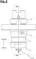
- Figures 1 and 2 show a FSW tool (10) with an upgrade kit (18) according to the present disclosure.
- the sectional view in Figure 1 is according to section line II in Figure 2 elected.
- the kit (18) comprises at least one adapter (12) and a shoulder cap (13).
- the adapter (12) is in a correspondingly adapted tool holder (15) on the FSW tool (10) can be used.
- a welding pin (11) can be inserted into the adapter (12).
- a (stepless) positioning (XA) of the adapter (12) and a (stepless) positioning (XP) of the welding pin (11) in the direction of a longitudinal axis (A) are provided.
- the welding pin (11), the adapter (12) and the tool holder (15) have a common longitudinal axis (A) about which the aforementioned components can be rotated together.
- the drive for the rotary movement can be generated in any way.
- the FSW tool (10) can preferably have its own rotary drive.
- the tool holder (15) can be permanently or detachably connected to an external drive, for example a spindle.
- the FSW tool (10) has a tool carrier (17) which can be designed as desired. Bearing points are preferably provided on the tool carrier (17) in order to receive the tool holder (15) rotatably about the longitudinal axis (A) and supported in the axial direction (A).
- the FSW tool (10) preferably also has a dome (16) which at least partially encloses an outside of the tool holder (15) and on which the shoulder cap (13) can be fixed in a rotationally fixed manner and supported in the axial direction (A).
- the FSW tool (17) is designed to receive the set-up (18) and to support or store it with respect to a common reference base.
- the FSW tool (10) is preferably designed as a manipulator-guided FSW tool that is used in an automated production process.
- the tool carrier (17) accordingly preferably has a flange element for connection to a manipulator hand and possibly to an output shaft of the manipulator.
- the manipulator can preferably be a five-, six- or seven-axis industrial robot.
- the manipulator hand can accordingly be a robot hand.
- the FSW tool with the kit (18), the dome (16), the tool holder (15) and the tool carrier (17) is preferably designed in such a way that the tool holder (15) with the adapter (12) is relative to the dome ( 16) is rotatably mounted and positioned on the tool carrier (17) in the direction of the longitudinal axis (A), and that the shoulder cap (13) is non-rotatably connected to the tool carrier (17) and is positioned in the direction of the longitudinal axis (A).
- the height of the adapter (12) in the direction of the longitudinal axis (A) and, on the other hand, the height of the welding pin (11) in the direction of the longitudinal axis (A) compared to the height of the welding shoulder area ( 13a) on the shoulder cap (13) can be adjusted to the desired size.
- the height of the shoulder cap (13) in the longitudinal direction (A) relative to the tool carrier (17) and / or the dome (16) can be adjusted, for example by inserting shims or other common construction variants.
- the shoulder cap (13) is an essentially rotationally symmetrical component which can be inserted into a correspondingly adapted receptacle at the distal end of the dome (16). Possibly.
- An anti-rotation device can be provided on the shoulder cap (13) and / or the dome (16), via which reaction forces from the welding process can be supported against the dome (16).
- the shoulder cap (13) is fixed to the dome (16) by a union nut (14).
- the union nut or another suitable fastening means for the shoulder cap (13) can also have a rotation lock.
- the shoulder cap (13) and the union nut (14) can be connected in one piece.
- the shoulder cap (13) can be fixed directly to the dome (16) by means of a thread or some other suitable construction means.
- shoulder cap (13) and union nut (14) have various advantages.
- the shoulder cap (13) is regularly repaired or replaced due to wear.
- the functional separation of the shoulder cap (13) and the union nut (14) enables a simpler and thus cheaper construction of the shoulder cap (13).
- the materials of the shoulder cap (13) and in particular the welding shoulder area (13a) on the one hand and the union nut (14) on the other hand, in particular the Fastening means (here thread) can be determined independently of each other. It is thus possible to provide shoulder caps (13) made of different materials for different welding requirements, each of which can be attached to the FSW tool (10) with the same or only a few variants of a union nut (14).
- FIG. 1 An enlarged view of the distal end of the FSW tool (10) is shown.
- the welding pin (11) and the adapter (12) are preferably set in a common rotary movement, in particular by driving the tool holder (15).
- the shoulder cap (13) with the welding shoulder area (13a) is not rotated with respect to the workpiece during the welding process, but only moved (together with the FSW tool) essentially along the intended welding path, which is usually a pure translational relative movement generated between the welding shoulder and the workpiece.
- a gap in particular an annular gap (21), is arranged between the distal end face (12b) and the welding shoulder area (13a) to allow the relative rotation between the welding pin (11) and the adapter (12) on the one hand and the shoulder cap (13) on the other to enable.
- the annular gap is delimited outward in the radial direction by an inner contour (20a) of the passage opening (20) on the shoulder cap (13).
- the annular gap (21) is delimited by a radial outer contour (12a) of the adapter (12).
- the annular gap (21) is preferably designed to be rotationally symmetrical to the longitudinal axis (A).
- the inner contour (20a) of the passage opening (20) and the radial outer contour (12a) of the adapter (12) are conically shaped at least at the distal end.
- the conical shape preferably extends over the entire length of the overlap between the inner contour (20a) and the outer contour (12a).
- the mean diameter of the annular gap (21) preferably increases in the dorsal direction along the longitudinal axis (A).
- the mean diameter of the annular gap (21) is smaller at the distal end than at the dorsal end.
- the clear width (D) (compare Figure 6 ) is therefore the same over the entire length of the annular gap (21) or increases in the dorsal direction.
- the mean diameter of the annular gap (21) can decrease in the dorsal direction along the longitudinal axis (A).
- the opening angle (W) of the conical inner contour (20a) has an amount between 10 ° and 45 ° (angular degrees). Furthermore, the opening angle (W) of the conical radial outer contour (12a) of the adapter (12) with respect to the longitudinal axis (A) is preferably between 10 ° and 45 ° (angular degrees). In other words, the opening angle (W) of the conical contour (20a) and the conical radial outer contour (12a) preferably have the same dimension. Alternatively, the opening angles can be slightly different.
- the opening angle of the inner contour (20a) is selected to be somewhat larger than the opening angle of the conical radial outer contour (12a), so that the clear width (D) of the annular gap (21) in the dorsal direction along the longitudinal axis (A) increases.
- the positioning (XA) can be done by any means and construction elements.
- One or more setting means for fixing the axial position of the adapter (12) and / or the welding pin (11) are preferably arranged on the tool holder (15). These setting means can in particular be designed as adjustable stops and / or as clamping devices. According to the examples in Figures 3 and 4 the setting means are designed as one or more clamping screws (not shown) which can be inserted into the tool holder (15) in the radial direction.
- FIGs 3 and 4 show preferred embodiments of a welding pin (11) and an adapter (12).
- the welding pin (11) and the adapter (12) can each have a shaft (25, 27) which is preferably rotationally symmetrical / cylindrical in shape.
- One or more flattened areas (26, 29) can be provided on this shaft (25, 27) which interact with the adjustment means mentioned above, in particular for producing a clamping connection.
- the aforementioned one or more clamping screws or other suitable locking means, which interact with the flattened areas (26, 29), can be arranged on the tool holder (15).
- the adapter (12) has a lateral opening (28) through which a clamping screw or other suitable adjustment means can reach in order to come into contact with the flat (16) on the welding pin (11).
- movable stops or adjusting screws arranged in the direction of the longitudinal axis (A) can be provided on the tool holder (15) and / or the adapter (12) to facilitate the positioning (XA) of the adapter (12) and / or to define the positioning (XP) of the welding pin (11) along the longitudinal axis (A).
- the conical radial outer contour (12a) of the adapter (12) and the conical inner contour (20a) of the shoulder cap (13) can be essentially smooth, ie they can form a regular conical surface (cf. Figures 5 and 6 ).
- first guide structure (22) can be arranged on the conical, radial outer contour (12a) of the adapter (12), which when the adapter (12) and the shoulder cap (13) rotates relative to one another in the annular gap (21 ) material located causes a conveying force in the direction of the longitudinal axis (A).
- a corresponding (first) guide structure can be arranged on the inner contour (20a) of the passage opening (20) (not shown) ).
- the (first) guide structure (22) can be designed in such a way that it brings about a conveying force in the direction of the outside of the FSW tool, ie in the distal direction.
- the conductive structure (22) causes material to be driven out during a welding process, which material possibly penetrates into the annular gap (21).
- a self-cleaning function is created for the annular gap (21), in which material is conveyed out of the gap again in the direction of the welding point.
- an intended direction of rotation for rotating the adapter (12) with respect to the shoulder cap (13) to produce a conveying force in the distal direction is indicated by a rotation arrow.
- the (first) guide structure (22) can be designed to bring about a conveying force in the direction of the inside of the FSW tool, ie in the dorsal direction.
- the annular gap (21) is self-cleaning, although the material is conveyed away to the inside. It is accordingly advantageous if a chamber (30) is arranged at the inner end of the annular gap (21) in the assembled state of the kit (cf. Fig. 6 ), which is designed to accommodate welding material passing through the annular gap (21).
- FIG 4 an embodiment variant is shown in which the aforementioned first guide structure (22) and additionally a second (inner / dorsal) guide structure (23) are arranged on the conical radial outer contour (12a) of the adapter (12).
- the second guide structure (23) is located closer to the inside of the FSW tool in the longitudinal direction (A), ie at the dorsal end of the conical radial outer contour (12a).
- the first and the second conductive structure (22, 23) are aligned opposite to one another.
- the first guide structure (22) can bring about a delivery force in the distal direction, ie towards the outside of the FSW tool, while the second guide contour (23) creates a delivery force in the dorsal direction, ie towards the inside of the FSW tool.
- the first guide structure thus serves to counteract the penetration of pasty material into the annular gap (21) or to convey material that has entered back to the welding point. If, however, too large an amount of material enters the annular gap while overcoming the first conveying force, the second guide structure causes emptying to the inside, in particular in the direction of the aforementioned chamber (30). Due to the size ratio between the first and the second guide contour (22, 23) and their characteristics, the conveying effects in the distal and dorsal direction can be adapted according to the process requirements.
- the aforementioned guide structures (22, 23) can have any design.
- a helical or thread-shaped recess in the conical radial outer contour (12a) for forming a guide structure (22, 23) is shown as an example.
- a different shape of a helix embedded or attached to the surface, attached blade surfaces or other suitable contours can be used.
- a cleaning effect for the annular gap (21) can alternatively or additionally be achieved by other measures.
- a pressure difference can be generated between the inner or dorsal opening and the outer or distal opening of the annular gap (21), which, as required, generates a conveying effect in the distal or dorsal direction on a material located in the annular gap (21).
- the FSW tool can do this be made pressure-tight with respect to the annular gap (21) and have a pressure source.
- the pressure source can preferably be controllable or regulatable.
- the shoulder cap (13) envelops the distal end region of the tool holder (15) in a pressure-tight manner. Furthermore, the shoulder cap (13) and the dome (16) can jointly enclose the tool holder (15) in a pressure-tight manner. In this way, a fluid passage or pressure line passage which can be pressurized is formed in the space between the shoulder cap (13) and the dome (16) on the one hand and the tool holder (15) and the adapter (12) on the other hand.
- the FSW tool (10) can preferably have a pressure source, in particular a positive pressure source, at the dorsal end.
- a conveying force directed outwards is exerted on a material located in the annular gap (21).
- the overpressure source can preferably be controlled or regulated in order to establish a balance between the reaction forces from the welding process, through which a material is conveyed into the annular gap (21), on the one hand, and the conveying forces used in the distal direction to clean the conveying gap on the other.
- the pressure source can be designed to generate a negative pressure.
- a conveying force can be exerted on any material located in the annular gap, which pulls the material inward, i.e. acts in the dorsal direction for cleaning.
- the generation of an overpressure can preferably be used during a welding operation in order to reduce or avoid the penetration of pasty material into the annular gap.
- the generation of a negative pressure can preferably be used after a welding operation in order to suck off any material present in the annular gap inwards. If necessary alternating overpressure and underpressure can be generated in order to generate a conveying force that changes in direction (inward / outward). A changing conveying force can be helpful in loosening material components that are already hardening.
- An operating method for an FSW tool with a pressure source for performing a welding operation preferably comprises the following steps: Feeding the FSW tool (10) to at least one workpiece, so that the welding pin (11) comes into contact with a workpiece surface. Execution of an immersion movement along the longitudinal axis (A) of the welding pin (11) until the auxiliary shoulder (12b) on the adapter (12) and / or the welding shoulder area (13a) of the shoulder cap (13) comes into contact with the workpiece surface . During and after the immersion movement, part of the material of the at least one workpiece is plasticized. The plasticization can be supported by the contact between the welding shoulder area (13a) and the workpiece and / or between the auxiliary shoulder (12b) and the workpiece.
- the pressure source of the FSW tool (10) is actuated in order to generate a pressure inside the FSW tool (10) and to exert a conveying force on a plasticized material that may be in the Annular gap (21) is located.
- the delivery force can be directed inwards (dorsal) or outwards (distal). Alternatively, the direction of the conveying force can change.
- the FSW tool (10) is preferably guided with an essentially translatory movement along a provided welding path.
- the plasticized material is preferably shaped by the auxiliary shoulder (12b) and / or the welding shoulder area (13a), in particular to form a desired seam shape or seam surface.
- the dome (16) can have one or more openings (24) arranged transversely to the longitudinal axis (A) through which the one or more setting means for determining the axial position (XA, XP) of the adapter (12) and / or the welding pin ( 12) are accessible.
- corresponding closure caps can be provided for these openings (24).
- FIG Figures 5 and 6 a preferred method for adapting the FSW tool (10) or an upgrade kit (18) for a welding operation or a welding process is explained.
- the adapter (12) can according to the Figures 5 and 6 in the embodiment shown on the left have a distal excess length so that in the basic state it protrudes beyond the height of the welding shoulder area (13a) in the distal direction along the longitudinal axis (A). If the adapter (12) is moved along the longitudinal axis (A) maximally in the distal direction until the conical radial outer contour (12a) comes to rest on the inner contour (20a) of the passage opening (20), the end face (12b) of the Adapters (12) protrude in the distal direction beyond the welding shoulder area (13a) of the shoulder cap (13). In this position, the clear width (D) of the annular gap (21) is reduced to a minimum, in particular equal to zero.
- the position (XA) of the adapter (12) can be set in the longitudinal direction (A) relative to the position of the shoulder cap (13) or relative to this starting position such that the width (D) of the annular gap (21) is set to a desired Dimension is determined, in particular in that the adapter (12) is displaced relative to the aforementioned starting position in the dorsal direction along the longitudinal axis (A).
- the adapter (12) can be adjusted relative to the shoulder cap (13) in the Set longitudinal direction (A), in particular clamped and / or supported on a stop.
- the overhang of the adapter (12) can then be shortened at the distal end.
- a shortening (12c) of the adapter (12) is shown by such an amount that the height of the end face (12b) of the adapter (12) in the direction of the longitudinal axis (A) is adapted to the height of the welding shoulder area (13a) .
- the adapter (12) is shortened in order to set a height difference between the end face (12b) and the welding shoulder area (13a) to a desired level.
- the shoulder cap (13) can be shortened at least in the area of the welding shoulder area (13a) in order to set a height difference between the end face (12b) and the welding shoulder area (13a) to a desired level. Accordingly, an adapter (12) can be provided without the above-mentioned protrusion.
- the end face (12b) of the adapter (12) can in particular take place in such a way that a uniform height of the welding shoulder area (13a) and the end face (12b) of the adapter (12) is produced in the direction of the longitudinal axis (A).
- a shortening can take place in such a way that the surface dimensions of the welding shoulder area (13a) and / or the end face (12b) can be adjusted to a desired dimension or a desired area ratio.
- the shortening of the adapter (12) and / or the shoulder cap (13) can be achieved in any way, in particular by a machining process such as milling, turning or grinding. Possibly. a filler material can be introduced into the annular gap (21) for the period of the shortening in order to prevent chips or other undesired foreign particles from penetrating into the annular gap (21) during the shortening.
- the shoulder cap (13) can have one or more openings or recesses through which, for example, material conveyed to the inside of the FSW tool (10) can escape to the outside again.
- the shoulder cap (13) can in particular be bow-shaped or perforated disk-shaped.
- the welding pin (11) can have any design. In particular, it can be a standardized tool.
- a conversion kit (18) for an FSW tool (10) can, in addition to the shoulder cap (13) and the adapter (12), one or more welding pins (11) and, if necessary, one or more tool holders (15) and setting means for determining the position the adapter (12) and / or the welding pin (11).
- the dome (16) can be connected in one piece to the tool carrier (17).
- the distal end face (12a) of the adapter (12) can serve as an auxiliary shoulder. It is usually moved at the same speed of rotation as the welding pin (11).
- the size (area) of the auxiliary shoulder can be set to the desired size by shortening the adapter (12) or its protrusion, regardless of the setting of the width (D) of the annular gap (21) and the depth of penetration of the welding pin (11) .
Landscapes
- Engineering & Computer Science (AREA)
- Mechanical Engineering (AREA)
- Physics & Mathematics (AREA)
- Optics & Photonics (AREA)
- Pressure Welding/Diffusion-Bonding (AREA)
- Lining Or Joining Of Plastics Or The Like (AREA)
- Resistance Welding (AREA)
Claims (15)
- Kit pour un outil FSW (soudage friction-malaxage) (10) comprenant un adaptateur (12) pouvant être inséré dans un porte-outil (15) et conçu pour recevoir une broche de soudage (11), et un capuchon à épaulement (13) avec une ouverture de passage (20) pour la broche de soudage (11) et l'adaptateur (12), le capuchon à épaulement (13) présentant une zone d'épaulement de soudage (21) se raccordant à l'ouverture de passage (20) sur la surface extérieure, et dans lequel l'adaptateur (12) peut tourner par rapport à la calotte d'épaule autour d'un axe longitudinal (A) s'étendant concentriquement à l'ouverture de passage (20), caractérisé en ce que le contour intérieur (20a) de l'ouverture de passage (20) et un contour extérieur radial (12a) de l'adaptateur (12) sont de forme conique au moins à l'extrémité tournée vers le point de soudure.
- Kit selon la revendication 1, dans lequel l'adaptateur (12) et le porte-outil (15) sont conçus de telle manière qu'un positionnement de l'adaptateur dans la direction de l'axe longitudinal (A) par rapport à la zone d'épaulement de soudage (13a) est réglable en continu.
- Kit selon la revendication 1 ou 2, dans lequel l'adaptateur (12) est conçu de telle manière qu'un positionnement de la broche de soudage (11) le long de l'axe longitudinal (A) est réglable en continu.
- Kit selon l'une des revendications précédentes, dans lequel un espace annulaire (21) est formé entre le capuchon d'épaulement (13) et l'adaptateur (12) au moins dans la région de l'ouverture de passage (21), dans lequel une (première) structure de guidage (22) est disposée sur le contour extérieur radial conique (12a) de l'adaptateur (12) et/ou sur le contour intérieur (20a) de l'ouverture de passage (20), qui, lors de la rotation relative entre l'adaptateur (12) et le chapeau d'épaulement (13), produit une force de transport dans la direction de l'axe longitudinal (A) sur un matériau se trouvant dans l'interstice annulaire (21).
- Kit selon la revendication 4, dans lequel une deuxième structure de guidage (intérieure) (23) est en outre disposée sur le contour extérieur radial conique (12a) de l'adaptateur (12) et/ou sur le contour intérieur (20a) de l'ouverture de passage (20), laquelle deuxième structure de guidage (intérieure) (23) est située plus près de l'intérieur de l'outil FSW dans la direction longitudinale (A), et dans lequel la première structure de guidage (extérieure) (22) provoque une force de transport en direction de l'extérieur de l'outil de soudage par compression et la seconde structure de guidage (intérieure) (23) provoque une force de transport en direction de l'intérieur de l'outil de soudage par compression.
- Kit selon l'une des revendications précédentes, dans lequel, à l'état monté de l'ensemble de montage, une chambre (30) est disposée à l'extrémité intérieure de l'interstice annulaire (21), laquelle chambre sert à recevoir le matériau de soudage passant à travers l'interstice annulaire (21).
- Kit selon l'une des revendications précédentes, dans lequel un ou plusieurs moyens de réglage pour fixer la position axiale (XA, XP) de l'adaptateur (12) et/ou du goujon soudé (11) sont disposés sur le porte-outil (15) et/ou sur l'adaptateur (12), en particulier sous la forme de butées réglables, de dispositifs de serrage ou de vis de serrage.
- Outil FSW (soudage friction-malaxage) comprenant un kit de montage (18) selon la revendication 1, un dôme (16) qui entoure le porte-outil (15) et un support d'outil (17) sur lequel le porte-outil (15) et/ou le dôme (16) sont montés, caractérisé en ce que le porte-outil (15) est monté à rotation par rapport au dôme (16) et est supporté sur le support d'outil (17) dans la direction de l'axe longitudinal (A), et en ce que le capuchon d'épaulement (13) est relié au support d'outil (17) de manière solidaire en rotation et est supporté dans la direction de l'axe longitudinal.
- Outil FSW selon la revendication précédente, dans lequel le porte-outil (17) est adapté pour être fixé à un manipulateur, en particulier à un robot industriel multi-axes.
- Outil FSW selon l'une des revendications précédentes, dans lequel le capuchon d'épaulement (13) est relié au dôme (16) par un moyen de fixation séparé, en particulier par un écrou-raccord (14), et dans lequel le dôme (16) présente une ou plusieurs ouvertures (24) disposées transversalement à l'axe longitudinal (A), par lesquelles un ou plusieurs moyens de réglage pour fixer la position axiale de l'adaptateur (12) et/ou du goujon soudé (11) sont accessibles.
- Outil FSW selon l'une des revendications précédentes, dans lequel l'épaulement (13) et le dôme (16) entourent le logement d'outil (15) de manière étanche à la pression, et dans lequel l'outil FSW (10) comporte une source de pression de sorte que lorsqu'une pression est générée à l'intérieur de l'outil FSW (10), une force de transport dirigée vers l'extérieur ou vers l'intérieur est exercée sur un matériau situé dans l'espace annulaire (21) .
- Procédé d'adaptation d'un kit (18) ou d'un outil FSW (10) selon l'une des exigences précédentes pour une opération de soudage, caractérisé par l'étape suivante:- déterminer la position (XA) de l'adaptateur (12) dans le sens longitudinal (A) par rapport à la position de la calotte d'épaule (13) de telle sorte que la largeur (D) de l'espace annulaire (21) soit réglée à une dimension souhaitée.
- Procédé selon la revendication précédente, comprenant en outre les étapes:- Raccourcir (12c) au moins l'adaptateur (12) dans la zone de la face avant (12b) ou au moins l'épaulement (13) dans la zone de l'épaulement de soudage (13a) afin d'ajuster une différence de hauteur entre la face avant (12b) et l'épaulement de soudage (13a) à une dimension souhaitée, en particulier pour réduire ou éliminer une telle différence de hauteur.
- Procédé selon l'une des revendications précédentes, dans lequel la face frontale de l'adaptateur (12) est raccourcie dans la direction de l'axe longitudinal (A) avec une zone d'épaulement de soudage (13a),- de sorte qu'une hauteur uniforme de la zone d'épaulement de soudage (13a) et de la face frontale (12b) de l'adaptateur (12) soit produite dans la direction de l'axe longitudinal (A), et/ou- afin que les dimensions de la surface de l'épaulement de soudage (13a) et/ou de la face frontale (12b) soient ajustées à une dimension souhaitée.
- Procédé de fonctionnement d'un outil FSW selon la revendication 11, pour effectuer au moins une opération de soudage comprenant les étapes suivantes:- Avance de l'outil FSW (10) sur au moins une pièce de manière à ce que la goupille de soudage (11) entre en contact avec la surface d'une pièce;- Exécution d'un mouvement d'immersion le long de l'axe longitudinal (A) du goujon de soudage (11) jusqu'à ce qu'un épaulement auxiliaire (12b) sur l'adaptateur (12) et/ou une partie d'épaulement de soudage (13a) du capuchon d'épaulement (13) entre en contact avec la surface de la pièce, une partie du matériau d'au moins une pièce étant ainsi plastifiée;- Pendant au moins une opération de soudage et/ou après une opération de soudage:
actionnement de la source de pression de l'outil FSW (10) afin de générer une pression dans l'outil FSW (10) et d'exercer une force de transport sur un matériau plastifié éventuellement situé dans l'espace annulaire (21).
Applications Claiming Priority (2)
| Application Number | Priority Date | Filing Date | Title |
|---|---|---|---|
| DE102016113289.6A DE102016113289A1 (de) | 2016-07-19 | 2016-07-19 | FSW-Werkzeug mit fester Schulter |
| PCT/EP2017/068222 WO2018015429A1 (fr) | 2016-07-19 | 2017-07-19 | Outil de soudage par friction-malaxage muni d'un épaulement fixe |
Publications (2)
| Publication Number | Publication Date |
|---|---|
| EP3487655A1 EP3487655A1 (fr) | 2019-05-29 |
| EP3487655B1 true EP3487655B1 (fr) | 2020-10-07 |
Family
ID=59381282
Family Applications (1)
| Application Number | Title | Priority Date | Filing Date |
|---|---|---|---|
| EP17742228.4A Active EP3487655B1 (fr) | 2016-07-19 | 2017-07-19 | Outil fsw avec épaulière fixe |
Country Status (6)
| Country | Link |
|---|---|
| US (1) | US10953489B2 (fr) |
| EP (1) | EP3487655B1 (fr) |
| KR (1) | KR102336483B1 (fr) |
| CN (1) | CN109475972B (fr) |
| DE (1) | DE102016113289A1 (fr) |
| WO (1) | WO2018015429A1 (fr) |
Families Citing this family (23)
| Publication number | Priority date | Publication date | Assignee | Title |
|---|---|---|---|---|
| GB201618422D0 (en) * | 2016-11-01 | 2016-12-14 | Welding Inst The | Method and apparatus for creating channels in workpieces |
| JP6770014B2 (ja) * | 2018-03-19 | 2020-10-14 | Primetals Technologies Japan株式会社 | 摩擦攪拌接合装置用アイロニングプレートとそれを備えた摩擦攪拌接合装置、ならびに摩擦攪拌接合方法 |
| US10456858B2 (en) * | 2018-03-30 | 2019-10-29 | Esab Ab | Welding head for friction stir welding |
| DE102018113680A1 (de) * | 2018-06-08 | 2019-12-12 | Kuka Deutschland Gmbh | Kopfstück, Schweißwerkzeug und Schweißverfahren |
| CN109014559B (zh) * | 2018-08-09 | 2020-07-28 | 湖南文理学院 | 一种静止轴肩式机器人系数检测方法 |
| KR102120389B1 (ko) * | 2018-10-24 | 2020-06-08 | 주식회사윈젠 | 숄더부가 구비된 마찰교반 용접장치 |
| DE102019006413A1 (de) | 2019-09-11 | 2021-03-11 | Grenzebach Maschinenbau Gmbh | Vorrichtung und Verfahren zur Erhöhung der Schnelligkeit und der Erhöhung der Standfestigkeit des Schweißpins beim Rührreibschweißen. |
| CN111922505B (zh) * | 2020-07-27 | 2022-01-18 | 昆山哈工万洲焊接研究院有限公司 | 一种搅拌摩擦焊焊具及装置 |
| US12415229B2 (en) | 2020-07-29 | 2025-09-16 | Blue Origin Manufacturing, LLC | Friction stir welding systems and methods |
| CN112207415B (zh) * | 2020-09-14 | 2022-04-15 | 湖南坤鼎数控科技有限公司 | 一种便于固定摩擦焊头的摩擦焊装置 |
| CN113020880B (zh) * | 2021-04-14 | 2023-06-20 | 深圳市新晨阳电子有限公司 | 一种集成电路板研发用贴片电阻焊接试制工装 |
| NL2028068B1 (en) * | 2021-04-26 | 2022-11-03 | Univ Twente | Apparatus for friction stir applications and method for manufacturing such an apparatus |
| FR3132450A1 (fr) * | 2022-02-10 | 2023-08-11 | Stirweld | Accessoire d’interface de travail, kit de travail et procédé de soudage par friction-malaxage |
| JP2023152110A (ja) * | 2022-04-01 | 2023-10-16 | 川崎重工業株式会社 | 摩擦撹拌接合装置及びそのメンテナンス方法 |
| KR102846246B1 (ko) | 2022-12-29 | 2025-08-13 | 조선대학교산학협력단 | 냉각장치 및 이를 포함하는 마찰교반용접 툴 |
| US12151301B2 (en) * | 2023-03-24 | 2024-11-26 | National Chung Cheng University | Friction stir welding tool holder with thermal sensor |
| US12246392B2 (en) | 2023-03-30 | 2025-03-11 | Blue Origin Manufacturing, LLC | Deposition head for friction stir additive manufacturing devices and methods |
| US12140109B2 (en) | 2023-03-30 | 2024-11-12 | Blue Origin, Llc | Transpiration-cooled systems having permeable and non-permeable portions |
| US12172229B2 (en) | 2023-03-30 | 2024-12-24 | Blue Origin, Llc | Friction stir additive manufacturing devices and methods for forming in-situ rivets |
| US20240399493A1 (en) * | 2023-06-05 | 2024-12-05 | Ut-Battelle, Llc | Friction pressure welding of similar and/or dissimilar materials |
| US12303994B2 (en) | 2023-08-03 | 2025-05-20 | Blue Origin Manufacturing, LLC | Friction stir additive manufacturing formed parts and structures with integrated passages |
| US12383975B2 (en) | 2023-08-03 | 2025-08-12 | Blue Origin Manufacturing, LLC | Friction stir additive manufacturing formed parts and structures with integrated passages |
| US20250187104A1 (en) | 2023-12-12 | 2025-06-12 | Blue Origin, Llc | Nosecones for friction stir additive manufacturing systems, devices, and methods |
Family Cites Families (20)
| Publication number | Priority date | Publication date | Assignee | Title |
|---|---|---|---|---|
| GB9125978D0 (en) * | 1991-12-06 | 1992-02-05 | Welding Inst | Hot shear butt welding |
| JP3081799B2 (ja) * | 1996-11-01 | 2000-08-28 | 昭和アルミニウム株式会社 | アルミニウム材の接合方法 |
| US7448526B2 (en) * | 2004-08-10 | 2008-11-11 | Transformation Technologies, Inc. | Adapter for friction stir welding |
| US7748591B2 (en) | 2004-12-14 | 2010-07-06 | The Boeing Company | Pressure foot clamp for friction stir welding machine |
| JP4754256B2 (ja) * | 2005-04-19 | 2011-08-24 | 住友軽金属工業株式会社 | 摩擦撹拌点接合用回転工具及びそれを用いた摩擦撹拌点接合方法 |
| US7581665B2 (en) * | 2006-01-04 | 2009-09-01 | The Boeing Company | Methods and apparatus for retractable pin friction stir welding and spot welding |
| US20070228104A1 (en) * | 2006-03-31 | 2007-10-04 | Mankus Gary R | Friction stir welding spindle assembly |
| WO2008082420A1 (fr) * | 2007-01-05 | 2008-07-10 | The Boeing Company | Procédés et appareil destinés à un soudage par friction malaxage à pion rétractable et à un soudage par points |
| JP5149607B2 (ja) * | 2007-12-13 | 2013-02-20 | 株式会社日立製作所 | 摩擦攪拌装置及び摩擦攪拌プロセス |
| US8052028B2 (en) | 2008-06-16 | 2011-11-08 | GM Global Technology Operations LLC | Device for use with a friction stir spot welding (FSSW) apparatus |
| JP5304583B2 (ja) * | 2009-10-09 | 2013-10-02 | 日本軽金属株式会社 | 内隅接合用回転ツール及びこれを用いた内隅接合方法 |
| US8708628B2 (en) * | 2010-11-23 | 2014-04-29 | Centre De Recherche Industrielle Du Quebec | Insertion component and method for inserting thereof through the surface of a workpiece |
| EP3406395A3 (fr) * | 2010-11-23 | 2019-04-03 | Centre De Recherche Industrielle Du Quebec | Element de fixation par insertion et son procédé d'insertion au travers de la surface d'une pièce |
| US8708214B2 (en) | 2011-04-22 | 2014-04-29 | GM Global Technology Operations LLC | Servo-controlled rotating clamping device for use with a friction stir spot welding apparatus |
| DE102011106506A1 (de) * | 2011-06-15 | 2012-12-20 | Eurocopter Deutschland Gmbh | Schweißwerkzeug zum Verbinden von wenigstens zwei Werkstücken, Schweißverfahren und Werkstück |
| CN102581476B (zh) * | 2012-03-28 | 2014-10-01 | 首都航天机械公司 | 修补运载火箭贮箱搅拌摩擦焊焊缝缺陷的装置及方法 |
| DE102012010836B3 (de) | 2012-05-31 | 2013-06-20 | Grenzebach Maschinenbau Gmbh | Verfahren und Vorrichtung zur Verbesserung der Qualität der Schweißnaht beim Rührreibschweißen, Computerprogramm sowie maschinenlesbarer Träger |
| DE102014001050A1 (de) * | 2014-01-28 | 2015-07-30 | Grenzebach Maschinenbau Gmbh | Verfahren und Vorrichtung zum Rührreibschweißen bei Materialien unterschiedlicher Dicke und bei Kehlnähten |
| DE102014004331B3 (de) | 2014-03-26 | 2015-06-11 | Grenzebach Maschinenbau Gmbh | Verfahren und Vorrichtung zur Erhöhung der Qualität der Schweißnaht beim Rührreibschweißen sowie Computerprogramm und maschinenlesbarer Träger mit einem Programmcode zur Durchführung des Verfahrens |
| CN105108316A (zh) * | 2015-09-15 | 2015-12-02 | 昆山斯格威电子科技有限公司 | 一种搅拌摩擦点焊设备去除积屑的装置 |
-
2016
- 2016-07-19 DE DE102016113289.6A patent/DE102016113289A1/de not_active Ceased
-
2017
- 2017-07-19 EP EP17742228.4A patent/EP3487655B1/fr active Active
- 2017-07-19 KR KR1020197001534A patent/KR102336483B1/ko active Active
- 2017-07-19 US US16/319,204 patent/US10953489B2/en active Active
- 2017-07-19 WO PCT/EP2017/068222 patent/WO2018015429A1/fr not_active Ceased
- 2017-07-19 CN CN201780045048.6A patent/CN109475972B/zh active Active
Non-Patent Citations (1)
| Title |
|---|
| None * |
Also Published As
| Publication number | Publication date |
|---|---|
| DE102016113289A1 (de) | 2018-01-25 |
| KR102336483B1 (ko) | 2021-12-07 |
| CN109475972A (zh) | 2019-03-15 |
| CN109475972B (zh) | 2022-02-22 |
| US10953489B2 (en) | 2021-03-23 |
| WO2018015429A1 (fr) | 2018-01-25 |
| KR20190032363A (ko) | 2019-03-27 |
| EP3487655A1 (fr) | 2019-05-29 |
| US20190262935A1 (en) | 2019-08-29 |
Similar Documents
| Publication | Publication Date | Title |
|---|---|---|
| EP3487655B1 (fr) | Outil fsw avec épaulière fixe | |
| DE60102963T2 (de) | Drehendes Reibungschweissen | |
| EP2596898B1 (fr) | Outil de soudage par friction autobloquant | |
| EP2810735B1 (fr) | Outil et procédé de soudage par friction malaxage avec un épaulement non circonférentiel | |
| DE102011015831B3 (de) | Vorrichtung zum Reibrührschweißen | |
| EP1750879B1 (fr) | Procede et dispositif pour usiner, par enlevement de matiere, des surfaces a symetrie de revolution d'une piece | |
| DE102016105927A1 (de) | Rührreibschweißtechnologie zum Verbinden von Bauteilen aus unterschiedlichen Materialien | |
| EP2813314B1 (fr) | Outil et procédé de friction-malaxage pour une pièce comprenant un revêtement | |
| DE102008056682B4 (de) | Fräs- und Entgratwerkzeug | |
| DE29724590U1 (de) | Fräseinrichtung | |
| EP4100186B1 (fr) | Outil de laminage et procédé de laminage d'un profilé | |
| EP2087963B1 (fr) | Procédé de soudage par friction | |
| DE3517246C2 (fr) | ||
| EP2976174B1 (fr) | Élément d'alésage et alésoir et sa méthode de production | |
| EP3170601B1 (fr) | Dispositif de moulage ou de taraudage de filets et procédé de fabrication d'un dispositif de moulage ou de taraudage de filets | |
| DE102019200829B4 (de) | Rotations-Werkzeug zur Erzeugung eines Honfreigangs | |
| DE10344481B4 (de) | Vorrichtung zum mechanischen Entfernen von Ablagerungen, insbesondere von Ablagerungen an Schweißelektroden für das Widerstandsschweißen | |
| DE202016105555U1 (de) | Rührreibschweißtechnologie zum Verbinden von Bauteilen aus unterschiedlichen Materialien | |
| DE102006011300B3 (de) | Drehmaschine und Verfahren zur Herstellung rotationssymmetrischer Flächen eines Werkstückes und Verwendung einer Drehmaschine | |
| DE102004019302B4 (de) | Räumwerkzeug und Verfahren zur spanenden Bearbeitung von Bohrungsoberflächen | |
| EP4135929B1 (fr) | Dispositif et procédé pour raccorder une buse de refroidissement à une alimentation en lubrifiant de refroidissement | |
| EP2705916B1 (fr) | Outil de perçage et utilisation d'un outil de perçage | |
| EP1877214B1 (fr) | Procede de tournage | |
| DE102018112193B4 (de) | Verfahren zur Herstellung einer Nietverbindung | |
| DE102017100376B4 (de) | Zerspanungswerkzeug und Verfahren zum Entgraten von Kanten in Hohlräumen |
Legal Events
| Date | Code | Title | Description |
|---|---|---|---|
| STAA | Information on the status of an ep patent application or granted ep patent |
Free format text: STATUS: UNKNOWN |
|
| STAA | Information on the status of an ep patent application or granted ep patent |
Free format text: STATUS: THE INTERNATIONAL PUBLICATION HAS BEEN MADE |
|
| PUAI | Public reference made under article 153(3) epc to a published international application that has entered the european phase |
Free format text: ORIGINAL CODE: 0009012 |
|
| STAA | Information on the status of an ep patent application or granted ep patent |
Free format text: STATUS: REQUEST FOR EXAMINATION WAS MADE |
|
| 17P | Request for examination filed |
Effective date: 20190116 |
|
| AK | Designated contracting states |
Kind code of ref document: A1 Designated state(s): AL AT BE BG CH CY CZ DE DK EE ES FI FR GB GR HR HU IE IS IT LI LT LU LV MC MK MT NL NO PL PT RO RS SE SI SK SM TR |
|
| AX | Request for extension of the european patent |
Extension state: BA ME |
|
| DAV | Request for validation of the european patent (deleted) | ||
| DAX | Request for extension of the european patent (deleted) | ||
| GRAP | Despatch of communication of intention to grant a patent |
Free format text: ORIGINAL CODE: EPIDOSNIGR1 |
|
| STAA | Information on the status of an ep patent application or granted ep patent |
Free format text: STATUS: GRANT OF PATENT IS INTENDED |
|
| INTG | Intention to grant announced |
Effective date: 20200325 |
|
| GRAJ | Information related to disapproval of communication of intention to grant by the applicant or resumption of examination proceedings by the epo deleted |
Free format text: ORIGINAL CODE: EPIDOSDIGR1 |
|
| STAA | Information on the status of an ep patent application or granted ep patent |
Free format text: STATUS: REQUEST FOR EXAMINATION WAS MADE |
|
| GRAS | Grant fee paid |
Free format text: ORIGINAL CODE: EPIDOSNIGR3 |
|
| STAA | Information on the status of an ep patent application or granted ep patent |
Free format text: STATUS: GRANT OF PATENT IS INTENDED |
|
| INTC | Intention to grant announced (deleted) | ||
| GRAP | Despatch of communication of intention to grant a patent |
Free format text: ORIGINAL CODE: EPIDOSNIGR1 |
|
| GRAA | (expected) grant |
Free format text: ORIGINAL CODE: 0009210 |
|
| STAA | Information on the status of an ep patent application or granted ep patent |
Free format text: STATUS: THE PATENT HAS BEEN GRANTED |
|
| INTG | Intention to grant announced |
Effective date: 20200811 |
|
| AK | Designated contracting states |
Kind code of ref document: B1 Designated state(s): AL AT BE BG CH CY CZ DE DK EE ES FI FR GB GR HR HU IE IS IT LI LT LU LV MC MK MT NL NO PL PT RO RS SE SI SK SM TR |
|
| REG | Reference to a national code |
Ref country code: GB Ref legal event code: FG4D Free format text: NOT ENGLISH |
|
| REG | Reference to a national code |
Ref country code: CH Ref legal event code: EP Ref country code: AT Ref legal event code: REF Ref document number: 1320617 Country of ref document: AT Kind code of ref document: T Effective date: 20201015 |
|
| REG | Reference to a national code |
Ref country code: IE Ref legal event code: FG4D Free format text: LANGUAGE OF EP DOCUMENT: GERMAN |
|
| REG | Reference to a national code |
Ref country code: DE Ref legal event code: R096 Ref document number: 502017007629 Country of ref document: DE |
|
| REG | Reference to a national code |
Ref country code: SE Ref legal event code: TRGR |
|
| REG | Reference to a national code |
Ref country code: NL Ref legal event code: MP Effective date: 20201007 |
|
| PG25 | Lapsed in a contracting state [announced via postgrant information from national office to epo] |
Ref country code: GR Free format text: LAPSE BECAUSE OF FAILURE TO SUBMIT A TRANSLATION OF THE DESCRIPTION OR TO PAY THE FEE WITHIN THE PRESCRIBED TIME-LIMIT Effective date: 20210108 Ref country code: FI Free format text: LAPSE BECAUSE OF FAILURE TO SUBMIT A TRANSLATION OF THE DESCRIPTION OR TO PAY THE FEE WITHIN THE PRESCRIBED TIME-LIMIT Effective date: 20201007 Ref country code: NO Free format text: LAPSE BECAUSE OF FAILURE TO SUBMIT A TRANSLATION OF THE DESCRIPTION OR TO PAY THE FEE WITHIN THE PRESCRIBED TIME-LIMIT Effective date: 20210107 Ref country code: RS Free format text: LAPSE BECAUSE OF FAILURE TO SUBMIT A TRANSLATION OF THE DESCRIPTION OR TO PAY THE FEE WITHIN THE PRESCRIBED TIME-LIMIT Effective date: 20201007 Ref country code: PT Free format text: LAPSE BECAUSE OF FAILURE TO SUBMIT A TRANSLATION OF THE DESCRIPTION OR TO PAY THE FEE WITHIN THE PRESCRIBED TIME-LIMIT Effective date: 20210208 |
|
| REG | Reference to a national code |
Ref country code: LT Ref legal event code: MG4D |
|
| PG25 | Lapsed in a contracting state [announced via postgrant information from national office to epo] |
Ref country code: BG Free format text: LAPSE BECAUSE OF FAILURE TO SUBMIT A TRANSLATION OF THE DESCRIPTION OR TO PAY THE FEE WITHIN THE PRESCRIBED TIME-LIMIT Effective date: 20210107 Ref country code: IS Free format text: LAPSE BECAUSE OF FAILURE TO SUBMIT A TRANSLATION OF THE DESCRIPTION OR TO PAY THE FEE WITHIN THE PRESCRIBED TIME-LIMIT Effective date: 20210207 Ref country code: LV Free format text: LAPSE BECAUSE OF FAILURE TO SUBMIT A TRANSLATION OF THE DESCRIPTION OR TO PAY THE FEE WITHIN THE PRESCRIBED TIME-LIMIT Effective date: 20201007 Ref country code: PL Free format text: LAPSE BECAUSE OF FAILURE TO SUBMIT A TRANSLATION OF THE DESCRIPTION OR TO PAY THE FEE WITHIN THE PRESCRIBED TIME-LIMIT Effective date: 20201007 Ref country code: ES Free format text: LAPSE BECAUSE OF FAILURE TO SUBMIT A TRANSLATION OF THE DESCRIPTION OR TO PAY THE FEE WITHIN THE PRESCRIBED TIME-LIMIT Effective date: 20201007 |
|
| PG25 | Lapsed in a contracting state [announced via postgrant information from national office to epo] |
Ref country code: HR Free format text: LAPSE BECAUSE OF FAILURE TO SUBMIT A TRANSLATION OF THE DESCRIPTION OR TO PAY THE FEE WITHIN THE PRESCRIBED TIME-LIMIT Effective date: 20201007 Ref country code: NL Free format text: LAPSE BECAUSE OF FAILURE TO SUBMIT A TRANSLATION OF THE DESCRIPTION OR TO PAY THE FEE WITHIN THE PRESCRIBED TIME-LIMIT Effective date: 20201007 |
|
| REG | Reference to a national code |
Ref country code: DE Ref legal event code: R097 Ref document number: 502017007629 Country of ref document: DE |
|
| PG25 | Lapsed in a contracting state [announced via postgrant information from national office to epo] |
Ref country code: SM Free format text: LAPSE BECAUSE OF FAILURE TO SUBMIT A TRANSLATION OF THE DESCRIPTION OR TO PAY THE FEE WITHIN THE PRESCRIBED TIME-LIMIT Effective date: 20201007 Ref country code: EE Free format text: LAPSE BECAUSE OF FAILURE TO SUBMIT A TRANSLATION OF THE DESCRIPTION OR TO PAY THE FEE WITHIN THE PRESCRIBED TIME-LIMIT Effective date: 20201007 Ref country code: CZ Free format text: LAPSE BECAUSE OF FAILURE TO SUBMIT A TRANSLATION OF THE DESCRIPTION OR TO PAY THE FEE WITHIN THE PRESCRIBED TIME-LIMIT Effective date: 20201007 Ref country code: LT Free format text: LAPSE BECAUSE OF FAILURE TO SUBMIT A TRANSLATION OF THE DESCRIPTION OR TO PAY THE FEE WITHIN THE PRESCRIBED TIME-LIMIT Effective date: 20201007 Ref country code: SK Free format text: LAPSE BECAUSE OF FAILURE TO SUBMIT A TRANSLATION OF THE DESCRIPTION OR TO PAY THE FEE WITHIN THE PRESCRIBED TIME-LIMIT Effective date: 20201007 Ref country code: RO Free format text: LAPSE BECAUSE OF FAILURE TO SUBMIT A TRANSLATION OF THE DESCRIPTION OR TO PAY THE FEE WITHIN THE PRESCRIBED TIME-LIMIT Effective date: 20201007 |
|
| PLBE | No opposition filed within time limit |
Free format text: ORIGINAL CODE: 0009261 |
|
| STAA | Information on the status of an ep patent application or granted ep patent |
Free format text: STATUS: NO OPPOSITION FILED WITHIN TIME LIMIT |
|
| PG25 | Lapsed in a contracting state [announced via postgrant information from national office to epo] |
Ref country code: DK Free format text: LAPSE BECAUSE OF FAILURE TO SUBMIT A TRANSLATION OF THE DESCRIPTION OR TO PAY THE FEE WITHIN THE PRESCRIBED TIME-LIMIT Effective date: 20201007 |
|
| 26N | No opposition filed |
Effective date: 20210708 |
|
| PG25 | Lapsed in a contracting state [announced via postgrant information from national office to epo] |
Ref country code: AL Free format text: LAPSE BECAUSE OF FAILURE TO SUBMIT A TRANSLATION OF THE DESCRIPTION OR TO PAY THE FEE WITHIN THE PRESCRIBED TIME-LIMIT Effective date: 20201007 Ref country code: IT Free format text: LAPSE BECAUSE OF FAILURE TO SUBMIT A TRANSLATION OF THE DESCRIPTION OR TO PAY THE FEE WITHIN THE PRESCRIBED TIME-LIMIT Effective date: 20201007 |
|
| PG25 | Lapsed in a contracting state [announced via postgrant information from national office to epo] |
Ref country code: SI Free format text: LAPSE BECAUSE OF FAILURE TO SUBMIT A TRANSLATION OF THE DESCRIPTION OR TO PAY THE FEE WITHIN THE PRESCRIBED TIME-LIMIT Effective date: 20201007 |
|
| REG | Reference to a national code |
Ref country code: CH Ref legal event code: PL |
|
| PG25 | Lapsed in a contracting state [announced via postgrant information from national office to epo] |
Ref country code: MC Free format text: LAPSE BECAUSE OF FAILURE TO SUBMIT A TRANSLATION OF THE DESCRIPTION OR TO PAY THE FEE WITHIN THE PRESCRIBED TIME-LIMIT Effective date: 20201007 |
|
| REG | Reference to a national code |
Ref country code: BE Ref legal event code: MM Effective date: 20210731 |
|
| PG25 | Lapsed in a contracting state [announced via postgrant information from national office to epo] |
Ref country code: LI Free format text: LAPSE BECAUSE OF NON-PAYMENT OF DUE FEES Effective date: 20210731 Ref country code: CH Free format text: LAPSE BECAUSE OF NON-PAYMENT OF DUE FEES Effective date: 20210731 |
|
| PG25 | Lapsed in a contracting state [announced via postgrant information from national office to epo] |
Ref country code: IS Free format text: LAPSE BECAUSE OF FAILURE TO SUBMIT A TRANSLATION OF THE DESCRIPTION OR TO PAY THE FEE WITHIN THE PRESCRIBED TIME-LIMIT Effective date: 20210207 Ref country code: LU Free format text: LAPSE BECAUSE OF NON-PAYMENT OF DUE FEES Effective date: 20210719 |
|
| PG25 | Lapsed in a contracting state [announced via postgrant information from national office to epo] |
Ref country code: IE Free format text: LAPSE BECAUSE OF NON-PAYMENT OF DUE FEES Effective date: 20210719 Ref country code: BE Free format text: LAPSE BECAUSE OF NON-PAYMENT OF DUE FEES Effective date: 20210731 |
|
| PG25 | Lapsed in a contracting state [announced via postgrant information from national office to epo] |
Ref country code: CY Free format text: LAPSE BECAUSE OF FAILURE TO SUBMIT A TRANSLATION OF THE DESCRIPTION OR TO PAY THE FEE WITHIN THE PRESCRIBED TIME-LIMIT Effective date: 20201007 |
|
| P01 | Opt-out of the competence of the unified patent court (upc) registered |
Effective date: 20230528 |
|
| PG25 | Lapsed in a contracting state [announced via postgrant information from national office to epo] |
Ref country code: HU Free format text: LAPSE BECAUSE OF FAILURE TO SUBMIT A TRANSLATION OF THE DESCRIPTION OR TO PAY THE FEE WITHIN THE PRESCRIBED TIME-LIMIT; INVALID AB INITIO Effective date: 20170719 |
|
| PG25 | Lapsed in a contracting state [announced via postgrant information from national office to epo] |
Ref country code: MK Free format text: LAPSE BECAUSE OF FAILURE TO SUBMIT A TRANSLATION OF THE DESCRIPTION OR TO PAY THE FEE WITHIN THE PRESCRIBED TIME-LIMIT Effective date: 20201007 |
|
| PG25 | Lapsed in a contracting state [announced via postgrant information from national office to epo] |
Ref country code: TR Free format text: LAPSE BECAUSE OF FAILURE TO SUBMIT A TRANSLATION OF THE DESCRIPTION OR TO PAY THE FEE WITHIN THE PRESCRIBED TIME-LIMIT Effective date: 20201007 |
|
| PG25 | Lapsed in a contracting state [announced via postgrant information from national office to epo] |
Ref country code: MT Free format text: LAPSE BECAUSE OF FAILURE TO SUBMIT A TRANSLATION OF THE DESCRIPTION OR TO PAY THE FEE WITHIN THE PRESCRIBED TIME-LIMIT Effective date: 20201007 |
|
| PGFP | Annual fee paid to national office [announced via postgrant information from national office to epo] |
Ref country code: GB Payment date: 20250529 Year of fee payment: 9 |
|
| PGFP | Annual fee paid to national office [announced via postgrant information from national office to epo] |
Ref country code: FR Payment date: 20250610 Year of fee payment: 9 |
|
| PGFP | Annual fee paid to national office [announced via postgrant information from national office to epo] |
Ref country code: SE Payment date: 20250610 Year of fee payment: 9 |
|
| PGFP | Annual fee paid to national office [announced via postgrant information from national office to epo] |
Ref country code: DE Payment date: 20250604 Year of fee payment: 9 |
|
| PGFP | Annual fee paid to national office [announced via postgrant information from national office to epo] |
Ref country code: AT Payment date: 20250625 Year of fee payment: 9 |