EP3487666B1 - Optimisation de commandes destiné à des systèmes portables - Google Patents
Optimisation de commandes destiné à des systèmes portables Download PDFInfo
- Publication number
- EP3487666B1 EP3487666B1 EP17831613.9A EP17831613A EP3487666B1 EP 3487666 B1 EP3487666 B1 EP 3487666B1 EP 17831613 A EP17831613 A EP 17831613A EP 3487666 B1 EP3487666 B1 EP 3487666B1
- Authority
- EP
- European Patent Office
- Prior art keywords
- actuation
- objective function
- parameter
- optimization
- wearer
- Prior art date
- Legal status (The legal status is an assumption and is not a legal conclusion. Google has not performed a legal analysis and makes no representation as to the accuracy of the status listed.)
- Active
Links
Images













Classifications
-
- B—PERFORMING OPERATIONS; TRANSPORTING
- B25—HAND TOOLS; PORTABLE POWER-DRIVEN TOOLS; MANIPULATORS
- B25J—MANIPULATORS; CHAMBERS PROVIDED WITH MANIPULATION DEVICES
- B25J9/00—Program-controlled manipulators
- B25J9/0006—Exoskeletons, i.e. resembling a human figure
-
- B—PERFORMING OPERATIONS; TRANSPORTING
- B25—HAND TOOLS; PORTABLE POWER-DRIVEN TOOLS; MANIPULATORS
- B25J—MANIPULATORS; CHAMBERS PROVIDED WITH MANIPULATION DEVICES
- B25J9/00—Program-controlled manipulators
- B25J9/16—Program controls
- B25J9/1628—Program controls characterised by the control loop
- B25J9/163—Program controls characterised by the control loop learning, adaptive, model based, rule based expert control
-
- G—PHYSICS
- G05—CONTROLLING; REGULATING
- G05B—CONTROL OR REGULATING SYSTEMS IN GENERAL; FUNCTIONAL ELEMENTS OF SUCH SYSTEMS; MONITORING OR TESTING ARRANGEMENTS FOR SUCH SYSTEMS OR ELEMENTS
- G05B19/00—Program-control systems
- G05B19/02—Program-control systems electric
- G05B19/04—Program control other than numerical control, i.e. in sequence controllers or logic controllers
- G05B19/042—Program control other than numerical control, i.e. in sequence controllers or logic controllers using digital processors
- G05B19/0426—Programming the control sequence
-
- G—PHYSICS
- G05—CONTROLLING; REGULATING
- G05B—CONTROL OR REGULATING SYSTEMS IN GENERAL; FUNCTIONAL ELEMENTS OF SUCH SYSTEMS; MONITORING OR TESTING ARRANGEMENTS FOR SUCH SYSTEMS OR ELEMENTS
- G05B2219/00—Program-control systems
- G05B2219/30—Nc systems
- G05B2219/40—Robotics, robotics mapping to robotics vision
- G05B2219/40305—Exoskeleton, human robot interaction, extenders
Definitions
- the present disclosure relates to wearable systems, and more particularly to exosuits or exoskeletons.
- Soft exosuits have a number of possible applications. For example, healthy individuals may utilize soft exosuits to reduce the energy cost of walking, thereby improving endurance and allowing them to carry heavier loads. As another example, individuals with an impaired gait (e.g., stroke patients, persons with muscular or neurological development issues or injuries) may utilize soft exosuits to help restore or improve pathological gait patterns. Human subject experiments conducted by our laboratory in the last two years have shown that soft exosuits can achieve significant metabolic cost reduction for both loaded and unloaded walking, and how they can lead to improvements in walking of post-stroke individuals.
- impaired gait e.g., stroke patients, persons with muscular or neurological development issues or injuries
- exosuits can be effective on a large pool of subjects, but also that there is a very high degree of variability in the efficacy of exosuits across different individuals.
- variability stems primarily from the fact that each individual (whether with healthy or impaired gait) necessities from an individualized assistance pattern to maximize the effect of the exosuits.
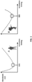
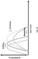
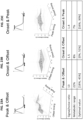
- a one-size-fits-all approach leads naturally to a high variability in the results. For example, as shown in FIG. 1 , while the best actuation timing for subject A which minimizes the metabolic cost of walking is AA, another subject B may have a totally different metabolic landscape and a totally different optimum at BB.
- the controllers presented in this disclosure may automatically find the optimal control parameter for each subject by solving an optimization problem in real time while walking with the wearer, leading to a maximum effect of the exosuit.
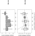
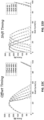
- FIG. 2A and FIG. 2B illustrate experimental results showing a change in metabolic rate for 7 different subjects.
- FIG. 2A depicts average changes (gray bars) and corresponding s.e.m. (error bars).
- FIG. 2B depicts individual subject data (colored lines) and corresponding box plots.
- FIG. 2A in this study our soft exosuit allowed for an average reduction of -15% of the net metabolic cost of walking in the best condition (Max-Neg).
- FIG. 2A in this study our soft exosuit allowed for an average reduction of -15% of the net metabolic cost of walking in the best condition (Max-Neg).
- FIG. 2A in this study our soft exosuit allowed for an average reduction of -15% of the net metabolic cost of walking in the best condition (Max-Neg).
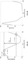
- FIG. 3A and FIG. 3B illustrate experimental results showing change in metabolic rate for 9 different subjects.
- Five different spring conditions for unpowered exoskeletons were tested and are presented along the x-axis.
- FIG. 3A depicts average changes (gray bars) and corresponding s.e.m. (error bars).
- FIG. 3B depicts individual subject data (colored lines) and corresponding box plots.
- the unpowered exoskeleton allowed for an average metabolic reduction of -7% in the best stiffness condition (182 N m rad-1).
- the individual reduction varied from +4% to -23% in the same condition, and inter-subject variability was pretty significant for all of the experimental conditions.
- US2010/114329A1 discloses hybrid terrain-adaptive lower-extremity apparatus and methods that perform in a variety of different situations by detecting the terrain that is being traversed, and adapting to the detected terrain.
- a wearable system according to the invention is defined in claim 1.
- one or more actuation parameters of an assistive profile may be adjusted to maximize or minimize an objective function associated with one or a combination of: (i) providing physical assistance to the wearer, (ii) an interaction between the wearer and the exosuit or the exoskeleton, and (iii) an operation of the exosuit or the exoskeleton.
- the systems and methods of the present disclosure may be widely applied to wearable systems designed to assist healthy wearers and wearers with physical/neurological impairments alike.
- actuation timing e.g., onset, peak, offset
- actuation amplitude e.g., maximum, minimum
- actuation rate e.g., slow, fast
- actuation profile shape e.g., function coefficients affecting shape of polynomial-, linear-, exponential-, sinusoidal-, or spline-shaped actuation profiles
- locomotive economy e.g., minimizing energy expenditure of locomotion
- locomotive output e.g., maximizing propulsion
- locomotive form e.g., maximizing gait symmetry, maximizing ground clearance
- stability whether stationary or moving.
- various actuation parameters can be adjusted to maximize or minimize objective functions associated with interactions between the exosuit or exoskeleton and the wearer such as displacement of the exosuit or the exoskeleton on the wearer (e.g., minimize displacement) and comfort of the wearer (e.g., minimize shearing forces and/or pressure points).
- systems and methods of the present disclosure provide for optimizing one or more actuation parameters for maximizing or minimizing objective functions associated with the exosuit or exoskeleton itself such as electrical power consumption (e.g., minimizing battery power consumption), mechanical power transmission efficiency (e.g., maximizing force delivered to the exosuit by the actuator), and temperature (e.g., minimizing temperature of one or more components of the exosuit or the exoskeleton).
- an objective function may be used to combine more than one variable that is desired to optimize, through a weighted average of two or more variables, or other methods.
- the objective function can be evaluated using one or more wearable sensors, thereby facilitating use outside of laboratory environments.
- the wearable sensor(s) may directly measure the objective function, while in other embodiments, the controller may use measurements from the wearable sensor(s) to calculate or otherwise approximate the objective function (e.g., measure force and rotational velocity to calculate power delivered to the wearer).
- Example wearable sensors include one or a combination of an inertial measurement unit (IMU), a joint angle sensor, a force or pressure sensor, a torque sensor, a metabolic energy measurement device, a muscle activity measurement device, a ground reaction force sensor, a heart rate sensor, and an insole force or pressure sensor, amongst others.
- IMU inertial measurement unit
- systems and methods of the present disclosure may monitor a proxy that has a correlative relationship with the objective function in order to evaluate the objective function.
- experimental data shows that average positive power delivered to the wearer by the exosuit or exoskeleton tends to correlate with locomotive efficiency and locomotive output of the wearer; therefore, average positive power a useful proxy for evaluating locomotive efficiency and locomotive output as objective functions.
- Optimization approaches may generally include actuating the exosuit or exoskeleton according to at least one actuation profile, evaluating the objective function based on information measured by at least one sensor, adjusting at least one parameter of the actuation profile based on a resulting change in the objective function, and continuing to actuate, evaluate, and adjust to optimize the actuation parameter(s) for maximizing or minimizing the objective function.
- a gradient-descent approach may be used to optimize the actuation parameter(s) for maximizing or minimizing the objective function.
- a gradient-descent approach typically leads to convergence, and is often simple and low in computational burden, making it well suited for running on inexpensive processors or when running other computationally-burdensome processes on shared hardware.
- the controller may be configured to determine whether the objective function increased or decreased from one or an average of preceding evaluations of the objective function, and in response, adjust the actuation parameter in a same or different direction depending on whether it is sought to maximize or to minimize the objective function.
- the controller may be configured to compare evaluations of the objective function for each actuation profile to determine which produces the highest or lowest evaluation of the objective function, and in response, generate another set of actuation profiles in which the values of the actuation parameters being optimized have been adjusted according to a derivative of the objective function evaluations associated with the former set of actuation profiles.
- a gradient-descent approach may optimize the actuation parameter(s) to a local maximum/minimum or a global maximum/minimum depending on the objective function landscape (i.e., relationship between the objective function and the parameter(s) being optimized).
- a gradient-descent approach may optimize the actuation parameter(s) to a global maximum/minimum of the objective function.
- the gradient-descent approach may optimize the actuation parameter(s) to either a local maximum/minimum or to a global maximum/minimum depending on where the optimization starts, amongst other relevant factors.
- a Bayesian approach may be used to optimize the actuation parameter(s) for maximizing or minimizing the objective function.
- a Bayesian approach is typically sample-efficient, allowing it to explore the objective function landscape relatively quickly. This feature can make a Bayesian approach well-suited for finding and optimizing the actuation parameter(s) to a global maximum/minimum in more complex objective function landscapes, and tends to make a Bayesian approach relatively more tolerant of noise in evaluations of the objective function than some other approaches.
- a mathematical correlation between the actuation parameter(s) and the objective function can be defined by actuating the exosuit or exoskeleton according to several actuation profiles having different baseline values of the actuation parameter(s) being optimized and mapping corresponding evaluations of the objective function for each. From this, the controller may determine a candidate value(s) of the actuation parameter(s) for maximizing or minimizing the objective function. The candidate value(s) may be tested and evaluated, and the mathematical correlation updated, until the controller converges on an optimized value of the actuation parameter(s), or until some other suitable termination criteria is met.
- the process of defining the mathematical correlation and identifying candidate values of the actuation parameter may involve generating a posterior distribution (e.g., via a Gaussian process, in an embodiment) and utilizing a probabilistic model (e.g., a Bayesian approach) to identify a candidate value(s) of the actuation parameter based on the posterior distribution.
- a Bayesian approach may optimize the actuation parameter(s) to a local maximum/minimum or a global maximum/minimum depending on the objective function landscape and where the optimization starts, amongst other relevant factors.
- the assistive profiles of these type of wearable devices have been designed following methodologies that include i) commanding a pre-defined assistive profile based on biomechanics knowledge from studies that involve multiple participants, ii) off-line simulation of different assistive profiles given a typical movement of the wearer from average or normative biomechanics, iii) experimental evaluation of different profiles on multiple subjects by following time-consuming biomechanical studies and selection of the profile that, in average, provides higher benefits in average. All these approaches may lead to promising results in average for the conditions that they have been designed for but may result in high inter-subject variability and are very dependent on the task that they have been designed for (e.g., a treadmill speed or a way of performing a given task).
- FIG. 4 illustrates how two different healthy individuals may have different outcomes depending on the actuation parameters selected (in this case actuation timing), the maximum performance of the system, in this case the lowest metabolic cost of walking, is achieved with very different actuation parameters for each subject.
- optimization approaches may be used to maximize or minimize benefits when wearing a lower-limb exoskeleton or exosuit during walking.
- the proposed system may assist different joints in the lower-limb such as the ankles, knees or hips during walking to either enhance the performance of healthy individuals during walking (e.g. reducing fatigue) or to correct gait deficits and improve the efficiency of walking for impaired individuals.
- walking is a cyclic task in which an optimization algorithm may be able to measure or estimate an objective over multiple steps, modify a parametrized assistive profile, re-evaluate the objective and iterate until the parameters that maximize of minimize the desired objective are found.
- optimization approaches that involve the lower extremity of the body, for example, that can assist the gait of the wearer
- various other types of motion and movement of the body of the wearer can be affected and optimized using optimization approaches in conjunction with the exosuit or exoskeleton.
- other non-walking tasks that are either cyclic in nature, involve multiple repetitions, or that are sustained over time can utilize an optimization algorithm to maximize or minimize an objective function that is evaluated during each repetition or over time respectively.
- Exemplary cyclical upper body movement can include exercise in rehabilitation or repetitive work tasks.
- Activities involving the upper body including, but not limited to, the arms, neck, hands, wrists, shoulders, and/or back, can be enhanced by wearing assistive wearable devices, such as an exosuit or an exoskeleton, which can reduce fatigue, strains and/or injuries.
- assistive wearable devices such as an exosuit or an exoskeleton
- support can be provided to the lower back, shoulder, elbow, arm and/or hand when either lifting objects or performing over-head work, or a grip assist device can provides additional strength in wrist and/or the hand to either grasp a tool or press a trigger of a tool to avoid strains on muscles or carpal-tunnel symptoms if repeated.
- wearable devices can be applied to wearers to reduce fatigue, improve ergonomics, prevent injuries, or improve comfort while doing these tasks.
- Wearable devices can be optimized and used on or across various joints of the wearer including, but not limited to, an ankle, knee, hip, back, neck, shoulder, elbow, hand, or combinations of aforementioned joints. As these tasks are characterized by having multiple repetitions or being sustained over a period of time, various optimization methods can be used to measure and/or estimate an objective function over multiple repetitions or over time respectively and update a parametrized assistive profile to optimize a desired objective.
- an optimization approach may generally entail:
- Systems and methods of the present disclosure seek to optimize one or more parameters associated with actuating the exosuit or exoskeleton in order to maximize or minimize the selected objective function.
- the exoskeleton or exosuit is actuated according to an actuation profile defining a timing, rate, magnitude, and overall shape of the actuation during a specified period.
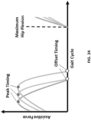
- an actuation profile is presented in the form of commanded actuator position (e.g., cable position when a Bowden cable(s) connects a motor(s) to portion(s) of the exosuit or exoskeleton) throughout the specified period, as shown in FIG. 5B , that determines the shape of the assistance force profile as shown in FIG. 5A .
- An actuation profile can also be based on force control as shown in FIG. 5C .
- the specified period is a cycle of the wearer's gait, which can be a useful timeframe when assisting the lower limbs of the wearer during locomotion.
- any suitable period may be specified according to the biomechanics of the wearer and the portion(s) of the wearer's body being assisted by the exosuit or exoskeleton.
- an actuation profile can be broken down according to the prescribed timing, rate, magnitude, and overall shape of actuation. More specifically, an actuation profile can be further reduced into a finite-dimensional set of numerical variables, representing key actuation parameters such as: (i) the timing of the initiation of actuation, of its peak, and of its termination, (ii) a rate of the actuation, (iii) the magnitude of the actuation, and (iv) coefficients of a function defining a shape of the actuation, such as the coefficients of a polynomial, linear, exponential, sinusoidal, or other function defining a shape of the actuation profile.
- key actuation parameters such as: (i) the timing of the initiation of actuation, of its peak, and of its termination, (ii) a rate of the actuation, (iii) the magnitude of the actuation, and (iv) coefficients of a function defining a shape of the actuation, such as the coefficients of
- Actuation of the exosuit or exoskeleton in combination with the natural motion of the wearer causes the exosuit or exoskeleton to deliver forces and moments to the wearer's body.
- the timing and magnitude of the resulting forces and moments may be characterized by a position assistance profile, as shown in FIG. 5B .
- actuation of the exosuit or exoskeleton according to the actuation profile of FIG. 5A delivers forces and moments to the wearer's hip as represented in the assistance profile of FIG. 5B .
- the assistive profile may be parametrized directly in the force or torque space to be controlled by a force controller as shown in FIG. 5C .
- the actuation is configured to assist an extension motion of the wearer's hip joint while walking.
- a common goal of the optimization approaches disclosed herein is to maximize the benefits conferred by the exosuit or exoskeleton to the wearer.
- These benefits may vary depending on the given application, but generally speaking, involve providing physical assistance to the wearer. This can include, for example, assisting the wearer's natural motions (e.g., reducing energy expenditure, increasing strength), helping to stabilize the wearer while stationary or moving, or promoting an improvement in a cyclical or repetitive motion of the wearer (e.g., retraining gait in stroke patients), amongst any number of other suitable uses.
- optimization approaches of the present disclosure seek to optimize one or more parameters of how the exosuit or exoskeleton is actuated with the purpose of maximizing or minimizing these metrics, or objective functions.
- Systems and methods of the present disclosure utilize feedback from one or more sensors of the wearable system to evaluate the impact of actuation adjustments on a given objective function. This feedback helps the wearable system ensure that these actuation adjustments converge in a way that maximizes or minimizes the objective function.
- the controller may be configured to evaluate the objective function in response to a given actuation of the exosuit or exoskeleton.
- evaluating the objective function broadly includes any suitable way of quantifying the objective function.
- evaluating the objective function may be obtaining a direct measurement of the objective function from the one or more sensors included in the wearable system.
- evaluating the objective function may include calculating or approximating the objective function using one or more measurements provided by the one or more sensors of the wearable system. For example, if the objective function is power delivered by the exosuit or exoskeleton to the wearer, the controller may be configured to calculate power by multiplying measurement of force and rotational velocity taken by a load cell and IMU to calculate this metric. In yet another embodiment, evaluating the objective function may include measuring, calculating, or approximating a proxy correlated with the objective function using information measured by the one or more sensors of the wearable system to estimate, via this correlative relationship, the objective function.
- a proxy in evaluating the objective function may be particularly well-suited to situations in which it may be impossible or otherwise difficult to directly measure the objective function, or to estimate the objective function via calculations using related measurements from wearable sensors. For example, it can be difficult to directly measure metabolic consumption, and typically requires expensive equipment or requires the user to wear a mask to measure gas exchange. However, the amount of positive power that an exosuit or exoskeleton delivers to the ankle joint during plantarflexion has been found to correlate with a reduction in metabolic cost. Therefore, an optimization algorithm may use positive power delivered to the biological joint as a proxy for evaluating metabolic cost, locomotive efficiency, and other related objective functions.
- an objective function as the term is used herein, need not always describe the ultimate desired effect (e.g., maximize locomotive efficiency) but rather can be any metric sought to be maximized or minimized (including, within a set of range constraints) through optimization of one or more actuation parameters.
- heart rate has also been found to be correlated with a level of exertion of wearers in some applications, and therefore heart rate, in an embodiment, may be used as a proxy for metabolic effort.
- heart rate in an embodiment, may be used as a proxy for metabolic effort.
- estimating the overall stability of human walking overground can be very challenging; however as further described in more detail below, there exists some low-dimensional quantities such as extrapolated center of mass and the maximum Lyapunov exponent (MLE), which correlate with the wearer stability and thus, in an embodiment, can be used as a proxy for evaluating stability.
- MLE Lyapunov exponent
- objective functions related to exosuits or exoskeletons may be broken down into three categories: (i) those objective functions associated with providing physical assistance to the wearer, (ii) those objective functions associated with an interaction between the wearer and the exosuit or exoskeleton, and (iii) those objective functions associated with the operation of the exosuit or exoskeleton, as further described in more detail below. It should be understood, of course, that these categories are presented for ease of explanation, and that the optimization approaches described herein may also be used in connection with optimizing actuation for maximizing or minimizing any other suitable objective function that may fall outside of the scope of one of these three general categories.
- Energy Expenditure Quantifies the energy consumption or level of effort when performing a task.
- a system that measures this variable may use this as an objective function to an algorithm to reduce the metabolic effort of a given task (e.g. walking, running, lifting an object, etc.). This metric may be useful for a wide variety of applications such as healthy people doing strenuous tasks or impaired individuals with reduced walking efficiency.
- This objective function may also be referred to herein as metabolic effort or, in the context of locomotion, locomotive efficiency.
- Ground Clearance Measurement of the shortest distance between the foot and the ground.
- An exemplary optimization approach may seek to optimize an actuation parameter(s) to maximize the distance between the foot and the ground in order to minimize instances of toe-catching in patients with foot drop or when carrying heavy loads.
- a related objective function based on this measurement, and blending aspects of both ground clearance and gait symmetry, is the ratio or symmetry index of ground clearance between both legs, which could be useful for applications such as stroke where one leg is mostly affected.
- An exemplary optimization approach may evaluate how similar a wearer's kinematics are to age-, sex, weight-, and/or speed-matched data from a normative set of healthy users, and optimize an actuation parameter(s) to drive the wearer's kinematics to match (i.e., maximize similarity to or minimize variance from) a desired normative profile.
- Possible metrics include correlation with healthy data or percent difference in key points or metrics (e.g. ankle kinematics during ground clearance).
- Time integral of muscular activity This is the integral with respect to time of the muscular activity.
- An exemplary optimization approach may seek to optimize an actuation parameter(s) to reduce or minimize the overall activity of the muscle(s) during an activity. For instance, one may desire to reduce or minimize the overall effort of calf muscles during walking, or muscles in the back when lifting an object.
- Peak muscular activity Similar to time integral of muscular activity, but targeting peak muscle activity. This may be chosen over or in combination with time integral of muscular activity in some applications, for instance for activities in which the peak muscular activity may pose a risk of injury or in which the peak muscle activity is higher than a person is able to perform for a long time.
- Time integral of forward propulsion (propulsive impulse): This is the integral with respect to time of the component of the ground reaction force pointing in the direction of locomotion.
- An exemplary optimization approach may seek to maximize this objective function in order to increase propulsive efficiency. This optimization could be done for just one leg (as in stroke, where the objective may be to enhance paretic propulsive impulse) or both legs.
- Peak propulsive force This is the maximum value of the ground reaction force pointing in the direction of walking.
- An exemplary optimization approach may seek to maximize this objective function in order to increase propulsive or locomotive output. This optimization could be done for just one leg (as in stroke, where the objective may be to enhance paretic propulsive impulse) or both legs.
- Ratio of propulsive impulse to braking impulse Propulsive impulse is measured as described above, while the braking impulse is the time integral of the component of the ground reaction force that points opposite the direction of walking. For steady-state walking in healthy populations, this ratio is approximately one for each leg.
- An exemplary optimization approach may seek to optimize an actuation parameter(s) to drive this ratio towards one for each leg (i.e., maximize similarity between propulsive impulse and braking impulse for a given leg).
- Propulsion impulse symmetry This is expressed as either a ratio between the propulsion impulse of both legs, or a "symmetry index" where a value of one suggests "healthy-like" locomotion.
- An exemplary optimization approach may seek to optimize an actuation parameter(s) to drive this ratio or symmetry index between legs towards one (i.e., maximize similarity between propulsion impulse of the legs).
- Peak propulsion symmetry This is either a ratio between the peak propulsion of both legs, or a "symmetry index" where a value of one suggests "healthy-like" locomotion.
- An exemplary optimization approach may seek to optimize an actuation parameter(s) to drive this ratio or symmetry index between legs towards one (i.e., maximize similarity between peak propulsion of the legs).
- Timing of the transition from braking to propulsion During the gait cycle, each foot switches from braking (forces pointing opposite the direction of walking) and propulsion (forces pointing in the direction of walking). In healthy locomotion, the timing of this transition is the same in either foot's gait cycle.
- An exemplary optimization approach may seek to optimize an actuation parameter(s) to minimize variance in the transition timing of each foot relative to the other during locomotion. Additionally or alternatively, another exemplary optimization approach may identify an optimal transition timing for maximizing or minimizing a related objective function (e.g., locomotive efficiency, locomotive output) and seek to minimize variance from the optimal timing.
- An exemplary optimization approach may evaluate how similar a wearer's ground reaction forces are to age-, sex, weight-, and/or speed-matched data from a normative set of healthy users, and optimize an actuation parameter(s) to drive the wearer's kinematics to match (i.e., maximize similarity to or minimize variance from) a desired normative profile.
- Possible metrics include correlation with healthy data or percent difference in key points or metrics (such as peak propulsion and propulsive impulse, as defined above).
- Stability during locomotion An exemplary optimization approach may seek to optimize an actuation parameter(s) to maximize joint stability or overall body stability during locomotion. Estimating the overall stability of a human during locomotion can be very challenging. However, some measurements may sufficiently correlate with stability to function as proxies therefor, such as low-dimensional quantities, extrapolated center of mass (CP) and the maximum Lyapunov exponent (MLE). These metrics can be used as part of an optimization strategy to improve stability during walking for patients or healthy individuals performing complex or strenuous tasks.
- CP extrapolated center of mass
- MLE maximum Lyapunov exponent
- Joint range of motion An exemplary optimization approach may seek to optimize an actuation parameter(s) to maximize the range of motion for a particular joint.
- the range of motion is typically defined as the difference between the maximum and minimum angle of a given joint in a given plane of motion, but the maximum and minimum angles may also be of interest for optimization.
- the ankle's range of motion in the sagittal plane is the peak plantarflexion angle minus the peak dorsiflexion angle, but an algorithm may seek to optimize just the maximum dorsiflexion angle.
- Foot placement, step length and step width This measures the location of one foot relative to another. Users with impaired balance or stability may walk with wider step width and shorter step length than healthy people, so an exemplary optimization approach may seek to optimize an actuation parameter(s) to minimize step width and/or maximize step length. Additionally or alternatively, another exemplary optimization approach may seek to optimize an actuation parameter(s) to maximizing symmetry (or minimize variance) between step width for both legs. Foot placement can be measured directly via motion capture or ground reaction forces on a force place (by looking at the position of the foot's center of pressure), or estimated using IMUs.
- An exemplary optimization approach may seek to optimize an actuation parameter(s) to minimize the time required to perform a repetitive task such as lifting loads, moving packages from one place to another in a factory environment, etc.
- Trailing limb angle during terminal stance This is the angle between the global vertical axis and the line defined by a point on the pelvis (often the greater trochanter or the hip joint center) and a point on the stance foot (often the fifth metatarsal head or the center of pressure).
- people with impaired gait may have a lower trailing limb angle during terminal stance.
- An exemplary optimization approach may seek to optimize an actuation parameter(s) to maximize trailing limb angle, for example, in situations where it is desired to increase forward propulsion.
- another exemplary optimization approach may seek to optimize an actuation parameter(s) to minimize trailing limb angle, for example, in situations where it is desired to increase stability.
- Vertical center of mass travel Movement of the wearer's center of mass in the vertical direction may be directly measured either by motion capture or force plates. However, it is also possible to approximate an acceleration of the wearer's center of mass using trunk- or pelvis-mounted IMUs, and integrating twice with respect to time yields an evaluation of the position of the wearer's center of mass. Total travel of the center of mass in the vertical direction may be positively related to the metabolic cost of walking, so this metric could be used as a proxy for evaluating related objective functions (e.g., locomotive efficiency). An exemplary optimization approach may seek to optimize an actuation parameter(s) to minimize vertical center of mass travel, for example, in situations where it is desired to maximize locomotive efficiency.
- Center of mass power is the vector product of center of mass velocity and total ground reaction force. It can be measured directly using force plates and/or motion capture, or estimated by wearable sensors by approximating the acceleration of the wearer's center of mass as outlined above and then estimating total ground reaction force using that acceleration and overall body mass. Center of mass power may be positively related to the metabolic cost of walking, so this metric could be used as a proxy for evaluating related objective functions (e.g., locomotive efficiency).
- An exemplary optimization approach may seek to optimize an actuation parameter(s) to minimize center of mass power, for example, in situations where it is desired to maximize locomotive efficiency.
- Similarity of center of pressure location of the foot to normative data In healthy walking, the center of pressure follows a well-known trajectory through the foot.
- An exemplary optimization approach may seek to optimize an actuation parameter(s) to maximize similarities (or minimize variance) between a trajectory of the wearer's center of pressure and that of a desired normative trajectory.
- Center of pressure may be measured using force plates, or estimated by wearable sensors, such as an instrumented shoe insole.
- Total pressure of the foot during push-off Like center of pressure, the total pressure exerted by the foot may be measured using force plates or estimated by wearable sensors, such as an instrumented shoe insole. The total pressure tends to correlate with the total ground reaction force (GRF), which in turn correlates with forward propulsive force when evaluated during a push-off phase of locomotion. Accordingly, total pressure could be used as a proxy for evaluating forward propulsion.
- An exemplary optimization approach may seek to optimize an actuation parameter(s) to maximize total pressure of the foot during a push-off phase of locomotion, for example, in situations where it is desired to increase forward propulsion.
- NIRS near-infrared spectroscopy
- Muscle contraction/strain and tendon strain Wearable exosuits and exoskeletons can affect how muscles contract and muscle/tendons strain under load.
- An exemplary optimization approach may seek to optimize an actuation parameter(s) to maximize or minimize these physiological parameters, or to limit them to certain values or ranges.
- contraction/strain is often related to the energetic metabolic demand of the corresponding muscle, so this metric may be a suitable proxy for evaluating related objective functions (e.g., energy expenditure, locomotive efficiency).
- An exemplary optimization approach may seek to optimize an actuation parameter(s) to minimize muscle contraction/strain and tendon strain, for example, in situations where it is desired to minimize energy expenditure or maximize locomotive efficiency.
- Ultrasound or acoustic imaging may, in some embodiments, be used as a way to non-invasively measure tissue movement.
- Exemplary optimization approaches may utilize information associated with associated with providing physical assistance to the wearer in evaluating these objective functions. For example, in some embodiments, the controller may evaluate these objective functions using direct measurements of the objective functions themselves, while in other embodiments, the controller may evaluate these objective functions by calculating or approximating the objective function using various measurements of related metrics from one or more wearable sensors or other measurement equipment.
- representative information associated with these objective functions may include any such information described above, as well as one or a combination of an angle, velocity, or acceleration of one or more joints; a force, torque, or power applied by the exosuit or the exoskeleton; a type of physical activity in which the wearer is engaged; a posture of the wearer; an energy expenditure of the wearer; and an interaction of the wearer's body with a surrounding physical environment.
- Representative sensors for measuring said information for evaluating the objective function may include, in various embodiments, inertial measurement units (IMUs), accelerometers, gyroscopes, encoders, resolvers, strain sensors, heart rate monitors, pulmonary gas exchange systems, electromyography, pressure sensors (e.g., in a footwear insole for measuring GRFs), and an instrumented treadmill, amongst other suitable sensors.
- IMUs inertial measurement units
- many objective functions associated with exosuit or exoskeleton performance relate to interactions between the exosuit or exoskeleton and the wearer. As further described below, such interactions may relate to things like wearer comfort and the effectiveness of the wearable system in transmitting loads to the wearer, amongst others. Representative examples of several such objective functions are provided below, along with biomechanical context for how each may be maximized or minimized to benefit the wearer.
- An exemplary optimization approach may seek to optimize an actuation parameter(s) to minimize displacement (or maximize alignment) of the exosuit or exoskeleton (including individual components thereof, such as anchor members) on the body of the wearer.
- Displacement of the suit components with respect to the body may be measured by using wearable sensors such as IMUs. For instance by using two IMUs, one of them IMU integrated in a suit component and another sensor attached to the body and integrating measurements such as the relative speed or acceleration.
- relative displacement may be estimated by combining the of exposed cable (e.g.
- the amount of exposed cable is a function of the cable required to track the joint movement, the stiffness of the suit and the compliance of the interface. If the displacement is measured at points of the gait cycle in which there is no active force applied to the person (only pretension or tracking without applying force), the stiffness of the suit will have no effect on the cable travel and therefore the displacement may be calculated by combining the cable movement due to the joint angle (translated to displacement by multiplying by the distance from the joint center of rotation and the cable, which could be a constant or an input to the device) and the total exposed cable measurement.
- relative displacement may be estimated by using the motor encoder and comparing the exposed cable at repeatable points in the gait cycle over multiple steps such as mid-stance giving an estimation of how much the suit components has displaced with respect to the body over different steps.
- An exemplary optimization approach may seek to optimize an actuation parameter(s) to maximize comfort of the wearer (or to minimize a particular discomfort experienced by the wearer).
- potential discomfort can be automatically detected by the controller by, for example, monitoring forces in the exosuit or exoskeleton or by monitoring pressures between the exosuit or exoskeleton and the wearer, and comparing these forces and/or pressures to levels of each that are known to cause discomfort in the individual wearer, or across a representative sampling of wearers.
- a representative optimization approach may seek to optimize an actuation parameter to reduce those forces to within an acceptable range (while still, perhaps, maximizing the level of forces generated within the acceptable range).
- a representative optimization approach may seek to optimize an actuation parameter to reduce those shear forces to within an acceptable range (while still, perhaps, maximizing the level of forces generated within the acceptable range).
- this may involve reducing the level of force generated by the exosuit or exoskeleton, or perhaps increasing a compressive force within the exosuit or exoskeleton to better anchor the troubling anchor member to the underlying body part. Similar approaches may be taken to optimizing an actuation parameter to reduce pressure points generated by an interaction of the exosuit or exoskeleton and the wearer, as further described below. Additionally or alternatively, comfort may be self-reported through a GUI, hand-held device, voice, pressure measurements, or the like.
- An exemplary optimization approach may seek to optimize an actuation parameter(s) to minimize pressures applied to some areas of the wearer's body that may be sensitive to discomfort caused by the textile or rigid interface with the exosuit or exoskeleton. This may maximize comfort (or minimize discomfort) while, for example, still maximizing assistance within those comfort levels. This pressure may be affected by actuation parameters such as the timing, rate, the jerkiness of the profile or magnitude of assistance.
- Load transfer along the wearer's body In some cases, it may be advantageous to utilize the exosuit or exoskeleton to help transfer loads away from one area of the wearer's body to another, for example, to help mitigate injuries.
- An exemplary optimization approach may seek to optimize an actuation parameter(s) to maximize load transfer from the area of the body at issue. This may be particularly useful in situations in which the wearer is lifting a heavy load and is thus susceptible to back injury.
- the controller may seek to optimize an actuation parameter(s) to minimize loads on the spine of the wearer. This may, in an embodiment, be accomplished by optimizing the actuation parameter(s) to maximize force transfer to other areas of the body such as the hips, torso or legs.
- Actuator force An exemplary optimization approach monitor interactions between the exosuit or exoskeleton, and upon detecting a large generated by the interaction, optimize an actuation parameter(s) to minimize a force generated by the actuator, so as not to deliver additional force that may cause discomfort or injury.
- the controller may, in optimizing the actuation parameter(s), also seek to keep other biomechanical constraints constant.
- Exemplary optimization approaches may utilize information associated with associated with an interaction between the exosuit or exoskeleton and the wearer in evaluating these objective functions.
- the controller may evaluate these objective functions using direct measurements of the objective functions themselves, while in other embodiments, the controller may evaluate these objective functions by calculating or approximating the objective function using various measurements of related metrics from one or more wearable sensors or other measurement equipment.
- representative information associated with these objective functions may include any such information described above, as well as one or a combination of a shearing or compression force generated between the wearer and the exosuit or the exoskeleton, and a position of the exosuit or the exoskeleton on the wearer.
- Representative sensors for measuring said information for evaluating the objective function may include, in various embodiments, load cells, force sensors, torque sensors, and pressure sensors, amongst other suitable sensors.
- An exemplary optimization approach may seek to optimize an actuation parameter(s) to minimize electrical power consumption. Electrical power consumption may be measured by combining electrical current draw measurement (via an integrated current sensor) and voltage (via an integrated voltage sensor), by multiplying those measurements electrical power can be calculated, the average power consumption over one step will give an estimation of how much electrical power is consumed per step. Another embodiment may use remaining battery voltage to estimate how much battery is left or how much battery has been consumed so far in the system..
- Consistency of Assistive Forces An exemplary optimization approach may seek to optimize an actuation parameter(s) to maximize consistency (or minimize variance) between assistive forces generated in the exosuit or exoskeleton. If an exosuit or exoskeleton aims to provide forces that are consistent in terms of peak force over multiple steps, a measurement of consistency may be the variance of the peak force or other features in the force profile that have to remain consistent over multiple steps. Forces may be measured by using wearable sensors such as force sensors or loadcells. Another embodiment may define consistency of assistive forces as the root mean square deviation of the measured force and the desired force profile, maximizing consistency of this difference over multiple steps may be used as an objective for these systems.
- Maximum and average actuator position, velocity, acceleration, or jerk Subject to kinematic or kinetic constraints measured as outlined above (e.g. peak dorsiflexion angle does not fall below a pre-set threshold, or propulsive impulse remains constant), it may be of interest to minimize these metrics related to how "hard" the suit is pulling. For example, an exemplary optimization approach could find the optimal parameter or set of parameters that minimize maximum cable acceleration without impacting the propulsive impulse.
- An exemplary optimization approach may seek to optimize an actuation parameter(s) to minimize a temperature of one or more components of the exosuit or exoskeleton. Like other objective functions described herein, minimizing the temperature may, in an embodiment, mean ensuring the temperature does not exceed an upper threshold of a predetermined range.
- Exemplary optimization approaches may utilize information associated with associated with operation of the exosuit or exoskeleton in evaluating these objective functions.
- the controller may evaluate these objective functions using direct measurements of the objective functions themselves, while in other embodiments, the controller may evaluate these objective functions by calculating or approximating the objective function using various measurements of related metrics from one or more wearable sensors or other measurement equipment.
- representative information associated with these objective functions may include any such information described above, as well as one or a combination of a current or a voltage used during actuation of the exosuit or the exoskeleton; a temperature of one or more components of the exosuit or the exoskeleton; a force generated by the at least one actuator; a force delivered to the exosuit or the exoskeleton; and a force, torque, or power delivered to the wearer of the exosuit or the exoskeleton.
- Representative sensors for measuring said information for evaluating the objective function may include, in various embodiments, current sensors, voltage sensors, thermistors, encoders and resolvers (e.g., for measuring actuator position, speed, and acceleration), amongst other suitable sensors.
- an objective function (or proxy function) needs not to represent a single variable associated with the motion or biomechanics of a wearer, but can combine multiple optimization targets.
- Multiple single-variable objective functions can be combined into a single one through different methods, such as weighted averaging, which allows to calibrate the relative importance of each component of the objective function.
- Some example weightings of two or more objectives within one objective function include:
- each metric may be different depending on the application. For instance for medical applications depending on each pathology, individual patient or the goals of a therapeutic session, the clinician or operator of the system may be able to modify these gains during a test. An example of this concept using weighted sum of objectives for impaired individuals is shown in FIG. 6 . For healthy population, individual users may be able to change these settings manually.
- Systems and methods of the present disclosure provide for optimizing one or a combination of these actuation parameters to maximize or minimize a selected objective function.
- Approaches seeking to optimize a single actuation parameter e.g., finding the optimal actuation onset timing
- approaches seeking to optimize a combination of actuation parameters e.g., finding the optimal combination of actuation onset timing and actuation peak timing
- multi-parameter optimization e.g., multi-parameter optimization.
- a number of factors may influence whether a single-parameter or multi-parameter optimization approach is used including, without limitation, the biomechanics of the wearer, the population wearing the exosuit or exoskeleton, the relative effect of each actuation parameter on the objective function, required optimization time, measurement noise, wearer adaption and available computing power, as further described below.
- known (or modified) methods for optimizing variables may be used or otherwise modified to optimize the targeted actuation parameter(s) to maximize or minimize a selected objective function.
- known (or modified) methods for optimizing variables e.g., gradient descent, Bayesian, brute force, and simulated annealing
- the best mathematical method for optimizing the actuation parameter(s) may vary depending on a number of factors including, without limitation, the nature of the objective function landscape relative to the actuation parameter(s) to be optimized, the biomechanics of the wearer, the population wearing the exosuit or exoskeleton, the relative effect of each actuation parameter on the objective function, required optimization time, measurement noise, wearer adaption and available computing power, as further described below.
- a simplified gradient descent approach may be employed to optimize the actuation parameter(s) to maximize or minimize the objective function.
- a gradient-descent approach typically leads to convergence, and is often simple and low in computational burden, making it well suited for running on inexpensive processors or when running other computationally-burdensome processes on shared hardware.
- the controller may be configured to determine whether the objective function increased or decreased from one or an average of preceding evaluations of the objective function, and in response, adjust the actuation parameter in a same or different direction depending on whether it is sought to maximize or to minimize the objective function.
- the controller may be configured to compare evaluations of the objective function for each actuation profile to determine which produces the highest or lowest evaluation of the objective function, and in response, generate another set of actuation profiles in which the values of the actuation parameters being optimized have been adjusted according to a derivative of the objective function evaluations associated with the former set of actuation profiles.
- a gradient-descent approach may optimize the actuation parameter(s) to a local maximum/minimum or a global maximum/minimum depending on the objective function landscape (i.e., relationship between the objective function and the parameter(s) being optimized).
- a gradient-descent approach may optimize the actuation parameter(s) to a global maximum/minimum of the objective function.
- the gradient-descent approach may optimize the actuation parameter(s) to either a local maximum/minimum or to a global maximum/minimum depending on where the optimization starts, amongst other relevant factors.
- Gradient descent method is particularly applicable in situations in which the noise to signal ratio is very low and the objective is measured in a repeatable way, if the noise of the measurement is high, even with a convex landscape, gradient descent may converge to points in the landscape that are non-optimal due to noise or unrepeatability in the measurements.
- a Bayesian approach may be used to optimize the actuation parameter(s) for maximizing or minimizing the objective function.
- a Bayesian approach is typically sample-efficient, allowing it to explore the objective function landscape relatively quickly. This feature can make a Bayesian approach well-suited for finding and optimizing the actuation parameter(s) to a global maximum/minimum in more complex objective function landscapes, and tends to make a Bayesian approach relatively more tolerant of noise in evaluations of the objective function than some other approaches.
- a mathematical correlation between the actuation parameter(s) and the objective function can be defined by actuating the exosuit or exoskeleton according to several actuation profiles having different baseline values of the actuation parameter(s) being optimized and mapping corresponding evaluations of the objective function for each. From this, the controller may determine a candidate value(s) of the actuation parameter(s) for maximizing or minimizing the objective function. The candidate value(s) may be tested and evaluated, and the mathematical correlation updated, until the controller converges on an optimized value of the actuation parameter(s), or until some other suitable termination criteria is met.
- the process of defining the mathematical correlation and identifying candidate values of the actuation parameter may involve generating a posterior distribution (e.g., via a Gaussian process, in an embodiment) and utilizing a probabilistic model (e.g., a Bayesian approach) to identify a candidate value(s) of the actuation parameter based on the posterior distribution.
- a Bayesian approach may optimize the actuation parameter(s) to a local maximum/minimum or a global maximum/minimum depending on the objective function landscape and where the optimization starts, amongst other relevant factors.
- Bayesian optimization is more likely to find a global optimum since it performs a global search of the landscape based on the posterior distribution as opposed to only looking locally and comparing points that are relative close to each other like the gradient descent does.
- a Bayesian optimization approach is therefore particularly useful in situations in which the landscape of the objective function is complex, when there are multiple parameters to be optimized and therefore search efficiency is important or when the measurements of the objective function are noisy (e.g. metabolic measurements).
- the optimization may run until the objective function is truly maximized or minimized; however, in other embodiments, the optimization process may be further subject to additional or alternative termination criteria.
- the optimization algorithm may be configured to terminate when one of the following predefined termination criterion occurs: (i) a difference between evaluations of the objective function for successive adjustments to the at least one parameter of the at least one actuation profile falls below a predetermined threshold, (ii) a difference between successive adjustments to the at least one parameter of the at least one actuation profile falls below a predetermined threshold, (iii) a predefined amount of time since the start of optimization has been exceeded, (iv) the wearer exceeds a predefined number of steps since the start of optimization, and (v) a termination command issued by the wearer.
- Metabolic consumption has been traditionally measured by using a gas exchange measurement system, however this measurement requires the user to wear a mask during walking.
- the energetics of walking is influenced by the work done by muscle at joints.
- the exosuit delivers positive power to the ankle during late stance, the wearer' forward propulsion will be assisted which will contribute to reduce the metabolic cost of walking. This principle is applicable to other joints and other types of assistance as well.
- FIG. 7 shows the correlation between positive power delivered by the exosuit measured using by wearable sensors and the metabolic benefit that users had when measured by a gas exchange system which suggests that average positive power delivered by the wearable robot can be used as a proxy to optimize metabolic effort. This is further validated by the results shown below which improved metabolic performance of multiple users by targeting average positive power delivered to the joint.
- This function is a proxy objective measure, available in real-time, in lieu of a direct measure of metabolic benefit.
- Control variable Actuation onset timing
- Actuation onset was selected as a parameter for the optimization process since it's a key variable when evaluating metabolic reduction during ankle assistance and its timing influences the amount of positive power delivered to the ankle joint. Contribution to positive power of the ankle joint starts during the push-off phase when the ankle angular speed becomes positive; starting to apply force to the joint earlier than that time may maximize the average positive power because there will be additional force at the cable by the time the joint starts to perform positive power. However, starting too early may result in a reduced speed of the ankle joint which will have negative effects in the amount of positive power that the system delivers during the push-off phase.
- FIG. 9A and FIG. 9B show (1) that the objective function landscape is convex and (2) that the onset of actuation has a big impact on the average positive powered and on the metabolic reduction of the different assistive profiles.
- FIG. 10A, FIG. 10B , and FIG. 10C show the motor/cable position, resulting force and power delivered to the user for different values of T1, as it can be seen in this figure, T1 has a big impact in the amount of power delivered to the human joint.
- variable to be optimized in this embodiment is the timing when the controller starts active cable retraction -- marked in FIG. 8B .
- the gradient descent method is a first-order iterative optimization algorithm, which finds a local optimum by iteratively estimating a function gradient at the current point and perturbing the independent variable in steps proportional to the gradient magnitude.
- the gradient can be estimated by applying several adjacent control parameter settings to the wearer while measuring/estimating the objective function and its local landscape.
- the average positive power delivered usually shows a convex shape with respect to T1 (actuation onset).
- the gradient descent process may converge on a local maximum (e.g., a localized peak in the overall convex landscape) or to a global maximum (e.g., the peak in the overall convex landscape).
- FIG. 11A, FIG. 11B, FIG. 11C , FIG. 11D , AND FIG. 11E show an example of execution of the present algorithm with a healthy male subject. Subject walked on a treadmill at 1.25 m/s for 8 minutes while wearing a multi-articular soft exosuit controlled by the algorithm described above. As shown in these figures, the control variable T1 successivefully converged to a specific value (44.75%), during the convergence process, the objective function for the identified optimal resulted in 7 W which is about 1.8 times greater than the initial value when the algorithm started.
- a human subject experiment has been conducted, where subjects walked on a treadmill at 1.5 m/s with a 15 Kg backpack wearing an exosuit assisting with ankle plantarflexion.
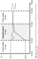
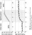
- the experiment consisted of 13 min continuous walking trials, including an initial state (4 min), an optimization period (5 min), and a final state (4 min).
- the controller kept the actuation onset timing (T1) constant at a given initial value, either 30% or 45% of the gait cycle, which is a relatively early or late actuation onset timing.
- the controller ran the developed optimization controller to find the optimal actuation onset timing that maximizes the average positive power delivered at ankle while keeping the peak force level constant. Then, during the final state, the controller kept the actuation onset timing constant again, at the optimal value found during the optimization period.
- FIG. 13 shows a representative result of the experiment from a subject (Subject A).
- the trial started with the actuation onset timing at 30% of the gait cycle.
- the controller ran the optimization controller by applying different actuation onset timings to the subject.
- the actuation onset timing (control variable) converged to 44% starting from 30% of the gait cycle, and by comparing the initial state and the final state, the average positive power delivered at ankle (objective function) significantly increased.
- FIG. 14 shows another representative result of the experiment from a different subject (Subject B). Similarly, the actuation onset timing (control variable) converged to 43% starting from 30% of the gait cycle, and by comparing the initial state and the final state, the average positive power delivered at ankle (objective function) greatly increased.
- FIG. 15 shows the metabolic rate of the subject while walking with 15kg backpack during the same experiment presented above. As shown, the metabolic cost gradually decreased while going through the optimization period. Comparing the initial state and the final state, the percentile metabolic reduction relative to the baseline condition (walking with powered-off exosuit) greatly increased from 14.4% to 22.9%.
- FIG. 16 shows the metabolic rate results of Subject B. Similarly, the metabolic cost gradually decreased, and comparing the initial state and the final state, the percentile metabolic reduction greatly increased from 10.7% to 19.6%.
- Bayesian optimization is a very efficient way of optimizing control parameters online, however, in some circumstances, it may be preferred to sacrifice efficiency by guaranteeing that the parameter space is explored in a gradual way.
- Gradient descent methods gradually explore the parameter space by changing from one point to another proximal point. This characteristic of gradient descent may be especially useful when a large change in the parameter space may result in a sudden change in the way the suit transmits forces to the user and may make the learning experience harder for the user to adapt to those transition, this may be especially applicable to users that are not trained to using wearable devices or for some patient populations.
- designers may choose to implement gradient descent methods, most likely sacrificing convergence time and performance under local minimum points for non-convex spaces.
- the following multi-dimensional optimization implementation has the goal of maximizing the average positive power delivered from the exosuit to the ankle joint.
- the following multi-dimensional optimization implementation has the goal of maximizing the average positive power delivered from the exosuit to the ankle joint.
- the selected optimization variable for this study are characterized by the onset of the assistive profile (when the cable starts to pull, which should be related to the start timing of push-off) and by the slope or duration of the assistance (how fast the cable pulls or the rate of cable pull, which should be relate to the ankle joint velocity during push-off).
- a gradient descent algorithm will have an initialization starting at a specific point in the parameter space (T1, D1).
- the algorithm will then iteratively estimate the gradient of the objective function at the current point and perturbing the independent variables in steps proportional to the gradient magnitude.
- the gradient can be estimated by applying multiple adjacent points in the parameter space and evaluating the objective function in each of them as explained in the single-parameter implementation.
- an objective function (such as a direct measure or indirect proxy for metabolic cost) will depend strongly on the entire profile of the assistance to be provided to the one or more joints of the wearer, and a one-dimensional simplification (such as the onset timing thereof) which keeps any other profile parameter constant may be insufficient to explore all the possible profile variations which could lead to an improved performance.
- the above-referenced provisional patent applications investigated how the onset and peak timing of hip extension assistance delivered by a lower-body soft exosuit affects the delivered positive mechanical power and metabolic cost during loaded walking.
- the study showed that two control variables (profile onset and peak timing) can both significantly and independently affect the amount of delivered mechanical power and metabolic reduction.
- the main results of this study are shown in FIG. 17A, FIG. 17B , and FIG. 17C .
- FIG. 17A shows the resulting assistive force profiles (average from eight subjects) shown on the right side of the figure.
- FIG 1B(M) shows the net metabolic cost reported in the unpowered condition (UNPD) and in the powered conditions. All data are means ⁇ SEM. The small panel on the right corner shows the corresponding assistive profile.
- FIG. 17C shows the positive mechanical power delivered by the soft exosuit to both limbs. All data are means ⁇ SEM. The braces with * represent statistically significant differences between two conditions (p ⁇ 0.05).
- the only viable way to use a one-dimensional optimization algorithm would be to fix one of the two parameters while optimizing the other, and then to repeat the same approach for any value of the first parameter in order to effectively explore the entire landscape of profiles. This would exponentially increase the required amount of optimization time by the number of open control variables, and by the number of assisted joints.
- onset and peak timings are not the only variables that determine how the subject receives assistance from the soft exosuit and the reduction of metabolic cost of walking.
- the entire shape and timing of the assistive profile needs to be defined to maximize the metabolic reduction, which means optimizing the entire shape of the profile.
- n variables are used to define the assistive profile, this leads the optimization to become an n-dimensional optimization problem.
- three control variables could be used to define a sinusoidal assistive profile for a single degree of freedom (DOF) as shown in FIG. 18 (amplitude, frequency, phase or time offset). In this case, a three-dimensional optimization method would be able to find the optimal profile.
- DOF degree of freedom
- the multi-dimensional optimization technique is not only preferable when tuning control variables in an exosuit, but it could also be advantageous in tuning the control systems of rigid exoskeletons and powered prostheses.
- the BiOM powered ankle prosthesis has 11 parameters governing its stiffness, the power and timing of the actuated push-off, and other functionality. Although high numbers of parameters make devices highly adaptable, they also make the selection of proper parameter values more difficult. Manually selecting those parameters experimentally are challenging to reach optimal.
- a method was developed to optimize multiple control parameters of an assistive actuation profile of an exosuit in order to (i) to find the optimal set of control variables for the soft exosuit for each subject, in order to (ii) to minimize or maximize the metabolic benefit for each subject.
- the goal for this method is to minimize or maximize an objective function which represents, or is an indirect measure, of the desired outcome from using the exouit.
- the goal of the multi-dimensional optimization method disclosed here is to find the optimal set of control variables values (within a pre-defined set of variables) to minimize or maximize the objective function for each subject.
- metabolic cost as the objective function can be used to optimize locomotion economy in healthy individuals.
- Using other objective functions for different purposes with this optimization is also viable. For example, to use the forward propulsion impulse symmetry or the gait symmetry (impaired vs. sound leg) as the target function when tuning exosuit control variables for improving the gait quality of a post-stroke individual. Or using indirect measurements (such as the delivered positive power) as a proxy to measure the metabolic cost of walking in order to make the optimization method viable for a portable soft exosuit system with body-worn sensors. Also, the result of max range of the hip angle times the step frequency can also be an objective function to utilize this optimization method to maximize the walking speed of the subject by optimizing those control variables.
- control variables for a multi-dimensional optimization can be any set of independent control parameters that affect the value of the objective function.
- Example control variables include but are not limited to assistance peak magnitude, assistance onset, peak, offset timing and multi-joint assistance correlation.
- a real-time optimization algorithm will try to find an optimal point in the n-dimensional space of the control variables (within predefined boundaries) in order to minimize or maximize a cost function.
- Measuring or estimating the objective function on the generated assistance profile typically corresponds to the individual wearing the exosuit walking for a pre-defined amount of time, and either a proxy function or a direct measure being taken.
- the initial evaluation points can be chosen from the n-scape of the control variables through several sampling methods. Generally speaking, the approach is that of sampling the n-dimensional space of the control parameters in order to have a reasonable initial estimation of the objective function landscape.
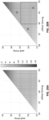
- FIG. 20A and FIG. 20B This approach is exemplified in FIG. 20A and FIG. 20B .
- the feasible region ( FIG. 20A ) - colored section) can be divided into 3 different control parameter regions ( FIG. 20B ). Then, for each region, a point ( FIG. 20B ) can be randomly selected.
- FIG. 20A and FIG. 20B show initial exploration point selection methods. Peak and offset timing presented as an example.
- colored space is a feasible space and different color corresponds to a different cost, shown by a right bar.
- FIG. 20B shows a sampling method.
- the algorithm may perform the following operations:
- the cost function can be either a direct measure or a proxy measure for the desired outcome (i.e., objective function) of the exosuit. Examples of this could be a direct measure of metabolic cost, a direct measure of gait symmetry, integral positive power at the ankle (a proxy measure for metabolic cost), etc. Any combination measure would be useable as well, provided it can be calculated in real time with the available sensors.
- the updated cost and the set of current evaluation points are then used to update a posterior distribution. This is done through a parametric optimization to find a best fit of a prior distribution.
- the prior distribution is defined by a set of free parameters, usually defining a Gaussian process, which are then optimized with a log-likelihood maximization with the observed objective function value at the current evaluation points.
- the updated posterior distribution is used to pick a new set of best candidates for the next iteration of the algorithm, using a pre-defined measure (metric function), such as a combination of Gaussian probability distributions.
- metric function such as a combination of Gaussian probability distributions.
- Bayesian optimization is a global, sample efficient, and non-parametric optimization method. This optimization finds a posterior distribution of the unknown objective function using prior information. Then the posterior distribution is used to efficiently sample a next candidate.
- the presently disclosed Bayesian optimization uses Gaussian process as a prior. Hyper parameters of Gaussian process can vary landscape, amplitude, and noise level of posterior distribution.
- FIG. 21 shows an example of a one-dimensional optimization process using a Bayesian optimization method.
- Bayesian optimization is easily scalable for optimizing any number of actuation parameters, as the process for defining a mathematical model and determining a suitable candidate parameter or set of candidate parameters is performed in like manner regardless of the number of actuation parameters being optimized.
- red dots in the top figures are evaluated data points. Green curve showed fitted landscape and gray area showed noisy level. Bottom plots shows a probability of being minimum. Red star showed the optimal point.
- termination criteria are evaluated to decide whether to stop or continue the optimization.
- Such criteria are pre-defined, and involve any combination of analysis of the cost function, candidate points and time passed from the first iteration.
- Usable termination criteria include: a) having very close consecutive candidate points, b) measuring a small variation of the cost function across the candidate set, c) a time threshold has passed, d) a high posterior probability of a specific point being an optimum.
- Control variable peak and offset timing actuation
- the hip extension assistance provided by the exosuit during one gait cycle is simplified to a sinusoidal-like profile.
- the actuation profile imparted by the exosuit in this algorithm is composed of two simple sinusoidal curves, providing an approximation of a fraction of the biological hip moment.
- control variables of T d 0 , T d p , T d e can be used to regulate the shape of the assistive profile.
- control variables of T d 0 , T d p , T d e can be used to regulate the shape of the assistive profile.
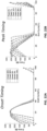
- different assistive profiles tracking can be realized, as shown in FIG. 22A, FIG. 22B , FIG. 22C and FIG. 22D .
- FIG. 22A, FIG. 22B , FIG. 22C and FIG. 22D show an example of force tracking on different assistive profiles when varying onset timing ( FIG. 22A ), peak timing ( FIG. 22B ), offset timing ( FIG. 22C ), and entire profile timing ( FIG. 22D ).
- the peak and offset timing actuation were selected as the control variables of the optimization.
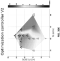
- FIG. 23A, FIG. 23B, and FIG. 23C show the landscape of different combination of control parameters of a representative subject.
- FIG. 23A Internal testing found that the combination of peak and offset timing can vary metabolics more than 20% ( FIG. 23A ) while other combinations seem to be already in an optimal range ( FIG. 23B) and FIG. 23C).
- FIG. 23B and FIG. 23C show that greatly reduced metabolics almost entire feasible region while FIG. 23A shows difference in metabolics depending on parameters.
- the algorithm selected the peak and offset timing variables within some predefined constraints:
- the magnitude of force and onset timing parameters were fixed.
- the magnitude of the peak force was selected to 30% of the subject's body weight for the subject's comfort while using the disclosed system.
- the maximum hip flexion point was picked as the onset timing of the assistive profile due to hip studies having shown a larger metabolic reduction with earlier onset timing.
- the example of candidate force profiles is shown in FIG. 24 .
- FIG. 24 shows an example of control variables (peak timing and offset timing) defining the assistive profile for each gait cycle.
- the onset timing is the detection of the maximum hip flexion for the current gait cycle and the magnitude of the peak force is 30% of the subject's body weight.
- Metabolic cost was computed directly in real-time using respiratory data.
- FIG. 25A, FIG. 25B , and FIG. 25C show the general process of the algorithm of an exemplary subject.
- This application may be particularly useful for persons with impaired gait requiring assistance during the swing phase and heel strike of gait (e.g., stroke, foot drop, MS).
- gait e.g., stroke, foot drop, MS.
- stroke patients may have reduced control of ankle dorsiflexion which results in a reduced capability to lift their foot during the swing phase, this presents difficulties to guarantee sufficient ground clearance and may result in patients catching their toe during walking which is a risk of tripping or developing compensatory strategies with the hip joint that impact their walking efficiency, stability and their overall musculoskeletal health.
- dorsiflexion assistance may help patients have a more controlled dorsiflexion speed after heel strike improving their overall walking dynamics.
- the wearable system may be configured to provide active assistance in dorsiflexion (unilateral).
- a suitable objective function may target typical biological landing angle at heel strike.
- Landing angle is an important feature of healthy walking, during walking on flat terrain, healthy individuals typically land with the heel (positive foot to floor angle). Some patient population such as stroke patients or patients with dorsiflexion deficits may land neutrally or with their toes (negative foot to floor angle) because they are not able to sufficiently dorsiflex their ankle during the swing phase ; this has implications on ground clearance and overall walking dynamics. Landing with a healthy-like ankle angle may improve walking efficiency and stability of patients.
- Foot to floor angle can be used to characterize whether patients land with their heel, neutrally or on their toes. Having a healthy-like or symmetric foot to floor angle may have implications on overall stability and walking efficiency. Patients are more likely to trip if their land with their toes as this may imply that they are not dorsiflexing enough during swing.
- the wearable system may include at least one sensor capable of measuring rotational angle and velocity of the paretic foot and at least one sensor capable of measuring rotational angle and velocity of the non-paretic foot by using sensors such as IMUs.
- the foot to floor angle may be calculated when detecting a strike of the foot with the ground (this timing event can be identified by for example looking at sudden changes in foot speed or acceleration when contacting the ground).
- this timing event can be identified by for example looking at sudden changes in foot speed or acceleration when contacting the ground.
- the peak foot to floor angle may be used as an objective function as described in the pseudocode above.
- Suitable actuation parameters to optimize may include one or a combination of: magnitude of cable travel during actuation, duration of maximum amplitude of actuation, onset timing of actuation, onset rate of actuation, offset timing of actuation, and release rate of actuation.
- the objective function is the landing angle (error_ftf_hs) which is minimized by modulating a dorsiflexion actuation magnitude (df_actuation_magnitude) within predefined boundaries (max_allowed_df_actuation_magnitude and min_allowed_df_actuation_magnitude), these boundaries have been defined so that the assistance doesn't go higher than our maximum actuation travel to guarantee comfort and safety, a lower limit on the assistance magnitude is defined as a safety parameter and can be defined by the user either as a threshold or on a patient-by-patient basis to guarantee that the users are getting a minimum amount of assistance to assist their walking.
- the actuation parameter is not perturbed any further if the landing error angle is within a threshold. This works as the termination strategy for the algorithm.
- the optimization approach may be configured to drive paretic FtF angle to an objective value determined empirically from literature or studies (e.g., approximately 20 degrees).
- the wearable system may be configured to provide active assistance in dorsiflexion (may be unilateral or bilateral), with at least one sensor capable of measuring rotational angle of the assisted foot (or two sensors if both feet are being assisted).
- the wearable system may be configured to provide active assistance in plantarflexion (unilateral).
- a suitable objective function may be maximizing gait symmetry between paretic and non-paretic limbs, non-symmetric walking is typically associated with low-walking efficiency and/or reduced stability.
- APGRF anterior-posterior ground reaction force
- the wearable system may include at least one sensor capable of measuring ground reaction forces such as the anterior-posterior ground reaction force, which is a measure of the reaction force on the ground from the user propelling themselves forward.
- ground reaction forces such as the anterior-posterior ground reaction force, which is a measure of the reaction force on the ground from the user propelling themselves forward.
- Alternative error measures can also be used.
- Suitable actuation parameters to optimize may include one or a combination of: magnitude of actuation, duration of maximum amplitude of actuation, onset timing of actuation, onset rate of actuation, offset timing of actuation, and release rate of actuation.
- Example #1 may be utilized to optimize forward propulsion in healthy persons in like manner by providing plantarflexion assistance.
- This application may be particularly useful for persons with impaired gait requiring assistance during the push-off phase of walking (e.g., stroke, MS).
- the wearable system may be configured to provide active assistance in plantarflexion, with sensors capable of measuring ankle speed and assistive force.
- a possible objective function proxy for estimating increased contribution of a joint to forward propulsion may be maximizing positive power delivered to the joint.
- Suitable actuation parameters to optimize may include one or a combination of: magnitude of actuation, duration of maximum amplitude of actuation, onset timing of actuation, onset rate of actuation, offset timing of actuation, and release rate of actuation.
- hip extension assistance This application may be particularly useful for persons with impaired hip function, which may result in walking deficits such as reduced forward propulsion. These patients may benefit from hip extension assistance.
- hip extension and trailing limb angle are contributors to forward propulsion and other important characteristics of gait.
- the hip, knee, and foot are positioned such that a line drawn between the 5th metatarsal of the foot and the greater trochanter of the hip will form an angle behind a vertical axis at the individual's center of mass. This angle is often referred to as the trailing limb angle.
- propulsion forces generated during plantar flexion will have an anterior-posterior vector to them, and will assist in propelling the body forward.
- a common result is a reduced or nonexistent trailing limb angle.
- the anterior-posterior vector of the propulsion forces generated during pushoff will be reduced, which can result in substantially reduced forward propulsion in these populations.
- Such individuals would be sensitive to changes in actuation parameters for hip extension, making hip extension assistance optimization particularly useful for this population.
- Hip assistance extension and flexion
- hip flexion assistance is also important around the time of push off as the wearer swings their leg forward. Different parameters would be use for hip flexion assistance.
- the wearable system may be configured to provide active assistance in hip extension (unilateral or bilateral).
- a suitable objective function may target typical biological trailing limb angle during terminal stance. This is the angle between the global vertical axis and the line defined by a point on the pelvis (often the greater trochanter or the hip joint center) and a point on the stance foot (often the fifth metatarsal head or the center of pressure).
- people with impaired gait may have a lower trailing limb angle during terminal stance.
- the controls approach could seek to minimize error between trailing limb angle at pushoff and an objective value determined empirically from literature or studies.
- the wearable system may include at least one sensor capable of measuring hip extension.
- the sensor or combination of sensors can be embodied by one or more inertial measurement units (IMUs) or alternative sensors capable of measuring, for example, thigh angular position, shank angular position, and foot angular position for the assisted limb.
- IMUs inertial measurement units
- thigh angular position we are able to calculate lower-limb kinematics, the orientation of the thigh, shank, and foot relative to one another. Incorporating all three orientations together allows us to approximate the trailing limb angle as described above.
- the thigh, shank, and foot angular position are also useful for detecting events during the gait cycle. For example the foot's angular position may allows the controller to determine when specific gait events occur, such as push-off and the foot's initial contact with the ground.
- Suitable actuation parameters to optimize may include one or a combination of: magnitude of actuation, duration of maximum amplitude of actuation, onset timing of actuation, onset rate of actuation, offset timing of actuation, and release rate of actuation.
- another embodiment for optimizing hip extension assistance may include a wearable system configured to provide active assistance in hip extension (unilateral), with at least one sensor capable of measuring trunk angular position, at least one sensor capable of measuring thigh angular position, and at least one sensor capable of measuring foot angular position for the assisted limb(s).
- a suitable objective function may target typical biological trailing limb angle at push-off, and as a proxy for the objective function, the controls approach could seek to minimize error between paretic hip extension angle at heel rise and non-paretic extension angle at heel strike from the previous step.
- Suitable actuation parameters to optimize may include one or a combination of: magnitude of actuation, duration of maximum amplitude of actuation, onset timing of actuation, onset rate of actuation, offset timing of actuation, and release rate of actuation.
- Characteristics of post-stroke hemiparetic gait can include impaired movement on the affected (paretic) side, which may include (among other things):
- the above unilateral deficits and weaknesses contribute to an asymmetric walking pattern with respect to the timing, spatial movements, and forces generated by each leg.
- the wearable system may be configured to provide active assistance to address one or more specific impairments in this population, for example by addressing point a) above by providing unilateral assistance to the wearer's affected limb during plantarflexion.
- a suitable objective function in this case may be maximizing the overall symmetry between each leg during respective portions of the gait cycle. The goal of perfect symmetry would indicate that both legs (paretic and non-paretic) are contributing equally to forward during walking, as is expected in healthy individuals.
- the wearable system may be configured to provide active assistance in plantarflexion (unilateral).
- a suitable objective function may be maximizing gait symmetry between paretic and non-paretic limbs
- the controls approach could seek to minimize error between paretic single-limb support time and the previous non-paretic single-limb support time (temporal symmetry).
- Temporal symmetry is an appropriate proxy for overall walking symmetry because a) both symmetries are influenced by the same deficits described above for this population, and b) temporal symmetry is accurate and feasible to measure with the available sensors in the system.
- the controls approach could seek to minimize error between paretic step time and the previous non-paretic step time (temporal symmetry).
- the wearable system may include at least one sensor capable of measuring rotational velocity of each foot. Using sensors to measure the rotational velocity of each foot, we can analyze these data to identify specific events in the gait cycle, such as paretic and non-paretic toe-off or heel strike. By detecting specific gait events we can divide the gait cycle into discrete phases for our optimization algorithms. For example, the paretic single -limb support time would be defined as the duration of time between the non-paretic toe-off event and the non-paretic heel strike event. When this is compared against the duration of the previous non-paretic single limb support, we can evaluate the difference (error) between these two values and incorporate this input into our optimization loop.
- Suitable actuation parameters to optimize may include one or a combination of: magnitude of actuation, duration of maximum amplitude of actuation, onset timing of actuation, onset rate of actuation, offset timing of actuation, and release rate of actuation.
- a controller can be applied to optimize objective functions that characterize the interaction between the suit and the wearer.
- an algorithm may optimize user self-reported comfort while walking on the exosuit.
- An embodiment may include a hand-held device as an input of the comfort of the wearer.
- the wearer may rate the comfort or perception of how assistive is the system with the current settings by pressing some button in the hand-held.
- An example rating will be (1-5) where 1 is much less assistive than the previous timing condition, 3 is as assistive as the previous condition and 5 is significantly more assistive than the previous condition.
- the parameters to be optimized could include the onset of the actuation, since, as explained previously, this parameter has a big impact in the individualization of the assistance.
- the system will vary the onset timing and wait for the user to provide input thought the device, based on the rating, the system would then move the onset parameter to a different value in the proximity using a method equivalent to the gradient descent method described above and modify the timing in the direction in which the user feels the system is more comfortable compared to the previous condition. It would also be possible to use pressure sensor data between the wearer and the device as a measure for comfort to the wearer. For example, if pressure was very high and localized that could be a measure of discomfort.
- a controller may have as an objective optimizing an objective function related to the performance of the device.
- an objective function related to the performance of the device.
- algorithm may be set-up to optimize the average positive power delivered to a biological joint during walking while minimizing the power consumption of the system.
- An example objective function will weight those two objectives based on priorities for the system.
- the weighting coefficients may be constant and defined by the system designer, variable defined by the user through a input device (hand-held remote, etc.) or varied automatically by the algorithm based on the conditions of the system, for instance the importance associated to battery consumption may be 0 when the system has full battery but 0.8 when the battery level is very low. For purposes of this example, the coefficients will be constant.
- An algorithm may optimize timing or magnitude variables such as the onset of the actuation to maximize the proposed objective function.
- the onset of actuation has an effect both on average positive power and on battery consumption which qualifies it as a suitable control parameter.
- Systems and methods of the present disclosure may include a control system architecture configured with an outer "optimization-related" loop consistent with the above-described optimization approaches, and an inner “reactive" loop for providing rapid controls adaptation in response to sudden changes (e.g., walking on uneven terrain, avoiding obstacles, or changing locomotive speed).
- the wearable system is free to dynamically react to sudden circumstances without being constrained by, or instead affecting, optimization efforts running over a longer period of time.
- control algorithm is divided in two loops:
- the following multi-dimensional optimization implementation has the goal of minimizing the metabolic cost of walking for different individuals. Measuring metabolic cost directly requires sensors that are intrusive and not suitable for every day wear, for instance, a mask to measure pulmonary gas exchange. However, for the ankle joint, maximizing the positive power delivered to the joint could be used as a proxy for the metabolic benefit; the more positive power that the system delivers to the joint, the more metabolic reduction the system will produce. This hypothesis has been confirmed during our protocols and other literatures as shown in FIG. 27A , FIG. 27B, and FIG. 27C .
- the selected optimization control variables for this study are characterized by the onset of the assistive profile (T1; when the cable starts to pull, which should be related to the start timing of push-off) and by the slope or duration of the assistance (D; how fast the cable pulls, which should be related to the ankle joint velocity during push-off).
- T1 onset of the assistive profile
- D slope or duration of the assistance
- the parameter space for these two variables may change between different subjects, different walking conditions (walking speed, step length, etc.), different systems (capabilities of the mechanics, stiffness of the suit-human interface, etc.), or by a combination of these.
- an algorithm that defines whether the current point in the search space is "feasible" or not has been implemented. Feasibility in this case is achieved when the system is able to deliver a force profile consistently between consecutive steps; if there is too much variability in the achieved peak force, the algorithm defines this as a failure point and won't consider this during the optimization.
- FIG. 29 An example of a point in the parameter space that is not-feasible is shown in FIG. 29 .
- the point does not result in consistent force delivery.
- the peak assistive force significantly drops from the desired value (400N), even while a same motor profile is applied. Therefore the algorithm does not consider this point as part of the search space.
- Another condition that could be added to constrain available parameter space is maximum electrical power consumption for each condition, therefore, the algorithm would only consider points that consume less electrical power than a defined threshold; this could be of interest when the system has to be able to assist during a long distance to make sure that the battery will last.
- the multi-level, multi-parameter alternating optimization searches the best value for the two parameters (T1,D) in rotation and reduces the step width as the search advances to improve granularity of the optimization.
- FIG. 30A, FIG. 30B , FIG. 30C, FIG. 30D , and FIG. 30E show an example of how the optimization works between different steps while a subject is walking on a treadmill at a speed of 1.5m/sec.
- This algorithm shows that the delivered power can be increased from 8.0 W to 12.5W by optimizing the onset and duration of the actuation; this increase is very significant and greatly improves the performance of the system.
- the following figure also shows how the algorithm is able to dynamically define the feasible search space by discarding points in which the force cannot be delivered consistently; the conditions labeled as "failed" and the blue area in the following graph are the search space that is not achievable for this subject and walking condition.
- FIG. 31 summarizes the results when testing this algorithm on 6 subjects walking at 1.5 m/sec comparing two different algorithm, an algorithm that uses the same timing for every individual and an optimization algorithm that maximizes delivered positive power to the ankle joint.
- This demonstrates that i) the positive ankle power is increased for every subject by using this optimization approach, ii) that as a consequence, the metabolic benefit of the subjects measured by wearing a COSMED gas exchange measurement system is also improved.
- This also shows that the selection of positive power as a proxy is valid and iii) that the optimal timings are different for each subject which highlights the need for optimization.
- FIG. 32 shows that the assistive profile is different between optimal and original timing conditions and the power plot clearly shows that the optimal profile is able to deliver significantly more positive power to the ankle joint.
- the graph on the right shows that between using a controller with constant timings vs. adapting the timing using an optimization algorithm, every subject was able to improve metabolic reduction going from a reduction of 11.97% for constant timing to a reduction of 18.8% with optimization in average; this difference is extremely promising.
- FIG. 33A, FIG. 33B , FIG. 33C, FIG. 33D , and FIG. 33E show an example of how this algorithm would work. These graphs were created in real-time on a subject walking on a treadmill. As shown in the next figure, the algorithm will exclude conditions that consume too much power. As shown in the last graph, the algorithm selected a condition that produces 7.74 W of positive power as opposed to the global optimum which would have been 7.59 W but it does so consuming electrical power below the specified threshold during these tests.
- Another embodiment of this optimization procedure would be running continuously during walking and adapt to any changes in gait by optimizing the objective function as the user walks or as the user does the desired activity.
Landscapes
- Engineering & Computer Science (AREA)
- Robotics (AREA)
- Mechanical Engineering (AREA)
- Physics & Mathematics (AREA)
- General Physics & Mathematics (AREA)
- Automation & Control Theory (AREA)
- Rehabilitation Tools (AREA)
- Manipulator (AREA)
Claims (14)
- Système portable comprenant :une combinaison robotique ou un exosquelette configuré pour couvrir une ou plusieurs articulations d'un utilisateur ;au moins un actionneur configuré pour générer une force dans la combinaison robotique ou l'exosquelette ;au moins deux capteurs configurés pour mesurer des informations permettant d'évaluer une fonction objective associée à au moins l'une de la fourniture d'une assistance physique au porteur, d'une interaction entre le porteur et la combinaison robotique ou l'exosquelette, et d'une action de la combinaison robotique ou de l'exosquelette ; etau moins un dispositif de commande configuré pour :actionner ledit au moins un actionneur selon au moins un profil d'actionnement,évaluer la fonction objective sur la base des informations mesurées par lesdits au moins deux capteurs afin de déterminer un changement résultant de la fonction objective,ajuster au moins un paramètre dudit au moins un profil d'actionnement sur la base du changement résultant de la fonction objective, etpoursuivre l'actionnement, l'évaluation et l'ajustement pour optimiser ledit au moins un paramètre d'actionnement afin d'augmenter au maximum la fonction objective,dans lequel lesdits au moins deux capteurs sont configurés pour mesurer une vitesse de rotation d'une articulation du porteur et une force générée dans la combinaison robotique ou l'exosquelette, etdans lequel ledit au moins un dispositif de commande est configuré pour calculer, sur la base des mesures provenant desdits au moins deux capteurs, une puissance positive moyenne délivrée par la combinaison robotique ou l'exosquelette au porteur, et dans lequel la fonction objective est la puissance positive moyenne.
- Système portable selon la revendication 1,
dans lequel ledit au moins un paramètre dudit au moins un profil d'actionnement est sélectionné dans le groupe comprenant : un moment de déclenchement de l'actionnement, un moment de décalage de l'actionnement, une vitesse d'actionnement, un moment auquel une amplitude maximale d'actionnement est atteinte, une amplitude maximale d'actionnement, une amplitude minimale d'actionnement, et une forme globale du profil d'actionnement. - Système portable selon l'une quelconque des revendications précédentes,
dans lequel ledit au moins un dispositif de commande est configuré pour optimiser ledit au moins un paramètre d'actionnement jusqu'à ce que la fonction objective atteigne une valeur maximale, ou jusqu'à ce qu'un critère de terminaison prédéfini soit satisfait. - Système portable selon la revendication 3,
dans lequel le critère de terminaison prédéfini est sélectionné dans le groupe comprenant les éléments suivants : (i) une différence entre des évaluations de la fonction objective pour des ajustements successifs dudit au moins un paramètre dudit au moins un profil d'actionnement s'abaisse en dessous d'un seuil prédéterminé, (ii) une différence entre des ajustements successifs dudit au moins un paramètre dudit au moins un profil d'actionnement s'abaisse en dessous d'un seuil prédéterminé, (iii) une durée prédéfinie depuis le début de l'optimisation a été dépassée, (iv) le porteur dépasse un nombre prédéfini de pas depuis le début de l'optimisation, et (v) une commande de terminaison est émise par le porteur. - Système portable selon l'une quelconque des revendications précédentes,
dans lequel le dispositif de commande est configuré pour utiliser un processus de descente de gradient lors de l'actionnement, de l'évaluation et de l'ajustement afin d'optimiser ledit au moins un paramètre d'actionnement pour augmenter au maximum la fonction objective. - Système portable selon l'une quelconque des revendications précédentes,dans lequel, lors de l'évaluation de la fonction objective, le dispositif de commande est configuré pour déterminer si l'évaluation a augmenté ou diminué par rapport à un ou à une moyenne d'évaluations précédentes de la fonction objective, etdans lequel, lors de l'ajustement dudit au moins un paramètre dudit au moins un profil d'actionnement, le dispositif de commande est configuré pour poursuivre l'ajustement dudit au moins un paramètre dans la même direction si la fonction objective a augmenté par rapport à un ou à une moyenne d'évaluations précédentes, et pour ajuster ledit au moins un paramètre dans une direction opposée si la fonction objective a diminué par rapport à un ou à une moyenne d'évaluations précédentes.
- Système portable selon l'une quelconque des revendications précédentes,dans lequel l'étape d'actionnement comprend l'actionnement dudit au moins un actionneur selon un premier ensemble de profils d'actionnement pendant une période correspondante, le premier ensemble de profils d'actionnement présentant des variations d'une valeur d'au moins un paramètre d'actionnement,dans lequel l'étape d'évaluation comprend une comparaison d'évaluations de la fonction objective acquises par lesdits au moins deux capteurs pendant chacune des périodes correspondantes afin de déterminer lequel des profils d'actionnement est associé à l'évaluation la plus élevée de la fonction objective, et dans lequel l'étape d'ajustement comprend la génération d'un second ensemble de profils d'actionnement avec des variations des valeurs dudit au moins un paramètre d'actionnement sur la base d'une dérivée de l'évaluation de la fonction objective associée au premier ensemble de profils d'actionnement.
- Système portable selon l'une quelconque des revendications précédentes,
dans lequel, au moins lors d'une itération initiale des étapes d'actionnement, d'évaluation et d'ajustement :l'étape d'actionnement comprend l'identification d'au moins un paramètre d'actionnement à optimiser pour augmenter au maximum la fonction objective, et l'actionnement dudit au moins un actionneur selon deux profils d'actionnement ou plus ayant des valeurs de référence différentes ou des ensembles de valeurs de référence différentes dudit au moins un paramètre d'actionnement à optimiser, etl'étape d'ajustement comprend la définition, sur la base d'évaluations correspondantes de la fonction objective provenant desdits au moins deux capteurs, d'une corrélation mathématique entre ledit au moins un paramètre d'actionnement et les évaluations correspondantes de la fonction objective, et l'évaluation de la corrélation mathématique de référence pour déterminer une valeur candidate ou un ensemble candidat de valeurs du ou des paramètre(s) d'actionnement pour augmenter au maximum la fonction objective ; et l'ajustement :
dans lequel, au moins lors d'une itération suivante des étapes d'actionnement, d'évaluation et d'ajustement :l'étape d'actionnement comprend l'actionnement dudit au moins un actionneur selon un profil d'actionnement associé à la valeur candidate ou à l'ensemble candidat de valeurs, etl'étape de mise à jour comprend la mise à jour de la corrélation mathématique sur la base d'une évaluation correspondante de la fonction objective provenant desdits au moins deux capteurs. - Système portable selon la revendication 8,dans lequel le dispositif de commande est configuré pour utiliser un processus Gaussien pour définir la corrélation mathématique, etdans lequel, lors de l'évaluation de la corrélation mathématique, le dispositif de commande est configuré pour utiliser un processus Bayésien pour déterminer la valeur candidate ou l'ensemble candidat de valeurs dudit au moins un paramètre d'actionnement.
- Système portable selon la revendication 8,dans lequel lesdites une ou plusieurs articulations du porteur comprennent une articulation de la hanche, etdans lequel ledit au moins un paramètre d'actionnement comprend un moment de pic d'actionnement et un moment de décalage de l'actionnement.
- Système portable selon l'une quelconque des revendications précédentes,dans lequel lesdits au moins deux capteurs sont configurés pour mesurer une force ou une pression entre un pied du porteur et une surface dans l'environnement physique du porteur, etdans lequel ledit au moins un dispositif de commande est configuré pour calculer, sur la base des mesures provenant desdits au moins deux capteurs, une force propulsive vers l'avant du porteur.
- Système portable selon l'une quelconque des revendications précédentes,dans lequel lesdits au moins deux capteurs sont configurés pour mesurer un angle de dorsiflexion de l'articulation de la cheville pendant la phase de balancement de la locomotion, etdans lequel ledit au moins un dispositif de commande est configuré pour calculer, sur la base des mesures provenant desdits au moins deux capteurs, une hauteur de dégagement du pied par rapport au sol pendant la phase de balancement de la locomotion.
- Système portable selon l'une quelconque des revendications précédentes,dans lequel lesdits au moins deux capteurs sont configurés pour mesurer un angle de contact au sol d'un pied parétique du porteur et un angle de contact au sol d'un pied non parétique du porteur, etdans lequel ledit au moins un dispositif de commande est configuré pour calculer, sur la base des mesures provenant desdits au moins deux capteurs, une différence entre l'angle de contact au sol du pied parétique et l'angle de contact au sol du pied non parétique.
- Système portable selon l'une quelconque des revendications précédentes, dans lequel lesdits au moins deux capteurs comprennent au moins une IMU.
Applications Claiming Priority (3)
| Application Number | Priority Date | Filing Date | Title |
|---|---|---|---|
| US201662365494P | 2016-07-22 | 2016-07-22 | |
| US201762522617P | 2017-06-20 | 2017-06-20 | |
| PCT/US2017/042286 WO2018017436A1 (fr) | 2016-07-22 | 2017-07-15 | Optimisation de commandes destiné à des systèmes portables |
Publications (3)
| Publication Number | Publication Date |
|---|---|
| EP3487666A1 EP3487666A1 (fr) | 2019-05-29 |
| EP3487666A4 EP3487666A4 (fr) | 2020-03-25 |
| EP3487666B1 true EP3487666B1 (fr) | 2024-11-13 |
Family
ID=60992540
Family Applications (1)
| Application Number | Title | Priority Date | Filing Date |
|---|---|---|---|
| EP17831613.9A Active EP3487666B1 (fr) | 2016-07-22 | 2017-07-15 | Optimisation de commandes destiné à des systèmes portables |
Country Status (4)
| Country | Link |
|---|---|
| US (1) | US11498203B2 (fr) |
| EP (1) | EP3487666B1 (fr) |
| CN (1) | CN109789543B (fr) |
| WO (1) | WO2018017436A1 (fr) |
Families Citing this family (58)
| Publication number | Priority date | Publication date | Assignee | Title |
|---|---|---|---|---|
| KR20150077413A (ko) | 2012-09-17 | 2015-07-07 | 프레지던트 앤드 펠로우즈 오브 하바드 칼리지 | 인간의 움직임에 대한 보조를 위한 소프트 엑소슈트 |
| US10843332B2 (en) | 2013-05-31 | 2020-11-24 | President And Fellow Of Harvard College | Soft exosuit for assistance with human motion |
| WO2015088863A2 (fr) | 2013-12-09 | 2015-06-18 | President And Fellows Of Harvard College | Combinaisons d'assistance flexibles, systèmes de combinaisons flexibles et procédés de fabrication et de commande de celles-ci pour une aide à la mobilité d'une personne |
| US10611020B2 (en) | 2013-12-19 | 2020-04-07 | Roam Robotics Inc. | Pneumatic exomuscle system and method |
| EP3102171A4 (fr) | 2014-02-05 | 2018-03-28 | President and Fellows of Harvard College | Systèmes, procédés et dispositifs d'aide à la marche pour des tout-petits présentant un retard de développement |
| US10864100B2 (en) | 2014-04-10 | 2020-12-15 | President And Fellows Of Harvard College | Orthopedic device including protruding members |
| CN106795868B (zh) | 2014-09-19 | 2020-05-12 | 哈佛大学校长及研究员协会 | 用于人类运动辅助的软外套 |
| US11590046B2 (en) | 2016-03-13 | 2023-02-28 | President And Fellows Of Harvard College | Flexible members for anchoring to the body |
| EP3487666B1 (fr) | 2016-07-22 | 2024-11-13 | President and Fellows of Harvard College | Optimisation de commandes destiné à des systèmes portables |
| US11259979B2 (en) | 2017-02-03 | 2022-03-01 | Roam Robotics Inc. | System and method for user intent recognition |
| WO2018170170A1 (fr) | 2017-03-14 | 2018-09-20 | President And Fellows Of Harvard College | Systèmes et procédés de fabrication de microstructures souples en 3d |
| CN109256189B (zh) * | 2018-09-19 | 2022-03-11 | 安徽大学 | 具有模型不确定性的下肢康复外骨骼的控制方法及系统 |
| US12076135B2 (en) | 2019-04-25 | 2024-09-03 | Arizona Board Of Regents On Behalf Of Arizona State University | Soft hip extension device to aid hemiparetic gait |
| CN110638449B (zh) * | 2019-09-30 | 2021-05-18 | 福州大学 | 一种基于机械功的肌肉量化分析方法 |
| US20220327777A1 (en) * | 2019-10-29 | 2022-10-13 | Accel Robotics Corporation | System that fits a parameterized three-dimensional shape to multiple two-dimensional images |
| EP4057950A4 (fr) | 2019-11-12 | 2023-10-18 | Dephy, Inc. | Exosquelette de membre inférieur |
| US11931307B2 (en) | 2019-12-13 | 2024-03-19 | Roam Robotics Inc. | Skiing exoskeleton control method and system |
| US11853034B2 (en) | 2020-05-08 | 2023-12-26 | Skip Innovations, Inc. | Exosuit activity transition control |
| JP7294232B2 (ja) * | 2020-05-15 | 2023-06-20 | トヨタ自動車株式会社 | メンテナンスシステム、メンテナンス方法、及びプログラム |
| US11334085B2 (en) * | 2020-05-22 | 2022-05-17 | The Regents Of The University Of California | Method to optimize robot motion planning using deep learning |
| EP4157198A4 (fr) | 2020-05-27 | 2024-06-26 | Roam Robotics Inc. | Systèmes et méthodes d'ajustement et de suspension pour un robot mobile |
| EP4157195A4 (fr) | 2020-05-27 | 2024-07-24 | Roam Robotics Inc. | Méthodes pour améliorer la mobilité d'un utilisateur et un traitement |
| US11298287B2 (en) | 2020-06-02 | 2022-04-12 | Dephy, Inc. | Systems and methods for a compressed controller for an active exoskeleton |
| US11148279B1 (en) * | 2020-06-04 | 2021-10-19 | Dephy, Inc. | Customized configuration for an exoskeleton controller |
| US11147733B1 (en) | 2020-06-04 | 2021-10-19 | Dephy, Inc. | Systems and methods for bilateral wireless communication |
| US11389367B2 (en) | 2020-06-05 | 2022-07-19 | Dephy, Inc. | Real-time feedback-based optimization of an exoskeleton |
| CN113063411A (zh) * | 2020-06-29 | 2021-07-02 | 河北工业大学 | 外骨骼评价系统及其使用方法 |
| US20220043940A1 (en) * | 2020-08-05 | 2022-02-10 | X Development Llc | 3d printed exosuit interface |
| US12090069B2 (en) | 2020-08-25 | 2024-09-17 | Dephy, Inc. | Systems and methods for a water resistant active exoskeleton |
| US11173093B1 (en) | 2020-09-16 | 2021-11-16 | Dephy, Inc. | Systems and methods for an active exoskeleton with local battery |
| CN112220650B (zh) * | 2020-12-09 | 2021-04-16 | 南京伟思医疗科技股份有限公司 | 一种外骨骼机器人对侧训练用在线步态生成控制系统 |
| CN112783043B (zh) * | 2020-12-30 | 2022-04-15 | 深圳市优必选科技股份有限公司 | 一种仿人机器人控制方法、装置、计算机设备及存储介质 |
| CN112932898B (zh) * | 2021-01-28 | 2022-09-30 | 东南大学 | 一种基于贝叶斯优化的按需辅助康复机器人 |
| CN113081671B (zh) * | 2021-03-31 | 2022-09-30 | 东南大学 | 一种基于贝叶斯优化提高按需辅助康复训练参与度的方法 |
| CN113103210B (zh) * | 2021-04-12 | 2022-09-09 | 合肥工业大学 | 基于per-ddqn的外骨骼助力可移动搬运系统控制方法 |
| CN115256339B (zh) * | 2021-04-29 | 2025-05-27 | 广州视源电子科技股份有限公司 | 穿戴设备的控制方法、装置及穿戴设备 |
| CN113442174B (zh) * | 2021-05-27 | 2023-05-02 | 重庆理工大学 | 外骨骼性能测试方法、装置及系统 |
| CN116916866A (zh) * | 2021-06-07 | 2023-10-20 | 三星电子株式会社 | 用于调整可穿戴装置的控制参数值的方法及装置 |
| CN113478465B (zh) * | 2021-07-23 | 2023-08-18 | 华南理工大学 | 动力外骨骼机器人输出力曲线的设计方法、装置、设备和介质 |
| USD1005361S1 (en) * | 2021-08-13 | 2023-11-21 | Festool Gmbh | Wearable robotic exoskeleton with belts |
| US20230333593A1 (en) * | 2021-08-16 | 2023-10-19 | Sanctuary Cognitive Systems Corporation | Inertial measurement units for teleoperation of robots |
| US12115663B2 (en) | 2021-08-17 | 2024-10-15 | Roam Robotics Inc. | Maritime applications for a mobile robot |
| US12466060B2 (en) | 2021-08-17 | 2025-11-11 | Roam Robotics Inc. | Mobile power source for a mobile robot |
| US12465543B2 (en) | 2021-10-12 | 2025-11-11 | Arizona Board Of Regents On Behalf Of Arizona State University | Passive exoskeleton for sit-to-stand and stand-to-sit transfer |
| EP4427889A4 (fr) * | 2021-12-08 | 2024-11-06 | Samsung Electronics Co., Ltd. | Procédé de détermination de valeur de paramètre pour commander un dispositif portable, et dispositif électronique pour l'exécution de ce procédé |
| CN114474012B (zh) * | 2021-12-15 | 2024-05-14 | 中国科学院深圳先进技术研究院 | 外骨骼机器人 |
| EP4454626A4 (fr) * | 2022-02-11 | 2025-03-26 | Samsung Electronics Co., Ltd | Procédé pour déterminer la valeur d'un paramètre de commande, et dispositif électronique pour mettre en ouvre ce procédé |
| CN114986508B (zh) * | 2022-06-13 | 2025-03-28 | 胜利油田胜机石油装备有限公司 | 一种修井装备机械臂路径规划方法 |
| EP4321772B1 (fr) | 2022-08-10 | 2025-02-19 | Able Human Motion, S.L. | Actionneur rétropilotable pour exosquelette |
| KR102778874B1 (ko) * | 2022-11-21 | 2025-03-11 | 한국전자통신연구원 | 엑소스켈레톤 제어로직 평가 방법 및 시스템 |
| CN115847488B (zh) * | 2023-02-07 | 2023-05-02 | 成都秦川物联网科技股份有限公司 | 用于协作机器人监测的工业物联网系统及控制方法 |
| CN115847427B (zh) | 2023-02-07 | 2024-07-16 | 成都秦川物联网科技股份有限公司 | 双重识别的协作机器人监测工业物联网系统及其控制方法 |
| CN116107193B (zh) * | 2023-02-14 | 2025-09-16 | 歌尔科技有限公司 | 智能穿戴设备 |
| JP7630750B1 (ja) * | 2023-06-13 | 2025-02-17 | 三菱電機株式会社 | 検査支援装置、検査支援システム、検査支援方法、及びプログラム |
| WO2025254728A1 (fr) * | 2024-06-06 | 2025-12-11 | Skip Innovations, Inc. | Exosquelette avec moteurs électromagnétiques à flux axial |
| CN119388430B (zh) * | 2024-11-22 | 2025-09-30 | 东南大学 | 一种基于非零和博弈的外肢体机器人辅助支撑控制方法 |
| CN119405302B (zh) * | 2024-11-22 | 2025-09-05 | 中国科学院沈阳自动化研究所 | 一种面向人体非平稳运动的外骨骼仿生助力曲线生成方法 |
| CN120392488B (zh) * | 2025-04-29 | 2026-04-14 | 南方科技大学 | 步态矫正系统 |
Family Cites Families (299)
| Publication number | Priority date | Publication date | Assignee | Title |
|---|---|---|---|---|
| US3387305A (en) | 1966-02-09 | 1968-06-11 | Rocky Mountain Sports | Knee protector |
| US3411511A (en) | 1966-11-04 | 1968-11-19 | Sears Roebuck & Co | Combined maternity support and garter belt |
| US3831467A (en) | 1973-03-16 | 1974-08-27 | R Moore | Knee brace |
| US4023215A (en) | 1976-02-17 | 1977-05-17 | Moore Robert R | Locking prosthetic knee |
| GB1586302A (en) | 1977-07-08 | 1981-03-18 | Kellie & Son Ltd Robert | Lockable hinge joint for limb supports and other orthopaedic appliances |
| US4252112A (en) | 1979-03-26 | 1981-02-24 | Joyce Raymond D | Strap device for assisting in hip, knee and foot movement |
| US4370977A (en) | 1981-05-04 | 1983-02-01 | Kenneth D. Driver | Knee and elbow brace |
| GB2149004B (en) | 1983-10-31 | 1986-07-16 | Hanger & Co Ltd J E | Electrically released prosthetic joint |
| US4724827A (en) | 1985-01-10 | 1988-02-16 | Schenck Robert R | Dynamic traction device |
| US4697808A (en) | 1985-05-16 | 1987-10-06 | Wright State University | Walking assistance system |
| GB8615269D0 (en) | 1986-06-23 | 1986-07-30 | Univ Strathclyde | Hybrid orthosis |
| US4682776A (en) | 1985-11-06 | 1987-07-28 | William Mitchell | User worn arm bend control device |
| US4760850A (en) | 1986-05-15 | 1988-08-02 | Wright State University | Method for balancing assistance |
| US5584799A (en) | 1989-09-11 | 1996-12-17 | Gray; James C. | Splint/therapeutic device |
| US5213094A (en) | 1990-07-30 | 1993-05-25 | Bonutti Peter M | Orthosis with joint distraction |
| US5020790A (en) | 1990-10-23 | 1991-06-04 | Board Of Supervisors Of Louisiana State University And Agricultural And Mechanical College | Powered gait orthosis |
| US5282460A (en) * | 1992-01-06 | 1994-02-01 | Joyce Ann Boldt | Three axis mechanical joint for a power assist device |
| RU2054907C1 (ru) | 1992-01-31 | 1996-02-27 | Акционерное Общество Закрытого Типа "Аюрведа" | Устройство для лечения больных с нарушением позы и двигательной активности |
| US20010007845A1 (en) | 1992-01-31 | 2001-07-12 | Afanasenko Nikolai Ivanovich | Device for treatment of patients with disturbed posture and motor activity |
| JP3530959B2 (ja) | 1993-12-13 | 2004-05-24 | 株式会社東京アールアンドデー | 平地歩行、階段歩行の電動補助装置 |
| US5485402A (en) | 1994-03-21 | 1996-01-16 | Prosthetics Research Study | Gait activity monitor |
| US5826578A (en) | 1994-05-26 | 1998-10-27 | Curchod; Donald B. | Motion measurement apparatus |
| US5667461A (en) | 1994-07-06 | 1997-09-16 | Hall; Raymond F. | Ambulatory traction assembly |
| US5599283A (en) | 1995-04-25 | 1997-02-04 | Lindenmeyer; Carl W. | Orthopedic appliance retainer |
| US5865770A (en) | 1995-12-06 | 1999-02-02 | Schectman; Leonard A. | Device to counteract paralysis |
| CA2218242C (fr) | 1996-10-11 | 2005-12-06 | Kenneth R. Fyfe | Systeme d'analyse de mouvement |
| US6812624B1 (en) | 1999-07-20 | 2004-11-02 | Sri International | Electroactive polymers |
| US6586859B2 (en) | 2000-04-05 | 2003-07-01 | Sri International | Electroactive polymer animated devices |
| US5865714A (en) | 1997-07-03 | 1999-02-02 | Marlowe; Dennis | Arm exercise device |
| US6123649A (en) | 1998-02-13 | 2000-09-26 | Lee; R. Clayton | Resistance apparatus for connection to a human body |
| US6872187B1 (en) | 1998-09-01 | 2005-03-29 | Izex Technologies, Inc. | Orthoses for joint rehabilitation |
| US6517503B1 (en) | 1998-09-18 | 2003-02-11 | Becker Orthopedic Appliance Company | Orthosis knee joint |
| US7410471B1 (en) | 1998-09-18 | 2008-08-12 | Becker Orthopedic Appliance Company | Orthosis knee joint and sensor |
| US6129691A (en) | 1999-03-24 | 2000-10-10 | Ruppert; John F. | Pliant back support apparatus with foot engagements |
| US6168634B1 (en) | 1999-03-25 | 2001-01-02 | Geoffrey W. Schmitz | Hydraulically energized magnetorheological replicant muscle tissue and a system and a method for using and controlling same |
| US7306672B2 (en) | 2001-04-06 | 2007-12-11 | California Institute Of Technology | Microfluidic free interface diffusion techniques |
| US6899137B2 (en) | 1999-06-28 | 2005-05-31 | California Institute Of Technology | Microfabricated elastomeric valve and pump systems |
| US7064472B2 (en) | 1999-07-20 | 2006-06-20 | Sri International | Electroactive polymer devices for moving fluid |
| DE60037433T2 (de) | 1999-07-20 | 2008-12-04 | Sri International, Menlo Park | Elektroaktive Polymergeneratoren |
| US6666831B1 (en) | 1999-08-20 | 2003-12-23 | The Regents Of The University Of California | Method, apparatus and system for automation of body weight support training (bwst) of biped locomotion over a treadmill using a programmable stepper device (psd) operating like an exoskeleton drive system from a fixed base |
| DE19944139A1 (de) | 1999-09-15 | 2001-04-05 | Walter Kuehnegger | Myotonische Behandlungsorthese |
| US6500138B1 (en) | 2000-04-07 | 2002-12-31 | Mayo Foundation For Medical Education And Research | Electromechanical joint control device with wrap spring clutch |
| TW475887B (en) | 2000-04-20 | 2002-02-11 | Wacoal Corp | Leg portions supporting wear |
| US6633783B1 (en) | 2000-06-06 | 2003-10-14 | Honda Giken Kogyo Kabushiki Kaisha | Fuzzy logic based control |
| US6689075B2 (en) | 2000-08-25 | 2004-02-10 | Healthsouth Corporation | Powered gait orthosis and method of utilizing same |
| US7918808B2 (en) | 2000-09-20 | 2011-04-05 | Simmons John C | Assistive clothing |
| US6741911B2 (en) | 2000-09-20 | 2004-05-25 | John Castle Simmons | Natural robot control |
| US6783555B2 (en) | 2000-10-27 | 2004-08-31 | Mark R. Kuhn | Gait orthosis |
| US20030009120A1 (en) | 2000-12-13 | 2003-01-09 | Macallister Doris | Device for prevention of abnormal joint rotation |
| US20040204294A2 (en) | 2000-12-29 | 2004-10-14 | William Wilkinson | Exercise device for exercising upper body simultaneously with lower body exercise |
| US7166953B2 (en) | 2001-03-02 | 2007-01-23 | Jon Heim | Electroactive polymer rotary clutch motors |
| JP2002301124A (ja) | 2001-04-06 | 2002-10-15 | Honda Motor Co Ltd | 歩行補助装置 |
| US6635024B2 (en) | 2001-05-14 | 2003-10-21 | Bobby Joe Hatton | Articulating knee supports |
| US7233097B2 (en) | 2001-05-22 | 2007-06-19 | Sri International | Rolled electroactive polymers |
| US7153242B2 (en) | 2001-05-24 | 2006-12-26 | Amit Goffer | Gait-locomotor apparatus |
| US7650204B2 (en) | 2001-06-29 | 2010-01-19 | Honda Motor Co., Ltd. | Active control of an ankle-foot orthosis |
| US7684896B2 (en) | 2001-06-29 | 2010-03-23 | Honda Motor Co., Ltd. | System and method of estimating joint loads using an approach of closed form dynamics |
| US7774177B2 (en) * | 2001-06-29 | 2010-08-10 | Honda Motor Co., Ltd. | Exoskeleton controller for a human-exoskeleton system |
| US7390309B2 (en) | 2002-09-23 | 2008-06-24 | Honda Motor Co., Ltd. | Human assist system using gravity compensation control system and method using multiple feasibility parameters |
| EP1418988A1 (fr) | 2001-08-22 | 2004-05-19 | The Regents of the University of California | Mecanisme de manipulation et de mesure du mouvement des jambes pendant la marche |
| EP1448273A2 (fr) | 2001-10-29 | 2004-08-25 | Igal Firsov | Dispositif orthetique personnalisable a support et application de forces reglables |
| JP4133216B2 (ja) * | 2001-10-29 | 2008-08-13 | 本田技研工業株式会社 | 人間補助装置のシミュレーション・システム、方法、およびコンピュータ・プログラム |
| US7153246B2 (en) | 2001-11-13 | 2006-12-26 | Richard Koscielny | Neurological motor therapy suit |
| SG103371A1 (en) | 2001-12-28 | 2004-04-29 | Matsushita Electric Works Ltd | Wearable human motion applicator |
| US6878122B2 (en) | 2002-01-29 | 2005-04-12 | Oregon Health & Science University | Method and device for rehabilitation of motor dysfunction |
| US20090030530A1 (en) | 2002-04-12 | 2009-01-29 | Martin James J | Electronically controlled prosthetic system |
| US20040064195A1 (en) | 2002-07-15 | 2004-04-01 | Hugh Herr | Variable-mechanical-impedance artificial legs |
| AU2003254887A1 (en) | 2002-08-09 | 2004-02-25 | Eamex Corporation | Process for producing conductive polymer |
| JP3930399B2 (ja) | 2002-08-21 | 2007-06-13 | 本田技研工業株式会社 | 歩行補助装置 |
| JP4808026B2 (ja) | 2002-08-22 | 2011-11-02 | ヴィクソム ヒューマン バイオニクス インコーポレーテッド | 膝上部肢切断患者用の駆動源付き義足 |
| US7736394B2 (en) * | 2002-08-22 | 2010-06-15 | Victhom Human Bionics Inc. | Actuated prosthesis for amputees |
| US6790165B2 (en) | 2002-09-03 | 2004-09-14 | Chih-Hung Huang | Rehabilitation aid |
| US7758481B2 (en) | 2002-09-04 | 2010-07-20 | Denis Burke Drennan | Dynamic hip stabilizer |
| US7476185B2 (en) | 2002-09-04 | 2009-01-13 | Denis Burke Drennan | Dynamic hip stabilizer |
| ATE417583T1 (de) | 2002-10-30 | 2009-01-15 | Helmut Wassermann | Aktive orthese |
| US6837830B2 (en) | 2002-11-01 | 2005-01-04 | Mark W. Eldridge | Apparatus using multi-directional resistance in exercise equipment |
| WO2004041914A1 (fr) | 2002-11-05 | 2004-05-21 | Eamex Corporation | Structure composite polymere conductrice |
| AU2003287705A1 (en) | 2002-11-05 | 2004-06-07 | Jingjiao Guan | Self-folding polymer microparticles |
| US7396337B2 (en) | 2002-11-21 | 2008-07-08 | Massachusetts Institute Of Technology | Powered orthotic device |
| US6966882B2 (en) | 2002-11-25 | 2005-11-22 | Tibion Corporation | Active muscle assistance device and method |
| US7090650B2 (en) | 2002-12-30 | 2006-08-15 | Industrial Technology Research Institute | Continuous passive motion exercise system with driven monitoring |
| US20040147378A1 (en) | 2003-01-29 | 2004-07-29 | Brad Conklin | Therapeutic device |
| DE10307328A1 (de) | 2003-02-17 | 2004-09-02 | Eska Implants Gmbh & Co. | Beinprothese |
| GB0307097D0 (en) | 2003-03-27 | 2003-04-30 | Bristol Myers Squibb Co | Compression device for the limb |
| WO2004099724A2 (fr) | 2003-05-06 | 2004-11-18 | Sri International | Systemes et procedes d'enregistrement des informations de position d'une tige de piston dans une couche magnetique sur une tige de piston |
| JP2005000500A (ja) | 2003-06-13 | 2005-01-06 | Yaskawa Electric Corp | 足関節電動装具 |
| US10286279B2 (en) | 2003-07-16 | 2019-05-14 | Vertimax, Llc | Lateral training system and method |
| JP4178186B2 (ja) | 2003-08-21 | 2008-11-12 | 国立大学法人 筑波大学 | 装着式動作補助装置、装着式動作補助装置の制御方法および制御用プログラム |
| EP1751843B1 (fr) | 2003-08-29 | 2012-09-19 | SRI International | Precontrainte d'un polymere electroactif |
| DK1665880T3 (da) | 2003-09-03 | 2013-02-25 | Stanford Res Inst Int | Elektroaktive overfladedeformations- polymertransducere |
| CN1303582C (zh) | 2003-09-09 | 2007-03-07 | 摩托罗拉公司 | 自动语音归类方法 |
| WO2005025464A2 (fr) | 2003-09-11 | 2005-03-24 | The Cleveland Clinic Foundation | Appareil d'assistance au deplacement |
| US8075633B2 (en) | 2003-09-25 | 2011-12-13 | Massachusetts Institute Of Technology | Active ankle foot orthosis |
| US7331906B2 (en) | 2003-10-22 | 2008-02-19 | Arizona Board Of Regents | Apparatus and method for repetitive motion therapy |
| US7341295B1 (en) | 2004-01-14 | 2008-03-11 | Ada Technologies, Inc. | Prehensor device and improvements of same |
| US7355519B2 (en) | 2004-02-24 | 2008-04-08 | Kevin Grold | Body force alarming apparatus and method |
| JP4200492B2 (ja) | 2004-03-11 | 2008-12-24 | 国立大学法人 筑波大学 | 装着式動作補助装置 |
| EP1737564B1 (fr) | 2004-03-12 | 2019-09-11 | SRI International | Meta-materiaux mecaniques |
| DE102004020368B4 (de) | 2004-04-23 | 2014-03-06 | Otto Bock Healthcare Gmbh | Künstlicher gelenkloser Fuß |
| IL161687A (en) | 2004-04-29 | 2010-06-16 | Igal Firsov | Orthotic bracing device |
| US7494450B2 (en) | 2004-05-14 | 2009-02-24 | Solomon Richard D | Variable unweighting and resistance training and stretching apparatus for use with a cardiovascular or other exercise device |
| US7544172B2 (en) | 2004-06-29 | 2009-06-09 | Rehabilitation Institute Of Chicago Enterprises | Walking and balance exercise device |
| US7645246B2 (en) | 2004-08-11 | 2010-01-12 | Omnitek Partners Llc | Method for generating power across a joint of the body during a locomotion cycle |
| US7445606B2 (en) | 2004-08-11 | 2008-11-04 | Omnitek Partners Llc | Methods and devices for selective exercising of muscles |
| US8938289B2 (en) | 2004-08-25 | 2015-01-20 | Motorika Limited | Motor training with brain plasticity |
| US20070004571A1 (en) | 2004-09-09 | 2007-01-04 | Rafael Gonzalez | Joint alignment and compression assembly and method for performing a rehabilitative treatment regimen |
| US7429253B2 (en) | 2004-09-21 | 2008-09-30 | Honda Motor Co., Ltd. | Walking assistance system |
| WO2006039403A1 (fr) | 2004-09-29 | 2006-04-13 | Northwestern University | Systeme et methodes pour surmonter un dysfonctionnement induit par gravite dans des cas extremes de paresie |
| US20060108755A1 (en) | 2004-10-01 | 2006-05-25 | Robert Smyler | High performance three-wheeled skates |
| US7775999B2 (en) | 2004-10-01 | 2010-08-17 | Randall Brown | Apparatus and method for use of a hip brace |
| WO2006052954A2 (fr) | 2004-11-09 | 2006-05-18 | Northeastern University | Frein et dispositifs actionneurs a fluide electrorheologique et dispositifs orthetiques equipes desdits frein et dispositifs actionneurs |
| JP4322785B2 (ja) | 2004-11-24 | 2009-09-02 | 株式会社東芝 | 音声認識装置、音声認識方法および音声認識プログラム |
| JP4541867B2 (ja) | 2004-12-16 | 2010-09-08 | 本田技研工業株式会社 | 外力制御方法、外力制御システム及び外力制御プログラム |
| EP1845849B1 (fr) | 2005-01-18 | 2019-04-10 | The Regents of The University of California | Exosquelette des membres inferieurs |
| JP4582523B2 (ja) | 2005-01-24 | 2010-11-17 | 政則 愛知 | 四肢矯正具 |
| JP4178187B2 (ja) | 2005-01-26 | 2008-11-12 | 国立大学法人 筑波大学 | 装着式動作補助装置及び制御用プログラム |
| US8048007B2 (en) | 2005-02-02 | 2011-11-01 | össur hf | Prosthetic and orthotic systems usable for rehabilitation |
| US9616274B2 (en) | 2005-03-01 | 2017-04-11 | Michael A. Wehrell | Swing training apparatus and method |
| US7595580B2 (en) | 2005-03-21 | 2009-09-29 | Artificial Muscle, Inc. | Electroactive polymer actuated devices |
| US7626319B2 (en) | 2005-03-21 | 2009-12-01 | Artificial Muscle, Inc. | Three-dimensional electroactive polymer actuated devices |
| US7521840B2 (en) | 2005-03-21 | 2009-04-21 | Artificial Muscle, Inc. | High-performance electroactive polymer transducers |
| US7521847B2 (en) | 2005-03-21 | 2009-04-21 | Artificial Muscle, Inc. | High-performance electroactive polymer transducers |
| US7750532B2 (en) | 2005-03-21 | 2010-07-06 | Artificial Muscle, Inc. | Electroactive polymer actuated motors |
| US8512415B2 (en) | 2005-03-31 | 2013-08-20 | Massachusetts Institute Of Technology | Powered ankle-foot prothesis |
| US20070123997A1 (en) | 2005-03-31 | 2007-05-31 | Massachusetts Institute Of Technology | Exoskeletons for running and walking |
| US20060249315A1 (en) | 2005-03-31 | 2006-11-09 | Massachusetts Institute Of Technology | Artificial human limbs and joints employing actuators, springs, and variable-damper elements |
| US10080672B2 (en) * | 2005-03-31 | 2018-09-25 | Bionx Medical Technologies, Inc. | Hybrid terrain-adaptive lower-extremity systems |
| US7313463B2 (en) | 2005-03-31 | 2007-12-25 | Massachusetts Institute Of Technology | Biomimetic motion and balance controllers for use in prosthetics, orthotics and robotics |
| US8500823B2 (en) | 2005-03-31 | 2013-08-06 | Massachusetts Institute Of Technology | Powered artificial knee with agonist-antagonist actuation |
| US7998040B2 (en) | 2005-04-11 | 2011-08-16 | The Regents Of The University Of Colorado | Force assistance device for walking rehabilitation therapy |
| US7259553B2 (en) | 2005-04-13 | 2007-08-21 | Sri International | System and method of magnetically sensing position of a moving component |
| EP1874239B1 (fr) | 2005-04-13 | 2014-06-11 | The Regents of The University of California | Exosquelette des membres inferieurs semi-motorise |
| EP2168548B1 (fr) | 2005-05-27 | 2016-10-19 | Honda Motor Co., Ltd. | Dispositif d'assistance à la marche |
| CN1868434B (zh) | 2005-05-27 | 2011-12-28 | 本田技研工业株式会社 | 行走辅助装置的控制装置 |
| JP4424269B2 (ja) | 2005-06-24 | 2010-03-03 | カシオ計算機株式会社 | 筋力制御装置 |
| US20090042702A1 (en) | 2005-08-02 | 2009-02-12 | Brian Toronto | Proprioception enhancement system |
| US8299634B2 (en) | 2005-08-10 | 2012-10-30 | Bionic Power Inc. | Methods and apparatus for harvesting biomechanical energy |
| US20070135279A1 (en) | 2005-12-14 | 2007-06-14 | Peter Purdy | Resistance garments |
| US8083644B2 (en) | 2005-12-14 | 2011-12-27 | Peter Purdy | Resistance garments and active materials |
| US8467904B2 (en) | 2005-12-22 | 2013-06-18 | Honda Motor Co., Ltd. | Reconstruction, retargetting, tracking, and estimation of pose of articulated systems |
| WO2007079777A1 (fr) | 2006-01-13 | 2007-07-19 | Smm Medical Ab | Appareil, système et méthode pour traitement compressif d'une partie du corps |
| US7190141B1 (en) | 2006-01-27 | 2007-03-13 | Villanova University | Exoskeletal device for rehabilitation |
| US7827000B2 (en) | 2006-03-03 | 2010-11-02 | Garmin Switzerland Gmbh | Method and apparatus for estimating a motion parameter |
| US7883546B2 (en) | 2006-03-09 | 2011-02-08 | The Regents Of The University Of California | Power generating leg |
| US20080009771A1 (en) | 2006-03-29 | 2008-01-10 | Joel Perry | Exoskeleton |
| WO2007120819A2 (fr) | 2006-04-15 | 2007-10-25 | The Board Of Regents Of The Leland Stanford Junior University | Systemes et procedes pour estimer une electromyographie de surface |
| US20070250179A1 (en) | 2006-04-19 | 2007-10-25 | Latour Debra A | Anchoring system for prosthetic and orthotic devices |
| US7558622B2 (en) | 2006-05-24 | 2009-07-07 | Bao Tran | Mesh network stroke monitoring appliance |
| US7556606B2 (en) | 2006-05-18 | 2009-07-07 | Massachusetts Institute Of Technology | Pelvis interface |
| US20080000317A1 (en) | 2006-05-31 | 2008-01-03 | Northwestern University | Cable driven joint actuator and method |
| US7551419B2 (en) | 2006-06-05 | 2009-06-23 | Sri International | Electroadhesion |
| US7578799B2 (en) | 2006-06-30 | 2009-08-25 | Ossur Hf | Intelligent orthosis |
| US8246559B2 (en) | 2006-09-01 | 2012-08-21 | Worcester Polytechnic Institute | Two degree of freedom powered orthosis |
| US20080062589A1 (en) | 2006-09-08 | 2008-03-13 | Artificial Muscle, Inc. | High-voltage power supplies |
| US8110254B1 (en) | 2006-09-12 | 2012-02-07 | Sri International | Flexible circuit chemistry |
| JP4345025B2 (ja) | 2006-09-12 | 2009-10-14 | 国立大学法人 北海道大学 | 筋力補助装置 |
| US7981508B1 (en) | 2006-09-12 | 2011-07-19 | Sri International | Flexible circuits |
| JP5557529B2 (ja) | 2006-09-19 | 2014-07-23 | マイオモ インコーポレイテッド | 動力で作動する矯正デバイス |
| US8585620B2 (en) | 2006-09-19 | 2013-11-19 | Myomo, Inc. | Powered orthotic device and method of using same |
| US8597369B2 (en) | 2006-10-17 | 2013-12-03 | Northwestern University | Equilibrium-point prosthetic and orthotic ankle-foot systems and devices |
| US8376974B2 (en) | 2006-11-03 | 2013-02-19 | Richard A. Nace | Knee orthosis swing assist mechanism |
| JP4848260B2 (ja) | 2006-12-12 | 2011-12-28 | ピジョン株式会社 | 妊婦帯 |
| US8248750B2 (en) | 2007-12-13 | 2012-08-21 | Bayer Materialscience Ag | Electroactive polymer transducers |
| JP5896591B2 (ja) | 2006-12-14 | 2016-03-30 | パーカー ハネフィン コーポレイションParker Hannifin Corporation | 容量性構造体、その製造方法およびその作動方法ならびに容量性構造体を備えたシステム |
| US7492076B2 (en) | 2006-12-29 | 2009-02-17 | Artificial Muscle, Inc. | Electroactive polymer transducers biased for increased output |
| US7977923B2 (en) | 2007-03-09 | 2011-07-12 | Sri International | Circuits for electroactive polymer generators |
| US7804227B2 (en) | 2007-03-16 | 2010-09-28 | Sri International | Tear resistant electroactive polymer transducers |
| WO2008124025A1 (fr) | 2007-04-06 | 2008-10-16 | University Of Delaware | Orthèse électrique |
| US7897168B2 (en) | 2007-04-13 | 2011-03-01 | Medtronic Vascular, Inc. | Degradable polymers incorporating gamma-butyrolactone |
| US7884727B2 (en) | 2007-05-24 | 2011-02-08 | Bao Tran | Wireless occupancy and day-light sensing |
| US8058861B2 (en) | 2007-06-05 | 2011-11-15 | Bayer Materialscience Ag | Miniature high-voltage power supplies |
| FR2917323B1 (fr) | 2007-06-12 | 2009-10-02 | Commissariat Energie Atomique | Mecanisme de rotation d'avant-bras et orthese comportant un tel mecanisme |
| JP5122188B2 (ja) | 2007-06-27 | 2013-01-16 | 学校法人 久留米大学 | 電気的筋肉刺激用着用具 |
| JP5602626B2 (ja) | 2007-06-29 | 2014-10-08 | アーティフィシャル マッスル,インク. | 感覚性フィードバック用途のための電気活性ポリマートランスデューサー |
| EP2180920A1 (fr) | 2007-07-20 | 2010-05-05 | Össur HF | Dispositif prothétique ou orthopédique ayant une rétroaction |
| US8388519B2 (en) | 2007-07-26 | 2013-03-05 | Sri International | Controllable dexterous endoscopic device |
| DE102008053566A1 (de) | 2007-11-27 | 2009-06-04 | Bernhard Hildebrandt | System aus Endprothesen und Geräten zur minimal invasiven und zementfreien Implantation von Endoprothesen der Schulter und der Hüfte und der Offset-Verbesserung des Schenkelhalses |
| KR20100094998A (ko) | 2007-12-27 | 2010-08-27 | 고쿠리쯔 다이가쿠 호징 츠쿠바 다이가쿠 | 중심위치 검출장치 및 중심위치 검출장치를 구비한 장착식 동작보조장치 |
| US20090255531A1 (en) | 2008-01-07 | 2009-10-15 | Johnson Douglas E | Portable system for assisting body movement |
| EP2247998B1 (fr) | 2008-02-28 | 2019-04-10 | New York University | Procédé et appareil permettant de fournir des données à un processeur, et bloc capteur |
| EP2326288B1 (fr) | 2008-05-20 | 2016-04-20 | Ekso Bionics, Inc. | Dispositif et procédé pour diminuer une consommation énergétique d'une personne utilisant un exosquelette d'extrémités inférieures |
| US20090306548A1 (en) | 2008-06-05 | 2009-12-10 | Bhugra Kern S | Therapeutic method and device for rehabilitation |
| CN102098986B (zh) | 2008-07-23 | 2015-09-09 | 伯克利仿生技术公司 | 外骨骼和控制该外骨骼的迈步腿的方法 |
| US8764850B2 (en) | 2008-07-31 | 2014-07-01 | Northwestern University | Bi-modal ankle-foot device |
| JP5147595B2 (ja) | 2008-08-08 | 2013-02-20 | 本田技研工業株式会社 | 歩行補助装置の制御装置および制御方法 |
| US8274244B2 (en) | 2008-08-14 | 2012-09-25 | Tibion Corporation | Actuator system and method for extending a joint |
| JP5101469B2 (ja) | 2008-08-25 | 2012-12-19 | 本田技研工業株式会社 | アシスト装置 |
| JP2010051416A (ja) | 2008-08-27 | 2010-03-11 | Nabtesco Corp | 足関節の動作補助装置および足関節の動作補助装置の制御方法 |
| WO2010027968A2 (fr) * | 2008-09-04 | 2010-03-11 | Iwalk, Inc. | Systèmes hybrides à extrémités inférieures s’adaptant au terrain |
| US8409117B2 (en) | 2008-09-15 | 2013-04-02 | The Hong Kong Polytechnic University | Wearable device to assist with the movement of limbs |
| US9144528B2 (en) | 2008-09-26 | 2015-09-29 | The Trustees Of Columbia University In The City Of New York | Wearable cable-driven exoskeleton for functional arm training |
| US8096965B2 (en) | 2008-10-13 | 2012-01-17 | Argo Medical Technologies Ltd. | Locomotion assisting device and method |
| KR101043207B1 (ko) | 2008-10-22 | 2011-06-22 | 서강대학교산학협력단 | 휠체어식 보행 보조용 로봇 |
| US8222799B2 (en) | 2008-11-05 | 2012-07-17 | Bayer Materialscience Ag | Surface deformation electroactive polymer transducers |
| GB0820874D0 (en) | 2008-11-14 | 2008-12-24 | Europ Technology For Business | Assessment of gait |
| US7887471B2 (en) | 2008-11-25 | 2011-02-15 | Mcsorley Tyrone G | Neuromuscular training apparatus and method of use |
| JP4744589B2 (ja) | 2008-12-17 | 2011-08-10 | 本田技研工業株式会社 | 歩行補助装置及びその制御装置 |
| US20110313331A1 (en) | 2009-02-10 | 2011-12-22 | Bruno Marc Florent Victore Dehez | Rehabilitation Robot |
| GB0903534D0 (en) | 2009-03-03 | 2009-04-08 | Leicester Gordon C | Safety harness |
| CN102362308B (zh) | 2009-03-25 | 2014-04-09 | 索尼电脑娱乐公司 | 信息处理装置和信息处理方法 |
| EP2239793A1 (fr) | 2009-04-11 | 2010-10-13 | Bayer MaterialScience AG | Montage de film polymère électrique commutable et son utilisation |
| CA2759507A1 (fr) | 2009-04-28 | 2010-11-11 | Empowering Engineering Technologies Corp. | Prothese ajustable |
| US9017418B2 (en) | 2009-05-05 | 2015-04-28 | össur hf | Control systems and methods for prosthetic or orthotic devices |
| US8597222B2 (en) | 2009-06-12 | 2013-12-03 | Under Armour, Inc. | Garment with adjustable compression |
| CN102596133B (zh) | 2009-06-16 | 2017-04-12 | 奥托·博克保健有限公司 | 支撑绷带 |
| WO2010148134A1 (fr) | 2009-06-17 | 2010-12-23 | össur hf | Systèmes et procédés de commande à rétroaction pour dispositifs prothétiques ou orthétiques |
| US8438757B2 (en) | 2009-06-23 | 2013-05-14 | Mark Costin Roser | Human locomotion assisting shoe |
| WO2013033669A2 (fr) | 2011-09-01 | 2013-03-07 | President And Fellows Of Harvard College | Dispositifs orthétiques portables à commande active et manchon élastomère modulaire actif pour dispositifs orthétiques portables |
| WO2011008934A2 (fr) | 2009-07-15 | 2011-01-20 | President And Fellows Of Harvard College | Dispositifs orthotiques à commande active |
| EP2284933A1 (fr) | 2009-07-22 | 2011-02-16 | Bayer MaterialScience AG | Procédé de fabrication d'électrodes extensibles |
| JP5388747B2 (ja) | 2009-08-10 | 2014-01-15 | 本田技研工業株式会社 | トレーニング装置 |
| US8562691B2 (en) | 2009-08-10 | 2013-10-22 | Honda Motor Co., Ltd. | Training device |
| KR20120107928A (ko) | 2009-08-31 | 2012-10-04 | 아이워크, 아이엔씨. | 의족 보철 또는 지지대를 이용하는 기립 시퀀스의 구현 |
| WO2011026257A1 (fr) | 2009-09-03 | 2011-03-10 | Yang Changming | Système et procédé d'analyse de la démarche par des capteurs en tissu |
| WO2011030641A1 (fr) | 2009-09-08 | 2011-03-17 | コニカミノルタホールディングス株式会社 | Orthétique pour corps humain |
| US8443501B2 (en) | 2009-09-18 | 2013-05-21 | Joseph A. Mahon | Adjustable prosthetic interfaces and related systems and methods |
| WO2011033341A1 (fr) | 2009-09-21 | 2011-03-24 | Vrije Universiteit Brussel | Prothèse ou orthèse |
| US20110152696A1 (en) | 2009-12-22 | 2011-06-23 | Hall Ryan Laboratories, Inc. | Audible biofeedback heart rate monitor with virtual coach |
| US8325458B2 (en) | 2010-02-10 | 2012-12-04 | Sri International | Electroadhesive gripping |
| JP5105000B2 (ja) | 2010-03-17 | 2012-12-19 | トヨタ自動車株式会社 | 脚補助装置 |
| CN102892388A (zh) | 2010-04-05 | 2013-01-23 | Iwalk股份有限公司 | 控制假体或矫形器中的转矩 |
| WO2011139796A2 (fr) | 2010-04-27 | 2011-11-10 | The Johns Hopkins University | Structures sous-centimétriques auto-pliantes |
| US8608479B2 (en) | 2010-05-07 | 2013-12-17 | The University Of Kansas | Systems and methods for facilitating gait training |
| EP2400573A1 (fr) | 2010-06-23 | 2011-12-28 | Bayer MaterialScience AG | Convertisseur électromécanique, son procédé de fabrication et d'utilisation |
| US20130116611A1 (en) | 2010-07-28 | 2013-05-09 | Indaco S.R.L. | Support for human joints |
| WO2012050938A2 (fr) | 2010-09-29 | 2012-04-19 | President And Fellows Of Harvard College | Pavé de touches tactile vestimentaire avec peau artificielle étirable |
| US9480618B2 (en) | 2010-10-05 | 2016-11-01 | Elizabeth T. Hsiao-Wecksler | Portable active pneumatically powered ankle-foot orthosis |
| AU2011311954B2 (en) | 2010-10-06 | 2014-08-07 | Ekso Bionics | Human machine interfaces for lower extremity orthotics |
| GB2484463A (en) | 2010-10-11 | 2012-04-18 | Jonathan Butters | Apparatus to assist the rehabilitation of disabled persons |
| US8316719B2 (en) | 2010-11-12 | 2012-11-27 | President And Fellows Of Harvard College | Stretchable two-dimensional pressure sensor |
| DE202010015329U1 (de) | 2010-11-12 | 2011-02-24 | Harrer, Franz | Laufbandergometer mit adaptierten Zug- und Messeinheiten für therapeutische Anwendungen und zur Gangschule sowie Lauftraining |
| WO2012103073A2 (fr) | 2011-01-24 | 2012-08-02 | President And Fellows Of Harvard College | Détecteur de courbure élastomère sans mesure des différences de déformation |
| US8795411B2 (en) | 2011-02-07 | 2014-08-05 | Air Products And Chemicals, Inc. | Method for recovering high-value components from waste gas streams |
| CN103442607B (zh) | 2011-02-07 | 2016-06-22 | 新平衡运动公司 | 用于监视运动表现的系统和方法 |
| EP2497610B1 (fr) | 2011-03-09 | 2014-10-22 | Syco Di Hedvig Haberl & C. S.A.S. | Système pour contrôler un dispositif robotique pendant la marche, en particulier à des fins de rééducation et dispositif robotique correspondant |
| AU2012229920A1 (en) | 2011-03-14 | 2013-10-03 | Cadence Biomedical, Inc. | Orthosis |
| JP5868011B2 (ja) | 2011-03-16 | 2016-02-24 | 国立大学法人九州大学 | 歩行運動補助具 |
| US8784274B1 (en) | 2011-03-18 | 2014-07-22 | Thomas C. Chuang | Athletic performance monitoring with body synchronization analysis |
| US20120248942A1 (en) | 2011-04-01 | 2012-10-04 | Bayer Materialscience Ag | Electromechanical converter, method for its production and use thereof |
| US8460001B1 (en) | 2011-04-14 | 2013-06-11 | Thomas C. Chuang | Athletic performance monitoring with overstride detection |
| US9060884B2 (en) * | 2011-05-03 | 2015-06-23 | Victhom Human Bionics Inc. | Impedance simulating motion controller for orthotic and prosthetic applications |
| US8920517B2 (en) | 2011-05-04 | 2014-12-30 | The Cleveland Clinic Foundation | Modeling and desired control of an energy-storing prosthetic knee |
| WO2012175211A1 (fr) | 2011-06-21 | 2012-12-27 | Sabanci University | Exosquelette |
| US20140213951A1 (en) | 2011-06-24 | 2014-07-31 | Spaulding Rehabilitation Hospital Corporation | Robotic gait rehabilitation training system with orthopedic lower body exoskeleton for torque transfer to control rotation of pelvis during gait |
| US9545353B2 (en) | 2011-07-29 | 2017-01-17 | Leonis Medical Corporation | Methods of operating an exoskeleton for gait assistance and rehabilitation |
| US9072941B2 (en) | 2011-08-11 | 2015-07-07 | The Charles Stark Draper Laboratory, Inc. | Exoskeleton suit for adaptive resistance to movement |
| US20130079686A1 (en) | 2011-09-23 | 2013-03-28 | Blake Sessions | Apparatus, methods and systems to augment bipedal locomotion |
| KR102046377B1 (ko) | 2011-09-24 | 2019-11-19 | 프레지던트 앤드 펠로우즈 오브 하바드 칼리지 | 인공 피부 및 탄성 스트레인 센서 |
| WO2013049658A1 (fr) | 2011-09-28 | 2013-04-04 | Northeastern University | Exosquelette d'extrémité inférieure pour un perfectionnement de démarche |
| CN102327173B (zh) | 2011-09-29 | 2013-05-22 | 上海交通大学 | 外骨骼可穿戴下肢康复机器人 |
| US8847611B2 (en) | 2011-10-18 | 2014-09-30 | The Board Of Trustees Of The Leland Stanford Junior University | Capacitive differential quadrature rotary position sensor |
| US20130131555A1 (en) | 2011-11-17 | 2013-05-23 | William R. Hook | Gait analysis using angular rate reversal |
| CN202342034U (zh) | 2011-11-28 | 2012-07-25 | 西北工业大学 | 一种用于测量结构角度的光纤角度传感器 |
| US20130165817A1 (en) | 2011-12-09 | 2013-06-27 | Robert W. Horst | Orthotic device sensor |
| US9498401B2 (en) * | 2011-12-20 | 2016-11-22 | Massachusetts Institute Of Technology | Robotic system for simulating a wearable device and method of use |
| JP5821639B2 (ja) | 2012-01-05 | 2015-11-24 | 株式会社デンソー | 音声認識装置 |
| JP2013146328A (ja) | 2012-01-18 | 2013-08-01 | Seiko Epson Corp | 動作支援装置 |
| US20130186699A1 (en) | 2012-01-23 | 2013-07-25 | Sri International | High voltage converters for electrostatic applications |
| US9682005B2 (en) | 2012-02-24 | 2017-06-20 | Massachusetts Institute Of Technology | Elastic element exoskeleton and method of using same |
| US20130253385A1 (en) | 2012-03-21 | 2013-09-26 | Amit Goffer | Motorized exoskeleton unit |
| JPWO2013146231A1 (ja) | 2012-03-29 | 2015-12-10 | 住友理工株式会社 | 変形センサ |
| US9044346B2 (en) | 2012-03-29 | 2015-06-02 | össur hf | Powered prosthetic hip joint |
| JP5876358B2 (ja) | 2012-03-30 | 2016-03-02 | 国立大学法人九州大学 | 歩行運動補助具 |
| US9195794B2 (en) | 2012-04-10 | 2015-11-24 | Honda Motor Co., Ltd. | Real time posture and movement prediction in execution of operational tasks |
| US9221177B2 (en) * | 2012-04-18 | 2015-12-29 | Massachusetts Institute Of Technology | Neuromuscular model-based sensing and control paradigm for a robotic leg |
| CA2876206A1 (fr) | 2012-06-15 | 2013-12-19 | Vanderbilt University | Dispositif d'assistance au deplacement |
| JP5986445B2 (ja) | 2012-07-20 | 2016-09-06 | 国立大学法人九州大学 | 歩行用遊脚振子運動補助具およびアシスト力の制御方法 |
| JPWO2014034145A1 (ja) | 2012-08-30 | 2016-08-08 | 株式会社ニコン | 補助用具 |
| KR20150077413A (ko) * | 2012-09-17 | 2015-07-07 | 프레지던트 앤드 펠로우즈 오브 하바드 칼리지 | 인간의 움직임에 대한 보조를 위한 소프트 엑소슈트 |
| US9230560B2 (en) | 2012-10-08 | 2016-01-05 | Nant Holdings Ip, Llc | Smart home automation systems and methods |
| US9956687B2 (en) * | 2013-03-04 | 2018-05-01 | Microsoft Technology Licensing, Llc | Adapting robot behavior based upon human-robot interaction |
| CN206123638U (zh) | 2013-03-15 | 2017-04-26 | Sri国际公司 | 人体增强系统 |
| US10843332B2 (en) | 2013-05-31 | 2020-11-24 | President And Fellow Of Harvard College | Soft exosuit for assistance with human motion |
| KR20140142463A (ko) | 2013-06-04 | 2014-12-12 | 한국전자통신연구원 | 보행 모니터링 장치 및 방법 |
| US10285625B2 (en) | 2013-10-07 | 2019-05-14 | Wahoo Fitness Llc | Activity monitoring computing device and system |
| KR101895140B1 (ko) | 2013-11-18 | 2018-09-04 | 보아 테크놀러지, 인크. | 보철 및 장구의 자동 폐쇄를 제공하기 위한 방법 및 장치 |
| WO2015088863A2 (fr) | 2013-12-09 | 2015-06-18 | President And Fellows Of Harvard College | Combinaisons d'assistance flexibles, systèmes de combinaisons flexibles et procédés de fabrication et de commande de celles-ci pour une aide à la mobilité d'une personne |
| US9292786B2 (en) * | 2014-02-03 | 2016-03-22 | Disney Enterprises, Inc. | Universal balancing controller for lateral stabilization of bipedal robots in dynamic unstable environments |
| EP3102171A4 (fr) | 2014-02-05 | 2018-03-28 | President and Fellows of Harvard College | Systèmes, procédés et dispositifs d'aide à la marche pour des tout-petits présentant un retard de développement |
| US10864100B2 (en) | 2014-04-10 | 2020-12-15 | President And Fellows Of Harvard College | Orthopedic device including protruding members |
| US9498395B2 (en) | 2014-04-16 | 2016-11-22 | Stephen C. Golden, JR. | Joint movement detection device and system for coordinating motor output with manual wheelchair propulsion |
| US9662526B2 (en) | 2014-04-21 | 2017-05-30 | The Trustees Of Columbia University In The City Of New York | Active movement training devices, methods, and systems |
| TWI544878B (zh) | 2014-05-06 | 2016-08-11 | Jia-Wei Hong | A method for manufacturing a garment fitting or a buckling member, a method of manufacturing the garment fitting or the buckling member using the composition, and a molded article made of the composition |
| WO2016044251A1 (fr) | 2014-09-15 | 2016-03-24 | President And Fellows Of Harvard College | Procédé et système de mesure de position d'articulation |
| CN106795868B (zh) | 2014-09-19 | 2020-05-12 | 哈佛大学校长及研究员协会 | 用于人类运动辅助的软外套 |
| US10115319B2 (en) | 2015-03-26 | 2018-10-30 | President And Fellows Of Harvard College | Systems and methods for detecting overstriding in runners |
| WO2016160624A1 (fr) | 2015-03-27 | 2016-10-06 | Other Lab Llc | Système et procédé d'exosquelette de jambe inférieure |
| WO2017040669A1 (fr) | 2015-08-31 | 2017-03-09 | President And Fellows Of Harvard College | Détection de motif à faible rapport signal-bruit |
| US9816799B2 (en) | 2015-12-18 | 2017-11-14 | Oculus Vr, Llc | Embroidered strain sensing elements |
| US11590046B2 (en) | 2016-03-13 | 2023-02-28 | President And Fellows Of Harvard College | Flexible members for anchoring to the body |
| EP3487666B1 (fr) | 2016-07-22 | 2024-11-13 | President and Fellows of Harvard College | Optimisation de commandes destiné à des systèmes portables |
| CN110430974A (zh) | 2016-08-23 | 2019-11-08 | 地震控股股份有限公司 | 用于辅助机械护甲系统的系统和方法 |
| JP6906968B2 (ja) | 2017-01-31 | 2021-07-21 | 株式会社ジャパンディスプレイ | 照明装置 |
| JP6945145B2 (ja) | 2017-06-26 | 2021-10-06 | パナソニックIpマネジメント株式会社 | アシスト装置及びアシスト装置の作動方法 |
| JP6941817B2 (ja) | 2017-07-10 | 2021-09-29 | パナソニックIpマネジメント株式会社 | アシスト装置及びアシスト装置の作動方法 |
| JP7054801B2 (ja) | 2017-07-18 | 2022-04-15 | パナソニックIpマネジメント株式会社 | アシスト装置及びアシスト方法 |
| JP6967717B2 (ja) | 2017-07-28 | 2021-11-17 | パナソニックIpマネジメント株式会社 | アシスト装置及びアシスト装置の作動方法 |
| CN115582820A (zh) | 2017-08-29 | 2023-01-10 | 漫游机械人技术公司 | 半监督意图识别系统和方法 |
| ES2926335T3 (es) | 2017-08-29 | 2022-10-25 | Roam Robotics Inc | Sistema y método de evaluación de ajuste de exoesqueleto |
-
2017
- 2017-07-15 EP EP17831613.9A patent/EP3487666B1/fr active Active
- 2017-07-15 CN CN201780058786.4A patent/CN109789543B/zh active Active
- 2017-07-15 US US16/317,845 patent/US11498203B2/en active Active
- 2017-07-15 WO PCT/US2017/042286 patent/WO2018017436A1/fr not_active Ceased
Also Published As
| Publication number | Publication date |
|---|---|
| CN109789543A (zh) | 2019-05-21 |
| CN109789543B (zh) | 2022-09-27 |
| US20200276698A1 (en) | 2020-09-03 |
| EP3487666A1 (fr) | 2019-05-29 |
| EP3487666A4 (fr) | 2020-03-25 |
| US11498203B2 (en) | 2022-11-15 |
| WO2018017436A1 (fr) | 2018-01-25 |
Similar Documents
| Publication | Publication Date | Title |
|---|---|---|
| EP3487666B1 (fr) | Optimisation de commandes destiné à des systèmes portables | |
| US11622905B2 (en) | Proportional joint-moment control for powered exoskeletons and prostheses | |
| Hassan et al. | Feasibility of synergy-based exoskeleton robot control in hemiplegia | |
| Ao et al. | Movement performance of human–robot cooperation control based on EMG-driven hill-type and proportional models for an ankle power-assist exoskeleton robot | |
| Wang et al. | Real-time gait phase estimation based on neural network and assistance strategy based on simulated muscle dynamics for an ankle exosuit | |
| JP2020199267A (ja) | 障害のある足首の運動期中の経済的な、携帯用の欠損調整型の適応的な補助を提供する方法および装置 | |
| US20230414440A1 (en) | System and method for estimating human joint movements and controlling exoskeleton assistance | |
| Akkawutvanich et al. | Personalized symmetrical and asymmetrical gait generation of a lower limb exoskeleton | |
| Camardella et al. | Gait phases blended control for enhancing transparency on lower-limb exoskeletons | |
| Tan et al. | Cadence-insensitive soft exoskeleton design with adaptive gait state detection and iterative force control | |
| Selinger et al. | Myoelectric control for adaptable biomechanical energy harvesting | |
| Shushtari et al. | Human–exoskeleton interaction portrait | |
| Li et al. | BEAR-H: An intelligent bilateral exoskeletal assistive robot for smart rehabilitation | |
| Koginov et al. | Human-in-the-loop personalization of a bi-articular wearable robot’s assistance for downhill walking | |
| Wu et al. | Design and performance evaluation method of wearable hip joint power-assisted exoskeleton | |
| Analia et al. | Design of assistive torque for a lower limb exoskeleton based on motion prediction | |
| Dai et al. | Reducing knee joint loads during stance phase with a rigid-soft hybrid exoskeleton | |
| Nuckols et al. | Automated detection of soleus concentric contraction in variable gait conditions for improved exosuit control | |
| Ratnakumar et al. | Optimized torque assistance during walking with an idealized hip exoskeleton | |
| Sun et al. | Assistive force cycle prediction method for lower limb exoskeleton based on independent attitude processing sensor | |
| Chen et al. | An assist-as-needed variable admittance controller for adaptive support of mobile walking assistive robots | |
| Ma et al. | EMG-based Human-in-the-loop Optimization of Ankle Plantar-flexion Assistance with a Soft Exoskeleton | |
| Ding | Control and optimization of soft exosuit to improve the efficiency of human walking | |
| Kuo et al. | RNN based knee joint muscular torque estimation of a knee exoskeleton for stair climbing | |
| Higgins | Characterization, estimation, and realization of human intent for exoskeleton-assisted walking |
Legal Events
| Date | Code | Title | Description |
|---|---|---|---|
| STAA | Information on the status of an ep patent application or granted ep patent |
Free format text: STATUS: THE INTERNATIONAL PUBLICATION HAS BEEN MADE |
|
| PUAI | Public reference made under article 153(3) epc to a published international application that has entered the european phase |
Free format text: ORIGINAL CODE: 0009012 |
|
| STAA | Information on the status of an ep patent application or granted ep patent |
Free format text: STATUS: REQUEST FOR EXAMINATION WAS MADE |
|
| 17P | Request for examination filed |
Effective date: 20190117 |
|
| AK | Designated contracting states |
Kind code of ref document: A1 Designated state(s): AL AT BE BG CH CY CZ DE DK EE ES FI FR GB GR HR HU IE IS IT LI LT LU LV MC MK MT NL NO PL PT RO RS SE SI SK SM TR |
|
| AX | Request for extension of the european patent |
Extension state: BA ME |
|
| DAV | Request for validation of the european patent (deleted) | ||
| DAX | Request for extension of the european patent (deleted) | ||
| REG | Reference to a national code |
Ref legal event code: R079 Free format text: PREVIOUS MAIN CLASS: B25J0003000000 Ref country code: DE Ref legal event code: R079 Ref document number: 602017086137 Country of ref document: DE Free format text: PREVIOUS MAIN CLASS: B25J0003000000 Ipc: B25J0009000000 |
|
| A4 | Supplementary search report drawn up and despatched |
Effective date: 20200225 |
|
| RIC1 | Information provided on ipc code assigned before grant |
Ipc: G05B 19/042 20060101ALI20200219BHEP Ipc: B25J 9/00 20060101AFI20200219BHEP |
|
| STAA | Information on the status of an ep patent application or granted ep patent |
Free format text: STATUS: EXAMINATION IS IN PROGRESS |
|
| 17Q | First examination report despatched |
Effective date: 20230215 |
|
| GRAP | Despatch of communication of intention to grant a patent |
Free format text: ORIGINAL CODE: EPIDOSNIGR1 |
|
| STAA | Information on the status of an ep patent application or granted ep patent |
Free format text: STATUS: GRANT OF PATENT IS INTENDED |
|
| INTG | Intention to grant announced |
Effective date: 20240606 |
|
| GRAS | Grant fee paid |
Free format text: ORIGINAL CODE: EPIDOSNIGR3 |
|
| GRAA | (expected) grant |
Free format text: ORIGINAL CODE: 0009210 |
|
| STAA | Information on the status of an ep patent application or granted ep patent |
Free format text: STATUS: THE PATENT HAS BEEN GRANTED |
|
| AK | Designated contracting states |
Kind code of ref document: B1 Designated state(s): AL AT BE BG CH CY CZ DE DK EE ES FI FR GB GR HR HU IE IS IT LI LT LU LV MC MK MT NL NO PL PT RO RS SE SI SK SM TR |
|
| REG | Reference to a national code |
Ref country code: GB Ref legal event code: FG4D |
|
| REG | Reference to a national code |
Ref country code: CH Ref legal event code: EP |
|
| P01 | Opt-out of the competence of the unified patent court (upc) registered |
Free format text: CASE NUMBER: APP_57130/2024 Effective date: 20241018 |
|
| REG | Reference to a national code |
Ref country code: DE Ref legal event code: R096 Ref document number: 602017086137 Country of ref document: DE |
|
| REG | Reference to a national code |
Ref country code: IE Ref legal event code: FG4D |
|
| REG | Reference to a national code |
Ref country code: LT Ref legal event code: MG9D |
|
| REG | Reference to a national code |
Ref country code: NL Ref legal event code: MP Effective date: 20241113 |
|
| PG25 | Lapsed in a contracting state [announced via postgrant information from national office to epo] |
Ref country code: IS Free format text: LAPSE BECAUSE OF FAILURE TO SUBMIT A TRANSLATION OF THE DESCRIPTION OR TO PAY THE FEE WITHIN THE PRESCRIBED TIME-LIMIT Effective date: 20250313 Ref country code: HR Free format text: LAPSE BECAUSE OF FAILURE TO SUBMIT A TRANSLATION OF THE DESCRIPTION OR TO PAY THE FEE WITHIN THE PRESCRIBED TIME-LIMIT Effective date: 20241113 Ref country code: PT Free format text: LAPSE BECAUSE OF FAILURE TO SUBMIT A TRANSLATION OF THE DESCRIPTION OR TO PAY THE FEE WITHIN THE PRESCRIBED TIME-LIMIT Effective date: 20250313 |
|
| PG25 | Lapsed in a contracting state [announced via postgrant information from national office to epo] |
Ref country code: NL Free format text: LAPSE BECAUSE OF FAILURE TO SUBMIT A TRANSLATION OF THE DESCRIPTION OR TO PAY THE FEE WITHIN THE PRESCRIBED TIME-LIMIT Effective date: 20241113 Ref country code: FI Free format text: LAPSE BECAUSE OF FAILURE TO SUBMIT A TRANSLATION OF THE DESCRIPTION OR TO PAY THE FEE WITHIN THE PRESCRIBED TIME-LIMIT Effective date: 20241113 |
|
| REG | Reference to a national code |
Ref country code: AT Ref legal event code: MK05 Ref document number: 1741333 Country of ref document: AT Kind code of ref document: T Effective date: 20241113 |
|
| PG25 | Lapsed in a contracting state [announced via postgrant information from national office to epo] |
Ref country code: BG Free format text: LAPSE BECAUSE OF FAILURE TO SUBMIT A TRANSLATION OF THE DESCRIPTION OR TO PAY THE FEE WITHIN THE PRESCRIBED TIME-LIMIT Effective date: 20241113 |
|
| PG25 | Lapsed in a contracting state [announced via postgrant information from national office to epo] |
Ref country code: ES Free format text: LAPSE BECAUSE OF FAILURE TO SUBMIT A TRANSLATION OF THE DESCRIPTION OR TO PAY THE FEE WITHIN THE PRESCRIBED TIME-LIMIT Effective date: 20241113 |
|
| PG25 | Lapsed in a contracting state [announced via postgrant information from national office to epo] |
Ref country code: NO Free format text: LAPSE BECAUSE OF FAILURE TO SUBMIT A TRANSLATION OF THE DESCRIPTION OR TO PAY THE FEE WITHIN THE PRESCRIBED TIME-LIMIT Effective date: 20250213 |
|
| PG25 | Lapsed in a contracting state [announced via postgrant information from national office to epo] |
Ref country code: AT Free format text: LAPSE BECAUSE OF FAILURE TO SUBMIT A TRANSLATION OF THE DESCRIPTION OR TO PAY THE FEE WITHIN THE PRESCRIBED TIME-LIMIT Effective date: 20241113 Ref country code: GR Free format text: LAPSE BECAUSE OF FAILURE TO SUBMIT A TRANSLATION OF THE DESCRIPTION OR TO PAY THE FEE WITHIN THE PRESCRIBED TIME-LIMIT Effective date: 20250214 Ref country code: LV Free format text: LAPSE BECAUSE OF FAILURE TO SUBMIT A TRANSLATION OF THE DESCRIPTION OR TO PAY THE FEE WITHIN THE PRESCRIBED TIME-LIMIT Effective date: 20241113 |
|
| PG25 | Lapsed in a contracting state [announced via postgrant information from national office to epo] |
Ref country code: PL Free format text: LAPSE BECAUSE OF FAILURE TO SUBMIT A TRANSLATION OF THE DESCRIPTION OR TO PAY THE FEE WITHIN THE PRESCRIBED TIME-LIMIT Effective date: 20241113 |
|
| PG25 | Lapsed in a contracting state [announced via postgrant information from national office to epo] |
Ref country code: RS Free format text: LAPSE BECAUSE OF FAILURE TO SUBMIT A TRANSLATION OF THE DESCRIPTION OR TO PAY THE FEE WITHIN THE PRESCRIBED TIME-LIMIT Effective date: 20250213 |
|
| PG25 | Lapsed in a contracting state [announced via postgrant information from national office to epo] |
Ref country code: SM Free format text: LAPSE BECAUSE OF FAILURE TO SUBMIT A TRANSLATION OF THE DESCRIPTION OR TO PAY THE FEE WITHIN THE PRESCRIBED TIME-LIMIT Effective date: 20241113 |
|
| PG25 | Lapsed in a contracting state [announced via postgrant information from national office to epo] |
Ref country code: DK Free format text: LAPSE BECAUSE OF FAILURE TO SUBMIT A TRANSLATION OF THE DESCRIPTION OR TO PAY THE FEE WITHIN THE PRESCRIBED TIME-LIMIT Effective date: 20241113 |
|
| PG25 | Lapsed in a contracting state [announced via postgrant information from national office to epo] |
Ref country code: EE Free format text: LAPSE BECAUSE OF FAILURE TO SUBMIT A TRANSLATION OF THE DESCRIPTION OR TO PAY THE FEE WITHIN THE PRESCRIBED TIME-LIMIT Effective date: 20241113 |
|
| PG25 | Lapsed in a contracting state [announced via postgrant information from national office to epo] |
Ref country code: RO Free format text: LAPSE BECAUSE OF FAILURE TO SUBMIT A TRANSLATION OF THE DESCRIPTION OR TO PAY THE FEE WITHIN THE PRESCRIBED TIME-LIMIT Effective date: 20241113 |
|
| PG25 | Lapsed in a contracting state [announced via postgrant information from national office to epo] |
Ref country code: SK Free format text: LAPSE BECAUSE OF FAILURE TO SUBMIT A TRANSLATION OF THE DESCRIPTION OR TO PAY THE FEE WITHIN THE PRESCRIBED TIME-LIMIT Effective date: 20241113 |
|
| PG25 | Lapsed in a contracting state [announced via postgrant information from national office to epo] |
Ref country code: CZ Free format text: LAPSE BECAUSE OF FAILURE TO SUBMIT A TRANSLATION OF THE DESCRIPTION OR TO PAY THE FEE WITHIN THE PRESCRIBED TIME-LIMIT Effective date: 20241113 |
|
| PG25 | Lapsed in a contracting state [announced via postgrant information from national office to epo] |
Ref country code: IT Free format text: LAPSE BECAUSE OF FAILURE TO SUBMIT A TRANSLATION OF THE DESCRIPTION OR TO PAY THE FEE WITHIN THE PRESCRIBED TIME-LIMIT Effective date: 20241113 |
|
| REG | Reference to a national code |
Ref country code: DE Ref legal event code: R097 Ref document number: 602017086137 Country of ref document: DE |
|
| PG25 | Lapsed in a contracting state [announced via postgrant information from national office to epo] |
Ref country code: SE Free format text: LAPSE BECAUSE OF FAILURE TO SUBMIT A TRANSLATION OF THE DESCRIPTION OR TO PAY THE FEE WITHIN THE PRESCRIBED TIME-LIMIT Effective date: 20241113 |
|
| PLBE | No opposition filed within time limit |
Free format text: ORIGINAL CODE: 0009261 |
|
| STAA | Information on the status of an ep patent application or granted ep patent |
Free format text: STATUS: NO OPPOSITION FILED WITHIN TIME LIMIT |
|
| PGFP | Annual fee paid to national office [announced via postgrant information from national office to epo] |
Ref country code: DE Payment date: 20250729 Year of fee payment: 9 |
|
| PGFP | Annual fee paid to national office [announced via postgrant information from national office to epo] |
Ref country code: GB Payment date: 20250728 Year of fee payment: 9 |
|
| PGFP | Annual fee paid to national office [announced via postgrant information from national office to epo] |
Ref country code: FR Payment date: 20250725 Year of fee payment: 9 |
|
| 26N | No opposition filed |
Effective date: 20250814 |
|
| REG | Reference to a national code |
Ref country code: CH Ref legal event code: H13 Free format text: ST27 STATUS EVENT CODE: U-0-0-H10-H13 (AS PROVIDED BY THE NATIONAL OFFICE) Effective date: 20260224 |
|
| PG25 | Lapsed in a contracting state [announced via postgrant information from national office to epo] |
Ref country code: LU Free format text: LAPSE BECAUSE OF NON-PAYMENT OF DUE FEES Effective date: 20250715 |
|
| REG | Reference to a national code |
Ref country code: BE Ref legal event code: MM Effective date: 20250731 |
|
| PG25 | Lapsed in a contracting state [announced via postgrant information from national office to epo] |
Ref country code: BE Free format text: LAPSE BECAUSE OF NON-PAYMENT OF DUE FEES Effective date: 20250731 |