EP3487687B1 - 3d-verfahren zum herstellen von objekten - Google Patents
3d-verfahren zum herstellen von objekten Download PDFInfo
- Publication number
- EP3487687B1 EP3487687B1 EP16741028.1A EP16741028A EP3487687B1 EP 3487687 B1 EP3487687 B1 EP 3487687B1 EP 16741028 A EP16741028 A EP 16741028A EP 3487687 B1 EP3487687 B1 EP 3487687B1
- Authority
- EP
- European Patent Office
- Prior art keywords
- printed
- printing
- confocal
- base plate
- Prior art date
- Legal status (The legal status is an assumption and is not a legal conclusion. Google has not performed a legal analysis and makes no representation as to the accuracy of the status listed.)
- Active
Links
Images



Classifications
-
- B—PERFORMING OPERATIONS; TRANSPORTING
- B29—WORKING OF PLASTICS; WORKING OF SUBSTANCES IN A PLASTIC STATE IN GENERAL
- B29C—SHAPING OR JOINING OF PLASTICS; SHAPING OF MATERIAL IN A PLASTIC STATE, NOT OTHERWISE PROVIDED FOR; AFTER-TREATMENT OF THE SHAPED PRODUCTS, e.g. REPAIRING
- B29C64/00—Additive manufacturing, i.e. manufacturing of three-dimensional [3D] objects by additive deposition, additive agglomeration or additive layering, e.g. by 3D printing, stereolithography or selective laser sintering
- B29C64/30—Auxiliary operations or equipment
- B29C64/386—Data acquisition or data processing for additive manufacturing
- B29C64/393—Data acquisition or data processing for additive manufacturing for controlling or regulating additive manufacturing processes
-
- B—PERFORMING OPERATIONS; TRANSPORTING
- B29—WORKING OF PLASTICS; WORKING OF SUBSTANCES IN A PLASTIC STATE IN GENERAL
- B29C—SHAPING OR JOINING OF PLASTICS; SHAPING OF MATERIAL IN A PLASTIC STATE, NOT OTHERWISE PROVIDED FOR; AFTER-TREATMENT OF THE SHAPED PRODUCTS, e.g. REPAIRING
- B29C64/00—Additive manufacturing, i.e. manufacturing of three-dimensional [3D] objects by additive deposition, additive agglomeration or additive layering, e.g. by 3D printing, stereolithography or selective laser sintering
- B29C64/10—Processes of additive manufacturing
- B29C64/106—Processes of additive manufacturing using only liquids or viscous materials, e.g. depositing a continuous bead of viscous material
-
- B—PERFORMING OPERATIONS; TRANSPORTING
- B29—WORKING OF PLASTICS; WORKING OF SUBSTANCES IN A PLASTIC STATE IN GENERAL
- B29C—SHAPING OR JOINING OF PLASTICS; SHAPING OF MATERIAL IN A PLASTIC STATE, NOT OTHERWISE PROVIDED FOR; AFTER-TREATMENT OF THE SHAPED PRODUCTS, e.g. REPAIRING
- B29C64/00—Additive manufacturing, i.e. manufacturing of three-dimensional [3D] objects by additive deposition, additive agglomeration or additive layering, e.g. by 3D printing, stereolithography or selective laser sintering
- B29C64/10—Processes of additive manufacturing
- B29C64/106—Processes of additive manufacturing using only liquids or viscous materials, e.g. depositing a continuous bead of viscous material
- B29C64/112—Processes of additive manufacturing using only liquids or viscous materials, e.g. depositing a continuous bead of viscous material using individual droplets, e.g. from jetting heads
-
- B—PERFORMING OPERATIONS; TRANSPORTING
- B29—WORKING OF PLASTICS; WORKING OF SUBSTANCES IN A PLASTIC STATE IN GENERAL
- B29C—SHAPING OR JOINING OF PLASTICS; SHAPING OF MATERIAL IN A PLASTIC STATE, NOT OTHERWISE PROVIDED FOR; AFTER-TREATMENT OF THE SHAPED PRODUCTS, e.g. REPAIRING
- B29C64/00—Additive manufacturing, i.e. manufacturing of three-dimensional [3D] objects by additive deposition, additive agglomeration or additive layering, e.g. by 3D printing, stereolithography or selective laser sintering
- B29C64/10—Processes of additive manufacturing
- B29C64/106—Processes of additive manufacturing using only liquids or viscous materials, e.g. depositing a continuous bead of viscous material
- B29C64/124—Processes of additive manufacturing using only liquids or viscous materials, e.g. depositing a continuous bead of viscous material using layers of liquid which are selectively solidified
- B29C64/129—Processes of additive manufacturing using only liquids or viscous materials, e.g. depositing a continuous bead of viscous material using layers of liquid which are selectively solidified characterised by the energy source therefor, e.g. by global irradiation combined with a mask
- B29C64/135—Processes of additive manufacturing using only liquids or viscous materials, e.g. depositing a continuous bead of viscous material using layers of liquid which are selectively solidified characterised by the energy source therefor, e.g. by global irradiation combined with a mask the energy source being concentrated, e.g. scanning lasers or focused light sources
-
- B—PERFORMING OPERATIONS; TRANSPORTING
- B29—WORKING OF PLASTICS; WORKING OF SUBSTANCES IN A PLASTIC STATE IN GENERAL
- B29C—SHAPING OR JOINING OF PLASTICS; SHAPING OF MATERIAL IN A PLASTIC STATE, NOT OTHERWISE PROVIDED FOR; AFTER-TREATMENT OF THE SHAPED PRODUCTS, e.g. REPAIRING
- B29C64/00—Additive manufacturing, i.e. manufacturing of three-dimensional [3D] objects by additive deposition, additive agglomeration or additive layering, e.g. by 3D printing, stereolithography or selective laser sintering
- B29C64/20—Apparatus for additive manufacturing; Details thereof or accessories therefor
- B29C64/205—Means for applying layers
- B29C64/209—Heads; Nozzles
-
- B—PERFORMING OPERATIONS; TRANSPORTING
- B29—WORKING OF PLASTICS; WORKING OF SUBSTANCES IN A PLASTIC STATE IN GENERAL
- B29C—SHAPING OR JOINING OF PLASTICS; SHAPING OF MATERIAL IN A PLASTIC STATE, NOT OTHERWISE PROVIDED FOR; AFTER-TREATMENT OF THE SHAPED PRODUCTS, e.g. REPAIRING
- B29C64/00—Additive manufacturing, i.e. manufacturing of three-dimensional [3D] objects by additive deposition, additive agglomeration or additive layering, e.g. by 3D printing, stereolithography or selective laser sintering
- B29C64/20—Apparatus for additive manufacturing; Details thereof or accessories therefor
- B29C64/264—Arrangements for irradiation
-
- B—PERFORMING OPERATIONS; TRANSPORTING
- B29—WORKING OF PLASTICS; WORKING OF SUBSTANCES IN A PLASTIC STATE IN GENERAL
- B29C—SHAPING OR JOINING OF PLASTICS; SHAPING OF MATERIAL IN A PLASTIC STATE, NOT OTHERWISE PROVIDED FOR; AFTER-TREATMENT OF THE SHAPED PRODUCTS, e.g. REPAIRING
- B29C64/00—Additive manufacturing, i.e. manufacturing of three-dimensional [3D] objects by additive deposition, additive agglomeration or additive layering, e.g. by 3D printing, stereolithography or selective laser sintering
- B29C64/30—Auxiliary operations or equipment
- B29C64/35—Cleaning
-
- B—PERFORMING OPERATIONS; TRANSPORTING
- B29—WORKING OF PLASTICS; WORKING OF SUBSTANCES IN A PLASTIC STATE IN GENERAL
- B29C—SHAPING OR JOINING OF PLASTICS; SHAPING OF MATERIAL IN A PLASTIC STATE, NOT OTHERWISE PROVIDED FOR; AFTER-TREATMENT OF THE SHAPED PRODUCTS, e.g. REPAIRING
- B29C64/00—Additive manufacturing, i.e. manufacturing of three-dimensional [3D] objects by additive deposition, additive agglomeration or additive layering, e.g. by 3D printing, stereolithography or selective laser sintering
- B29C64/30—Auxiliary operations or equipment
- B29C64/379—Handling of additively manufactured objects, e.g. using robots
-
- B—PERFORMING OPERATIONS; TRANSPORTING
- B29—WORKING OF PLASTICS; WORKING OF SUBSTANCES IN A PLASTIC STATE IN GENERAL
- B29C—SHAPING OR JOINING OF PLASTICS; SHAPING OF MATERIAL IN A PLASTIC STATE, NOT OTHERWISE PROVIDED FOR; AFTER-TREATMENT OF THE SHAPED PRODUCTS, e.g. REPAIRING
- B29C64/00—Additive manufacturing, i.e. manufacturing of three-dimensional [3D] objects by additive deposition, additive agglomeration or additive layering, e.g. by 3D printing, stereolithography or selective laser sintering
- B29C64/30—Auxiliary operations or equipment
- B29C64/386—Data acquisition or data processing for additive manufacturing
-
- B—PERFORMING OPERATIONS; TRANSPORTING
- B33—ADDITIVE MANUFACTURING TECHNOLOGY
- B33Y—ADDITIVE MANUFACTURING, i.e. MANUFACTURING OF THREE-DIMENSIONAL [3D] OBJECTS BY ADDITIVE DEPOSITION, ADDITIVE AGGLOMERATION OR ADDITIVE LAYERING, e.g. BY 3D PRINTING, STEREOLITHOGRAPHY OR SELECTIVE LASER SINTERING
- B33Y10/00—Processes of additive manufacturing
-
- B—PERFORMING OPERATIONS; TRANSPORTING
- B33—ADDITIVE MANUFACTURING TECHNOLOGY
- B33Y—ADDITIVE MANUFACTURING, i.e. MANUFACTURING OF THREE-DIMENSIONAL [3D] OBJECTS BY ADDITIVE DEPOSITION, ADDITIVE AGGLOMERATION OR ADDITIVE LAYERING, e.g. BY 3D PRINTING, STEREOLITHOGRAPHY OR SELECTIVE LASER SINTERING
- B33Y30/00—Apparatus for additive manufacturing; Details thereof or accessories therefor
-
- B—PERFORMING OPERATIONS; TRANSPORTING
- B33—ADDITIVE MANUFACTURING TECHNOLOGY
- B33Y—ADDITIVE MANUFACTURING, i.e. MANUFACTURING OF THREE-DIMENSIONAL [3D] OBJECTS BY ADDITIVE DEPOSITION, ADDITIVE AGGLOMERATION OR ADDITIVE LAYERING, e.g. BY 3D PRINTING, STEREOLITHOGRAPHY OR SELECTIVE LASER SINTERING
- B33Y40/00—Auxiliary operations or equipment, e.g. for material handling
-
- B—PERFORMING OPERATIONS; TRANSPORTING
- B33—ADDITIVE MANUFACTURING TECHNOLOGY
- B33Y—ADDITIVE MANUFACTURING, i.e. MANUFACTURING OF THREE-DIMENSIONAL [3D] OBJECTS BY ADDITIVE DEPOSITION, ADDITIVE AGGLOMERATION OR ADDITIVE LAYERING, e.g. BY 3D PRINTING, STEREOLITHOGRAPHY OR SELECTIVE LASER SINTERING
- B33Y50/00—Data acquisition or data processing for additive manufacturing
- B33Y50/02—Data acquisition or data processing for additive manufacturing for controlling or regulating additive manufacturing processes
-
- B—PERFORMING OPERATIONS; TRANSPORTING
- B33—ADDITIVE MANUFACTURING TECHNOLOGY
- B33Y—ADDITIVE MANUFACTURING, i.e. MANUFACTURING OF THREE-DIMENSIONAL [3D] OBJECTS BY ADDITIVE DEPOSITION, ADDITIVE AGGLOMERATION OR ADDITIVE LAYERING, e.g. BY 3D PRINTING, STEREOLITHOGRAPHY OR SELECTIVE LASER SINTERING
- B33Y70/00—Materials specially adapted for additive manufacturing
-
- C—CHEMISTRY; METALLURGY
- C08—ORGANIC MACROMOLECULAR COMPOUNDS; THEIR PREPARATION OR CHEMICAL WORKING-UP; COMPOSITIONS BASED THEREON
- C08L—COMPOSITIONS OF MACROMOLECULAR COMPOUNDS
- C08L83/00—Compositions of macromolecular compounds obtained by reactions forming in the main chain of the macromolecule a linkage containing silicon with or without sulfur, nitrogen, oxygen or carbon only; Compositions of derivatives of such polymers
- C08L83/04—Polysiloxanes
-
- G—PHYSICS
- G05—CONTROLLING; REGULATING
- G05B—CONTROL OR REGULATING SYSTEMS IN GENERAL; FUNCTIONAL ELEMENTS OF SUCH SYSTEMS; MONITORING OR TESTING ARRANGEMENTS FOR SUCH SYSTEMS OR ELEMENTS
- G05B19/00—Program-control systems
- G05B19/02—Program-control systems electric
- G05B19/18—Numerical control [NC], i.e. automatically operating machines, in particular machine tools, e.g. in a manufacturing environment, so as to execute positioning, movement or co-ordinated operations by means of program data in numerical form
- G05B19/4097—Numerical control [NC], i.e. automatically operating machines, in particular machine tools, e.g. in a manufacturing environment, so as to execute positioning, movement or co-ordinated operations by means of program data in numerical form characterised by using design data to control NC machines, e.g. CAD/CAM
- G05B19/4099—Surface or curve machining, making three-dimensional [3D] objects, e.g. desktop manufacturing
-
- B—PERFORMING OPERATIONS; TRANSPORTING
- B29—WORKING OF PLASTICS; WORKING OF SUBSTANCES IN A PLASTIC STATE IN GENERAL
- B29K—INDEXING SCHEME ASSOCIATED WITH SUBCLASSES B29B, B29C OR B29D, RELATING TO MOULDING MATERIALS OR TO MATERIALS FOR MOULDS, REINFORCEMENTS, FILLERS OR PREFORMED PARTS, e.g. INSERTS
- B29K2083/00—Use of polymers having silicon, with or without sulfur, nitrogen, oxygen, or carbon only, in the main chain, as moulding material
-
- C—CHEMISTRY; METALLURGY
- C08—ORGANIC MACROMOLECULAR COMPOUNDS; THEIR PREPARATION OR CHEMICAL WORKING-UP; COMPOSITIONS BASED THEREON
- C08G—MACROMOLECULAR COMPOUNDS OBTAINED OTHERWISE THAN BY REACTIONS ONLY INVOLVING UNSATURATED CARBON-TO-CARBON BONDS
- C08G77/00—Macromolecular compounds obtained by reactions forming a linkage containing silicon with or without sulfur, nitrogen, oxygen or carbon in the main chain of the macromolecule
- C08G77/04—Polysiloxanes
- C08G77/20—Polysiloxanes containing silicon bound to unsaturated aliphatic groups
-
- G—PHYSICS
- G05—CONTROLLING; REGULATING
- G05B—CONTROL OR REGULATING SYSTEMS IN GENERAL; FUNCTIONAL ELEMENTS OF SUCH SYSTEMS; MONITORING OR TESTING ARRANGEMENTS FOR SUCH SYSTEMS OR ELEMENTS
- G05B2219/00—Program-control systems
- G05B2219/30—Nc systems
- G05B2219/35—Nc in input of data, input till input file format
- G05B2219/35134—3-D cad-cam
-
- G—PHYSICS
- G05—CONTROLLING; REGULATING
- G05B—CONTROL OR REGULATING SYSTEMS IN GENERAL; FUNCTIONAL ELEMENTS OF SUCH SYSTEMS; MONITORING OR TESTING ARRANGEMENTS FOR SUCH SYSTEMS OR ELEMENTS
- G05B2219/00—Program-control systems
- G05B2219/30—Nc systems
- G05B2219/49—Nc machine tool, till multiple
- G05B2219/49007—Making, forming 3-D object, model, surface
Definitions
- the invention relates to a method for producing objects using a 3D printing device.
- a powder is selectively solidified by applying a hardener, the hardener being applied to the powder in a pattern dependent on the object to be produced.
- Other methods include laser sintering, in which powder is solidified in the desired shape by melting with a laser, and fused filament fabrication, in which the object is produced in layers from a meltable plastic.
- Methods are also known in which liquid is dispensed in droplets with nozzles and is cured, for example, by the action of UV radiation.
- the 3D printing devices are subject to mechanical tolerances in production as well as mechanical wear.
- Mechanical tolerances relate to e.g. B. the location and orientation of the printhead to the print plane and the flatness of the Pressure level. These tolerances affect the quality of the printed object so that misprints can occur. Inadequate print images often result, especially with larger objects or components.
- DE 10 2012 000 664 A1 describes a device for 3D printing, wherein the printing table can be changed to adjust mechanical tolerances by means of adjustable positioning screws in the orientation to the printing plane.
- DE 10 2001 106 614 A1 describes a 3D printing process that uses special alignment, positioning and inclination of the printing table or component holder to perform special 3D prints of overhangs or cantilever elements.
- the pressure body is aligned by multi-axis actuators so that the pressure device can place the pressure voxel vertically on the printing plane.
- the position of the print plane is known from the data entered and is not determined or verified. It is a purely controlled and not a regulated process.
- US2016 / 023403 A1 describes a 3D printing method, in which a spatial mapping is carried out.
- the devices known from the prior art have deficits which influence the quality of the printed parts.
- the achievable quality of the objects in particular in the case of printing silicone material, does not achieve the constant quality of comparable objects produced by injection molding. It is also not possible in the known devices and methods to maintain a constant Ensuring the quality of the end product, as is essential for the industrial use of the manufactured objects.
- An object of the invention is to provide an improved method for additive manufacturing of objects with which objects of high quality, e.g. B. in terms of surface and shape accuracy.
- a 3D printing device for producing objects in the 3D printing method with at least one print head which has at least one discharge device which is set up to set printing masses at desired positions in order to generate objects generatively, the 3D Printing device has a system with at least one confocal measuring device, which is set up to contactlessly determine a distance of the print head from a surface on which print masses to be printed can be printed.
- the position of a point on the surface at which a print mass can be deposited can be determined.
- the 3D printing device typically comprises a base plate on which the object is built up by discharging printing mass from the at least one discharge device of the at least one print head.
- the base plate and printhead are moved relative to one another, relative movements in all three spatial directions X, Y and Z being possible.
- the print head can be arranged in such a way that it can be moved in the X and Y directions and the base plate can be arranged in such a way that it can be moved in the Z direction.
- the base plate can be arranged movably in the Y direction and the print head can be arranged such that it is movable in the X and Z directions.
- provision can be made for the base plate and / or the print head to be designed to be pivotable, so that any desired spatial arrangements are possible.
- the printing compounds are deposited on the base plate in accordance with a predetermined scheme, a first material layer being formed.
- a first material layer being formed.
- the distance between the discharge device and the base plate is increased and the next material layer is applied.
- further layers of material each of which is deposited according to a predetermined pattern, until the desired object is completed. This is also called generative creation of the object.
- the printing compounds are discharged according to a scheme which is derived from a template.
- the template is designed using CAD software (computer-aided design, computer-aided design) or is created by three-dimensional scanning of an object.
- the software typically calculates horizontal sections of the template, each of these sections corresponding to a layer of material.
- the next step is to calculate how the printing compounds must be placed in the respective layer.
- the setting of support material is also planned when the scheme is derived.
- the setting of support material may be necessary if the object to be manufactured is to have cavities, undercuts, overhanging, self-supporting or thin-walled parts, since the printing masses cannot be set freely suspended in the room.
- the support material fills up during the Printing process volume and serves as a base or as a framework to be able to put and cure the printing masses.
- the support material is removed after the printing process is complete and releases the cavities, undercuts and overhanging, self-supporting or thin-walled parts of the object.
- a material different from the material of the object to be printed is used as the support material, e.g. B. non-cross-linking and non-cohesive material.
- the necessary shape of the support material is calculated. When calculating the shape of the support material, various strategies can be used, for example to use as little support material as possible or to increase the dimensional accuracy of the product.
- the discharge device is set up to deliver printing masses in the direction of the discharge axis in the form of isolated drops, as a row of drops or in the form of a strand. Smooth transitions between these forms are possible.
- a drop of a printing compound discharged from the discharge device and placed on the base plate or on the object is referred to as a voxel.
- Strand is used to denote both leaked and not yet set pressure mass in strand form.
- a set pressure mass is understood to mean both a voxel and a strand.
- the discharge device can comprise one or more nozzles which emit liquid drops from printing material in the direction of the base plate, in a similar way to the nozzles of an inkjet printer. For this reason, these nozzles are also called jetting nozzles.
- the pressure mass is pressed out through a nozzle as a strand by pressurizing a storage container, for example from a cartridge, syringe or barrel, and on the Base plate selectively deposited on the object.
- a storage container for example from a cartridge, syringe or barrel
- Such discharge devices are referred to as dispensers in the context of this description.
- the 3D printing device can have one or more, if necessary, differently designed or differently operated jetting nozzles and / or one or more, possibly differently designed or differently operated, dispensers.
- the discharge device can also have nozzle or dispenser arrays which can discharge several drops or strands at the same time.
- a printhead can have several different discharge devices, e.g. one or more jetting nozzles and / or one or more dispensers.
- the printing masses can be quickly set inside the object via the dispenser or dispensers and the surface of the object can be produced with the jetting nozzle or nozzles in high quality.
- the print head it is conceivable for the print head to comprise a plurality of discharge devices of the same type. In this way, for example, several objects can be produced generatively at the same time, or it is possible to work with several discharge devices in parallel on the construction of a single object. In both cases, the total printing time required is reduced.
- the respective discharge device has a discharge axis which indicates the direction in which material is discharged from the discharge device.
- the discharge axis is usually oriented with respect to the base plate in such a way that it is perpendicular to the base plate. It can optionally be provided that the 3D printing device is configured such that the orientation of the discharge axis relative to the base plate can also be changed.
- the print head preferably has one or more jetting nozzles.
- the jetting nozzles are set up in such a way that they release a drop in a controlled manner on request.
- a heating element can be provided in the jetting nozzle, by means of which the pressure mass is heated and a drop is driven out of the jetting nozzle by a resulting vapor bubble, this is known as a bubble jet.
- a piezo element which deforms due to an electrical voltage and can thereby press a drop out of a jetting nozzle.
- ink jet printing processes are known in principle to the person skilled in the art from classic printing and from so-called 3D printing, in which three-dimensional objects are built up in layers from a photopolymerizable ink.
- Such printheads such as those used in inkjet printing or in multijet 3D printing, can also meter low-viscosity printing inks or printing compounds, e.g. those with viscosities below 50 mPa ⁇ s.
- discharge devices are preferably used which are based on jet valves with piezo elements. These enable the discharge of both low-viscosity materials, whereby drop volumes for drops of a few picoliters (pL) (2 pL correspond to a drop diameter of approx. 0.035 ⁇ m) can be realized, as well as medium and high-viscosity materials, such as in particular silicone rubber compounds, whereby piezo print heads with a nozzle diameter between 50 and 500 ⁇ m are preferred and drop volumes in the nanoliter range (1 to 100 nL) can be generated. With low-viscosity masses ( ⁇ 100 mPa ⁇ s), these printheads can deliver droplets with a very high dosing frequency (approx.
- Suitable jetting nozzles are, for example, in DE 10 2011 108 799 A1 described.
- the volume of the drop can be influenced when the printing material is discharged, so that drops of different sizes can be generated.
- some jetting nozzles e.g. of a nozzle array are designed with different nozzle sizes. With small drops more precise edges can be generated and z. B. perform a surface finish on the side surfaces of the object after rotating the object.
- the pressure builds up in a dispenser e.g. by means of air pressure or mechanically, e.g. by a small extruder, by means of a piston pump or by means of an eccentric screw.
- a dispenser e.g. by means of air pressure or mechanically, e.g. by a small extruder, by means of a piston pump or by means of an eccentric screw.
- Various embodiments are known to the person skilled in the art.
- a control device specifies when the jetting nozzle discharges a voxel. Furthermore, it can be provided that the size of the voxel is specified by the control device. It can be provided that, depending on the measurement results of the confocal measuring device, the parameters of the jetting nozzle which influence the voxel size are adapted. Such parameters can e.g. B. include the opening times of the jetting valve, or, if the nozzle has plunger technology, a plunger stroke speed, plunger retraction speed, and the plunger stroke. The parameters of the jetting nozzle, which influence the voxel size, can also with a possible reprint of incorrectly not set voxels, e.g. B. when filling up defects can be adjusted at short notice to optimize the reprint.
- the control device specifies when the dispenser begins to discharge pressure mass in the form of a strand and when the discharge is ended. Furthermore, it can be provided that the volume flow, ie the pressure mass volume discharge per unit of time, is predetermined by the control device. Depending on the measurement results of the confocal measuring device, it can be provided to adapt the parameters of the dispenser which influence the strand shape in order to increase the print quality. Such parameters of the dispenser can include the flow rate, feed speed and the pre-pressure in the material store.
- the print head can have one or more further discharge devices for the support material.
- a further print head with corresponding discharge devices can also be provided for the discharge of support material.
- the pressure mass can be mass for producing a permanent component, in particular silicone, or it can be support material that is required for temporarily generated parts or areas, in particular in the form of e.g. B. polyethylene glycol (PEG) or polyvinyl alcohol (PVAL).
- PEG polyethylene glycol
- PVAL polyvinyl alcohol
- the printing material used is preferably a material which is at least in a flowable form during processing and can be cured after discharge. Due to the subsequent curability, a process such as cleaning of the print head followed by reprinting incorrectly not set print masses can be carried out if an incorrect print is found, the uncrosslinked materials remaining flowable until they have hardened, so that the subsequently set print masses still coincide with the connect pressure masses set before cleaning.
- Printing compounds which can be cured after exposure to radiation or heat are preferably used.
- a printing compound which can be cured by the action of actinic radiation, preferably by the action of UV / VIS radiation.
- UV radiation or UV light has a wavelength in the range from 100 nm to 380 nm, while visible light (VIS radiation) has a wavelength in the range from 380 to 780 nm.
- silicone rubber compositions are used as the printing composition, which crosslink by UV / VIS-induced addition reaction.
- UV / VIS-induced crosslinking has advantages.
- the intensity, exposure time and location of the UV / VIS radiation can be measured precisely, while the heating up of the discharged printing compound (as well as its subsequent cooling) is always delayed due to the relatively low thermal conductivity.
- Due to the intrinsically very high coefficient of thermal expansion of the silicones the temperature gradients which are inevitable in the case of thermal crosslinking lead to mechanical stresses which have a negative effect on the dimensional accuracy of the object formed, which in extreme cases can lead to unacceptable shape distortions.
- UV / VIS-induced addition-crosslinking silicone rubber compositions are described, for example, in DE 10 2008 000 156 A1 . DE 10 2008 043 316 A1 . DE 10 2009 002 231 A1 . DE 10 2009 027 486 A1 . DE 10 2010 043 149 A1 and WO 2009/027133 A2 described.
- the crosslinking comes about by UV / VIS-induced activation of a light-sensitive hydrosylation catalyst, whereby Complexes of platinum are preferred.
- Numerous photosensitive platinum catalysts are known from the prior art, which are largely inactive with the exclusion of light and can be converted into platinum catalysts active at room temperature by irradiation with light having a wavelength of 250-500 nm.
- Examples include ( ⁇ -diolefin) ( ⁇ -aryl) platinum complexes ( EP 0 122 008 A1 ; EP 0 561 919 B1 ), Pt (II) - ⁇ -diketonate complexes ( EP 0 398 701 B1 ) and ( ⁇ 5-cyclopentadienyl) tri ( ⁇ -alkyl) platinum (IV) complexes ( EP 0 146 307 B1 . EP 0 358 452 B1 . EP 0 561 893 B1 ).
- MeCpPtMe 3 and the complexes derived therefrom by substitution of the groups on the platinum, as described for example in, are particularly preferred EP 1 050 538 B1 and EP 1 803 728 B1 .
- the UV / VIS-induced crosslinking printing compositions can be formulated in one or more components.
- the speed of UV / VIS-induced addition crosslinking depends on numerous factors, in particular on the type and concentration of the platinum catalyst, on the intensity, wavelength and exposure time of the UV / VIS radiation, the transparency, reflectivity, layer thickness and composition of the silicone rubber composition and the Temperature.
- the platinum catalyst is preferably used in a catalytically sufficient amount, so that a sufficiently rapid crosslinking is possible at room temperature.
- 0.1 to 500 ppm by weight of the catalyst, based on the Pt metal content, is used in relation to the total silicone rubber composition, preferably 0.5 to 200 ppm by weight, particularly preferably 1 to 50 ppm by weight.
- light of the wavelength 240 to 500 nm more preferably 250 to 400 nm, more preferably 350 to 400 nm, particularly preferably 365 nm is preferably used.
- a crosslinking time at room temperature of less than 20 min, preferably less than 10 min, particularly preferably less than 1 min
- a radiation dose between 150 mJ / cm 2 and 20,000 mJ / cm 2 , preferably between 500 mJ / cm 2 and 10,000 mJ / cm 2 .
- area-specific irradiation times between a maximum of 2,000 s / cm 2 and a minimum of 8 ms / cm 2 can be achieved.
- the 3D printing device preferably has a UV / VIS exposure unit.
- the UV / VIS source is arranged to be movable relative to the base plate and illuminates only selected areas of the object.
- the UV / VIS source is designed in a variant in such a way that the entire object or an entire material layer of the object is exposed at once.
- the UV / VIS source is designed such that its light intensity or its energy can be variably adjusted and that the UV / VIS source only exposes a partial area of the object at the same time, the UV / VIS source being relative in this way can be moved to the object so that the entire object can be exposed to UV / VIS light, possibly with different intensities.
- the UV / VIS source is designed as a UV / VIS LED bar and is moved relative to the object or over the printed object.
- an infrared light source IR
- IR infrared light source
- a curing strategy is used to carry out the curing.
- the printing masses are preferably cured after setting a Layer of printing masses, after placing several layers of printing masses or directly during printing.
- a hardening of the printing masses directly during printing is called a direct hardening strategy. If printing compositions curable by UV / VIS radiation are used, then the UV / VIS source is active for a very long time in comparison to other curing strategies, so that it is possible to work with a much lower intensity, which leads to a slow cross-linking of the object. This limits the heating of the object and leads to dimensionally stable objects, since there is no expansion of the object due to temperature peaks.
- the radiation-induced crosslinking of the material layer takes place after each complete material layer has been set.
- the freshly printed layer combines with the hardened underlying printed layer.
- the curing does not take place immediately after a printing material has been placed, so that the printing materials have time to relax before curing. This means that the printing compounds can flow into each other, which results in a smoother surface than with the direct curing strategy.
- n-layer curing strategy is similar to that for the pro-layer curing strategy, but the curing is only carried out after n material layers have been set, where n is a natural number.
- the time available for relaxing the printing masses is further increased, which further improves the surface quality.
- the edge sharpness that can be achieved can decrease.
- the curing strategy is coordinated with the reprinting of incorrectly not set printing compounds. For example After each printing of a material layer, incorrectly set printing masses can be reprinted before the networking of the set material layer takes place according to the pro-layer curing strategy or n-layer curing strategy. Incorrectly not set print masses can be recognized, for example, by a position measuring device determining the travel paths of the print head, possibly continuously determining that the discharge of the print mass from the discharge device is monitored and / or that the pressure mass being discharged is measured.
- the 3D printing device has a system with a confocal measuring device, which is set up to contactlessly determine the distance between the print head and the surface on which print masses to be printed can be printed.
- the system is set up to carry out a chromatic-confocal distance measurement.
- the system generally comprises one or more sensors and evaluation units.
- the confocal measuring device is also called the sensor of the system.
- the sensors record measured values that are evaluated by the evaluation unit.
- the system includes a light source.
- the light source is preferably implemented as a point light source, for example by means of a pinhole with a diameter of a few micrometers or by means of an optical waveguide. It sends polychromatic light onto the lens assembly, e.g. B. broadband white light with high intensity and uniform spectral distribution.
- the confocal measuring device comprises at least one lens arrangement in which the lenses are arranged confocally.
- the lens arrangement is designed in such a way that the light is broken down into its monochromatic wavelengths in a controlled manner.
- One or more lenses are used for this, which have a dispersive effect on the light, so that blue light components are focused closer to the lens and the red light components farther away, or vice versa.
- the confocal measuring device does not touch the object, an interaction with the object only results from the light. Reflection, absorption and transmission of light take place on and in the object in accordance with the known laws of optics.
- the light reflected from the object e.g. B. reflection light from the surface of the object, reflection light from the base plate or reflection light from air or foreign body inclusions is received by the confocal measuring device and guided to a spectrometer via the lens arrangement.
- the evaluation unit determines one or more dominant wavelengths or spectral colors of the reflected light from the measured values of the spectrometer.
- the dominant wavelengths can also be referred to as “peaks” in the context of the present disclosure.
- the evaluation unit is calibrated so that each wavelength of the reflected light has a certain distance to the measurement object, e.g. B. is assigned to the last printed layer of the object or to the base plate. From the knowledge of the focus widths of the individual wavelengths, each dominant wavelength can be assigned a distance value to the measurement object.
- the light wavelength that is focused on the surface of the printed object (or before printing and outside the printed object on the base plate) is first used for the measurement.
- the evaluation unit can determine the distance of the print head to the surface, on which further print masses to be printed can be printed. If the printing material is transparent, then other dominant wavelengths can occur, which are also referred to as "peaks". Additional peaks occur due to the transition from the optically thinner medium to the optically denser medium or vice versa. B. with air or foreign body inclusions in the object. Another dominant wavelength results at the object / base plate boundary. The surface of the printed object is the first peak from the short wavelengths and the base plate is the last peak.
- the Evaluation unit can in particular have software-implemented components for evaluation.
- the preferred resolution of the distance measurement is in the range from 10 to 500 nm, preferably 10 to 200 nm, more preferably 20 to 50 nm, particularly preferably approximately 28 nm.
- the measurement range of the distance measurement is preferably in the range from 0.3 to 30 mm, preferably 0.5 to 3 mm, particularly preferably approximately 1 mm.
- the preferred size of the light spot diameter is in the range from 5 to 100 ⁇ m, preferably 5 to 50 ⁇ m, more preferably 6 to 9 ⁇ m, particularly preferably approximately 8 ⁇ m.
- the confocal measuring device preferably has an accuracy of between 100 and 200 ⁇ m.
- silicone rubber mass is used as the material, which crosslinks through UV / VIS-induced addition reaction, it is preferably provided that the light used for the distance measurement does not contain any components that unintentionally lead to the hardening of the silicone rubber mass.
- UV / VIS-induced addition-crosslinking silicone rubber composition which crosslinks under light of wavelength 240-500 nm, preferably 250-400 nm, particularly preferably 350-400 nm, particularly preferably 365 nm
- the light source of the confocal measuring device does not emit any portions of this light, e.g. B. white light without portions of this light.
- the confocal measuring device can have one or more filters in order to filter out the corresponding portions of the light.
- the determination of the distance of the printhead from the surface on which printing masses to be printed can be made is made in relation to the base plate, but also in relation to layers that have already been printed, these often being transparent in the case of silicone or silicone elastomer.
- the system with the confocal measuring device is therefore preferably set up to determine the positions at which the printing masses to be printed can be printed on a layer which is at least partially formed from a transparent printing mass, in particular on a layer with a silicone or silicone elastomer ,
- the spectrometer and the evaluation unit of the system are advantageously set up to detect the weak reflection at the interface between two different optically dense media (e.g. air / silicone).
- the system with the confocal measuring device is also set up to determine air and foreign material inclusions in printed layers.
- the evaluation unit evaluates the position of all the dominant wavelengths detected in the spectrometer.
- other dominant wavelengths appear in addition to the object surface and the base plate.
- B the dominant wavelength of the base plate. Defects such as inclusions of foreign material or air bubbles can be identified. If foreign bodies or air pockets are detected, corresponding error messages can be generated that indicate incorrect pressure.
- the system comprises components that correct the errors, for example by additional pressure of pressure mass in the case of defects or by removing the foreign bodies, for example by means of a robot arm.
- the distance of the focal point from the lens depends on the refractive index of the medium, a distance correction is made when determining the distance between imperfections and inclusions (e.g. in a transparent object).
- the material-dependent refractive index of the object or the medium is taken into account.
- the system with the confocal measuring device is preferably also set up to determine on which material the printing masses to be printed can be printed.
- the evaluation unit evaluates the intensity of all dominant wavelengths occurring in the spectrometer. In doing so, it differentiates between printing compound, support material and material of the base plate. Furthermore, the evaluation unit can also differentiate between materials that are printed side by side on a flat surface, e.g. B. in the application pressure described below, or when z. B. a material is embedded in another material. In order to detect the transition from a transparent material to an opaque material, the disappearance of the reflection of the base plate can also be used, provided that it is still within the measuring range of the confocal measuring device.
- the system with the confocal measuring device is also set up to determine the position of a printing plane in which the printing masses to be printed are printed.
- the evaluation unit determines the position of the printing plane on the basis of several measured distances that are not on a line.
- a measuring point matrix is used for this purpose, which corresponds at least to the rank of the pressure point matrix.
- the measurement point matrix is obtained at least the rank of the position matrix of the print head.
- the preferred size of the light spot diameter in the range from 5 .mu.m to 100 .mu.m with a resolution of the distance measurement in the range from 10 to 200 nm, preferably about 20 to 40 nm, allows the measurement of each individual set voxel.
- the base plate on which the object to be printed is built forms the print layer. If the first layers have already been printed, the print layer can also be described by the position of the last printed layer.
- the position of the print plane can be described, for example, by specifying the offset and tilt relative to the print head or to the print head plane, or by specifying the distance to the print head and the orientation in space.
- the evaluation unit has corresponding software modules.
- the system can be calibrated, e.g. B. by offset and tilt relative to the print head or the print head plane or the distance of the print plane in relation to the respective discharge device and the orientation in space.
- the 3D printing device therefore has a correction device which is functionally connected to the system of the confocal measuring device and is set up to correct the position of the printing plane.
- the correction device can comprise adjusting elements for adjusting the pressure level, e.g. B. Adjustment screws on the base plate and on the printhead.
- the pressure level can be adjusted mechanically by hand or automatically.
- the correction device comprises controllable actuators which, for. B. can automatically set tilt and offset by computer control.
- the correction device can also have adjustment elements for adjusting the alignment of the print head, for example angle adjustment screws.
- Tolerance in the mechanics and in the nozzle geometry means that droplets that lead to pressure voxels are not ejected vertically, but within a conical tolerance range.
- the tip of the cone is formed by the nozzle outlet and the base of the area on the pressure plane on which the drop hits.
- a non-vertical alignment of the printhead, tolerances of the nozzle shape as well as dirt and deposits in the nozzle or air currents can cause an unwanted deflection of the drop trajectories.
- Controllable actuators are also preferably provided here in order to be able to set the angle automatically by computer control.
- the confocal measuring device is arranged stationary with respect to the print head.
- the confocal measuring device is arranged fastened to a transport carriage of the printhead.
- the confocal measuring device is preferably arranged in such a way that it leads the printhead during printing. Any necessary corrections can be calculated and / or carried out before printing.
- Several confocal measuring devices can also be provided, which can be arranged around the print head or around the discharge device.
- the 3D printing device further preferably has at least one controllable robot arm for placing or manipulating printed objects or foreign components.
- the controllable robot arm for example, enables the 3D printer to be automatically populated with third-party components that are printed, coated or on which applications are to be printed. Turning, repositioning and removing the foreign component or the printed object is also possible automatically. Detected foreign material can also be removed by means of the robot arm.
- the 3D printing device has a main control unit, which contains a template or a computer model of the object to be printed.
- the main control device can be designed, for example, as a computer, which is connected to the control devices of the devices, for example via a data network such as B. Ethernet or WLAN or via a connection such. B. communicates a serial connection or USB.
- the computer model can be stored on the main control unit in any file format.
- Common file formats include, for example, STL, OBJ, CLI / SLC, PLY, VRML, AMF, STEP, IGES.
- the main control device When the described method is carried out, the main control device generates virtual horizontal cuts through the model (so-called slicing ) . From these horizontal sections, a scheme is then calculated, which specifies how the print masses have to be placed for the generative construction of the object.
- the diagram contains in particular the target positions of the printing masses. Here it is taken into account whether the discharge of the printing compounds takes place in the form of voxels, in the form of strands or in the form of a combination of voxels and strands. If the shape of the object requires the setting of support material, the main control device is preferably set up to also generate a scheme for setting the support material.
- the main control device is functionally connected to the system with the confocal measuring device.
- the main control device can thereby obtain knowledge of the positions at which printing masses to be printed can be printed, so that the scheme can be updated if necessary.
- the further information determined by the system with the confocal measuring device for example about air and foreign material inclusions or about the material on which printing is being carried out or the position of the printing plane, can also be communicated.
- the main control device is also functionally connected to the other devices of the 3D printing device, in particular to printheads, positioning devices, position measuring devices, printing mass measurements, correction devices and robot arms.
- the positioning device is set up to position the print head relative to the base plate, the relative position being adjustable at least along the three spatial axes X, Y and Z, and possibly also rotatable.
- the positioning device comprises at least one motor, with at least one separate motor usually being provided for each adjustable spatial axis.
- the motor is designed, for example, as an electric motor, in particular as a stepper motor.
- the position measuring device is preferably set up to continuously determine the position of the print head. For this purpose, it can be provided that the position measuring device takes measurements of the position of the print head at a predetermined rate and transmits them to the main control device.
- the position measuring device is preferably set up to carry out a measurement of the position with respect to this axis or spatial direction for each axis or spatial direction adjustable by the positioning device. At least the position measuring device is set up to determine the position of the print head within a plane parallel to the base plate. It is preferably set up to determine the position of the print head in space.
- the position measuring device preferably has at least one pedometer on the motor, encoder (encoder), optical scale, in particular a glass scale, GPS sensor, radar sensor, ultrasonic sensor, LIDAR sensor and / or at least one light barrier.
- the pedometer on the motor can be designed in particular as a contactless switch, for example as a magnetic sensor, in particular a Hall sensor.
- the aim of the invention is to provide a 3D printing method.
- the 3D printing device described is designed and / or set up to carry out the methods described below. Accordingly, features described for the 3D printing device in the context of the method and vice versa features described for the method within the scope of the 3D printing device are disclosed.
- a method according to claim 1 for producing an object using a 3D printing device, which has at least one print head with at least one discharge device, which is set up to set printing masses at desired positions in order to generate objects generatively, that by means of a system having at least one confocal measuring device, a distance of the print head to a surface on which printing masses can be printed is determined during a printing process without contact, or that by means of the system having the confocal measuring device in a scanning step before the printing process the position of a surface on which printing masses can be printed is determined.
- the distance of the print head from a surface is determined in a contactless manner, on which printing masses to be printed can be printed. From the contactlessly determined distance of the print head to the surface on which the print mass to be printed can be printed, and from the position of the print head, the position of a point on the surface at which a print mass is to be deposited is determined, for example.
- the measuring device runs ahead of the print head. As a result, printing errors, in particular non-printed printing materials, defects and foreign material deposits can be recognized. The printing errors can be corrected and / or reported and / or logged.
- the position of a surface on which printing masses to be printed can be printed can also be determined without contact before the printing process.
- the position of the surface relative to the printhead is determined, for example.
- the 3D printing device carries out an independent step of scanning the surface to be printed. This also enables printing errors, in particular non-printed printing materials, defects and foreign material deposits to be recognized. The printing errors can be corrected and / or reported and / or logged.
- the form accuracy is understood to mean that the geometric dimensions of the object are true to size, that is to say they have no or only slight deviations from the dimensions of the template.
- the 3D printing device can be calibrated on the basis of the contactlessly determined distance of the print head from the surface or on the basis of the contactlessly determined position of the surface. As a result, particularly true-to-shape objects can be printed.
- the calibration can relate to the adjustment of the base plate or, after printing and subsequent measurement of a test object, the adjustment of the discharge device, e.g. B. the angle of the nozzles.
- a correction device corrects z.
- the correction device corrects in particular the influence of the course of the layer in the case of multilayer construction with delayed curing (n-layer strategy).
- a tolerable deviation of an actual position of the pressure level from a target position of the pressure level is defined, for example, by means of a threshold value, which is, for example, in the range from 50 to 500 ⁇ m, preferably between 100 and 200 ⁇ m.
- the threshold value of the tolerable deviation can be determined by the size of the printed voxel or by the strand diameter, the tolerable deviation being determined, for example, below half a voxel size or half a strand cross-section.
- the tolerable deviation is defined accordingly for the offset and the tilt of the pressure plane, if necessary with different values.
- test specimens are placed on the base plate.
- the tilt and the mechanical offset are determined from the measured positions of the surfaces of the Specimens determined, for example by determining the corners and / or edges of the specimens.
- Additional scanning steps can be provided for readjustment. Individual non-printed masses do not necessarily cause the base plate to be readjusted immediately, but are recognized as such by the system.
- the base plate is preferably readjusted when the system detects a systematic error, for example in the event of a deviation that occurs over a longer period of time or e.g. B. was determined over a certain number of voxels, for example in the case of more than 10 voxels or in the case of more than 50 voxels.
- the position of the surface on which the printing masses to be printed can be printed is determined without contact and that a CAD model of the determined surface is created.
- the data are generated and stored in a known processable format.
- coatings, attachments or applications on bodies of any shape.
- unevenly shaped bodies such as lenses can be provided with printed holders.
- coatings or buffer elements can be printed on metallic components.
- an embedding pressure of electrodes, electrical actuators or Sensors are made in silicone. The embedding may be necessary, for example, in order to make it implantable for the human or animal body in a compatible manner.
- Applications are in medical implants, such as hearing implants or in medical sensors.
- electrical actuators or sensors can be produced by embedding electroactive polymers in silicone.
- the method according to the invention can be used to produce images of existing structures or components, in particular images of transparent components.
- the existing structure or component is scanned, read in as a CAD model and reprinted.
- Two separate devices are advantageously not required, so that a separate scanning device is not required.
- At least one foreign component is arranged on a base plate or on a printed layer, the position of the printable surface of the foreign component being determined by the system with the confocal measuring device.
- External elements can thus also be used in existing pressure bodies during printing and can be printed in the pressure body.
- the position and position of the foreign component is determined by the height measurement and this data is further processed by the software in the printing process.
- the foreign component can be completely or only partially coated with printing compound or enclosed by the printing compound in the course of the printing process.
- the arrangement of the foreign component on the base plate or on the printed layer is preferably carried out automatically, for. B. by means of a robot arm. If inaccuracies are detected, they can be repositioned.
- Third-party components are, for example, electrical sensors, actuators, signal transmitters or microchips.
- positions of printed printing masses can also be determined without contact after a printing process by means of the system with the confocal measuring device.
- the measurement for example carried out layer by layer, can be used for quality control, for example. It can be provided that, for example, the difference from the target model to the actual model is shown in the CAD model.
- This type of quality documentation is particularly advantageous for undercuts and difficult-to-access interiors of objects. A later examination would often only be possible with great effort or to a limited extent.
- the printing of transparent material has a variety of applications, such as. B. optical lenses.
- the layers on which printing is carried out are preferably at least partially formed from transparent printing material.
- the proposed method is used in the production of objects which are silicone elastomer parts.
- objects which are silicone elastomer parts.
- one of the previously described pressure compounds is preferably used.
- Elastomers, especially silicone elastomers place special demands on the 3D printing process, since these materials, in contrast to z. B. are elastic to thermoplastics and can deform during the manufacture of the object.
- the uncrosslinked materials are flowable until they have hardened.
- the object produced using the proposed method is distinguished by a quality which can correspond to or even exceed the quality of elastomer parts produced by injection molding.
- the surface of the object can be adjusted as desired.
- the surface can e.g. B. structured, in particular regularly structured, or smooth and / or completely closed. Due to the possibility of reprinting incorrectly not set pressure masses, the objects produced according to the invention do not have any enclosed air or gas bubbles.
- mechanically stressable objects with reliable physical properties can be generated, which, for. B. are also suitable for medical applications.
- printed objects with homogeneous elasticity or smoothness properties or, in the case of optical lenses, isotropic optical transparency can be provided.
- the printed object is characterized in that its geometry is not limited by the molding tools used in casting processes. The printed object can thus have undercuts and / or enclosed cavities. Likewise, the printed object is free of burrs, which are the case with injection molded parts occur in particular on the separation of the mold halves and on the sprue system.
- the system evaluates reflections at the interfaces between matter and environment.
- the confocal measuring device advantageously does not touch the printed object and is electrostatically harmless. Unwanted contamination and deformation are avoided.
- the solution presented also offers high resolution due to the optical measurement.
- the continuous, contactless detection of the distance of the discharge device from the printing plane or from the printed object enables the optimum placement height of the printing materials to be maintained.
- a suitable strategy for handling the measurement result makes it possible to print objects with a high degree of form fidelity, in particular also transparent objects.
- the dimensional accuracy of the printed objects and quality-determining key figures can be checked continuously.
- the confocal measurement makes it possible to determine the distance on any hard and any viscous and also on transparent materials.
- 3D application printing on arbitrarily shaped, arbitrarily hard, arbitrarily viscous and transparent bodies as well as self-supporting structures with and without support material is possible. It is also possible to embed arbitrarily shaped, arbitrarily hard, arbitrarily viscous and transparent bodies in a 3D printed object.
- silicone prints and application prints with silicone can be carried out in such a way that dimensional stability requirements can be met, which make medical applications possible, for example.
- FIG. 1 shows schematically a plan view of a 3D printing device 10.
- the 3D printing device 10 comprises a print head 12 which is controlled by a control device, not shown, via a main control device, also not shown.
- the print head 12 comprises two discharge devices 14.
- a discharge device 14 is designed as a jetting nozzle 16.
- the jetting nozzle 16 outputs the printing masses as individual drops and sets the printing masses in the form of voxels.
- the other discharge device 14 is designed as a dispenser 18 and sets the printing masses in the form of strands.
- both the jetting nozzle 16 and the dispenser 18 are used for the generative construction of an object 22.
- voxels can be set, which form the surface of the object 22, and strands can be set with the dispenser 18 in order to fill up the interior of the object 22.
- the object 22 is built on a base plate 24.
- the 3D printing device 10 has a confocal measuring device 20, which is arranged here, for example, in a stationary manner with respect to the print head 12 on the same side as the latter on a transport carriage 32 which moves the print head 12 along the Y axis.
- a UV / VIS light source is provided in the event that printing compound is used that hardens through exposure to UV / VIS radiation.
- an LED bar 26 is provided, which emits UV / VIS light in a location-selective manner.
- the LED bar 26 is designed to be movable.
- thermosetting printing compositions an IR light source is alternatively provided, which is set up to heat the printing compositions in a location-selective manner.
- the IR light source can in particular be attached to the print head 12.
- the 3D printing device 10 can be operated in a heatable room for the curing of thermosetting printing compositions.
- the 3D printing device 10 further comprises three positioning devices 28, two of which are in Figure 1 are shown.
- Each of the positioning devices 28 enables the print head 12 to move in one of the three spatial axes X, Y and Z.
- each of the positioning devices 28 is connected to an axis 30, along which the movement is made possible.
- the third positioning device is assigned to the base plate 24 and enables the base plate 24 to be displaced along the spatial direction directed into the plane of the drawing.
- the two positioning devices 28 shown are assigned to the print head 12 and enable the print head 12 to move along the spatial directions labeled "X" and "Y". All three positioning devices 28 together make it possible to position the print head 12 along each of the three spatial directions relative to the base plate 24.
- the solution shown is purely exemplary. Further possibilities are known to the person skilled in the art.
- the 3D printing device 10 can have position measuring devices, which are not shown.
- the position measuring devices can for example each be assigned to one of the three spatial directions X, Y and Z and detect the movement of the print head 12 or the base plate 24, so that the relative position of the print head 12 relative to the base plate 24 is preferably determined continuously.
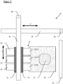
- FIG. 2 shows a top view of a 3D printing device 10.
- the 3D printing device 10 is essentially as with reference to FIG Figure 1 described.
- the 3D printing device 10 differs from the described device in that three discharge devices 14 are provided for pressure mass and three confocal measuring devices 20.
- the first two discharge devices 14 are as with reference to FIG Figure 1 described.
- the third discharge device 14 is designed as a further jetting nozzle 34 and is provided for setting support material.
- the confocal measuring devices 20 are each assigned to one of the discharge devices 14.
- the confocal measuring devices 20 and the discharge devices 14 are arranged opposite one another on the transport carriage 32, which moves the print head 12 along the Y axis.
- Figure 3 shows a side view of a height measurement according to an embodiment of the invention.
- a jetting nozzle 16 and the confocal measuring device 20 are shown above the base plate 24.
- the jetting nozzle 16 deposits droplets 36 which form the printed voxels when they strike the object 22 or the base plate 24.
- the jetting nozzle 16 is arranged behind the confocal measuring device 20, so that when printing, a height measurement is first carried out via the confocal measuring device 20, so that the positions at which printing masses to be printed can be printed can be determined without contact.
- the confocal measuring device 20 can also be used for the preliminary scan. However, the confocal measuring device 20 can also be used in such a way that the positions of printed printing masses are non-contact after printing can be determined, for example in order to obtain a CAD model of the printed object 22.
- a first printing error is a defect 38 which has already been measured by the confocal measuring device 20 and which can be corrected by the printing device 10 according to the invention while the current layer is being printed.
- the 3D printing device 10 determines that it is only a single or a few non-printed voxels, so that the defect 38 can be remedied immediately by a targeted reprint.
- the printed object 22 has another printing error in the form of an air pocket 40, i.e. a defect 38, which is already completely enclosed by pressure mass.
- the air inclusion 40 can be recognized by the confocal measuring device 20, since several interfaces of pressure mass and air occur in the measuring light beam, so that, provided the air inclusion 40 is still in the measuring range of the confocal measuring device 20, there are several dominant wavelengths in the received signal. If the air inclusion 40 is recognized, an error message can be generated, for example, or a message can be sent to the main control device, so that the printed object 22 can be imposed, for example, or further quality checks can be carried out. In the field of optics and medical technology in particular, such errors as the air trap 40 are often not permissible and their detection is therefore necessary. In the event of an error that cannot be corrected, the time to detect the error is reduced to a minimum.
- Another printing error is shown in the form of an elevation above the object 22 and shows a possible inclusion of foreign material 42 of a material, for example from the environment, e.g. B. dust particles, or which can consist of hardened, separated material from the jetting nozzle 16.
- the foreign material inclusion 42 can be confocal Measuring device 20 can be recognized because the distance to the object 22 changes briefly. With the presented 3D printing device, it can be determined whether the foreign material inclusion 42 is the same material as the object 22, namely printing mass or supporting mass, or a different material, since the reflection properties of the interface environment / foreign material inclusion 42 are different than at the interface environment / object 22.
- the foreign material inclusion 42 After detection of the foreign material inclusion 42, it can be provided, so far as can be determined that it is on the surface of the object 22, ie above the printed layers of the object 22, to generate corresponding warning messages the user can intervene, or provision can be made for the foreign material inclusion 42 to be removed automatically, for example with the aid of a robot arm.
- a foreign component 44 is also shown, which has been positioned, for example, using a rotor arm or manually on the printed object 22.
- the foreign component 44 is to be overprinted with one or more layers of printing compound, so that it is finally embedded in the object 22.
- the foreign component 44 is shown here as a cuboid, but it can also be a very flat foreign component 44, for example an electronic circuit board or a microchip.
- the position of the foreign component 44 is determined.
- the surface of the object 22 with the foreign component 44 positioned therein is measured in the scanning step by means of the confocal measuring device 20 and the position of a surface on which printing masses to be printed can be printed is determined.
- the determined data can, for example, be transferred to the control system in order to create a CAD model therefrom or to update the CAD model of the object 22.
- the distance between the jetting nozzle 16 and the last printed layer is shown as the discharge height h 1 .
- the distance between the confocal measuring device 20 and the last printed layer is shown as h.
- the geometry can be used to convert the two quantities into each other. Since the foreign component 44 on the printed object 22 in height by an amount measured by the confocal measuring device 20, can be provided when overprinting the foreign component 44, the distance of the jetting nozzle 16 to the base plate 24 by the corresponding amount, so that the discharge height h 1 above Object 22 remains constant during printing to keep the quality of printed object 22 constant.
- Figure 4 shows a side view of a height measurement according to a further embodiment of the invention. Shown is a dispenser 18 with a confocal measuring device 20 running on the base plate 24 while the object 22 is being printed.
- the dispenser 18 deposits strands 46 of printing material on the base plate 24, so that layers 48 are formed.
- the distance between the dispenser 18 and the last printed layer is again shown as the discharge height h 1 . If the discharge height h 1 is sufficient, the printed strand 46 ideally has a cylindrical strand cross section.
- the strand 46 is easily deformed by the movement of the dispenser 18. A further deformation of the strand 46 also results when the discharge height h 1 is too low.
- the deformation can be corrected by the continuous measurement or calculation of the discharge height h 1 by the confocal measuring device 20, e.g. B. by adjusting the discharge height h 1 .
- Figure 4 also shows an embodiment of the system 21 with the confocal measuring device 20.
- the system 21 refers to the confocal measuring device 20 and an evaluation unit 58, which are functionally connected to one another.
- the evaluation unit 58 is embodied integrated in a controller 23.
- the controller 23 comprises an external light source 50, a spectrometer 52 and the evaluation unit 58 in a common housing.
- the evaluation unit 58 and / or the light source 50 can be provided as suitable external units by means of suitable interfaces.
- the confocal measuring device 20 has a light source 50, which is, for example, a white light source with a homogeneous light spectrum, in particular a white light LED.
- the light from the light source 50 is guided by means of an optical waveguide 25 to a confocal lens arrangement 54, which was indicated in the drawing by way of example by four collimator lenses. Due to the confocal lens arrangement 54, the light emanating from the light source 50 experiences a chromatic aberration, so that blue light is refracted more than red light.
- a filter 56 is arranged behind the confocal lens arrangement 54, which filters out those spectral components of the light source 50 which lead to an unwanted hardening of the printed but not yet hardened layers 48.
- the light from the light source 50 is directed toward the last printed layer 48 or to that Figure 3 described flaws 38, air pockets 40 and surfaces of foreign components 44, it is reflected on them and runs via the same light path, namely via the filter 56, the confocal lens arrangement 54 and the optical waveguide 25 back to the controller 23, in the measurement of the reflected light he follows.
- the spectrometer 52 is connected to the evaluation unit 58.
- the evaluation unit 58 typically includes a CPU and storage means, as well as suitable interfaces to further computing units or to output devices such as printers, monitors, etc. In particular, it has a module for determining the dominant wavelengths in the spectrum detected by the spectrometer 52, and a database that provides an assignment of frequencies of the dominant wavelength, wavelength intensity and material.
- the spectrometer 52 and the evaluation unit 58 are thus set up to measure single- or multi-layer materials, so that the discharge height h 1 can be calculated and so that z. B. also related to Figure 3 defects 38 described, air pockets 40 and surfaces of foreign components 44 can be detected.
- the confocal measuring device 20 has in the focus area, ie. H. on the surface of the object 22, a light spot diameter in the range of 5 microns to 100 microns, preferably about 50 microns.
- the resolution of the system 21 when determining the distance between the print head 12 or the confocal measuring device 20 from the surface can be in the range from 10 nm to 0.5 ⁇ m, preferably between 20 nm and 50 nm.
- the confocal measuring device 20 is preferred in this way designed that it has at least in the X and Y direction between 100 and 200 microns accuracy, which corresponds approximately to the size of a voxel. The accuracy is also limited by the measurement tolerance in mechanics, i.e. H. due to the rigidity of the attachment of the confocal measuring device 20 and the discharge device 14 to the transport carriage 32.
- Figure 5 shows a jetting nozzle 16 in a side view above the base plate 24, the base plate 24 being shown at two different discharge heights h 1 relative to the jetting nozzle 16. Due to tolerance in the mechanics and in the nozzle geometry, the droplets that are applied, shown here as pressure jets 37, are not ejected vertically, but are within a certain tolerance range, which forms a cone 70.
- the cone 70 is shown with a cone opening ⁇ .
- the tip of the cone 70 forms an outlet opening 68 of the jetting nozzle 16.
- FIG Figure 5 By printing predetermined printing figures or printing patterns and by measuring the position or surface of the printing figures, a determination of the trajectory tolerance is shown in FIG Figure 5 with ⁇ X1 (h 1 ) and ⁇ X2 (h 1 ), depending on the discharge height h 1 . The values then obtained can be used to adjust a discharge angle ⁇ of the jetting nozzle 16 or provide guide values for a wear indicator of the jetting nozzle 16.
- Figure 6 shows the base plate 24 twice in a lateral sectional view, on which (purely by way of example three) test bodies 62 are arranged at a certain distance from one another.
- the base plate 24 can be compared with a standard position 74 be determined.
- the tilt and offset of the base plate 24 in the Y direction are also measured.
- the position of a printing plane 60 can be described by specifying the tilt and the offset. After determining the tilt and the offset, the position of the pressure plane 60 can be adjusted manually or automatically to take the standard position 74.
- Figure 7 shows a perspective view of the base plate 24 with a correcting device 72 acting thereon.
- the correcting device 72 is, for example, functionally connected to the system 21 with the confocal measuring device 20 via the main control device and is set up to correct the position of the pressure plane 60.
- the correction device 72 has offset actuators 64 and tilt actuators 66, by means of which the actuators with reference to Figure 6 described offset ⁇ X and ⁇ Y and ⁇ Z and the tilt ⁇ of the base plate 24 are adjustable.
Landscapes
- Engineering & Computer Science (AREA)
- Chemical & Material Sciences (AREA)
- Materials Engineering (AREA)
- Manufacturing & Machinery (AREA)
- Physics & Mathematics (AREA)
- Optics & Photonics (AREA)
- Mechanical Engineering (AREA)
- Health & Medical Sciences (AREA)
- Toxicology (AREA)
- Robotics (AREA)
- Human Computer Interaction (AREA)
- General Physics & Mathematics (AREA)
- Automation & Control Theory (AREA)
- Chemical Kinetics & Catalysis (AREA)
- Medicinal Chemistry (AREA)
- Polymers & Plastics (AREA)
- Organic Chemistry (AREA)
Description
- Die Erfindung betrifft ein Verfahren zum Herstellen von Objekten unter Einsatz einer 3D-Druckvorrichtung.
- Zur Herstellung von Prototypen, Kleinserien oder Einzelstücken von Gegenständen ist aus dem Stand der Technik eine Vielzahl verschiedener generativer Fertigungsverfahren bekannt. Diese auch als 3D-Druck bezeichneten Verfahren haben gemeinsam, dass eine Fertigung von Gegenständen bzw. Objekten direkt auf Basis eines Computermodells erfolgt. Vorteilhaft lassen sich so kostengünstig und einfach kundenspezifische Bauteile anfertigen. Zur Herstellung eines Objekts wird beispielsweise ein Pulver durch Aufbringen eines Härters selektiv verfestigt, wobei der Härter in einem vom herzustellenden Objekt abhängigen Muster auf das Pulver aufgetragen wird. Weitere Verfahren umfassen das Lasersintern, bei dem nach einem vorgegebenen Muster Pulver durch Aufschmelzen mit einem Laser in der gewünschten Form verfestigt wird, sowie Fused Filament Fabrication, bei dem das Objekt schichtweise aus einem schmelzfähigen Kunststoff hergestellt wird. Ebenfalls bekannt sind Verfahren, bei denen Flüssigkeit tröpfchenweise mit Düsen abgegeben und beispielsweise durch Einwirkung von UV-Strahlung ausgehärtet wird.
- Die 3D-Druckeinrichtungen unterliegen mechanischen Toleranzen in der Fertigung sowie mechanischem Verschleiß. Mechanische Toleranzen betreffen z. B. die Lage und die Ausrichtung des Druckkopfs zur Druckebene und die Ebenheit der Druckebene. Diese Toleranzen beeinflussen die Qualität des gedruckten Objekts, so dass Fehldrucke auftreten können. Insbesondere bei größeren Objekten oder Bauteilen ergeben sich oft unzureichende Druckbilder.
- In
DE 10 2012 000 664 A1 wird eine Vorrichtung für den 3D-Druck beschrieben, wobei der Drucktisch zur Einstellung von mechanischen Toleranzen mittels einstellbarer Positionierschrauben in der Ausrichtung zur Druckebene verändert werden kann. - In
DE 20 2015 103 932 U1 wird eine Vorrichtung zur Vermessung von Unebenheit einer Trägerplatte beschrieben, auf der ein Objekt generativ erzeugt wird. Dabei ist ein Sensor vorgesehen, der mit einer Extrudiervorrichtung unbeweglich verbunden ist, um die Oberfläche der Trägerplatte oder der zuletzt gedruckten Schicht zu vermessen. - In
DE 10 2001 106 614 A1 wird ein 3D-Druckverfahren beschrieben, welches mittels variabler Ausrichtung, Positionierung und Neigung des Drucktisches oder des Bauteilhalters spezielle 3D-Drucke von Überhängen oder freitragenden Elementen durchführt. Dabei wird der Druckkörper durch mehrachsige Aktoren so ausgerichtet, dass die Druckeinrichtung den Druckvoxel senkrecht auf der Druckebene platzieren kann. Die Position der Druckebene ist aus eingegebenen Daten bekannt und wird nicht ermittelt oder verifiziert. Es handelt sich um ein rein gesteuertes und kein geregeltes Verfahren. InUS2016/023403 A1 wird ein 3D-Druckverfahren beschrieben, wobei ein räumliches Mapping durchgeführt wird. - Die aus dem Stand der Technik bekannten Geräte weisen Defizite auf, welche die Qualität der gedruckten Teile beeinflussen. Die erzielbare Qualität der Objekte erreicht insbesondere im Falle des Drucks von Silikonmaterial nicht die konstante Qualität vergleichbarer, mittels Spritzguss hergestellter Objekte. Auch ist es bei den bekannten Vorrichtungen und Verfahren nicht möglich, eine gleichbleibende Qualität des Endproduktes sicherzustellen, wie es für den industriellen Einsatz der hergestellten Objekte unabdingbar ist.
- Eine Aufgabe der Erfindung ist es, ein verbessertes Verfahren zur generativen Fertigung von Objekten bereitzustellen, mit denen Objekte hoher Qualität, z. B. in Bezug auf Oberfläche und Formtreue, herstellbar sind.
- Es wird eine 3D-Druckvorrichtung zur Herstellung von Objekten im 3D-Druckverfahren vorgeschlagen, mit zumindest einem Druckkopf, der zumindest eine Austragevorrichtung aufweist, die eingerichtet ist, um Druckmassen an Soll-Positionen zu setzen, um Objekte generativ zu erzeugen, wobei die 3D-Druckvorrichtung ein System mit zumindest einer konfokalen Messvorrichtung aufweist, das dazu eingerichtet ist, berührungslos einen Abstand des Druckkopfs zu einer Oberfläche zu bestimmen, auf der zu druckende Druckmassen gedruckt werden können.
- Aus dem Abstand des Druckkopfs zu der Oberfläche, auf der die zu druckenden Druckmassen gedruckt werden können, und aus der Position des Druckkopfs ist die Position eines Punkts auf der Oberfläche bestimmbar, an dem eine Druckmasse abgelegt werden kann.
- Die 3D-Druckvorrichtung umfasst typischerweise eine Basisplatte, auf der das Objekt durch Austragen von Druckmasse aus der mindestens einen Austragevorrichtung des mindestens einen Druckkopfs aufgebaut wird. Basisplatte und Druckkopf werden hierbei relativ zueinander bewegt, wobei Relativbewegungen in allen drei Raumrichtungen X, Y und Z möglich sind. Hierzu kann beispielsweise der Druckkopf derart angeordnet sein, dass dieser in X- und Y-Richtung beweglich ist und die Basisplatte kann derart angeordnet sein, dass diese in Z-Richtung beweglich ist. Auch weitere Konfigurationen sind hierbei denkbar, beispielsweise kann die Basisplatte in Y-Richtung beweglich angeordnet werden und der Druckkopf kann derart angeordnet werden, dass dieser in X- und Z-Richtung beweglich ist. Alternativ oder zusätzlich hierzu kann vorgesehen sein, die Basisplatte und/oder den Druckkopf schwenkbar auszugestalten, so dass beliebige Raumanordnungen möglich sind.
- Um mit den ausgetragenen Druckmassen ein Objekt aufzubauen, werden die Druckmassen gemäß einem vorgegebenen Schema auf der Basisplatte abgelegt, wobei eine erste Materialschicht ausgebildet wird. Nach dem Ausbilden der ersten Materialschicht wird z. B. der Abstand zwischen der Austragevorrichtung und der Basisplatte vergrößert und es wird die nächste Materialschicht ausgebracht. Es folgen weitere Materialschichten, die jeweils nach einem vorgegebenen Schema abgelegt werden, bis das gewünschte Objekt fertiggestellt ist. Dies wird auch als generative Erzeugung des Objekts bezeichnet.
- Das Austragen der Druckmassen erfolgt nach einem Schema, welches aus einer Vorlage abgeleitet wird. Die Vorlage wird mit einer CAD-Software (Computer-Aided Design, rechnerunterstütztes Konstruieren) entworfen oder wird durch dreidimensionales Scannen eines Gegenstands erstellt. Zur Ableitung des Schemas für den Materialaustrag berechnet die Software typischerweise horizontale Schnitte der Vorlage, wobei jeder dieser Schnitte einer Materialschicht entspricht. Im Anschluss wird berechnet, wie die Druckmassen in der jeweiligen Schicht platziert werden müssen. Hierbei wird berücksichtigt, ob der Austrag der Druckmassen in Form von Voxeln, in Form von Strängen oder in einer Kombination aus Voxeln und Strängen erfolgt.
- Gegebenenfalls wird beim Ableiten des Schemas auch das Setzen von Stützmaterial eingeplant. Das Setzen von Stützmaterial kann erforderlich sein, wenn das herzustellende Objekt Hohlräume, Hinterschnitte, überhängende, freitragende oder dünnwandige Teile aufweisen soll, da die Druckmassen nicht frei im Raum schwebend gesetzt werden können. Das Stützmaterial füllt während des Druckprozesses Raumvolumina aus und dient als Basis oder als Gerüst, um darauf die Druckmassen setzen und aushärten zu können. Das Stützmaterial wird nach Beendigung des Druckprozesses wieder entfernt und gibt die Hohlräume, Hinterschnitte sowie überhängenden, freitragenden oder dünnwandigen Partien des Objekts frei. In der Regel wird als Stützmaterial ein von dem Material des zu druckenden Objekts abweichendes Material verwendet, z. B. nicht vernetzendes und nicht kohäsives Material. Abhängig von der Geometrie des Objekts wird die notwendige Form des Stützmaterials berechnet. Bei der Berechnung der Form des Stützmaterials können verschiedene Strategien eingesetzt werden, um beispielsweise möglichst wenig Stützmaterial zu verwenden oder um die Maßhaltigkeit des Produktes zu erhöhen.
- Die Austragevorrichtung ist eingerichtet, in Richtung der Austragsachse Druckmassen in Form einzelner isolierter Tropfen, als Tropfenreihe oder in Form eines Strangs abzugeben. Fließende Übergänge zwischen diesen Formen sind möglich. Im Rahmen dieser Beschreibung wird ein aus der Austragevorrichtung ausgetragener und auf der Basisplatte bzw. auf dem Objekt gesetzter Tropfen einer Druckmasse als Voxel bezeichnet. Mit Strang wird sowohl ausgetretene und noch nicht gesetzte als auch gesetzte Druckmasse in Strangform bezeichnet. Unter einer gesetzten Druckmasse wird sowohl ein Voxel als auch ein Strang verstanden.
- Zur Abgabe einzelner Tropfen kann die Austragevorrichtung eine oder mehrere Düsen umfassen, die Flüssigkeitstropfen aus Druckmasse in Richtung der Basisplatte emittieren, ähnlich wie es die Düsen eines Tintenstrahldruckers tun. Daher werden diese Düsen auch als Jetting-Düsen bezeichnet.
- Zur Abgabe von Strängen aus Druckmasse wird die Druckmasse mittels Druckbeaufschlagung eines Vorratsbehälters, z.B. aus einer Kartusche, Spritze oder einem Fass, durch eine Düse als Strang herausgepresst und auf der Basisplatte zum Objekt selektiv abgeschieden. Derartige Austragevorrichtungen werden im Rahmen dieser Beschreibung als Dispenser bezeichnet.
- Es können mehrere, auch technisch unterschiedliche Austragevorrichtungen für verschiedene Druckmassen in der 3D-Druckvorrichtung vorgesehen sein. So kann die 3D-Druckvorrichtung eine oder mehrere ggf. unterschiedlich ausgestaltete oder unterschiedlich betriebene Jetting-Düsen und/oder einen oder mehrere ggf. unterschiedlich ausgestaltete oder unterschiedlich betriebene Dispenser aufweisen. Die Austragevorrichtung kann auch Düsen- oder Dispenserarrays aufweisen, die mehrere Tropfen bzw. Stränge gleichzeitig abgeben können.
- Insbesondere kann ein Druckkopf mehrere verschiedene Austragevorrichtungen aufweisen, z.B. eine oder mehrere Jetting-Düsen und/oder einen oder mehrere Dispenser. Hierbei können beispielsweise über den oder die Dispenser schnell die Druckmassen im Inneren des Objekts gesetzt werden und mit der oder den Jetting-Düsen in hoher Qualität die Oberfläche des Objekts hergestellt werden. Alternativ ist es denkbar, dass der Druckkopf mehrere gleichartige Austragevorrichtungen umfasst. Hierdurch können beispielsweise mehrere Objekte gleichzeitig generativ hergestellt werden oder es kann mit mehreren Austragevorrichtungen parallel an dem Aufbau eines einzelnen Objekts gearbeitet werden. In beiden Fällen wird die insgesamt erforderliche Druckdauer reduziert.
- Die jeweilige Austragevorrichtung weist eine Austragsachse auf, die die Richtung angibt, in die Material aus der Austragevorrichtung ausgetragen wird. Üblicherweise ist die Austragsachse derart mit Bezug zur Basisplatte orientiert, dass diese senkrecht zur Basisplatte steht. Optional kann vorgesehen sein, dass die 3D-Druckvorrichtung derart konfiguriert ist, dass auch die Ausrichtung der Austragsachse relativ zur Basisplatte verändert werden kann.
- Bevorzugt weist der Druckkopf eine oder mehrere Jetting-Düsen auf. Die Jetting-Düsen sind derart eingerichtet, dass diese, auf Anforderung, kontrolliert einen Tropfen abgeben.
- Es kann beispielsweise ein Heizelement in der Jetting-Düse vorgesehen sein, mit dem die Druckmasse erhitzt wird und ein Tropfen von einer entstehenden Dampfblase aus der Jetting-Düse getrieben wird, dies ist als Bubble-Jet bekannt.
- Eine weitere Möglichkeit ist das Anordnen eines Piezoelements, welches sich aufgrund einer elektrischen Spannung verformt und hierdurch einen Tropfen aus einer Jetting-Düse pressen kann. Derartige Tintenstrahldruckverfahren sind dem Fachmann aus dem klassischen Druck und aus dem sogenannten 3D-Druck, bei dem aus einer fotopolymerisierbaren Tinte dreidimensionale Gegenstände schichtweise aufgebaut werden, grundsätzlich bekannt. Derartige Druckköpfe, wie sie im Tintenstrahldruck oder in Multijet-3D-Druck eingesetzt werden, können auch niederviskose Drucktinten bzw. Druckmassen dosieren, z.B. solche mit Viskositäten unter 50 mPa·s.
- In den Druckköpfen in dem erfindungsgemäßen Verfahren werden bevorzugt Austragevorrichtungen eingesetzt, die auf Jet-Ventilen mit Piezoelementen basieren. Diese ermöglichen das Austragen sowohl niedrigviskoser Materialien, wobei Tropfenvolumen für Tropfen von einigen wenigen Pikolitern (pL) (2 pL entsprechen einem Tropfendurchmesser von ca. 0,035 µm) realisiert werden können, als auch mittel- und hochviskoser Materialien wie insbesondere Silikonkautschukmassen, wobei Piezo-Druckköpfe mit einem Düsendurchmesser zwischen 50 und 500 µm bevorzugt werden und Tropfenvolumen im Nanoliter-Bereich (1 bis 100 nL) erzeugt werden können. Mit niedrigviskosen Massen (< 100 mPa·s) können diese Druckköpfe Tröpfchen mit sehr hoher Dosierfrequenz abgeben (ca. 1 - 30 kHz), während mit höherviskosen Massen (> 100 Pa·s) in Abhängigkeit von den rheologischen Eigenschaften (scherverdünnendes Verhalten) Dosierfrequenzen bis zu ca. 500 Hz erzielt werden können. Geeignete Jetting-Düsen werden beispielsweise in
DE 10 2011 108 799 A1 beschrieben. - Bei bevorzugten Ausführungsformen der Jetting-Düsen kann beim Austrag der Druckmasse das Volumen des Tropfens beeinflusst werden, so dass Tropfen unterschiedlicher Größe erzeugt werden können. Alternativ oder zusätzlich hierzu kann vorgesehen sein, dass einige Jetting-Düsen, z.B. eines Düsenarrays, mit unterschiedlichen Düsengrößen ausgestaltet sind. Mit kleinen Tropfen lassen sich genauere Kannten erzeugen und z. B. ein Oberflächenfinish an den Seitenflächen des Objekts nach einem Drehen des Objekts durchführen.
- In einem Dispenser erfolgt der Druckaufbau z.B. mittels Luftdruck oder mechanisch, z.B. durch einen kleinen Extruder, mittels einer Kolbenpumpe oder mittels einer Exzenterschnecke. Verschiedene Ausführungsformen sind dem Fachmann bekannt.
- Im Fall einer Jetting-Düse als Austragevorrichtung wird durch eine Steuereinrichtung vorgegeben, wann die Jetting-Düse einen Voxel austrägt. Des Weiteren kann vorgesehen sein, dass durch die Steuereinrichtung die Größe des Voxels vorgegeben wird. Es kann vorgesehen sein, dass in Abhängigkeit der Messergebnisse der konfokalen Messeinrichtung die Parameter der Jetting-Düse, welche die Voxelgröße beeinflussen, angepasst werden. Derartige Parameter können z. B. die Öffnungszeiten des Jettingventils umfassen, oder, falls die Düse Stößeltechnik aufweist, eine Stößelhubgeschwindigkeit, Stößelrückzugsgeschwindigkeit, und den Stößelhub. Die Parameter der Jetting-Düse, welche die Voxelgröße beeinflussen, können auch bei einem etwaigen Nachdruck fehlerhaft nicht-gesetzter Voxel, z. B. beim Auffüllen von Fehlstellen kurzfristig angepasst werden, um den Nachdruck zu optimieren.
- Im Fall eines Dispensers als Austragevorrichtung wird durch die Steuereinrichtung vorgegeben, wann der Dispenser mit dem Austragen von Druckmasse in Form eines Strangs beginnt und wann das Austragen beendet wird. Des Weiteren kann vorgesehen sein, dass der Volumenstrom, also der Druckmassenvolumenaustrag pro Zeiteinheit, durch die Steuereinrichtung vorgegeben wird. Es kann vorgesehen sein, in Abhängigkeit der Messergebnisse der konfokalen Messeinrichtung die Parameter des Dispensers, welche die Strangform beeinflussen, anzupassen, um die Druckqualität zu erhöhen. Derartige Parameter des Dispensers können die Durchflussrate, Zuführergeschwindigkeit und den Vordruck im Materialspeicher umfassen.
- Wird Stützmaterial eingesetzt, so kann der Druckkopf eine oder mehrere weitere Austragevorrichtungen für das Stützmaterial aufweisen. Alternativ oder zusätzlich kann für das Austragen von Stützmaterial auch ein weiterer Druckkopf mit entsprechenden Austragevorrichtungen vorgesehen sein.
- Die Druckmasse kann Masse zur Erzeugung eines dauerhaften Bauteils sein, insbesondere Silikon, oder sie kann Stützmaterial sein, das für temporär erzeugte Teile oder Bereiche benötigt wird, insbesondere in Form von z. B. Polyethylenglycol (PEG) oder Polyvinylalkohol (PVAL).
- Bei der verwendeten Druckmasse handelt es sich bevorzugt um ein Material, welches zumindest während der Verarbeitung in einer fließfähigen Form vorliegt und nach dem Austrag ausgehärtet werden kann. Durch die nachträgliche Aushärtbarkeit kann bei Feststellung eines Fehldrucks ein Prozess wie beispielsweise eine Reinigung des Druckkopfes gefolgt von einem Nachdruck fehlerhaft nicht-gesetzter Druckmassen durchgeführt werden, wobei die unvernetzten Materialien bis zur ihrer Aushärtung fließfähig bleiben, so dass die nachträglich gesetzten Druckmassen sich noch mit den vor der Reinigung gesetzten Druckmassen verbinden können.
- Bevorzugt ist vorgesehen, dass eine Aushärtung der Druckmassen mittels Strahlung oder Wärmeeinwirkung erfolgt, besonders bevorzugt ortsselektiv oder flächig mittels Strahlung oder Wärmeeinwirkung. Bevorzugt werden Druckmassen eingesetzt, die sich nach dem Setzen durch Einwirkung von Strahlung oder Wärme aushärten lassen.
- Beispielsweise wird bei dem vorgeschlagenen Verfahren eine Druckmasse eingesetzt, die sich durch Einwirkung von aktinischer Strahlung aushärten lässt, bevorzugt durch Einwirkung von UV/VIS-Strahlung. UV-Strahlung bzw. UV-Licht weist eine Wellenlänge im Bereich von 100 nm bis 380 nm auf, während sichtbares Licht (VIS-Strahlung) eine Wellenlänge im Bereich von 380 bis 780 nm aufweist.
- In dem erfindungsgemäßen Verfahren werden als Druckmasse Silikonkautschukmassen verwendet, die durch UV/VIS-induzierte Additionsreaktion vernetzen. Gegenüber einer thermischen Vernetzung hat die UV/VIS-induzierte Vernetzung Vorteile. Zum einen können Intensität, Einwirkungszeit und Einwirkungsort der UV/VIS-Strahlung genau bemessen werden, während das Aufheizen der ausgetragenen Druckmasse (wie auch deren anschließendes Abkühlen) durch die relativ geringe thermische Leitfähigkeit stets verzögert erfolgt. Aufgrund des intrinsisch sehr hohen thermischen Ausdehnungskoeffizienten der Silikone führen die bei thermischer Vernetzung zwangsläufig vorhandenen Temperaturgradienten zu mechanischen Spannungen, welche die Maßhaltigkeit des gebildeten Objekts negativ beeinflussen, was im Extremfall zu inakzeptablen Formverzerrungen führen kann.
- UV/VIS-induzierte Additions-vernetzende Silikonkautschukmassen werden beispielsweise in
DE 10 2008 000 156 A1 ,DE 10 2008 043 316 A1 ,DE 10 2009 002 231 A1 ,DE 10 2009 027 486 A1 ,DE 10 2010 043 149 A1 undWO 2009/027133 A2 beschrieben. Die Vernetzung kommt durch UV/VIS-induzierte Aktivierung eines lichtempfindlichen Hydrosylierungskatalysators zustande, wobei Komplexe des Platins bevorzugt sind. Aus dem Stand der Technik sind zahlreiche lichtempfindliche Platinkatalysatoren bekannt, die unter Lichtausschluss weitgehend inaktiv sind und durch Bestrahlung mit Licht mit einer Wellenlänge von 250-500 nm in bei Raumtemperatur aktive Platin-Katalysatoren überführt werden können. Beispiele hierfür sind (η-Diolefin)(σ-aryl)-Platinkomplexe (EP 0 122 008 A1 ;EP 0 561 919 B1 ), Pt(II)-β-diketonatkomplexe (EP 0 398 701 B1 ) und (η5-Cyclopentadienyl)tri(σ-alkyl)Platin(IV)-Komplexe (EP 0 146 307 B1 ,EP 0 358 452 B1 ,EP 0 561 893 B1 ). Besonders bevorzugt sind MeCpPtMe3 sowie die sich davon durch Substitution der am Platin befindlichen Gruppen ableitenden Komplexe, wie beispielsweise beschrieben inEP 1 050 538 B1 undEP 1 803 728 B1 . Die UV/VIS-induziert vernetzenden Druckmassen können ein- oder mehrkomponentig formuliert werden. - Die Geschwindigkeit der UV/VIS-induzierten Additionsvernetzung hängt von zahlreichen Faktoren ab, insbesondere von der Art und Konzentration des PlatinKatalysators, von der Intensität, Wellenlänge und Einwirkungszeit der UV/VIS-Strahlung, der Transparenz, Reflektivität, Schichtdicke und Zusammensetzung der Silikonkautschukmasse und der Temperatur.
- Der Platin-Katalysator wird vorzugsweise in einer katalytisch ausreichenden Menge eingesetzt, so dass eine hinreichend schnelle Vernetzung bei Raumtemperatur ermöglicht wird. Vorzugsweise werden 0,1 bis 500 Gew.-ppm des Katalysators bezogen auf den Gehalt des Pt-Metalls zur gesamten Silikonkautschukmasse verwendet, vorzugsweise 0,5 bis 200 Gew.-ppm, besonders bevorzugt 1 bis 50 Gew.-ppm.
- Für die Aushärtung der UV/VIS-induziert additions-vernetzenden Silikonkautschukmasse wird bevorzugt Licht der Wellenlänge 240 bis 500 nm, weiter bevorzugt 250 bis 400 nm, besonders bevorzugt 350 bis 400 nm, insbesondere bevorzugt 365 nm eingesetzt. Um eine rasche Vernetzung zu erzielen, worunter eine Vernetzungszeit bei Raumtemperatur von weniger als 20 min, vorzugsweise weniger als 10 min, besonders bevorzugt weniger als 1 min verstanden werden soll, empfiehlt sich die Verwendung einer UV/VIS-Strahlungsquelle mit einer Leistung zwischen 10 mW/cm2 und 20.000 mW/cm2, bevorzugt zwischen 30 mW/cm2 und 15.000 mW/cm2, sowie eine Strahlungsdosis zwischen 150 mJ/cm2 und 20.000 mJ/cm2, bevorzugt zwischen 500 mJ/cm2 und 10.000 mJ/cm2. Im Rahmen dieser Leistungs- und Dosis-Werte lassen sich flächenspezifische Bestrahlungszeiten zwischen maximal 2.000 s/cm2 und minimal 8 ms/cm2 realisieren.
- Werden Druckmassen eingesetzt, die unter UV/VIS-Einwirkung aushärten, so weist die 3D-Druckvorrichtung bevorzugt eine UV/VIS-Belichtungseinheit auf. Bei ortsselektiver Belichtung ist die UV/VIS-Quelle relativ zur Basisplatte beweglich angeordnet und beleuchtet nur ausgewählte Bereiche des Objekts. Bei einer flächigen Belichtung ist die UV/VIS-Quelle in einer Variante derart ausgestaltet, dass das gesamte Objekt bzw. eine gesamte Materialschicht des Objekts auf einmal belichtet wird. In einer bevorzugten Variante ist die UV/VIS-Quelle derart ausgebildet, ihre Lichtstärke oder ihre Energie variabel eingestellt werden kann und dass die UV/VIS-Quelle zur gleichen Zeit nur einen Teilbereich des Objekts belichtet, wobei die UV/VIS-Quelle derart relativ zu dem Objekt bewegt werden kann, dass das gesamte Objekt mit dem UV/VIS-Licht, ggf. in unterschiedlicher Intensität, belichtet werden kann. Beispielsweise ist die UV/VIS-Quelle hierzu als UV/VIS-LED Leiste ausgestaltet und wird relativ zu dem Objekt, bzw. über das gedruckte Objekt bewegt.
- Im Fall von mittels Wärmeeinwirkung aushärtender Druckmassen kann eine Infrarotlicht-Quelle (IR) eingesetzt werden, um eine ortsselektive oder flächige Wärmebehandlung durchzuführen.
- Für das Durchführen der Aushärtung wird eine Aushärtestrategie verwendet. Bevorzugt erfolgt eine Aushärtung der Druckmassen nach dem Setzen einer Schicht von Druckmassen, nach dem Setzen mehrerer Schichten von Druckmassen oder direkt während des Drucks.
- Ein Aushärten der Druckmassen direkt während des Drucks wird als direkt-Aushärtestrategie bezeichnet. Werden durch UV/VIS-Strahlung aushärtbare Druckmassen verwendet, so ist dann im Vergleich zu anderen Aushärtestrategien die UV/VIS-Quelle sehr lange aktiv, so dass mit sehr viel geringerer Intensität gearbeitet werden kann, was zu einem langsamen Durchvernetzen des Objekts führt. Dies begrenzt die Erwärmung des Objekts und führt zu maßhaltigen Objekten, da keine Ausdehnung des Objekts aufgrund von Temperaturspitzen auftritt.
- Bei der Pro-Layer-Aushärtestrategie erfolgt nach dem Setzen jeder vollständigen Materialschicht die strahlungsinduzierte Vernetzung der gesetzten Materialschicht. Während dieses Vorgangs verbindet sich die frisch gedruckte Schicht mit der ausgehärteten darunterliegenden gedruckten Schicht. Das Aushärten erfolgt nicht sofort nach dem Setzen einer Druckmasse, so dass die Druckmassen vor dem Aushärten Zeit haben, zu relaxieren. Hiermit ist gemeint, dass die Druckmassen ineinander fließen können, wodurch eine glattere Oberfläche als bei der Direkt-Aushärtestrategie erzielt wird.
- Bei der n-Layer-Aushärtestrategie wird ähnlich wie bei der Pro-Layer-Aushärtestrategie verfahren, jedoch wird das Aushärten erst nach dem Setzen von n Materialschichten vorgenommen, wobei n eine natürliche Zahl ist. Die für das Relaxieren der Druckmassen zur Verfügung stehende Zeit wird weiter erhöht, wodurch sich die Oberflächengüte weiter verbessert. Aufgrund des Fließens der Druckmassen kann die erzielbare Kantenschärfe jedoch abnehmen.
- In einer bevorzugten Ausführungsform wird die Aushärtestrategie mit dem Nachdrucken fehlerhaft nicht-gesetzter Druckmassen abgestimmt. Beispielsweise kann jeweils nach dem Drucken einer Materialschicht das Nachdrucken fehlerhaft nicht-gesetzter Druckmassen erfolgen, bevor die Vernetzung der gesetzten Materialschicht nach der Pro-Layer-Aushärtestrategie bzw. n-Layer-Aushärtestrategie erfolgt. Fehlerhaft nicht-gesetzte Druckmassen können beispielsweise dadurch erkannt werden, dass eine Positionsmesseinrichtung die Verfahrwege des Druckkopfes ermittelt, ggf. laufend ermittelt, dass der Austrag der Druckmasse aus der Austragevorrichtung überwacht wird und/oder dass ausgetragene Druckmasse vermessen wird.
- Die 3D-Druckvorrichtung weist ein System mit einer konfokalen Messvorrichtung auf, das dazu eingerichtet ist, berührungslos den Abstand des Druckkopfs zu der Oberfläche zu bestimmen, auf der zu druckende Druckmassen gedruckt werden können. Das System ist dazu eingerichtet, eine chromatisch-konfokale Abstandsmessung durchzuführen.
- Allgemein umfasst das System hierzu einen oder mehrere Sensoren und Auswerteeinheiten. Die konfokale Messvorrichtung wird auch als Sensor des Systems bezeichnet. Die Sensoren nehmen Messwerte auf, die von der Auswerteeinheit ausgewertet werden.
- Das System umfasst eine Lichtquelle. Die Lichtquelle ist bevorzugt als Punktlichtquelle realisiert, beispielsweise mittels einer Lochblende mit wenigen Mikrometern Durchmesser oder mittels eines Lichtwellenleiters. Sie sendet polychromatisches Licht auf die Linsenanordnung, z. B. breitbandiges Weißlicht mit hoher Intensität und gleichmäßiger spektraler Verteilung.
- Die konfokale Messvorrichtung umfasst zumindest eine Linsenanordnung, bei welcher die Linsen konfokal angeordnet sind. Die Linsenanordnung ist so ausgestaltet, dass das Licht auf kontrollierte Art in seine monochromatischen Wellenlängen zerlegt wird. Hierzu werden eine oder mehrere Linsen eingesetzt, welche dispersiv auf das Licht wirken, sodass blaue Lichtanteile näher an der Linse fokussiert werden und die roten Lichtanteile weiter weg, oder umgekehrt.
- Die konfokale Messvorrichtung berührt das Objekt dabei nicht, eine Wechselwirkung mit dem Objekt ergibt sich nur durch das Licht. Am und im Objekt erfolgt nach den bekannten Gesetzen der Optik eine Reflexion, Absorption und Transmission des Lichts. Das am Objekt reflektierte Licht, z. B. Reflexionslicht der Oberfläche des Objekts, Reflexionslicht der Basisplatte oder Reflexionslicht von Luft- oder Fremdkörpereinschlüssen, wird von der konfokalen Messvorrichtung empfangen und über die Linsenanordnung auf ein Spektrometer geführt.
- Aus den Messwerten des Spektrometers ermittelt die Auswerteeinheit eine oder mehrere dominante Wellenlängen, bzw. Spektralfarben des reflektierten Lichts. Die dominanten Wellenlängen können im Rahmen der vorliegenden Offenbarung auch als "Peaks" bezeichnet werden. Die Auswerteeinheit ist so kalibriert, dass jeder Wellenlänge des reflektierten Lichts ein bestimmter Abstandswert zum Messobjekt, z. B. zur letzten gedruckten Schicht des Objekts oder zur Basisplatte, zugeordnet ist. Aus dem Wissen über die Fokusweiten der einzelnen Wellenlängen kann jeder dominanten Wellenlänge direkt ein Abstandswert zum Messobjekt zugeordnet werden. Insbesondere wird zunächst diejenige Lichtwellenlänge zur Messung herangezogen, die sich exakt auf der Oberfläche des gedruckten Objekts (bzw. vor dem Druck und außerhalb des gedruckten Objekts auf der Basisplatte) fokussiert. Die Auswerteeinheit kann hieraus den Abstand des Druckkopfes zu der Oberfläche bestimmen, an denen weitere zu druckende Druckmassen gedruckt werden können. Ist das Druckmaterial transparent, dann können weitere dominante Wellenlängen auftreten, die auch als weitere "Peaks" bezeichnet werden. Weitere Peaks treten aufgrund des Übergangs vom optisch dünneren Medium zum optisch dichteren Medium oder umgekehrt z. B. bei Luft- oder Fremdkörpereinschlüssen im Objekt auf. Eine weitere dominante Wellenlänge ergibt sich an der Grenze Objekt / Basisplatte. Die Oberfläche des gedruckten Objekts ist dabei der von den kurzen Wellenlängen aus gesehen erste Peak und die Basisplatte ist der letzte Peak. Die Auswerteeinheit kann zur Auswertung insbesondere Software-implementierte Komponenten aufweisen.
- Die bevorzugte Auflösung der Abstandsmessung liegt im Bereich von 10 bis 500 nm, bevorzugt 10 bis 200 nm, weiter bevorzugt 20 bis 50 nm, besonders bevorzugt bei etwa 28 nm. Der Messbereich der Abstandsmessung liegt bevorzugt im Bereich von 0,3 bis 30 mm, bevorzugt 0,5 bis 3 mm, besonders bevorzugt bei etwa 1 mm. Die bevorzugte Größe des Lichtfleckdurchmessers liegt im Bereich von 5 bis 100 µm, bevorzugt 5 bis 50 µm, weiter bevorzugt 6 bis 9 µm, besonders bevorzugt bei etwa 8 µm. In X- und Y-Richtung weist die konfokale Messvorrichtung bevorzugt zwischen 100 und 200 µm Genauigkeit auf.
- Weil als Material Silikonkautschukmasse verwendet wird, die durch UV/VIS-induzierte Additionsreaktion vernetzt, ist bevorzugt vorgesehen, dass das zur Abstandsmessung verwendete Licht keine Komponenten enthält, die ungewollt zur Aushärtung der Silikonkautschukmasse führen. Wird beispielsweise UV/VISinduziert Additions-vernetzende Silikonkautschukmasse eingesetzt, die bei Licht der Wellenlänge 240-500 nm, bevorzugt 250-400 nm, besonders bevorzugt 350-400 nm, insbesondere bevorzugt 365 nm vernetzt, dann kann gemäß einer ersten Ausführungsform also vorgesehen sein, dass die Lichtquelle der konfokalen Messvorrichtung keine Anteile dieses Lichts aussendet, z. B. Weißlicht ohne Anteile dieses Lichts. Alternativ oder zusätzlich hierzu kann die konfokale Messvorrichtung einen oder mehrere Filter aufweisen, um die entsprechenden Anteile des Lichts herauszufiltern.
- Dadurch, dass die Messung die gedruckten Schichten nicht beeinflusst, ist es insbesondere auch möglich, mehrere Schichten aufeinander zu drucken und dabei zu vermessen, ohne jede Schicht dabei direkt auszuhärten (n-Layer-Strategie).
- Die Bestimmung des Abstands des Druckkopfes zu der Oberfläche, an denen zu druckende Druckmassen gedruckt werden können, erfolgt in Bezug auf die Basisplatte, aber auch in Bezug auf bereits gedruckte Schichten, wobei diese im Falle von Silikon oder Silikonelastomer oftmals transparent sind. Bevorzugt ist das System mit der konfokalen Messvorrichtung daher dazu eingerichtet, die Positionen, an denen die zu druckenden Druckmassen gedruckt werden können, auf einer Schicht zu bestimmen, die zumindest teilweise aus einer transparenten Druckmasse gebildet ist, insbesondere auf einer Schicht mit einem Silikon oder Silikonelastomer. Vorteilhaft sind das Spektrometer und die Auswerteeinheit des Systems dazu eingerichtet, die schwache Reflektion an der Grenzfläche zwischen zwei verschiedenen optisch dichten Medien (z. B. Luft / Silikon) zu detektieren.
- Gemäß einer bevorzugten Ausführungsform ist das System mit der konfokalen Messvorrichtung außerdem dazu eingerichtet, Luft- und Fremdmaterialeinschlüsse in gedruckten Schichten zu bestimmen.
- Die Auswerteeinheit wertet hierzu die Lage aller im Spektrometer detektierten auftretenden dominanten Wellenlängen aus. Bei Luftblasen und bei transparenten Fremdkörpern in gedruckten Schichten treten zusätzlich zur Objektoberfläche und zur Basisplatte weitere dominante Wellenlängen auf. Bei Einschlüssen von undurchsichtigen, d. h. opaken Fremdkörpern verschiebt sich oder verschwindet z. B. die dominante Wellenlänge der Basisplatte. Fehlstellen wie Einschlüsse von Fremdmaterial oder Luftblasen können damit erkannt werden. Werden Fremdkörper oder Lufteinschlüsse detektiert, können entsprechende Fehlermeldungen erzeugt werden, die auf einen Fehldruck hinweisen. Es kann auch vorgesehen sein, dass das System Komponenten umfasst, die die Fehler korrigieren, beispielsweise durch zusätzlichen Druck von Druckmasse bei Fehlstellen oder durch Entfernen der Fremdkörper, beispielsweise mittels eines Roboterarms.
- Da der Abstand des Fokuspunktes von der Linse vom Brechungsindex des Mediums abhängig ist, wird bei der Bestimmung des Abstands von Fehlstellen und Einschlüssen (z. B. in einem transparenten Objekt) eine Abstandskorrektur vorgenommen. Dabei wird der materialabhängige Brechungsindex des Objekts bzw. des Mediums berücksichtigt.
- Bevorzugt ist das System mit der konfokalen Messvorrichtung außerdem dazu eingerichtet, zu bestimmen, auf welches Material die zu druckenden Druckmassen gedruckt werden können.
- Die Auswerteeinheit wertet hierzu die Intensität aller im Spektrometer auftretenden dominanten Wellenlängen aus. Dabei unterscheidet sie zwischen Druckmasse, Stützmaterial und Material der Basisplatte. Weiterhin kann die Auswerteeinheit auch zwischen Materialien unterscheiden, die nebeneinander in einer ebenen Fläche gedruckt werden, z. B. beim im Folgenden beschriebenen Applikationsdruck, oder wenn z. B. ein Material in einem weiteren Material eingebettet wird. Um den Übergang von einem transparenten Material zu einem intransparenten Material zu detektieren, kann auch das Verschwinden der Reflexion der Basisplatte herangezogen werden, sofern es noch im Messbereich der konfokalen Messvorrichtung liegt.
- Aufgrund von Verschleiß oder mechanischer Einwirkungen verändert sich im Laufe der Zeit die Ausrichtung der Basisplatte zum Druckkopf. Gemäß einer bevorzugten Ausführungsform ist das System mit der konfokalen Messvorrichtung außerdem dazu eingerichtet, die Lage einer Druckebene zu bestimmen, in der die zu druckenden Druckmassen gedruckt werden. Die Auswerteeinheit bestimmt die Lage der Druckebene anhand mehrerer nicht auf einer Linie befindlicher gemessener Abstände.
- Beispielsweise wird hierzu eine Messpunktmatrix verwendet, die zumindest dem Rang der Druckpunktmatrix entspricht. Beim Dispensdruck wird die Messpunktmatrix zumindest dem Rang der Positionsmatrix des Druckkopfes erhalten. Die bevorzugte Größe des Lichtfleckdurchmessers im Bereich von 5 µm bis 100 µm bei einer Auflösung der Abstandsmessung im Bereich von 10 bis 200 nm, bevorzugt etwa 20 bis 40 nm erlaubt das Vermessen jedes einzelnen gesetzten Voxels.
- Für den Fall, dass noch kein Material gedruckt wurde, bildet die Basisplatte, auf der das zu druckende Objekt aufgebaut wird, die Druckebene. Wenn schon erste Schichten gedruckt worden sind, kann die Druckebene aber auch durch die Lage der zuletzt gedruckten Schicht beschrieben werden.
- Die Lage der Druckebene kann beispielsweise durch Angabe von Versatz und Verkippung gegenüber dem Druckkopf bzw. zur Druckkopfebene beschrieben werden, oder auch durch Angabe des Abstands zum Druckkopf und der Orientierung im Raum. Hierzu weist die Auswerteeinheit entsprechende Softwaremodule auf.
- Bei Kenntnis der Lage der Druckebene kann das System kalibriert werden, z. B. indem Versatz und Verkippung gegenüber dem Druckkopf bzw. der Druckkopfebene oder der Abstand der Druckebene in Bezug auf die jeweilige Austragevorrichtung und die Orientierung im Raum eingestellt werden. Nach einer bevorzugten Ausführungsform weist die 3D-Druckvorrichtung daher eine Korrigiervorrichtung auf, die funktionell mit dem System der konfokalen Messvorrichtung verbunden und dazu eingerichtet ist, die Lage der Druckebene zu korrigieren.
- Die Korrigiervorrichtung kann Justierelemente zur Justierung der Druckebene umfassen, z. B. Justierschrauben an der Basisplatte und am Druckkopf. Die Justierung der Druckebene kann mechanisch per Hand erfolgen oder automatisch. Bevorzugt umfasst die Korrigiervorrichtung ansteuerbare Aktoren, die z. B. Verkippung und Versatz automatisch per Computersteuerung einstellen können.
- Für den Fall, dass die Austragevorrichtung eine Jetting-Düse ist, kann die Korrigiervorrichtung auch Justierelemente zur Justierung der Ausrichtung des Druckkopfs aufweisen, beispielsweise Winkeljustierschrauben. Durch Toleranz in der Mechanik und in der Düsengeometrie werden ausgebrachte Tropfen, die zu Druckvoxeln führen, nicht senkrecht ausgestoßen, sondern in einem kegelförmigen Toleranzbereich. Die Spitze des Kegels ist dabei durch den Düsenausgang gebildet und die Grundfläche der Bereich auf der Druckebene, auf welcher der Tropfen auftrifft. Eine nicht senkrechte Ausrichtung des Druckkopfes, Toleranzen der Düsenformung sowie Verschmutzungen und Ablagerungen in der Düse oder Luftströmungen können eine ungewollte Ablenkung der Tropfentrajektorien erzeugen. Bevorzugt sind auch hier ansteuerbare Aktoren vorgesehen, um den Winkel automatisch per Computersteuerung einstellen zu können.
- Die konfokale Messvorrichtung ist gemäß einer bevorzugten Ausführungsform ortsfest in Bezug auf den Druckkopf angeordnet. Insbesondere kann vorgesehen sein, dass die konfokale Messvorrichtung an einem Transportschlitten des Druckkopfs befestigt angeordnet ist.
- Bevorzugt ist die konfokale Messvorrichtung so angeordnet, dass sie dem Druckkopf während des Drucks vorauseilt. Hierbei können ggf. nötige Korrekturen vor dem Druck errechnet und/oder durchgeführt werden. Es können auch mehrere konfokale Messvorrichtungen vorgesehen sein, die um den Druckkopf bzw. um die Austragevorrichtung herum angeordnet sein können.
- Weiter bevorzugt weist die 3D-Druckvorrichtung zumindest einen steuerbaren Roboterarm zur Platzierung oder Manipulation von gedruckten Objekten oder Fremdbauteilen auf.
- Der steuerbare Roboterarm ermöglicht beispielsweise ein automatisches Bestücken des 3D-Druckers mit Fremdbauteilen, die bedruckt, beschichtet oder auf welche Applikationen aufgedruckt werden sollen. Auch Drehen, Repositionieren und Entnehmen des Fremdbauteils oder des gedruckten Objekts ist automatisch möglich. Weiterhin kann mittels des Roboterarms ein Entfernen von erkanntem Fremdmaterial erfolgen.
- Die 3D-Druckvorrichtung weist ein Hauptsteuergerät auf, welches eine Vorlage bzw. ein Computermodell des zu druckenden Objekts enthält. Das Hauptsteuergerät kann beispielsweise als ein Computer ausgeführt sein, welcher mit den Steuereinrichtungen der Geräte beispielsweise über ein Datennetzwerk wie z. B. Ethernet oder WLAN oder über eine Verbindung wie z. B. eine serielle Verbindung oder USB kommuniziert.
- Auf dem Hauptsteuergerät kann das Computermodell in einem beliebigen Dateiformat hinterlegt sein. Übliche Dateiformate umfassen z.B. STL, OBJ, CLI/SLC, PLY, VRML, AMF, STEP, IGES. Bei der Durchführung des beschriebenen Verfahrens werden durch das Hauptsteuergerät virtuelle horizontale Schnitte durch das Modell erzeugt (sog. Slicen). Aus diesen horizontalen Schnitten wird im Anschluss ein Schema berechnet, welches angibt, wie die Druckmassen zum generativen Aufbauen des Objekts platziert werden müssen. Das Schema enthält insbesondere die Soll-Positionen der Druckmassen. Hierbei wird berücksichtigt, ob der Austrag der Druckmassen in Form von Voxeln, in Form von Strängen oder in Form einer Kombination aus Voxeln und Strängen erfolgt. Erfordert die Form des Objekts das Setzen von Stützmaterial, so ist das Hauptsteuergerät bevorzugt eingerichtet, auch ein Schema zum Setzen des Stützmaterials zu erzeugen.
- Das Hauptsteuergerät ist funktionell mit dem System mit der konfokalen Messvorrichtung verbunden. Beispielsweise kann das Hauptsteuergerät hierdurch Kenntnis über die Positionen erhalten, an denen zu druckende Druckmassen gedruckt werden können, sodass gegebenenfalls das Schema aktualisiert werden kann. Auch die weiteren von dem System mit der konfokalen Messvorrichtung ermittelten Informationen, beispielsweise über Luft- und Fremdmaterialeinschlüsse oder über das Material, auf das gedruckt wird, oder die Lage der Druckebene, können kommuniziert werden.
- Das Hauptsteuergerät ist darüber hinaus funktionell mit den weiteren Vorrichtungen der 3D-Druckvorrichtung verbunden, insbesondere mit Druckköpfen, Positioniereinrichtungen, Positionsmesseinrichtungen, Druckmassenmessungen, Korrigiervorrichtungen und Roboterarmen.
- Die Positioniereinrichtung ist eingerichtet, den Druckkopf relativ zu der Basisplatte zu positionieren, wobei die Relativposition zumindest entlang der drei Raumachsen X, Y und Z verstellbar ist, gegebenenfalls auch drehbar. Die Positioniereinrichtung umfasst mindestens einen Motor, wobei üblicherweise für jede verstellbare Raumachse zumindest ein separater Motor vorgesehen ist. Der Motor ist beispielsweise als Elektromotor, insbesondere als Schrittmotor ausgeführt.
- Die Positionsmesseinrichtung ist bevorzugt eingerichtet, die Position des Druckkopfs laufend zu bestimmen. Hierzu kann vorgesehen sein, dass die Positionsmesseinrichtung Messungen der Position des Druckkopfs mit einer vorgegebenen Rate vornimmt und an das Hauptsteuergerät übermittelt.
- Die Positionsmesseinrichtung ist bevorzugt eingerichtet, zu jeder durch die Positioniereinrichtung verstellbaren Achse oder Raumrichtung eine Messung der Position mit Bezug zu dieser Achse oder Raumrichtung vorzunehmen. Zumindest ist die Positionsmesseinrichtung eingerichtet, die Position des Druckkopfes innerhalb einer Ebene parallel zu der Basisplatte zu bestimmen. Bevorzugt ist sie eingerichtet, die Position des Druckkopfes im Raum zu bestimmen.
- Die Positionsmesseinrichtung weist bevorzugt zumindest einen Schrittzähler am Motor, Drehgeber (Encoder), optischen Maßstab, insbesondere einen Glasmaßstab, GPS-Sensor, Radarsensor, Ultraschallsensor, LIDAR-Sensor und/oder zumindest eine Lichtschranke auf. Der Schrittzähler am Motor kann insbesondere als berührungsloser Schalter, beispielsweise als Magnetsensor, insbesondere Hallsensor ausgestaltet sein.
- Ziel der Erfindung ist es, ein 3D-Druckverfahren bereitzustellen. Die beschriebene 3D-Druckvorrichtung ist zur Ausführung der im Folgenden beschriebenen Verfahren ausgeführt und/oder eingerichtet. Entsprechend werden im Rahmen der Verfahren beschriebene Merkmale für die 3D-Druckvorrichtung und umgekehrt im Rahmen der 3D-Druckvorrichtung beschriebene Merkmale für die Verfahren offenbart.
- Bei einem Verfahren gemäß Anspruch 1, zum Herstellen eines Objekts unter Einsatz einer 3D-Druckvorrichtung, die zumindest einen Druckkopf mit zumindest einer Austragevorrichtung aufweist, die eingerichtet ist, um Druckmassen an Soll-Positionen zu setzen, um Objekte generativ zu erzeugen, ist vorgesehen, dass mittels eines zumindest eine konfokale Messvorrichtung aufweisenden Systems während eines Druckvorgangs berührungslos ein Abstand des Druckkopfs zu einer Oberfläche bestimmt wird, auf der zu druckende Druckmassen gedruckt werden können, oder dass mittels des die konfokale Messvorrichtung aufweisenden Systems in einem Scanschritt vor dem Druckvorgang berührungslos die Lage einer Oberfläche, auf die zu druckende Druckmassen gedruckt werden können, bestimmt wird.
- Während des Druckvorgangs wird der Abstand des Druckkopfes zu einer Oberfläche berührungslos bestimmt, auf der zu druckende Druckmassen gedruckt werden können. Aus dem berührungslos bestimmten Abstand des Druckkopfs zu der Oberfläche, auf der die zu druckenden Druckmassen gedruckt werden können, und aus der Position des Druckkopfs wird beispielsweise die Position eines Punkts auf der Oberfläche bestimmt, an dem eine Druckmasse abgelegt werden soll. Die Messvorrichtung läuft dabei dem Druckkopf voraus. Hierdurch können Druckfehler, insbesondere nicht gedruckte Druckmassen, Fehlstellen und Fremdmaterialablagerungen erkannt werden. Die Druckfehler können korrigiert werden und/oder berichtet und/oder protokolliert werden.
- Mittels des die konfokale Messvorrichtung aufweisenden Systems kann die Lage einer Oberfläche, auf die zu druckende Druckmassen gedruckt werden können, aber auch vor dem Druckvorgang berührungslos bestimmt werden. Insbesondere wird dabei beispielsweise die Lage der Oberfläche relativ zum Druckkopf bestimmt. Die 3D-Druckvorrichtung führt dabei einen eigenständigen Schritt des Scans der zu bedruckenden Oberfläche durch. Auch hierdurch können Druckfehler, insbesondere nicht gedruckte Druckmassen, Fehlstellen und Fremdmaterialablagerungen erkannt werden. Die Druckfehler können korrigiert werden und/oder berichtet und/oder protokolliert werden.
- Durch die Korrektur der Druckfehler können mit der Erfindung besonders formentreue Objekte gedruckt werden. Unter der Formentreue wird verstanden, dass die geometrischen Abmessungen des Objekts maßhaltig sind, also keine oder nur geringe Abweichungen von den Abmessungen der Vorlage aufweisen.
- Anhand des berührungslos bestimmten Abstands des Druckkopfes zu der Oberfläche bzw. anhand der berührungslos bestimmten Lage der Oberfläche, kann die 3D-Druckvorrichtung kalibriert werden. Auch infolgedessen können besonders formentreue Objekte gedruckt werden.
- Die Kalibrierung kann wie beschrieben die Justierung der Basisplatte betreffen oder, nach Druck und anschließender Vermessung eines Testobjekts, die Justierung der Austragevorrichtung, z. B. den Winkel der Düsen.
- Eine Korrigiervorrichtung korrigiert dabei z. B. Abweichungen der Lage einer Druckebene, die durch die mechanische Abnutzung entstehen, aber auch Abweichungen, die dadurch entstehen, dass die Druckmasse bei ungenügender oder noch nicht erfolgter Aushärtung verläuft. Die Korrigiervorrichtung korrigiert insbesondere den Einfluss des Schichtverlaufens bei Mehrschichtaufbau mit verzögerter Aushärtung (n-Layer-Strategie).
- Eine tolerierbare Abweichung einer Ist-Lage der Druckebene von einer Soll-Lage der Druckebene wird beispielsweise mittels eines Schwellenwerts definiert, wobei dieser beispielsweise im Bereich von 50 bis 500 µm, bevorzugt zwischen 100 und 200 µm, liegt. Alternativ kann der Schwellenwert der der tolerierbaren Abweichung durch die Größe der gedruckten Voxel oder durch den Strangdurchmesser bestimmt sein, wobei die tolerierbare Abweichung beispielsweise unterhalb einer halben Voxelgröße oder eines halben Strangquerschnitts festgelegt ist. Die tolerierbare Abweichung wird entsprechend für den Versatz und die Verkippung der Druckebene definiert, ggf. mit unterschiedlichen Werten.
- Zur Initialjustierung kann beim Scanschritt beispielsweise vorgesehen sein, dass Prüfkörper auf der Basisplatte abgelegt werden. Die Verkippung und der mechanische Versatz werden aus den gemessenen Lagen der Oberflächen der Prüfkörper ermittelt, beispielsweise durch das Bestimmen der Ecken und/oder Kanten der Prüfkörper.
- Zur Initialjustierung der Ausrichtung des Druckkopfs kann ein Drucken vorgegebener Druckfiguren und Druckmuster und ein Vermessen der gedruckten Druckfiguren erfolgen.
- Zur Nachjustierung können weitere Scanschritte vorgesehen sein. Einzelne nicht gedruckte Massen rufen nicht sofort zwangsläufig eine Nachjustierung der Basisplatte hervor, sondern werden vom System als solche erkannt. Die Nachjustierung der Basisplatte erfolgt bevorzugt dann, wenn vom System ein systematischer Fehler erkannt wurde, beispielsweise bei einer Abweichung, die über einen längeren Zeitraum oder z. B. über eine bestimmte Anzahl von Voxeln festgestellt wurde, beispielsweise bei mehr als 10 Voxeln oder bei mehr als 50 Voxeln.
- Gemäß einer bevorzugten Ausführungsform ist vorgesehen, dass in dem Scanschritt vor dem Druckvorgang berührungslos die Lage der Oberfläche bestimmt wird, auf welche die zu druckende Druckmassen gedruckt werden können, und dass ein CAD-Modell der ermittelten Oberfläche erstellt wird. Die Daten werden dabei in einem bekannten verarbeitungsfähigen Format erzeugt und gespeichert.
- Somit ist es möglich, an beliebig geformten Körpern Beschichtungen, Aufsätze oder Applikationen zu drucken. Beispielsweise können uneben geformte Körper wie Linsen mit aufgedruckten Halterungen versehen werden. Weiterhin können an metallischen Bauelementen Überzüge oder Pufferelemente aufgedruckt werden. Weiterhin kann ein Einbettungsdruck von Elektroden, elektrischen Aktoren oder Sensoren in Silikon vorgenommen werden. Die Einbettung kann beispielsweise notwendig sein, um diese für den menschlichen oder tierischen Körper auf verträgliche Weise implantierbar zu gestalten. Anwendungen liegen bei medizinischen Implantaten, wie etwa Gehörimplantaten oder bei medizinischer Sensorik. Beispielsweise können elektrische Aktoren oder Sensoren durch Einbetten von elektroaktiven Polymeren in Silikon erzeugt werden.
- Weiterhin lassen sich mit dem erfindungsgemäßen Verfahren Abbilder bestehender Strukturen oder Bauteile erzeugen, insbesondere auch Abbildungen transparenter Bauteile. Die bestehende Struktur oder das Bauteil wird gescannt, als CAD-Modell eingelesen und nachgedruckt. Vorteilhaft sind keine zwei getrennten Geräte erforderlich, sodass eine separate Scaneinrichtung entfällt.
- Gemäß einer Ausführungsform wird zumindest ein Fremdbauteil auf einer Basisplatte oder auf einer gedruckten Schicht angeordnet, wobei die Lage der bedruckbaren Oberfläche des Fremdbauteils durch das System mit der konfokalen Messvorrichtung ermittelt wird.
- Somit können auch in vorhandenen Druckkörpern während des Drucks externe Elemente eingesetzt und im Druckkörper eingedruckt werden. Durch die Höhenmessung wird die Position und Lage des Fremdbauteils ermittelt und diese Daten werden durch die Software im Druckprozess weiter verarbeitet. Das Fremdbauteil kann dabei im Laufe des Druckvorgangs völlig oder nur teilweise mit Druckmasse beschichtet oder von der Druckmasse umschlossen werden.
- Die Anordnung des Fremdbauteils auf der Basisplatte oder auf der gedruckten Schicht erfolgt bevorzugt automatisch, z. B. mittels eines Roboterarms. Falls Ungenauigkeiten erkannt werden, können diese umpositioniert werden.
- Fremdbauteile sind beispielsweise elektrische Sensoren, Aktoren, Signalgeber oder Mikrochips.
- Nach einer weiteren Ausführungsform können nach einem Druckvorgang mittels des Systems mit der konfokalen Messvorrichtung außerdem Positionen gedruckter Druckmassen berührungslos bestimmt werden.
- Die Messung, beispielsweise Schicht für Schicht ausgeführt, kann beispielsweise der Qualitätskontrolle dienen. Es kann vorgesehen sein, dass im CAD-Modell beispielsweise die Differenz vom Soll-Modell zum Ist-Modell dargestellt wird. Insbesondere bei Hinterschneidungen und bei schwer zugänglichen Innenräumen von Objekten ist diese Art der Dokumentation der Qualität vorteilhaft. Eine spätere Untersuchung wäre oftmals nur noch aufwendig oder bedingt möglich.
- Gemäß einer bevorzugten Ausführungsform des Verfahrens ist vorgesehen, anhand der Daten des die konfokale Messvorrichtung aufweisenden Systems qualitätsbestimmende Kennzahlen des gedruckten Objekts zu bestimmen und auszugeben, insbesondere die Oberflächenrauhigkeit, die Oberflächengüte, die Oberflächentextur, die Lage (insbesondere die Höhe) und Ebenheitstoleranzen. Durch die erhaltenen CAD-Daten ist eine Ausgabe qualitätsbestimmenden Kennzahlen direkt nach dem Scan oder Druck durchführbar. Auch können entsprechend einschlägiger Normen wie bspw. EN ISO 25178 nach Ausgabe vom 2010-2013 sofortige Angaben zur Oberflächenrauhigkeit von der 3D-Druckeinrichtung ausgegeben werden.
- Insbesondere der Druck von transparentem Material hat eine Vielzahl von Anwendungsgebieten, wie z. B. optische Linsen. Die Schichten, auf die gedruckt werden, sind bevorzugt zumindest teilweise aus transparenter Druckmasse gebildet.
- Das vorgeschlagene Verfahren findet Anwendung bei der Herstellung von Objekten, welche Silikonelastomerteile, sind. Für die Herstellung des Elastomerteils wird bevorzugt eine der zuvor beschriebenen Druckmassen verwendet. Elastomere, insbesondere Silikonelastomere, stellen spezielle Anforderungen an das 3D-Druckverfahren, da diese Materialien im Gegensatz z. B. zu thermoplastischen Kunststoffen elastisch sind und sich während der Herstellung des Objekts verformen können. Zudem sind die unvernetzten Materialien bis zu ihrer Aushärtung fließfähig.
- Das mit dem vorgeschlagenen Verfahren hergestellte Objekt zeichnet sich durch eine Qualität aus, welche der Qualität mittels Spritzguss hergestellter Elastomerteile entsprechen kann oder diese sogar übertrifft. Dabei kann die Oberfläche des Objekts wie gewünscht angepasst werden. Die Oberfläche kann z. B. strukturiert, insbesondere regelmäßig strukturiert, oder glatt und/oder vollständig geschlossen ausgebildet werden. Dabei weisen die erfindungsgemäß hergestellten Objekte aufgrund der Möglichkeit des Nachdrucks fehlerhaft nicht-gesetzter Druckmassen keine eingeschlossenen Luft- oder Gasbläschen auf. Somit können mechanisch beanspruchbare Objekte mit verlässlichen physikalischen Eigenschaften erzeugt werden, welche z. B. auch für medizinische Anwendungen geeignet sind. Beispielsweise können gedruckte Objekte mit homogenen Elastizitäts- oder Glattheitseigenschaften oder, bei optischen Linsen, isotroper optischer Transparenz bereitgestellt werden. Des Weiteren zeichnet sich das gedruckte Objekt dadurch aus, dass dessen Geometrie nicht durch die bei Gussverfahren eingesetzten Formwerkzeuge beschränkt ist. Somit kann das gedruckte Objekt Hinterschnitte und/oder eingeschlossene Hohlräume aufweisen. Ebenso ist das gedruckte Objekt frei von Graten, die bei spritzgegossenen Teilen insbesondere an der Trennung der Formhälften und an dem Angusssystem auftreten.
- Das System wertet Reflexionen an den Grenzflächen von Materie und Umgebung aus. Vorteilhaft berührt die konfokale Messvorrichtung das gedruckte Objekt nicht und ist elektrostatisch unbedenklich. Unerwünschte Kontamination und Deformation wird vermieden. Die vorgestellte Lösung bietet aufgrund der optischen Messung außerdem eine hohe Auflösung.
- Die kontinuierliche, berührungslose Erfassung des Abstands der Austragevorrichtung zur Druckebene, bzw. zum gedruckten Objekt, ermöglicht, die optimale Ablagehöhe der Druckmassen einzuhalten. Durch eine geeignete Strategie mit dem Umgang des Messergebnisses ist es möglich, Objekte mit hoher Formentreue zu drucken, insbesondere auch transparente Objekte. Die Maßhaltigkeit der gedruckten Objekte und qualitätsbestimmende Kennzahlen können ständig überprüft werden.
- Die konfokale Messung macht die Abstandsbestimmung an beliebig harten und beliebig viskosen und auch an transparenten Stoffen möglich. Somit wird ein 3D-Applikationsdruck an beliebig geformten, beliebig harten, beliebig viskosen und transparenten Körpern sowie freitragender Strukturen mit und ohne Stützmaterial möglich. Auch die Einbettung beliebig geformter, beliebig harter, beliebig viskoser und transparenter Körper in ein 3D-gedrucktes Objekt wird möglich.
- Insbesondere können also Silikondrucke und Applikationsdrucke mit Silikon so ausgeführt werden, dass Anforderungen an die Maßhaltigkeit erfüllbar werden, die beispielsweise medizinische Applikationen möglich machen.
- In den Figuren sind Ausführungsbeispiele der Erfindung dargestellt, wobei die Figuren den Gegenstand der Erfindung nur schematisch darstellen. Die dargestellten und im Folgenden mit Bezug zu den Figuren beschriebenen Ausführungsbeispiele sind für den Gegenstand der Erfindung nicht als einschränkend aufzufassen. Dem Fachmann wird eine Vielzahl von Abwandlungen ersichtlich sein, welche im Rahmen der Patentansprüche möglich sind.
- Es zeigen
- Figur 1
- eine Draufsicht auf eine 3D-Druckvorrichtung gemäß einer ersten Ausführungsform der Erfindung,
- Figur 2
- eine Draufsicht auf eine 3D-Druckvorrichtung gemäß einer weiteren Ausführungsform der Erfindung,
- Figur 3
- eine Seitenansicht einer Höhenmessung gemäß einer ersten Ausführungsform der Erfindung,
- Figur 4
- eine Seitenansicht einer Höhenmessung gemäß einer weiteren Ausführungsform der Erfindung,
- Figur 5
- eine Seitenansicht zur Darstellung einer Winkeltoleranz beim Jetting,
- Figur 6
- eine Seitenansicht einer verkippten und versetzten Basisplatte und
- Figur 7
- eine perspektivische Ansicht einer Basisplatte einer 3D-Vorrichtung gemäß einer Ausführungsform der Erfindung.
- In der nachfolgenden Beschreibung der Ausführungsbeispiele der Erfindung werden gleiche oder ähnliche Komponenten und Elemente mit gleichen oder ähnlichen Bezugszeichen ausgestattet, wobei auf eine wiederholte Beschreibung dieser Komponenten oder Elemente in Einzelfällen verzichtet wird.
-
Figur 1 zeigt schematisch eine Draufsicht auf eine 3D-Druckvorrichtung 10. Die 3D-Druckvorrichtung 10 umfasst einen Druckkopf 12, der von einer nicht dargestellten Steuereinrichtung über ein ebenfalls nicht dargestelltes Hauptsteuergerät angesteuert wird. Der Druckkopf 12 umfasst im dargestellten Beispiel zwei Austragevorrichtungen 14. Eine Austragevorrichtung 14 ist als eine Jetting-Düse 16 ausgeführt. Die Jetting-Düse 16 gibt die Druckmassen als einzelne Tropfen aus und setzt die Druckmassen in Form von Voxeln. Die andere Austragevorrichtung 14 ist als ein Dispenser 18 ausgestaltet und setzt die Druckmassen in Form von Strängen. - In dem in
Figur 1 dargestellten Beispiel werden sowohl die Jetting-Düse 16 als auch der Dispenser 18 zum generativen Aufbau eines Objekts 22 eingesetzt. Beispielsweise können mit Hilfe der Jetting-Düse 16 Voxel gesetzt werden, die die Oberfläche des Objekts 22 bilden, und mit dem Dispenser 18 Stränge gesetzt werden, um das Innere des Objekts 22 aufzufüllen. Das Objekt 22 wird auf einer Basisplatte 24 aufgebaut. - Die 3D-Druckvorrichtung 10 weist eine konfokale Messvorrichtung 20 auf, die hier beispielsweise ortsfest in Bezug auf den Druckkopf 12 gleichseitig wie dieser an einem Transportschlitten 32 angeordnet ist, der den Druckkopf 12 entlang der Y-Achse bewegt.
- Für den Fall, dass Druckmasse eingesetzt wird, die durch Einwirkung von UV/VIS-Strahlung aushärtet, ist eine UV/VIS-Lichtquelle vorgesehen. In der Ausführungsform der
Figur 1 ist hierzu eine LED-Leiste 26 vorgesehen, die UV/VIS-Licht ortsselektiv emittiert. Um die Fläche der Basisplatte 24 mit UV/VIS-Licht überstreichen zu können, ist die LED-Leiste 26 beweglich ausgeführt. - Bei wärmeaushärtenden Druckmassen ist alternativ eine IR-Lichtquelle vorgesehen, die eingerichtet ist, ortsselektiv die Druckmassen zu erwärmen. Dazu kann die IR-Lichtquelle insbesondere am Druckkopf 12 befestigt sein. Alternativ kann zur Aushärtung wärmeaushärtender Druckmassen die 3D-Druckvorrichtung 10 in einem beheizbaren Raum betrieben werden.
- Zur Positionierung des Druckkopfes 12 relativ zur Basisplatte 24 umfasst die 3D-Druckvorrichtung 10 ferner drei Positioniereinrichtungen 28, wovon zwei in
Figur 1 dargestellt sind. Jede der Positioniereinrichtungen 28 ermöglicht eine Bewegung des Druckkopfes 12 in jeweils eine der drei Raumachsen X, Y und Z. Jede der Positioniereinrichtungen 28 ist hierzu mit einer Achse 30 verbunden, entlang derer die Bewegung ermöglicht wird. Die dritte, nicht dargestellte Positioniereinrichtung ist der Basisplatte 24 zugeordnet und ermöglicht eine Verschiebung der Basisplatte 24 entlang der in die Zeichenebene hinein gerichteten Raumrichtung. Die zwei dargestellten Positioniereinrichtungen 28 sind dem Druckkopf 12 zugeordnet und ermöglichen dem Druckkopf 12 die Bewegung entlang der mit "X" und "Y" bezeichneten Raumrichtungen. Alle drei Positioniereinrichtungen 28 zusammen ermöglichen es, den Druckkopf 12 entlang jeder der drei Raumrichtungen relativ zu der Basisplatte 24 zu positionieren. Die dargestellte Lösung ist rein beispielhaft. Dem Fachmann sind weitere Möglichkeiten bekannt. - Zum Ermitteln der Position des Druckkopfs 12 kann die 3D-Druckvorrichtung 10 Positionsmesseinrichtungen aufweisen, welche nicht dargestellt sind. Die Positionsmesseinrichtungen können beispielsweise jeweils einer der drei Raumrichtungen X, Y und Z zugeordnet sein und die Bewegung des Druckkopfes 12 bzw. der Basisplatte 24 erfassen, sodass die relative Position des Druckkopfes 12 zur Basisplatte 24 bevorzugt laufend ermittelt wird.
-
Figur 2 zeigt eine Draufsicht auf eine 3D-Druckvorrichtung 10. Die 3D-Druckvorrichtung 10 ist im Wesentlichen wie mit Bezug zuFigur 1 beschrieben ausgestaltet. Die 3D-Druckvorrichtung 10 unterscheidet sich gegenüber der beschriebenen Vorrichtung aber dadurch, dass drei Austragevorrichtungen 14 für Druckmasse vorgesehen sind und drei konfokale Messvorrichtungen 20. - Die ersten beiden Austragevorrichtungen 14 sind wie mit Bezug zu
Figur 1 beschrieben ausgestaltet. Die dritte Austragevorrichtung 14 ist als weitere Jetting-Düse 34 ausgestaltet und zum Setzen von Stützmaterial vorgesehen. - Die konfokalen Messvorrichtungen 20 sind jeweils einer der Austragevorrichtungen 14 zugeordnet. Die konfokalen Messvorrichtungen 20 und die Austragevorrichtungen 14 sind einander gegenüberliegend an dem Transportschlitten 32 angeordnet, der den Druckkopf 12 entlang der Y-Achse bewegt.
-
Figur 3 zeigt eine Seitenansicht einer Höhenmessung gemäß einer Ausführungsform der Erfindung. Dargestellt sind eine Jetting-Düse 16 und die konfokale Messvorrichtung 20 über der Basisplatte 24. Die Jetting-Düse 16 setzt Tropfen 36 ab, die nach dem Auftreffen auf das Objekt 22 bzw. auf die Basisplatte 24 die gedruckten Voxel bilden. - Die Jetting-Düse 16 ist der konfokalen Messvorrichtung 20 hinterherläufig angeordnet, sodass beim Drucken zunächst eine Höhenmessung über die konfokale Messvorrichtung 20 erfolgt, sodass die Positionen, an denen zu druckende Druckmassen gedruckt werden können, berührungslos bestimmt werden können.
- Die konfokale Messvorrichtung 20 kann auch zum Vorab-Scan verwendet werden. Die konfokale Messvorrichtung 20 kann aber auch so verwendet werden, dass nach dem Drucken die Positionen gedruckter Druckmassen berührungslos bestimmt werden, beispielsweise um ein CAD-Modell des gedruckten Objekts 22 zu erhalten.
- An dem Objekt 22 sind mehrere Druckfehler dargestellt. Ein erster Druckfehler ist eine Fehlstelle 38, welche bereits von der konfokalen Messvorrichtung 20 vermessen wurde und welche während des Drucks der aktuellen Schicht von der erfindungsgemäßen Druckvorrichtung 10 korrigiert werden kann. Die 3D-Druckvorrichtung 10 stellt fest, dass es sich lediglich um einen einzigen oder wenige nicht gedruckte Voxel handelt, sodass die Fehlstelle 38 durch einen gezielten Nachdruck sofort behoben werden kann.
- Das gedruckte Objekt 22 weist einen weiteren Druckfehler in Form eines Lufteinschlusses 40 auf, d.h. eine Fehlstelle 38, die bereits vollständig von Druckmasse umschlossen ist. Der Lufteinschluss 40 kann von der konfokalen Messvorrichtung 20 erkannt werden, da im Messlichtstrahl mehrere Grenzflächen von Druckmasse und Luft auftreten, so dass es, sofern der Lufteinschluss 40 noch im Messbereich der konfokalen Messvorrichtung 20 liegt, zu mehreren dominanten Wellenlängen im Empfangssignal kommt. Wird der Lufteinschluss 40 erkannt, so kann beispielsweise eine Fehlermeldung generiert oder eine Nachricht an das Hauptsteuergerät abgesetzt werden, sodass das gedruckte Objekt 22 beispielsweise ausgeschossen wird oder weiteren Qualitätsprüfungen unterzogen werden kann. Insbesondere im Bereich der Optik und der Medizintechnik sind derartige Fehler wie der Lufteinschluss 40 oftmals nicht zulässig und ihre Detektion daher notwendig. Im Falle eines nicht korrigierbaren Fehlers ist die Zeit zum Erkennen des Fehlers auf ein Minimum verkürzt.
- Ein weiterer Druckfehler ist in Form einer Erhöhung über dem Objekt 22 dargestellt und zeigt einen möglichen Fremdmaterialeinschluss 42 eines beispielsweise aus der Umgebung stammenden Materials, z. B. Staubpartikel, oder der aus verhärtetem, abgesondertem Material aus der Jetting-Düse 16 bestehen kann. Der Fremdmaterialeinschluss 42 kann von der konfokalen Messvorrichtung 20 erkannt werden, da sich der Abstand zum Objekt 22 kurzfristig verändert. Mit der vorgestellten 3D-Druckvorrichtung kann festgestellt werden, ob es sich bei dem Fremdmaterialeinschluss 42 um das gleiche Material wie beim Objekt 22, nämlich Druckmasse oder Stützmasse, oder um ein anderes Material handelt, da die Reflexionseigenschaften der Grenzfläche Umgebung/Fremdmaterialeinschluss 42 anders sind als bei der Grenzfläche Umgebung/Objekt 22. Nach Detektion des Fremdmaterialeinschlusses 42 kann, soweit festgestellt werden kann, dass sich dieser an der Oberfläche des Objekts 22, d. h. über den gedruckten Schichten des Objekts 22, befindet, vorgesehen sein, entsprechende Warnnachrichten zu generieren, damit der Benutzer eingreifen kann, oder es kann vorgesehen sein, den Fremdmaterialeinschluss 42 automatisch, beispielsweise mithilfe eines Roboterarms, zu entfernen.
- In
Figur 3 dargestellt ist weiterhin ein Fremdbauteil 44, das beispielsweise mithilfe eines Rotorarms oder händisch auf dem gedruckten Objekt 22 positioniert wurde. Das Fremdbauteil 44 soll mit einer oder mehreren Schichten Druckmasse überdruckt werden, so dass es schließlich in das Objekt 22 eingebettet wird. Das Fremdbauteil 44 ist hier als ein Quader dargestellt, es kann sich aber auch um ein sehr flach ausgebildetes Fremdbauteil 44, beispielsweise um eine elektronische Leiterplatte oder einen Mikrochip, handeln. Nach der Positionierung des Fremdbauteils 44 auf dem Objekt 22 wird die Lage des Fremdbauteils 44 ermittelt. Hierzu wird mittels der konfokalen Messvorrichtung 20 in dem Scanschritt die Oberfläche des Objekts 22 mit dem darin positionierten Fremdbauteil 44 vermessen und es wird die Lage einer Oberfläche bestimmt, an denen zu druckende Druckmassen gedruckt werden können. Die ermittelten Daten können beispielsweise dem Steuerungssystem übergeben werden, um daraus ein CAD-Modell zu erstellen, oder um das CAD-Modell des Objekts 22 zu aktualisieren. - Der Abstand der Jetting-Düse 16 zur letzten gedruckten Schicht ist als Austragehöhe h1 dargestellt. Der Abstand der konfokalen Messvorrichtung 20 zur letzten gedruckten Schicht ist als h dargestellt. Die beiden Größen sind durch die festgelegte Geometrie ineinander umrechenbar. Da das Fremdbauteil 44 über das gedruckte Objekt 22 in der Höhe um einen von der konfokalen Messvorrichtung 20 gemessenen Betrag hinaussteht, kann beim Überdrucken des Fremdbauteils 44 vorgesehen sein, den Abstand der Jetting-Düse 16 zur Basisplatte 24 um den entsprechenden Betrag zu erhöhen, damit die Austragehöhe h1 über dem Objekt 22 während des Drucks konstant bleibt, um die Qualität des gedruckten Objekts 22 konstant zu halten.
-
Figur 4 zeigt eine Seitenansicht einer Höhenmessung gemäß einer weiteren Ausführungsform der Erfindung. Dargestellt ist ein Dispenser 18 mit einer während des Drucks des Objekts 22 auf der Basisplatte 24 vorlaufenden konfokalen Messvorrichtung 20. Der Dispenser 18 legt Stränge 46 aus Druckmasse auf der Basisplatte 24 ab, sodass Schichten 48 entstehen. Der Abstand des Dispensers 18 zur letzten gedruckten Schicht ist wiederum als Austragehöhe h1 dargestellt. Bei ausreichender Austragehöhe h1 weist der gedruckte Strang 46 im Optimalfall einen zylinderförmigen Strangquerschnitt auf. Durch die Bewegung des Dispensers 18 deformiert sich der Strang 46 leicht. Eine weitere Deformation des Strangs 46 ergibt sich aber auch bei einer zu niedrigen Austragehöhe h1. Durch die kontinuierliche Messung bzw. Berechnung der Austragehöhe h1 durch die konfokale Messvorrichtung 20 kann die Deformation korrigiert werden, z. B. durch Anpassung der Austragehöhe h1. -
Figur 4 zeigt außerdem eine Ausführungsform des Systems 21 mit der konfokalen Messvorrichtung 20. Als System 21 werden in diesem Zusammenhang die konfokale Messvorrichtung 20 und eine Auswerteeinheit 58 bezeichnet, die funktionell miteinander verbunden sind. Die Auswerteeinheit 58 ist in diesem Ausführungsbeispiel in einem Controller 23 integriert ausgeführt. Der Controller 23 umfasst eine externe Lichtquelle 50, ein Spektrometer 52 und die Auswerteeinheit 58 in einem gemeinsamen Gehäuse. In alternativen Ausführungsformen können z. B. die Auswerteeinheit 58 und/oder die Lichtquelle 50 mittels geeigneter Schnittstellen als externe Baueinheiten vorgesehen sein. - Die konfokale Messvorrichtung 20 weist gemäß dieser schematisch dargestellten Ausführungsform eine Lichtquelle 50 auf, die beispielsweise eine Weißlichtquelle mit einem homogenen Lichtspektrum ist, insbesondere eine Weißlicht-LED. Das Licht der Lichtquelle 50 wird mittels eines Lichtwellenleiters 25 an eine konfokale Linsenanordnung 54 herangeführt, welche in der Zeichnung beispielhaft durch vier Kollimatorlinsen angedeutet wurde. Durch die konfokale Linsenanordnung 54 erfährt das von der Lichtquelle 50 ausgehende Licht eine chromatische Aberration, sodass blaues Licht stärker gebrochen wird als rotes Licht. Hinter der konfokalen Linsenanordnung 54 ist in der dargestellten Ausführungsform ein Filter 56 angeordnet, der diejenigen Spektralkomponenten der Lichtquelle 50 herausfiltert, welche zu einer ungewollten Aushärtung der gedruckten, aber noch nicht ausgehärteten Schichten 48 führen. Wenn das Licht der Lichtquelle 50 auf die zuletzt gedruckte Schicht 48 oder auf die mit Bezug zu
Figur 3 beschriebenen Fehlstellen 38, Lufteinschlüsse 40 und Oberflächen von Fremdbauteilen 44 auftrifft, wird es an diesen reflektiert und läuft über denselben Lichtweg, nämlich über den Filter 56, die konfokale Linsenanordnung 54 und den Lichtwellenleiter 25 zurück zu dem Controller 23, in dem Messung des reflektierten Lichts erfolgt. - Als Spektrometer 52 kann ein beliebiges Spektrometer verwendet werden, das das reflektierte Licht in sein Spektrum zerlegt. Das Spektrometer 52 ist mit der Auswerteeinheit 58 verbunden. Die Auswerteeinheit 58 umfasst typischerweise eine CPU und Speichermittel, sowie geeignete Schnittstellen zu weiteren Recheneinheiten oder zu Ausgabegeräten wie Drucker, Monitore usw. Insbesondere weist sie ein Modul zur Bestimmung der dominanten Wellenlängen im vom Spektrometer 52 detektierten Spektrum auf, sowie eine Datenbank, die eine Zuordnung von Frequenzen der dominanten Wellenlänge, Wellenlängenintensität und Material enthält. Das Spektrometer 52 und die Auswerteeinheit 58 sind somit dazu eingerichtet, ein- oder mehrschichtige Materialien zu vermessen, sodass die Austragehöhe h1 berechenbar ist und sodass z. B. auch die mit Bezug zu
Figur 3 beschriebenen Fehlstellen 38, Lufteinschlüsse 40 und Oberflächen von Fremdbauteilen 44 detektierbar sind. - Die konfokale Messvorrichtung 20 weist im Fokusbereich, d. h. an der Oberfläche des Objekts 22, einen Lichtfleckdurchmesser im Bereich von 5 µm bis 100 µm, bevorzugt etwa 50 µm, auf. Die Auflösung des Systems 21 bei der Bestimmung des Abstands zwischen dem Druckkopf 12 bzw. der konfokalen Messvorrichtung 20 zur Oberfläche kann im Bereich von 10 nm bis 0,5 µm liegen, bevorzugt zwischen 20 nm und 50 nm. Bevorzugt wird die konfokale Messvorrichtung 20 so ausgelegt, dass sie mindestens in X- und Y-Richtung zwischen 100 und 200 µm Genauigkeit aufweist, was in etwa der Größe eines Voxels entspricht. Die Genauigkeit wird dabei auch durch die Messtoleranz in der Mechanik eingeschränkt, d. h. durch die Starrheit der Befestigung der konfokalen Messvorrichtung 20 und der Austragevorrichtung 14 am Transportschlitten 32.
-
Figur 5 zeigt eine Jetting-Düse 16 in seitlicher Ansicht über der Basisplatte 24, wobei die Basisplatte 24 auf zwei verschiedenen Austragehöhen h1 gegenüber der Jetting-Düse 16 dargestellt ist. Durch Toleranz in der Mechanik und in der Düsengeometrie werden die ausgebrachten Tropfen, hier dargestellt als Druckstrahlen 37, nicht senkrecht ausgestoßen, sondern befinden sich in einem gewissen Toleranzbereich, der einen Kegel 70 bildet. Der Kegel 70 ist mit einer Kegelöffnung ΔΩ dargestellt. Die Spitze des Kegels 70 bildet eine Austrittsöffnung 68 der Jetting-Düse 16. Durch Drucken vorgegebener Druckfiguren oder Druckmuster und durch Vermessen der Position bzw. Oberfläche der Druckfiguren ist eine Bestimmung der Trajektorientoleranz, dargestellt inFigur 5 durch ΔX1(h1) und ΔX2(h1), abhängig von der Austragehöhe h1 durchführbar. Die daraufhin erhaltenen Werte können zur Justierung eines Austragewinkels ω der Jetting-Düse 16 verwendet werden oder Richtwerte für eine Verschleißanzeige der Jetting-Düse 16 geben. -
Figur 6 zeigt zwei Mal die Basisplatte 24 in seitlicher Schnittansicht, auf der (rein beispielhaft drei) Testkörper 62 in einem bestimmten Abstand zueinander angeordnet sind. Beim Scanvorgang können durch Messung der Lage und Geometrie der Testkörper mittels der konfokalen Messvorrichtung 20 ein Versatz ΔX und eine Verkippung α der Basisplatte 24 gegenüber einer Normlage 74 ermittelt werden. Auch die Verkippung und Versatz der Basisplatte 24 in Y-Richtung werden gemessen. Durch Angabe der Verkippung und des Versatzes kann die Lage einer Druckebene 60 beschrieben werden. Nach Ermittlung der Verkippung und des Versatzes kann die Lage der Druckebene 60 per Hand oder automatisch zur Einnahme der Normlage 74 justiert werden. -
Figur 7 zeigt eine perspektivische Ansicht der Basisplatte 24 mit einer darauf wirkenden Korrigiervorrichtung 72. Die Korrigiervorrichtung 72 ist beispielsweise über das Hauptsteuergerät funktionell mit dem System 21 mit der konfokalen Messvorrichtung 20 verbunden und dazu eingerichtet, die Lage der Druckebene 60 zu korrigieren. Im dargestellten Ausführungsbeispiel weist die Korrigiervorrichtung 72 Versatzaktoren 64 und Verkippungsaktoren 66 auf, mittels welcher der mit Bezug zuFigur 6 beschriebene Versatz ΔX und ΔY und ΔZ und die Verkippung α der Basisplatte 24 einstellbar sind.
Claims (8)
- Verfahren zum Herstellen eines Silikonelastomerteils (22) unter Einsatz einer 3D-Druckvorrichtung (10) mit zumindest einem Druckkopf (12), der zumindest eine Austragevorrichtung (14) aufweist, die eingerichtet ist, um Druckmassen an Soll-Positionen zu setzen, um Silikonelastomerteile (22) generativ zu erzeugen, wobei die 3D-Druckvorrichtung (10) ein System (21) mit zumindest einer konfokalen Messvorrichtung (20) aufweist, das dazu eingerichtet ist, mittels chromatisch-konfokaler Abstandsmessung berührungslos einen Abstand des Druckkopfs (12) zu einer Oberfläche zu bestimmen, auf der zu druckende Druckmassen gedruckt werden können, wobei das System (21) eine Lichtquelle (50) umfasst, die polychromatisches Licht aussendet und die konfokale Messvorrichtung (20) eine Linsenanordnung (54) umfasst, bei welcher eine oder mehrere Linsen konfokal angeordnet sind, und die so ausgestaltet ist, dass das Licht der Lichtquelle (50) in seine monochromatischen Wellenlängen zerlegt wird,
wobei mittels des zumindest eine konfokale Messvorrichtung (20) aufweisenden Systems (21) während eines Druckvorgangs mittels chromatisch-konfokaler Abstandsmessung berührungslos ein Abstand des Druckkopfs zu einer Oberfläche bestimmt wird, auf der zu druckende Druckmassen gedruckt werden können oder
wobei in einem Scanschritt mittels des die konfokale Messvorrichtung (20) aufweisenden Systems (21) vor dem Druckvorgang mittels chromatisch-konfokaler Abstandsmessung berührungslos die Lage einer Oberfläche, auf die zu druckende Druckmassen gedruckt werden können, bestimmt wird. - Verfahren nach Anspruch 1, dadurch gekennzeichnet, dass Druckfehler, insbesondere nicht gedruckte Druckmassen und Fremdmaterialablagerungen erkannt und korrigiert und/oder berichtet und/oder protokolliert werden,
- Verfahren nach einem der Anspruche 1 oder 2, dadurch gekennzeichnet, dass die 3D-Druckvorrichtung (10) anhand des berührungslos bestimmten Abstands des Druckkopfes (12) zur Oberfläche, auf der zu druckende Druckmassen gedruckt werden können, kalibriert wird.
- Verfahren nach einem der Anspruche 1 bis 3, dadurch gekennzeichnet, dass in dem Scanschritt vor dem Druckvorgang berührungslos die Lage der Oberflache bestimmt wird, auf welche die zu druckenden Druckmassen gedruckt werden können, und dass ein CAD-Modell der ermittelten Oberflache erstellt wird.
- Verfahren nach einem der Ansprüche 1 bis 4, dadurch gekennzeichnet, dass zumindest ein Fremdbauteil (44) auf einer Basisplatte (24) oder auf einer gedruckten Schicht (48) angeordnet wird, wobei die Lage der bedruckbaren Oberfläche des Fremdbauteils (44) durch das System (21) mit der konfokalen Messvorrichtung (20) ermittelt wird
- Verfahren nach einem der Anspruche 1 bis 5, dadurch gekennzeichnet, dass nach einem Druckvorgang mittels des Systems (21) mit der konfokalen Messvorrichtung (20) außerdem nach einem Druckvorgang die Positionen gedruckter Druckmassen berührungslos bestimmt werden.
- Verfahren nach einem der Anspruche 1 bis 6, dadurch gekennzeichnet, dass anhand der Daten des die konfokale Messvorrichtung (20) aufweisenden Systems (21) qualitätsbestimmende Kennzahlen des gedruckten Silikonelastomerteils (22) bestimmt und ausgegeben werden, insbesondere die Oberflächenrauhigkeit, die Oberflächentextur, die Lage und Ebenheitstoleranzen
- Verfahren nach einem der Ansprüche 1 bis 7, dadurch gekennzeichnet, dass auf Schichten gedruckt wird, die zumindest teilweise aus transparenter Druckmasse gebildet sind.
Applications Claiming Priority (1)
| Application Number | Priority Date | Filing Date | Title |
|---|---|---|---|
| PCT/EP2016/067286 WO2018014948A1 (de) | 2016-07-20 | 2016-07-20 | 3d-druckvorrichtung und verfahren zum herstellen von objekten |
Publications (2)
| Publication Number | Publication Date |
|---|---|
| EP3487687A1 EP3487687A1 (de) | 2019-05-29 |
| EP3487687B1 true EP3487687B1 (de) | 2019-12-25 |
Family
ID=56464215
Family Applications (1)
| Application Number | Title | Priority Date | Filing Date |
|---|---|---|---|
| EP16741028.1A Active EP3487687B1 (de) | 2016-07-20 | 2016-07-20 | 3d-verfahren zum herstellen von objekten |
Country Status (6)
| Country | Link |
|---|---|
| US (1) | US20190217545A1 (de) |
| EP (1) | EP3487687B1 (de) |
| JP (1) | JP6801078B2 (de) |
| KR (1) | KR102207691B1 (de) |
| CN (1) | CN109476079B (de) |
| WO (1) | WO2018014948A1 (de) |
Cited By (1)
| Publication number | Priority date | Publication date | Assignee | Title |
|---|---|---|---|---|
| EP4574721A1 (de) * | 2023-12-21 | 2025-06-25 | Krones Ag | Dämpfungselement |
Families Citing this family (30)
| Publication number | Priority date | Publication date | Assignee | Title |
|---|---|---|---|---|
| US10291816B2 (en) * | 2015-01-23 | 2019-05-14 | Xerox Corporation | System and method for identification and control of z-axis printhead position in a three-dimensional object printer |
| JP7174432B2 (ja) | 2017-05-16 | 2022-11-17 | 南京三迭▲紀▼医▲藥▼科技有限公司 | 3d印刷デバイス及び方法 |
| KR102365745B1 (ko) * | 2017-06-01 | 2022-02-22 | 한국전자통신연구원 | 3d 객체의 출력 위치 보정 장치 및 방법 |
| EP3749206B1 (de) | 2018-03-08 | 2021-12-29 | Siemens Medical Solutions USA, Inc. | Systeme und verfahren zum dreidimensionalen drucken von kollimatoren mittels generativer verfahren |
| FR3079443B1 (fr) * | 2018-03-29 | 2021-05-14 | Association Pour Les Transferts De Tech Du Mans | Procede de fabrication additive d'une piece en elastomere, installation de fabrication et piece associees |
| DE102018109408A1 (de) * | 2018-04-19 | 2019-10-24 | Siteco Beleuchtungstechnik Gmbh | Led-modul mit silikonlinse in 3d druck |
| JP2020114630A (ja) * | 2019-01-17 | 2020-07-30 | 株式会社リコー | 造形装置、システム、方法およびプログラム |
| US20230321917A1 (en) * | 2019-04-01 | 2023-10-12 | 3D Systems, Inc. | Systems and methods for non-continuous deposition of a component |
| CN110186391A (zh) * | 2019-05-22 | 2019-08-30 | 浙江大学 | 一种三维模型梯度扫描方法 |
| CN112008976B (zh) * | 2019-05-31 | 2023-01-31 | 西门子股份公司 | 增材制造装置及方法 |
| KR20200144198A (ko) * | 2019-06-17 | 2020-12-29 | 삼성디스플레이 주식회사 | 잉크 액적 부피 측정장치와, 그것을 이용한 잉크 액적 부피 측정방법과, 그 잉크 액적 부피 측정장치를 활용하는 박막층 형성장치 및, 상기 박막층 형성장치를 이용한 디스플레이 장치의 제조방법 |
| IT201900014214A1 (it) * | 2019-08-07 | 2021-02-07 | Technoprobe Spa | Metodo di fabbricazione di sonde di contatto per teste di misura di dispositivi elettronici e relativa sonda di contatto |
| NL2023878B1 (en) * | 2019-09-23 | 2021-05-25 | Ultimaker Bv | A filament path length measuring device |
| US12280554B2 (en) * | 2019-11-21 | 2025-04-22 | Divergent Technologies, Inc. | Fixtureless robotic assembly |
| JP7445768B2 (ja) * | 2019-12-31 | 2024-03-07 | エルケム・シリコーンズ・シャンハイ・カンパニー・リミテッド | 積層造形用の可溶性サポート材料 |
| WO2021151047A1 (en) * | 2020-01-23 | 2021-07-29 | Impossible Objects, Inc. | Camera-based monitoring system for 3-dimensional printing |
| KR102776383B1 (ko) | 2020-03-18 | 2025-03-10 | 삼성디스플레이 주식회사 | 표시 장치의 제조장치 및 표시 장치의 제조방법 |
| WO2021220274A1 (en) | 2020-04-27 | 2021-11-04 | Stratasys Ltd. | Leveling system for three-dimensional printing |
| IT202000010423A1 (it) * | 2020-05-08 | 2021-11-08 | Graf Synergy Srl | Procedimento per la stampa tridimensionale di manufatti cavi |
| US11072125B1 (en) * | 2020-07-23 | 2021-07-27 | Inkbit, LLC | Reflective coating for material calibration |
| JP7508927B2 (ja) * | 2020-07-29 | 2024-07-02 | セイコーエプソン株式会社 | 三次元造形装置、および、三次元造形物の製造方法 |
| JPWO2022054144A1 (de) * | 2020-09-08 | 2022-03-17 | ||
| CN116194275B (zh) | 2020-09-22 | 2025-12-05 | 瓦克化学股份公司 | 用于使用激光转印逐层制造物体的方法和3d打印设备 |
| CN112622273B (zh) * | 2021-01-15 | 2024-06-21 | 东莞市精诚世中智能装备有限公司 | 一种基于压电陶瓷的全彩树脂比例喷射阀 |
| FR3126332A1 (fr) * | 2021-08-27 | 2023-03-03 | Saint-Gobain Weber France | Contrôle d’impression 3D |
| CN118829537A (zh) | 2022-01-25 | 2024-10-22 | 戴弗根特技术有限公司 | 用于结构装配的基于测量的校正 |
| EP4615673A1 (de) * | 2022-11-11 | 2025-09-17 | Create It Real A/S | Entfernung von druckartikeln aus einem 3d-drucker |
| EP4724261A1 (de) * | 2023-06-09 | 2026-04-15 | University Of Tasmania | Verfahren und systeme zur herstellung dreidimensionaler objekte durch generative fertigung |
| DE102024105764A1 (de) * | 2024-02-29 | 2025-09-04 | Nikon Slm Solutions Ag | Verfahren zum Vermessen eines additiven Fertigungsapparats, Messsystem für einen additiven Fertigungsapparat, sowie additiver Fertigungsapparat |
| CN121383871B (zh) * | 2025-12-23 | 2026-04-14 | 季华实验室 | 一种喷印高度测量计算方法 |
Family Cites Families (31)
| Publication number | Priority date | Publication date | Assignee | Title |
|---|---|---|---|---|
| US4530879A (en) | 1983-03-04 | 1985-07-23 | Minnesota Mining And Manufacturing Company | Radiation activated addition reaction |
| US4510094A (en) | 1983-12-06 | 1985-04-09 | Minnesota Mining And Manufacturing Company | Platinum complex |
| US4916169A (en) | 1988-09-09 | 1990-04-10 | Minnesota Mining And Manufacturing Company | Visible radiation activated hydrosilation reaction |
| CA2014996A1 (en) | 1989-05-19 | 1990-11-19 | Joel D. Oxman | Radiation activated hydrosilation reaction |
| US6046250A (en) | 1990-12-13 | 2000-04-04 | 3M Innovative Properties Company | Hydrosilation reaction utilizing a free radical photoinitiator |
| US6376569B1 (en) | 1990-12-13 | 2002-04-23 | 3M Innovative Properties Company | Hydrosilation reaction utilizing a (cyclopentadiene)(sigma-aliphatic) platinum complex and a free radical photoinitiator |
| JPH07120401A (ja) * | 1993-09-03 | 1995-05-12 | Olympus Optical Co Ltd | 透明物体内の気泡検出装置 |
| US6127446A (en) | 1999-05-03 | 2000-10-03 | General Electric Company | Irradiation-curable silicone compositions, photo-active platinum (IV) compounds, and method |
| US6150546A (en) | 1999-05-03 | 2000-11-21 | General Electric Company | Irradiation-curable silicone compositions, photo-active platinum (IV) compounds, and method |
| WO2006020685A2 (en) * | 2004-08-11 | 2006-02-23 | Cornell Research Foundation, Inc. | Modular fabrication systems and methods |
| JP2007106070A (ja) * | 2005-10-17 | 2007-04-26 | Kokusai Kiban Zairyo Kenkyusho:Kk | 3次元積層造形方法とその装置 |
| US20090062417A1 (en) | 2007-08-31 | 2009-03-05 | Momentive Performance Materials Gmbh | Process For The Continuous Manufacturing Of Shaped Articles And Use Of Silicone Rubber Compositions In That Process |
| DE102008000156A1 (de) * | 2008-01-25 | 2009-07-30 | Wacker Chemie Ag | Durch Bestrahlung aktivierte Hydrosilylierungsreaktionen |
| DE102008043316A1 (de) | 2008-10-30 | 2010-05-06 | Wacker Chemie Ag | Verfahren zur Herstellung von Siliconformkörpern aus durch Licht vernetzbaren Siliconmischungen |
| DE102009002231A1 (de) * | 2009-04-06 | 2010-10-07 | Wacker Chemie Ag | Bei Raumtemperatur selbsthaftende Pt-katalysierte additions-vernetzende Siliconzusammensetzungen |
| DE102009027486A1 (de) | 2009-07-06 | 2011-01-13 | Wacker Chemie Ag | Verfahren zur Herstellung von Siliconbeschichtungen und Siliconformkörpern aus durch Licht vernetzbaren Siliconmischungen |
| CN201780274U (zh) * | 2010-09-03 | 2011-03-30 | 西安工业大学 | 一种光学表面亚表层损伤测量装置 |
| DE102010043149A1 (de) | 2010-10-29 | 2012-05-03 | Wacker Chemie Ag | Hochtransparente durch Licht vernetzbare Siliconmischungen |
| DE102011106614A1 (de) | 2011-06-16 | 2014-03-06 | Arburg Gmbh + Co Kg | Vorrichtung und Verfahren zur Herstellung eines dreidimensionalen Gegenstandes |
| DE102011108799A1 (de) | 2011-07-29 | 2013-01-31 | Vermes Microdispensing GmbH | Dosiersystem und Dosierverfahren |
| DE102012000664B4 (de) | 2012-01-17 | 2014-07-10 | Mirjana Jovanovic | Vorrichtung zur Erzeugung von dreidimmensionalen Objekten |
| JP5975562B2 (ja) * | 2012-03-02 | 2016-08-23 | オリンパス株式会社 | 撮像装置及び撮像装置の作動方法 |
| TWI597491B (zh) * | 2012-09-28 | 2017-09-01 | 魯道夫科技股份有限公司 | 光學系統、晶圓檢測系統以及光學檢測的方法 |
| KR20160036619A (ko) * | 2013-07-31 | 2016-04-04 | 오가노보, 인크. | 조직을 제작하기 위한 자동화 장치, 시스템 및 방법 |
| US9233507B2 (en) * | 2013-11-22 | 2016-01-12 | Charles Bibas | 3D printing apparatus with sensor device |
| US9764515B2 (en) * | 2014-05-01 | 2017-09-19 | Musc Foundation For Research Development | Multidispensor cartesian robotic printer |
| US10252466B2 (en) * | 2014-07-28 | 2019-04-09 | Massachusetts Institute Of Technology | Systems and methods of machine vision assisted additive fabrication |
| US20160098824A1 (en) * | 2014-10-03 | 2016-04-07 | Tyco Electronics Corporation | Three dimensional printing inspection apparatus and method |
| CN104290330B (zh) * | 2014-10-31 | 2017-07-04 | 珠海天威飞马打印耗材有限公司 | 一种3d打印机及打印方法 |
| DE102014222685A1 (de) * | 2014-11-06 | 2016-05-12 | Wacker Chemie Ag | Verfahren zur Herstellung von Siliconelastomerteilen |
| DE202015103932U1 (de) | 2015-07-28 | 2015-09-24 | BigRep GmbH | Ausgleich der Unebenheit einer Grundplatte beim 3D-Druck |
-
2016
- 2016-07-20 EP EP16741028.1A patent/EP3487687B1/de active Active
- 2016-07-20 KR KR1020197001802A patent/KR102207691B1/ko not_active Expired - Fee Related
- 2016-07-20 CN CN201680087760.8A patent/CN109476079B/zh not_active Expired - Fee Related
- 2016-07-20 US US16/319,420 patent/US20190217545A1/en not_active Abandoned
- 2016-07-20 JP JP2019502777A patent/JP6801078B2/ja not_active Expired - Fee Related
- 2016-07-20 WO PCT/EP2016/067286 patent/WO2018014948A1/de not_active Ceased
Non-Patent Citations (1)
| Title |
|---|
| None * |
Cited By (1)
| Publication number | Priority date | Publication date | Assignee | Title |
|---|---|---|---|---|
| EP4574721A1 (de) * | 2023-12-21 | 2025-06-25 | Krones Ag | Dämpfungselement |
Also Published As
| Publication number | Publication date |
|---|---|
| JP2019525856A (ja) | 2019-09-12 |
| CN109476079A (zh) | 2019-03-15 |
| WO2018014948A1 (de) | 2018-01-25 |
| US20190217545A1 (en) | 2019-07-18 |
| KR20190018723A (ko) | 2019-02-25 |
| JP6801078B2 (ja) | 2020-12-16 |
| EP3487687A1 (de) | 2019-05-29 |
| KR102207691B1 (ko) | 2021-01-26 |
| CN109476079B (zh) | 2021-04-06 |
Similar Documents
| Publication | Publication Date | Title |
|---|---|---|
| EP3487687A1 (de) | 3d-druckvorrichtung und verfahren zum herstellen von objekten | |
| EP3359372B1 (de) | 3d-druckvorrichtung und verfahren zur herstellung eines objekts unter einsatz einer 3d-druckvorrichtung | |
| EP3362262B1 (de) | Verfahren und beschichter für eine vorrichtung zum herstellen eines dreidimensionalen objekts | |
| DE69313756T2 (de) | Verfahren und Vorrichtung zum rechnergesteuerten Herstellen von dreidimensionalen Gegenständen aus Rechnerdaten | |
| EP3362260B1 (de) | Verfahren zur herstellung von siliconelastomerteilen mit erhöhter druckqualität | |
| EP3625029B1 (de) | Messsystem für eine vorrichtung zum generativen herstellen eines dreidimensionalen objekts | |
| EP3041661B1 (de) | Vorrichtung zum ausrichten von komponenten einer rundläufermaschine | |
| WO2018153687A1 (de) | Vorrichtung und verfahren zum kalibrieren eines bestrahlungssystems, das zum herstellen eines dreidimensionalen werkstücks verwendet wird | |
| DE102012202487A1 (de) | Verfahren zum Aufschmelzen/Sintern von Pulverpartikeln zur schichtweisen Herstellung von dreidimensionalen Objekten | |
| WO2021073717A1 (de) | 3d-druckvorrichtung und verfahren zur herstellung von objekten mit erhöhter druckqualität | |
| EP2832546A1 (de) | Druckmaschine mit Druckkopfsteuerung | |
| EP3956128B1 (de) | Verfahren zum herstellen mindestens einer festkörperschicht gemäss vorgegebener geometriedaten | |
| EP3956126B1 (de) | Verfahren zum herstellen mindestens einer festkörperschicht auf einer um eine drehachse drehbaren unterlage | |
| DE102015115231B4 (de) | Verfahren und Vorrichtung zur Herstellung 3-dimensionaler Modelle mit einem strahlungshärtendem Kunststoff | |
| KR102238509B1 (ko) | 3d 프린팅 패턴의 치수정밀도 평가방법 | |
| WO2023016594A1 (de) | Verfahren zur beeinflussung von bauteilen oder baugruppen in einem 3d-drucker | |
| DE112020002131T5 (de) | Herstellungsverfahren und -gerät eines planaren Schichtmaterials | |
| DE102022111850A1 (de) | Schmelzmetall-füllstandssensor für einen metalltropfen ausstossenden dreidimensionalen (3d) drucker |
Legal Events
| Date | Code | Title | Description |
|---|---|---|---|
| STAA | Information on the status of an ep patent application or granted ep patent |
Free format text: STATUS: THE INTERNATIONAL PUBLICATION HAS BEEN MADE |
|
| PUAI | Public reference made under article 153(3) epc to a published international application that has entered the european phase |
Free format text: ORIGINAL CODE: 0009012 |
|
| STAA | Information on the status of an ep patent application or granted ep patent |
Free format text: STATUS: REQUEST FOR EXAMINATION WAS MADE |
|
| REG | Reference to a national code |
Ref country code: DE Ref legal event code: R079 Ref document number: 502016008150 Country of ref document: DE Free format text: PREVIOUS MAIN CLASS: B29C0067000000 Ipc: B29C0064386000 |
|
| 17P | Request for examination filed |
Effective date: 20190110 |
|
| AK | Designated contracting states |
Kind code of ref document: A1 Designated state(s): AL AT BE BG CH CY CZ DE DK EE ES FI FR GB GR HR HU IE IS IT LI LT LU LV MC MK MT NL NO PL PT RO RS SE SI SK SM TR |
|
| AX | Request for extension of the european patent |
Extension state: BA ME |
|
| RIC1 | Information provided on ipc code assigned before grant |
Ipc: B29C 64/135 20170101ALI20190507BHEP Ipc: B29C 64/112 20170101ALI20190507BHEP Ipc: B29C 64/386 20170101AFI20190507BHEP Ipc: B29C 64/264 20170101ALI20190507BHEP |
|
| GRAP | Despatch of communication of intention to grant a patent |
Free format text: ORIGINAL CODE: EPIDOSNIGR1 |
|
| STAA | Information on the status of an ep patent application or granted ep patent |
Free format text: STATUS: GRANT OF PATENT IS INTENDED |
|
| DAX | Request for extension of the european patent (deleted) | ||
| INTG | Intention to grant announced |
Effective date: 20190809 |
|
| RIN1 | Information on inventor provided before grant (corrected) |
Inventor name: PETER, MAXIMILIAN Inventor name: ELLER, KLAUS |
|
| DAV | Request for validation of the european patent (deleted) | ||
| GRAS | Grant fee paid |
Free format text: ORIGINAL CODE: EPIDOSNIGR3 |
|
| GRAA | (expected) grant |
Free format text: ORIGINAL CODE: 0009210 |
|
| STAA | Information on the status of an ep patent application or granted ep patent |
Free format text: STATUS: THE PATENT HAS BEEN GRANTED |
|
| AK | Designated contracting states |
Kind code of ref document: B1 Designated state(s): AL AT BE BG CH CY CZ DE DK EE ES FI FR GB GR HR HU IE IS IT LI LT LU LV MC MK MT NL NO PL PT RO RS SE SI SK SM TR |
|
| REG | Reference to a national code |
Ref country code: GB Ref legal event code: FG4D Free format text: NOT ENGLISH |
|
| REG | Reference to a national code |
Ref country code: CH Ref legal event code: EP |
|
| REG | Reference to a national code |
Ref country code: AT Ref legal event code: REF Ref document number: 1216691 Country of ref document: AT Kind code of ref document: T Effective date: 20200115 |
|
| REG | Reference to a national code |
Ref country code: DE Ref legal event code: R096 Ref document number: 502016008150 Country of ref document: DE |
|
| REG | Reference to a national code |
Ref country code: IE Ref legal event code: FG4D Free format text: LANGUAGE OF EP DOCUMENT: GERMAN |
|
| REG | Reference to a national code |
Ref country code: NL Ref legal event code: FP |
|
| PG25 | Lapsed in a contracting state [announced via postgrant information from national office to epo] |
Ref country code: BG Free format text: LAPSE BECAUSE OF FAILURE TO SUBMIT A TRANSLATION OF THE DESCRIPTION OR TO PAY THE FEE WITHIN THE PRESCRIBED TIME-LIMIT Effective date: 20200325 Ref country code: FI Free format text: LAPSE BECAUSE OF FAILURE TO SUBMIT A TRANSLATION OF THE DESCRIPTION OR TO PAY THE FEE WITHIN THE PRESCRIBED TIME-LIMIT Effective date: 20191225 Ref country code: LT Free format text: LAPSE BECAUSE OF FAILURE TO SUBMIT A TRANSLATION OF THE DESCRIPTION OR TO PAY THE FEE WITHIN THE PRESCRIBED TIME-LIMIT Effective date: 20191225 Ref country code: GR Free format text: LAPSE BECAUSE OF FAILURE TO SUBMIT A TRANSLATION OF THE DESCRIPTION OR TO PAY THE FEE WITHIN THE PRESCRIBED TIME-LIMIT Effective date: 20200326 Ref country code: NO Free format text: LAPSE BECAUSE OF FAILURE TO SUBMIT A TRANSLATION OF THE DESCRIPTION OR TO PAY THE FEE WITHIN THE PRESCRIBED TIME-LIMIT Effective date: 20200325 Ref country code: SE Free format text: LAPSE BECAUSE OF FAILURE TO SUBMIT A TRANSLATION OF THE DESCRIPTION OR TO PAY THE FEE WITHIN THE PRESCRIBED TIME-LIMIT Effective date: 20191225 Ref country code: LV Free format text: LAPSE BECAUSE OF FAILURE TO SUBMIT A TRANSLATION OF THE DESCRIPTION OR TO PAY THE FEE WITHIN THE PRESCRIBED TIME-LIMIT Effective date: 20191225 |
|
| REG | Reference to a national code |
Ref country code: LT Ref legal event code: MG4D |
|
| PG25 | Lapsed in a contracting state [announced via postgrant information from national office to epo] |
Ref country code: RS Free format text: LAPSE BECAUSE OF FAILURE TO SUBMIT A TRANSLATION OF THE DESCRIPTION OR TO PAY THE FEE WITHIN THE PRESCRIBED TIME-LIMIT Effective date: 20191225 Ref country code: HR Free format text: LAPSE BECAUSE OF FAILURE TO SUBMIT A TRANSLATION OF THE DESCRIPTION OR TO PAY THE FEE WITHIN THE PRESCRIBED TIME-LIMIT Effective date: 20191225 |
|
| PG25 | Lapsed in a contracting state [announced via postgrant information from national office to epo] |
Ref country code: AL Free format text: LAPSE BECAUSE OF FAILURE TO SUBMIT A TRANSLATION OF THE DESCRIPTION OR TO PAY THE FEE WITHIN THE PRESCRIBED TIME-LIMIT Effective date: 20191225 |
|
| PG25 | Lapsed in a contracting state [announced via postgrant information from national office to epo] |
Ref country code: EE Free format text: LAPSE BECAUSE OF FAILURE TO SUBMIT A TRANSLATION OF THE DESCRIPTION OR TO PAY THE FEE WITHIN THE PRESCRIBED TIME-LIMIT Effective date: 20191225 Ref country code: PT Free format text: LAPSE BECAUSE OF FAILURE TO SUBMIT A TRANSLATION OF THE DESCRIPTION OR TO PAY THE FEE WITHIN THE PRESCRIBED TIME-LIMIT Effective date: 20200520 Ref country code: RO Free format text: LAPSE BECAUSE OF FAILURE TO SUBMIT A TRANSLATION OF THE DESCRIPTION OR TO PAY THE FEE WITHIN THE PRESCRIBED TIME-LIMIT Effective date: 20191225 Ref country code: CZ Free format text: LAPSE BECAUSE OF FAILURE TO SUBMIT A TRANSLATION OF THE DESCRIPTION OR TO PAY THE FEE WITHIN THE PRESCRIBED TIME-LIMIT Effective date: 20191225 |
|
| PG25 | Lapsed in a contracting state [announced via postgrant information from national office to epo] |
Ref country code: SM Free format text: LAPSE BECAUSE OF FAILURE TO SUBMIT A TRANSLATION OF THE DESCRIPTION OR TO PAY THE FEE WITHIN THE PRESCRIBED TIME-LIMIT Effective date: 20191225 Ref country code: SK Free format text: LAPSE BECAUSE OF FAILURE TO SUBMIT A TRANSLATION OF THE DESCRIPTION OR TO PAY THE FEE WITHIN THE PRESCRIBED TIME-LIMIT Effective date: 20191225 Ref country code: IS Free format text: LAPSE BECAUSE OF FAILURE TO SUBMIT A TRANSLATION OF THE DESCRIPTION OR TO PAY THE FEE WITHIN THE PRESCRIBED TIME-LIMIT Effective date: 20200425 |
|
| REG | Reference to a national code |
Ref country code: DE Ref legal event code: R097 Ref document number: 502016008150 Country of ref document: DE |
|
| PG25 | Lapsed in a contracting state [announced via postgrant information from national office to epo] |
Ref country code: DK Free format text: LAPSE BECAUSE OF FAILURE TO SUBMIT A TRANSLATION OF THE DESCRIPTION OR TO PAY THE FEE WITHIN THE PRESCRIBED TIME-LIMIT Effective date: 20191225 Ref country code: ES Free format text: LAPSE BECAUSE OF FAILURE TO SUBMIT A TRANSLATION OF THE DESCRIPTION OR TO PAY THE FEE WITHIN THE PRESCRIBED TIME-LIMIT Effective date: 20191225 |
|
| PLBE | No opposition filed within time limit |
Free format text: ORIGINAL CODE: 0009261 |
|
| STAA | Information on the status of an ep patent application or granted ep patent |
Free format text: STATUS: NO OPPOSITION FILED WITHIN TIME LIMIT |
|
| 26N | No opposition filed |
Effective date: 20200928 |
|
| PG25 | Lapsed in a contracting state [announced via postgrant information from national office to epo] |
Ref country code: IT Free format text: LAPSE BECAUSE OF FAILURE TO SUBMIT A TRANSLATION OF THE DESCRIPTION OR TO PAY THE FEE WITHIN THE PRESCRIBED TIME-LIMIT Effective date: 20191225 |
|
| PG25 | Lapsed in a contracting state [announced via postgrant information from national office to epo] |
Ref country code: MC Free format text: LAPSE BECAUSE OF FAILURE TO SUBMIT A TRANSLATION OF THE DESCRIPTION OR TO PAY THE FEE WITHIN THE PRESCRIBED TIME-LIMIT Effective date: 20191225 Ref country code: PL Free format text: LAPSE BECAUSE OF FAILURE TO SUBMIT A TRANSLATION OF THE DESCRIPTION OR TO PAY THE FEE WITHIN THE PRESCRIBED TIME-LIMIT Effective date: 20191225 |
|
| PG25 | Lapsed in a contracting state [announced via postgrant information from national office to epo] |
Ref country code: LU Free format text: LAPSE BECAUSE OF NON-PAYMENT OF DUE FEES Effective date: 20200720 |
|
| PG25 | Lapsed in a contracting state [announced via postgrant information from national office to epo] |
Ref country code: IE Free format text: LAPSE BECAUSE OF NON-PAYMENT OF DUE FEES Effective date: 20200720 |
|
| PGFP | Annual fee paid to national office [announced via postgrant information from national office to epo] |
Ref country code: NL Payment date: 20210721 Year of fee payment: 6 |
|
| PGFP | Annual fee paid to national office [announced via postgrant information from national office to epo] |
Ref country code: FR Payment date: 20210729 Year of fee payment: 6 |
|
| PGFP | Annual fee paid to national office [announced via postgrant information from national office to epo] |
Ref country code: CH Payment date: 20210721 Year of fee payment: 6 Ref country code: BE Payment date: 20210721 Year of fee payment: 6 Ref country code: GB Payment date: 20210722 Year of fee payment: 6 Ref country code: DE Payment date: 20210721 Year of fee payment: 6 |
|
| PG25 | Lapsed in a contracting state [announced via postgrant information from national office to epo] |
Ref country code: TR Free format text: LAPSE BECAUSE OF FAILURE TO SUBMIT A TRANSLATION OF THE DESCRIPTION OR TO PAY THE FEE WITHIN THE PRESCRIBED TIME-LIMIT Effective date: 20191225 Ref country code: MT Free format text: LAPSE BECAUSE OF FAILURE TO SUBMIT A TRANSLATION OF THE DESCRIPTION OR TO PAY THE FEE WITHIN THE PRESCRIBED TIME-LIMIT Effective date: 20191225 Ref country code: CY Free format text: LAPSE BECAUSE OF FAILURE TO SUBMIT A TRANSLATION OF THE DESCRIPTION OR TO PAY THE FEE WITHIN THE PRESCRIBED TIME-LIMIT Effective date: 20191225 |
|
| PG25 | Lapsed in a contracting state [announced via postgrant information from national office to epo] |
Ref country code: MK Free format text: LAPSE BECAUSE OF FAILURE TO SUBMIT A TRANSLATION OF THE DESCRIPTION OR TO PAY THE FEE WITHIN THE PRESCRIBED TIME-LIMIT Effective date: 20191225 |
|
| REG | Reference to a national code |
Ref country code: AT Ref legal event code: MM01 Ref document number: 1216691 Country of ref document: AT Kind code of ref document: T Effective date: 20210720 |
|
| PG25 | Lapsed in a contracting state [announced via postgrant information from national office to epo] |
Ref country code: AT Free format text: LAPSE BECAUSE OF NON-PAYMENT OF DUE FEES Effective date: 20210720 |
|
| REG | Reference to a national code |
Ref country code: DE Ref legal event code: R119 Ref document number: 502016008150 Country of ref document: DE |
|
| REG | Reference to a national code |
Ref country code: CH Ref legal event code: PL |
|
| REG | Reference to a national code |
Ref country code: NL Ref legal event code: MM Effective date: 20220801 |
|
| GBPC | Gb: european patent ceased through non-payment of renewal fee |
Effective date: 20220720 |
|
| REG | Reference to a national code |
Ref country code: BE Ref legal event code: MM Effective date: 20220731 |
|
| PG25 | Lapsed in a contracting state [announced via postgrant information from national office to epo] |
Ref country code: LI Free format text: LAPSE BECAUSE OF NON-PAYMENT OF DUE FEES Effective date: 20220731 Ref country code: FR Free format text: LAPSE BECAUSE OF NON-PAYMENT OF DUE FEES Effective date: 20220731 Ref country code: CH Free format text: LAPSE BECAUSE OF NON-PAYMENT OF DUE FEES Effective date: 20220731 |
|
| PG25 | Lapsed in a contracting state [announced via postgrant information from national office to epo] |
Ref country code: GB Free format text: LAPSE BECAUSE OF NON-PAYMENT OF DUE FEES Effective date: 20220720 Ref country code: DE Free format text: LAPSE BECAUSE OF NON-PAYMENT OF DUE FEES Effective date: 20230201 Ref country code: BE Free format text: LAPSE BECAUSE OF NON-PAYMENT OF DUE FEES Effective date: 20220731 |
|
| PG25 | Lapsed in a contracting state [announced via postgrant information from national office to epo] |
Ref country code: NL Free format text: LAPSE BECAUSE OF NON-PAYMENT OF DUE FEES Effective date: 20220801 |
|
| PG25 | Lapsed in a contracting state [announced via postgrant information from national office to epo] |
Ref country code: SI Free format text: LAPSE BECAUSE OF FAILURE TO SUBMIT A TRANSLATION OF THE DESCRIPTION OR TO PAY THE FEE WITHIN THE PRESCRIBED TIME-LIMIT Effective date: 20191225 |