EP3487768B1 - Machine pour former des sacs filtrants contenant des produits de perfusion - Google Patents
Machine pour former des sacs filtrants contenant des produits de perfusion Download PDFInfo
- Publication number
- EP3487768B1 EP3487768B1 EP17761322.1A EP17761322A EP3487768B1 EP 3487768 B1 EP3487768 B1 EP 3487768B1 EP 17761322 A EP17761322 A EP 17761322A EP 3487768 B1 EP3487768 B1 EP 3487768B1
- Authority
- EP
- European Patent Office
- Prior art keywords
- bags
- filter
- axis
- shaft
- rotation
- Prior art date
- Legal status (The legal status is an assumption and is not a legal conclusion. Google has not performed a legal analysis and makes no representation as to the accuracy of the status listed.)
- Active
Links
Images



Classifications
-
- B—PERFORMING OPERATIONS; TRANSPORTING
- B65—CONVEYING; PACKING; STORING; HANDLING THIN OR FILAMENTARY MATERIAL
- B65B—MACHINES, APPARATUS OR DEVICES FOR, OR METHODS OF, PACKAGING ARTICLES OR MATERIALS; UNPACKING
- B65B29/00—Packaging of materials presenting special problems
- B65B29/02—Packaging of substances, e.g. tea, which are intended to be infused in the package
- B65B29/028—Packaging of substances, e.g. tea, which are intended to be infused in the package packaging infusion material into filter bags
-
- B—PERFORMING OPERATIONS; TRANSPORTING
- B65—CONVEYING; PACKING; STORING; HANDLING THIN OR FILAMENTARY MATERIAL
- B65B—MACHINES, APPARATUS OR DEVICES FOR, OR METHODS OF, PACKAGING ARTICLES OR MATERIALS; UNPACKING
- B65B35/00—Supplying, feeding, arranging or orientating articles to be packaged
- B65B35/30—Arranging and feeding articles in groups
- B65B35/36—Arranging and feeding articles in groups by grippers
-
- B—PERFORMING OPERATIONS; TRANSPORTING
- B65—CONVEYING; PACKING; STORING; HANDLING THIN OR FILAMENTARY MATERIAL
- B65B—MACHINES, APPARATUS OR DEVICES FOR, OR METHODS OF, PACKAGING ARTICLES OR MATERIALS; UNPACKING
- B65B35/00—Supplying, feeding, arranging or orientating articles to be packaged
- B65B35/30—Arranging and feeding articles in groups
- B65B35/50—Stacking one article, or group of articles, upon another before packaging
Definitions
- This invention relates to a machine for forming filter-bags with infusion products.
- infusion products means products such as tea, coffee, camomile (in powder, granules, or leaves).
- the machine according to the invention is used for forming filter-bags of the single-lobed or double-lobed type, or in any case on filter-bags with a flat extension.
- two-lobed filter-bags they comprise a single length of filter paper defining two separate and closed chambers. Each chamber contains a dose of infusion product.
- the two chambers are folded towards each other forming a single upper end (in the shape of an upturned "V") and a bottom end in the shape of a "W".
- the filter-bag may be equipped with a thread for association with a gripping tag.
- That patent document describes a machine structured along a forming and feeding line on which are positioned:
- the carousel transfers the filter-bag thus formed to a station for preparing and packaging groups of filter-bags comprising units for orientation of the filter-bags, units for stacking and transferring of the filter-bags stacked in packages (of particular interest in this specification).
- the orientation unit (shown in patent document EP762973 ) comprises (see Figure 1 ) a drum T, positioned alongside the carousel GS, comprising a plurality of housing pockets T1, arranged circumferentially and each designed to house and retain by interference a filter-bag SF whilst the drum T rotates in a stepwise fashion and a transporting element OT which picks up by a gripper PZ of the carousel GS, and carries (with substantially rectilinear motion) on the pocket of the drum, the filter-bag.
- the drum T moved stepwise about an axis parallel to the axis of the carousel, has, precisely, the duty of receiving, rotating (orienting), and releasing the filter-bags SF inside the stacking station SI for preparing, transferring and housing groups (in a predetermined number) of filter-bags SF inside final packages (boxes).
- the stacking and packaging units of the station SI comprise:
- the transfer unit has a housing body composed of three walls (two side and one bottom) forming a U-shaped housing for receiving the stack of filter-bags; a side wall is movable towards and away from the other side wall for retaining or releasing the stack of filter-bags.
- the body is associated with an articulated arm to a motor-driven shaft and rotates about an axis parallel to the axis of the drum to allow a rotation of the body from a position for receiving the stack to a position for releasing the stack inside a box set up in advance and vice versa.
- the structure of the station for preparing and packaging groups of filter-bags comprise a multiplicity of components forming the operating units which must be synchronised in the operational movements through a large number of kinematic systems which, in effect, make this portion of the machine extremely complex and bulky.
- this end section of the machine must maintain high operating speeds as a function of a high speed for feeding the filter-bags with respect to the speed, more constant and step by step, of the remaining stations designed to form the individual filter-bags.
- Patent documents WO2012/117308 , US2002/139086 and WO2007/138471 describe corresponding further solutions of structures for stacking groups of filter-bags formed and fed by a carousel or drum for unloading filter-bags formed by the preceding stations.
- the aim of this invention is therefore to provide a machine for forming filter-bags for infusion products which is able to simplify the operations and the operational components present in the station for preparing and packaging groups of filter-bags.
- the aim of this invention to provide a machine for forming filter-bags for infusion products which is able to perform in a single operation both the orientation and the packaging of the stack of bags and maintain a high production speed.
- infusion products means products such as tea, coffee, camomile (in powder, granules, or leaves).
- the filter-bag 1 formed by a machine according to the invention may be of the two-lobed type, that is to say, having two chambers folded towards each other forming a top end 1a (with the shape of an upturned "V") and a bottom end 1b with the shape of a "W'.
- the machine 100 comprises a transporting element 2 configured for picking up, transporting and releasing individual filter-bags 1 from a operating station 3 for forming the filter-bags 1, rotating about a first axis X3, to a station 4 for preparing and packaging groups G of filter-bags 1 formed.
- the operating station 3 is a rotary stepwise carousel, having a plurality of grippers 3a arranged radially on the carousel.
- Each gripper 3a is designed to transport, along a curved path, the basic components (material and doses) which will form the filter-bag 1 through a plurality of stations designed to apply the other components in order to complete each filter-bag 1.
- each gripper 3a reaches a position for release of the formed filter-bag 1 to the above-mentioned pick-up transporting element 2.
- This transporting element 2 in the case illustrated in Figure 2 , is a gripper movable radially in both directions relative to the carousel, and is able to pick up the filter-bag 1 and move above the preparing and packaging station 4.
- the preparing and packaging station 4 comprises a tubular conduit 5 (a frame with a rectangular cross section open on two or more sides and on the bottom) having an upper end opening 5a positioned facing the transporting element 2 and configured to receive the individual filter-bags 1.
- the transporting element 2 is aided by a pushing element 31, located above the transporting element 2 and configured to direct the filter-bag 1 towards the upper end opening 5a of the tubular conduit 5 at the positioning of the filter-bag 1 above the tubular conduit 5.
- a pushing element 31 located above the transporting element 2 and configured to direct the filter-bag 1 towards the upper end opening 5a of the tubular conduit 5 at the positioning of the filter-bag 1 above the tubular conduit 5.
- the preparing and packaging station also comprises units 6, 7 for controlling the descent of the individual filter-bags 1 and for defining the group G of filter-bags to be formed.
- These units 6, 7 are movable along the tubular conduit 5 (advantageously the units are movable both along the axis of extension of the tubular conduit 5 and radially relative to the conduit).
- the units 6, 7 are configured to form, retain and transfer the stacked group G of filter-bags 1 beyond the bottom of the tubular conduit 5.
- the elements comprise a plate 6 defining a bottom base inside the tubular conduit 5.
- the plate 6 is movable, in both directions, axially along the tubular conduit 5 and in a synchronised fashion with the arrival of the individual filter-bags 1 from the upper opening 5a of the tubular conduit 5 in such a way as to form a stacked group G of filter-bags 1 feeding towards the bottom of the tubular conduit 5.
- the plate 6 can move both axially and radially with respect to the tubular body 5, or only axially if the plate 6 is configured in two half-parts to define two prongs of a gripper which can be opened and closed to enter and leave (sideways) into / from the tubular conduit 5.
- the means also comprise a gripper 7 movable relative to the tubular conduit 5 and in a synchronised fashion with the plate 6.
- the gripper 7 is configured to retain the stacked unit G of filter-bags 1 formed between the top and bottom of the stack.
- the gripper 7 is equipped with sliding means (not illustrated) to transfer the stacked group G of filter-bags 1 beyond the bottom of the tubular conduit 5 and towards a unit 8 for transferring the group G of filter-bags 1 positioned, in a receiving position, coaxial with the tubular conduit 5 and below the latter.
- the unit 8 for transferring the group G of filter-bags 1 positioned, in a receiving position, below the tubular conduit 5 see Figure 2 .
- the transfer unit 8 has a body 9 for housing the group of filter-bags 1.
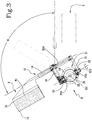
- the body 9 is associated with at least one supporting frame 10 connected to a unit 11 for moving the body 9 configured to rotate about a second axis X11 parallel to the first axis X3 (of the carousel 3) so as to allow a rotation of the body 9 from the position for receiving the group G of filter-bags 1 ( Figures 2 and 3 ) to a position for releasing the group G of filter-bags 1 inside a box 12 ( figure 4 ) and vice versa.
- the transferring unit 8 has the frame 10 for supporting the housing body 9 articulated to the unit 11 for moving the body 9 in such a way as to rotate also about a third axis X10 transversal to the second axis X11 of rotation of the unit 11 for moving the body 9.
- Kinematic means 13 of rotation about the third axis X10 are interposed between the unit 11 for moving the body 9 and the supporting frame 10 and configured to allow a synchronised rotation of the frame 10 about the second X11 and the third X10 axis in such a way as to rotate and orient the group G of filter-bags 1 prior to the arrival of the body 9 in the above-mentioned release position inside the box 12.
- the transfer unit 8 is structured in such a way as to guarantee the rotation designed to allow the housing in the packaging box and simultaneously a correct orientation the groups G of filter-bags 1 immediately before being housed in the packaging box 12.
- the frame 10 comprises a rod 14 for supporting the housing body 9.
- the rod 14 has an axis X14 of longitudinal extension parallel to the third axis X10 of rotation.
- the frame 10 comprises the rod 14 supported by two arms 15 and 16 positioned transversally to the rod 14 and each articulated to the unit 11 for moving the body 9.
- the arms 15, 16 are parallel with each other and articulated in points P15 and P16 different to each other on the unit 11 for moving the body 9 and both intersecting the third axis X10 of rotation.
- the above-mentioned housing body 9 comprises two side walls 9a, 9b and a bottom wall 9c to form a "U" and wherein the open area of the "U" faces towards the operating station 3 (carousel) rotatable about the first axis X3 at its position for receiving the groups G of filter-bags 1 so as to house the group G of filter-bags 1 with a corresponding head 1a in contact with the bottom wall 9c of the housing body 9.
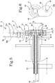
- the movement unit 11 comprises at a first shaft 17 rotating about the second axis X11 and having an end portion with a diameter D1 greater than the diameter D2 of the remaining portion of the first shaft 17.
- the end portion of the first shaft 17 forms an annular flange 18 on which are articulated, on the outer surface, the two arms 15, 16 supporting the bar 14 at points diametrically opposite from each other and intersecting the third axis X10 of rotation.
- the two arms 15 and 16 form a rotary coupling fork on the annular flange 18.
- the movement unit 11 comprises a second shaft 19 positioned coaxially and inside the first shaft 17.
- the second shaft 19 has a free end positioned inside the annular flange 18 of the first shaft 17, forming a tubular chamber, and on which is positioned a first part of the above-mentioned kinematic means 13 of rotation of the frame 10 around the third axis X10.
- the kinematic means 13 comprise a first half-ring gear 20 with teeth having a conical profile made on the free end of the second shaft 19 housed in the tubular chamber formed by the annular flange 18 (gear which therefore forms the first part of the kinematic means).
- the kinematic means 13 comprise a first toothed wheel 21 keyed to an articulation pin 23 in a point P15 of articulation of the supporting arm 15 on the annular flange 18 of the first shaft 17.
- the first toothed wheel 21 is engaged with the first half-ring gear 20 so as to allow the rotation of the supporting arms 15, 16 about the third axis X10 in synchrony with the rotation of the body 9 about the second axis X11.
- the first half ring 20 and the gear wheel 21 form a conical torque which is able to rotate the frame 10 about the annular flange 18 whilst the flange 18 rotates about the second axis X11: this makes it possible to orient the filter-bags 1, whilst they are moved towards the inside of the box 12.
- the movement unit 11 also comprises a third shaft 28 positioned coaxially and inside the second shaft 17 (see Figure 5 ).
- the third shaft 28 has a free end positioned inside the annular flange 18 of the first shaft 17 and on which are positioned movement means 29 configured for controlling the movement of one of the walls 9a, 9b of the body 9, about a fourth axis X9a and in synchrony with the kinematic means 13 (that is, with the conical torque designed for moving the third axis X10), between an inoperative receiving position, wherein the two walls 9a, 9b are parallel to each other, and an operating retaining position, wherein one of the walls 9a is at least partly close to the other wall 9b.
- the movement means 29 comprise a second half-ring gear 30 with teeth having a conical profile connected to the free end of the third shaft 28 housed in the tubular chamber formed by the annular flange 18, and a second toothed wheel 22 keyed to an articulation pin 24 coinciding with a point P16 of articulation of one of the supporting arms 16 on the annular flange 18 of the first shaft 17.
- the second toothed wheel 22 is engaged with the second half-ring gear 30 so as to allow the movement of one of the walls 9a of the body 9, about the fourth axis X9a of rotation in synchrony with the rotation of the body 9 about the second axis X11.
- the second half crown 30 and the gear wheel 22 form a second conical torque which is able to move/rotate a wall 9a of the body 9 whilst the flange 18 rotates about the second axis X11: this makes it possible to retain the group G of filter-bags 1, whilst they are moved towards the inside of the box 12.
- the pin 24 extends along the axis X14 of the arm 16 and the pin 24 is articulated to an arm 32 articulated, in turn, to the wall 9a to allow the book-like movement for opening and closing the wall 9a.
- each arm 15, 16 is articulated to the corresponding pin 23, 24 passing radially through the annular flange 16.
- Each pin 23, 24 is associated with the corresponding gear wheel 21, 22.
- the first shaft 17 has a toothed intermediate portion meshing with a toothed arc 25 formed on an end of a motor-driven operating lever 26.
- the operating lever 26 is articulated to a fixed support 27, at a point P26, so as to execute a pendulum-type movement in both directions about the point P26 of articulation and in such a way as to allow the rotation of the first shaft through a first angle ⁇ about the second axis X11.
- this first angle ⁇ of rotation is substantially equal to 120°.
- the second shaft 19 is connected (kinematically) to and movable in a synchronised fashion with the first shaft 17, allowing rotation of the frame 10 through a second angle about the third axis X10.
- the second angle of rotation is different from the first angle ⁇ of rotation.
- the second angle of rotation is greater than the first angle ⁇ of rotation.
- the second angle of rotation is approximately 180°.
- the preparing and packaging station 4 operates in the following manner.
- the transporting element 2 picks up from the carousel 3 the individual filter-bags 1 and releases them inside the tubular conduit 5 through the end opening 5a aided by the pusher 31 ( Figure 2 ).
- the transport gripper 7 is activated 5 to retain the group G of filter-bags 1 at the top and bottom, whilst the plate 6 releases the bottom of the filter-bags through a movement for opening the relative half-parts or through a radial movement away from the conduit 5 ( Figure 2 ).
- the plate 6 returns upwards to start a new cycle for forming a group G, whilst the gripper 7 slides axially downwards and beyond the bottom of the tubular conduit 5 for moving the group in the housing body 9 waiting in the receiving position ( Figure 2 ).
- the body 9 for housing, receiving and retaining the group G of filter-bags 1 is rotated simultaneously about the second and third axis X11 and X10 so as to orient (that is, rotate by 180°) the filter-bags 1 whilst the group G is transferred by the tubular conduit 5 inside the box 12 for packaging 12 ( Figures 3 and 4 ) in which the group G is released.
- the wall 9a is rotated towards the wall 9b to retain the group G of filter-bags 1 during the double rotation of the body 9.
- a retaining sheet (not illustrated) is inserted between the bottom 9c of the body 9 and the tops 1a of the filter-bags 1 to retain the latter in the box 12 during the return rotation of the housing body 9 towards the tubular conduit 5.
- the preparing and packaging station 4 consists of a limited number of production components, but with a high elasticity thanks to the dual function of the transfer and packaging unit configured to orient the filter-bags simultaneously with their transfer.
- This dual function of the transfer unit actually increases the operational potential of the station, since the orientation is obtained on the entire group of stacked filter-bags rather than the single orientation obtained with the traditional solutions.
- the synchronised movement structure is grouped together in a reduced size and obtains three different movements all synchronised with each other thanks to the system with three coaxial shafts assisted by the pair of conical torques present in the flange.
- This system considerably reduces the overall dimensions of the unit, whilst maintaining a high level of operational precision.
Landscapes
- Engineering & Computer Science (AREA)
- Mechanical Engineering (AREA)
- Supplying Of Containers To The Packaging Station (AREA)
- Packages (AREA)
Claims (11)
- Machine pour former des sachets-filtres (1) contenant des produits d'infusion, incluant au moins un élément de transport (2) configuré pour la saisie, le transport et la libération de sachets-filtres (1) individuels d'un poste de travail (3), servant à former les sachets-filtres (1), tournant autour d'un premier axe (X3), vers un poste (4) servant à préparer et à emballer des groupes (G) de sachets-filtres (1) formés ; le poste de préparation et d'emballage (4) comprenant au moins :- un conduit tubulaire (5) comportant une ouverture d'extrémité (5a) supérieure positionnée en face de l'élément de transport (2) et configurée pour recevoir des sachets-filtres (1) individuels ;- des unités (6, 7) servant à commander la descente des sachets-filtres (1) individuels et à définir le groupe (G) de sachets-filtres à former, mobiles le long du conduit tubulaire (5) ; les unités (6, 7) étant configurées pour former, retenir et transférer le groupe empilé (G) de sachets-filtres (1) au-delà du fond du conduit tubulaire (5) ;- une unité (8), servant à transférer le groupe (G) de sachets-filtres (1), positionné, dans une position de réception, en dessous du conduit tubulaire (5) ; l'unité de transfert (8) comportant un corps (9) servant à loger le groupe (G) de sachets-filtres (1) ; le corps (9) étant associé à au moins un cadre de support (10) relié à une unité (11), servant à déplacer le corps (9), configurée pour tourner autour d'un deuxième axe (X11) parallèle au premier axe (X3) de manière à permettre une rotation du corps (9) de la position servant à recevoir le groupe (G) de sachets-filtres (1) à une position servant à libérer le groupe (G) de sachets-filtres (1) à l'intérieur d'une boîte (12) et vice versa ;l'unité de transfert (8) comportant le cadre (10) servant à supporter le corps de logement (9) articulé à l'unité (11) servant à déplacer le corps (9) de manière à tourner aussi autour d'un troisième axe (X10) transversal au deuxième axe (X11) de rotation de l'unité de déplacement (11) du corps (9) ; des moyens cinématiques (13) de rotation autour du troisième axe (X10) étant interposés entre l'unité (11) servant à déplacer le corps (9) et le cadre de support (10) et configurés pour permettre une rotation synchronisée du cadre (10) autour du deuxième (X11) et du troisième (X10) axe de manière à tourner et à orienter le groupe (G) de sachets-filtres (1) avant l'arrivée du corps (9) en position de libération à l'intérieur de la boîte (12).
- Machine selon la revendication 1, dans laquelle le cadre (10) comprend une tige (14) servant à supporter le corps de logement (9) ; la tige (14) ayant un axe (X14) d'extension longitudinale parallèle au troisième axe (X10) de rotation.
- Machine selon l'une quelconque des revendications précédentes, dans laquelle le corps de logement (9) comprend deux parois latérales (9a, 9b) et une paroi de fond (9c) pour former un « U » et dans laquelle la zone ouverte du « U » est tournée vers le poste de travail (3) pouvant tourner autour du premier axe (X3) en correspondance de sa position pour recevoir les groupes (G) de sachets-filtres (1) de sorte à loger le groupe (G) de sachets-filtres (1) avec une tête (1a) correspondante en contact avec la paroi de fond (9c) du corps de logement (9).
- Machine selon l'une quelconque des revendications précédentes, dans laquelle le cadre (10) comprend une tige (14) supportée par deux bras (15, 16) positionnés transversalement à la tige (14) et chacun articulé à l'unité (11) pour déplacer le corps (9) ; les bras (15, 16) étant parallèles entre eux et articulés en des points (P15, P16) étant différents l'un de l'autre sur l'unité (11) servant à déplacer le corps (9) et tous deux coupant le troisième axe (X10) de rotation.
- Machine selon l'une quelconque des revendications précédentes, dans laquelle l'unité de déplacement (11) comprend au moins un premier arbre (17) tournant autour du deuxième axe (X11) et comportant une partie d'extrémité ayant un diamètre (D1) supérieur au diamètre (02) de la partie restante du premier arbre (17) ; la partie d'extrémité du premier arbre (17) formant une bride annulaire (18) sur laquelle sont articulés, sur la surface extérieure, les deux bras (15, 16) servant à supporter la tige (14) en correspondance de points diamétralement opposés l'un de l'autre et coupant le troisième axe (X10) de rotation.
- Machine selon la revendication 5, dans laquelle l'unité de déplacement (11) comprend un deuxième arbre (19) positionné coaxialement et à l'intérieur du premier arbre (17) ; le deuxième arbre (19) ayant une extrémité libre positionnée à l'intérieur de la bride annulaire (18) du premier arbre (17), formant une chambre tubulaire, et sur laquelle est positionnée une première partie des moyens cinématiques (13) de rotation du cadre (10) autour du troisième axe (X10).
- Machine selon l'une quelconque des revendications 4 à 6, dans laquelle les moyens cinématiques (13) comprennent une première demi-couronne (20), avec des dents ayant un profil conique, réalisée sur l'extrémité libre du deuxième arbre (19) logée dans la chambre tubulaire formée par la bride annulaire (18), et une première roue dentée (21) clavetée sur un axe d'articulation (23) coïncidant avec un point (P15) d'articulation d'un des bras de support (15, 16) sur la bride annulaire (18) du premier arbre (17) ; la première roue dentée (21) se mettant en prise avec la première demi-couronne (20) de manière à permettre la rotation des bras de support (15, 16) autour du troisième axe (X10) de manière synchronisée avec la rotation du corps (9) autour du deuxième axe (X11).
- Machine selon l'une quelconque des revendications 4 à 7, dans laquelle l'unité de déplacement (11) comprend un troisième arbre (28) positionné coaxialement et à l'intérieur du deuxième arbre (17) ; le troisième arbre (28) comportant une extrémité libre positionnée à l'intérieur de la bride annulaire (18) du premier arbre (17), formant une chambre tubulaire, et sur laquelle sont positionnés des moyens de déplacement (29) configurés pour commander le déplacement de l'une des parois (9a, 9b) du corps (9), autour d'un quatrième axe (X9a) et synchrone avec les moyens cinématiques (13), entre une position de réception non fonctionnelle, dans laquelle les deux parois (9a, 9b) sont parallèles l'une à l'autre, et une position de retenue fonctionnelle, dans laquelle l'une des parois (9a) est au moins partiellement à proximité de l'autre paroi (9b).
- Machine selon la revendication 8, dans laquelle les moyens de déplacement (29) comprennent une deuxième demi-couronne (30), avec des dents ayant un profil conique, reliée à l'extrémité libre du troisième arbre (28), logée dans la chambre tubulaire formée par la bride annulaire (18), et une deuxième roue dentée (22) clavetée sur un axe d'articulation (24) coïncidant avec un point (P16) d'articulation de l'un des bras de support (16) sur la bride annulaire (18) du premier arbre (17) ; la deuxième roue dentée (22) se mettant en prise avec la deuxième demi-couronne (30) de manière à permettre le déplacement de l'une des parois (9a, 9b) du corps (9) autour du quatrième axe (X9a) de rotation synchrone avec la rotation du corps (9) autour du deuxième axe (X11).
- Machine selon l'une quelconque des revendications 4 à 9, dans laquelle le premier arbre (17) comporte une partie intermédiaire dentée s'engrenant avec un arc denté (25) formé sur une extrémité d'un levier fonctionnel (26) motorisé ; le levier fonctionnel (26) étant articulé sur un support fixe (27), en correspondance d'un point (P26), de manière à exécuter un déplacement pendulaire dans les deux sens autour du point (P26) d'articulation et de manière à permettre la rotation du premier arbre selon un premier angle (α) autour du deuxième axe (X11).
- Machine selon l'une quelconque des revendications 4 à 10, dans laquelle le deuxième arbre (19) est relié au premier arbre (17) et mobile de manière synchronisée avec celui-ci, permettant la rotation du cadre (10) selon un deuxième angle autour du troisième axe (X10).
Applications Claiming Priority (2)
| Application Number | Priority Date | Filing Date | Title |
|---|---|---|---|
| IT102016000076483A IT201600076483A1 (it) | 2016-07-21 | 2016-07-21 | Macchina per formare sacchetti-filtro con prodotti da infusione. |
| PCT/IB2017/054389 WO2018015913A1 (fr) | 2016-07-21 | 2017-07-20 | Machine pour former des sacs filtrants contenant des produits de perfusion |
Publications (2)
| Publication Number | Publication Date |
|---|---|
| EP3487768A1 EP3487768A1 (fr) | 2019-05-29 |
| EP3487768B1 true EP3487768B1 (fr) | 2020-09-02 |
Family
ID=58159170
Family Applications (1)
| Application Number | Title | Priority Date | Filing Date |
|---|---|---|---|
| EP17761322.1A Active EP3487768B1 (fr) | 2016-07-21 | 2017-07-20 | Machine pour former des sacs filtrants contenant des produits de perfusion |
Country Status (4)
| Country | Link |
|---|---|
| EP (1) | EP3487768B1 (fr) |
| ES (1) | ES2834311T3 (fr) |
| IT (1) | IT201600076483A1 (fr) |
| WO (1) | WO2018015913A1 (fr) |
Cited By (1)
| Publication number | Priority date | Publication date | Assignee | Title |
|---|---|---|---|---|
| EP4037977B1 (fr) * | 2019-09-30 | 2023-11-08 | I.M.A. Industria Macchine Automatiche S.p.A. | Machine à emballer pour réaliser des sacs filtrants comprenant des produits de perfusion |
Family Cites Families (4)
| Publication number | Priority date | Publication date | Assignee | Title |
|---|---|---|---|---|
| IT1281771B1 (it) * | 1995-04-04 | 1998-03-03 | Tecnomeccanica Srl | Apparato per distribuire uniformemente un prodotto incoerente contenuto all'interno di una busta, e macchina di confezionamento |
| IT1320888B1 (it) * | 2000-02-22 | 2003-12-10 | Ima Spa | Metodo per lo scarto di un sacchetto - filtro per prodotti dainfusione in una macchina produttrice e relativo dispositivo attuante |
| ITBO20060422A1 (it) * | 2006-05-31 | 2007-12-01 | Ima Spa | Macchina automatica confezionatrice per la produzione di sacchetti filtro per prodotti da infusione |
| ITBO20110094A1 (it) * | 2011-03-01 | 2012-09-02 | Roberto Conti | Macchina per la produzione di sacchetti - filtro con prodotti da infusione e con busta di sovraincarto |
-
2016
- 2016-07-21 IT IT102016000076483A patent/IT201600076483A1/it unknown
-
2017
- 2017-07-20 WO PCT/IB2017/054389 patent/WO2018015913A1/fr not_active Ceased
- 2017-07-20 ES ES17761322T patent/ES2834311T3/es active Active
- 2017-07-20 EP EP17761322.1A patent/EP3487768B1/fr active Active
Non-Patent Citations (1)
| Title |
|---|
| None * |
Cited By (2)
| Publication number | Priority date | Publication date | Assignee | Title |
|---|---|---|---|---|
| EP4037977B1 (fr) * | 2019-09-30 | 2023-11-08 | I.M.A. Industria Macchine Automatiche S.p.A. | Machine à emballer pour réaliser des sacs filtrants comprenant des produits de perfusion |
| US12054299B2 (en) | 2019-09-30 | 2024-08-06 | I.M.A. Industria Macchine Automatiche S.P.A. | Packaging machine for making filter bags with infusion productions |
Also Published As
| Publication number | Publication date |
|---|---|
| IT201600076483A1 (it) | 2018-01-21 |
| EP3487768A1 (fr) | 2019-05-29 |
| WO2018015913A1 (fr) | 2018-01-25 |
| ES2834311T3 (es) | 2021-06-17 |
Similar Documents
| Publication | Publication Date | Title |
|---|---|---|
| EP3419901B1 (fr) | Machine de formation de sachets filtrants pour produits à infuser | |
| EP3704025B1 (fr) | Machine de formation de sachets-filtres destinés à des produits à infuser | |
| EP2681119B1 (fr) | Machine de production de sachets-filtrants a produits pour infusion et a enveloppe exterieure | |
| EP3414165B1 (fr) | Unité et procédé pour placer des objets dans des boîtes | |
| EP4051596B1 (fr) | Unité de suremballage de sacs filtrants pour produits de perfusion et procédé correspondant | |
| WO2018150334A1 (fr) | Unité et procédé pour placer des objets dans des boîtes | |
| WO2018015913A1 (fr) | Machine pour former des sacs filtrants contenant des produits de perfusion | |
| US20190016486A1 (en) | Unit and method for placing objects in boxes | |
| EP3678945B1 (fr) | Machine de formation de sachets filtrants pour produits à infuser | |
| EP3393915B1 (fr) | Machine de fabrication de sachets-filtres avec station d'empilage. | |
| EP3595975B1 (fr) | Dispositif et procédé de fabrication de sachets-filtres pour produits d'infusion | |
| JP2010280427A (ja) | 包装体搬送装置及び該装置を備えた自動包装機 | |
| EP3649051B1 (fr) | Machine de formation de sachets-filtres pour produits à infuser | |
| WO2024154008A1 (fr) | Machine de production de dosettes avec produits d'extraction | |
| EP3393914B1 (fr) | Machine pour former des sachets de filtre pour produits à infuser avec des stations de pliage |
Legal Events
| Date | Code | Title | Description |
|---|---|---|---|
| STAA | Information on the status of an ep patent application or granted ep patent |
Free format text: STATUS: UNKNOWN |
|
| STAA | Information on the status of an ep patent application or granted ep patent |
Free format text: STATUS: THE INTERNATIONAL PUBLICATION HAS BEEN MADE |
|
| PUAI | Public reference made under article 153(3) epc to a published international application that has entered the european phase |
Free format text: ORIGINAL CODE: 0009012 |
|
| STAA | Information on the status of an ep patent application or granted ep patent |
Free format text: STATUS: REQUEST FOR EXAMINATION WAS MADE |
|
| 17P | Request for examination filed |
Effective date: 20190122 |
|
| AK | Designated contracting states |
Kind code of ref document: A1 Designated state(s): AL AT BE BG CH CY CZ DE DK EE ES FI FR GB GR HR HU IE IS IT LI LT LU LV MC MK MT NL NO PL PT RO RS SE SI SK SM TR |
|
| AX | Request for extension of the european patent |
Extension state: BA ME |
|
| DAV | Request for validation of the european patent (deleted) | ||
| DAX | Request for extension of the european patent (deleted) | ||
| GRAJ | Information related to disapproval of communication of intention to grant by the applicant or resumption of examination proceedings by the epo deleted |
Free format text: ORIGINAL CODE: EPIDOSDIGR1 |
|
| STAA | Information on the status of an ep patent application or granted ep patent |
Free format text: STATUS: GRANT OF PATENT IS INTENDED |
|
| GRAP | Despatch of communication of intention to grant a patent |
Free format text: ORIGINAL CODE: EPIDOSNIGR1 |
|
| INTG | Intention to grant announced |
Effective date: 20200417 |
|
| GRAS | Grant fee paid |
Free format text: ORIGINAL CODE: EPIDOSNIGR3 |
|
| GRAA | (expected) grant |
Free format text: ORIGINAL CODE: 0009210 |
|
| STAA | Information on the status of an ep patent application or granted ep patent |
Free format text: STATUS: THE PATENT HAS BEEN GRANTED |
|
| AK | Designated contracting states |
Kind code of ref document: B1 Designated state(s): AL AT BE BG CH CY CZ DE DK EE ES FI FR GB GR HR HU IE IS IT LI LT LU LV MC MK MT NL NO PL PT RO RS SE SI SK SM TR |
|
| REG | Reference to a national code |
Ref country code: GB Ref legal event code: FG4D |
|
| REG | Reference to a national code |
Ref country code: AT Ref legal event code: REF Ref document number: 1308557 Country of ref document: AT Kind code of ref document: T Effective date: 20200915 Ref country code: CH Ref legal event code: EP |
|
| REG | Reference to a national code |
Ref country code: DE Ref legal event code: R096 Ref document number: 602017022901 Country of ref document: DE |
|
| REG | Reference to a national code |
Ref country code: IE Ref legal event code: FG4D |
|
| REG | Reference to a national code |
Ref country code: LT Ref legal event code: MG4D |
|
| PG25 | Lapsed in a contracting state [announced via postgrant information from national office to epo] |
Ref country code: GR Free format text: LAPSE BECAUSE OF FAILURE TO SUBMIT A TRANSLATION OF THE DESCRIPTION OR TO PAY THE FEE WITHIN THE PRESCRIBED TIME-LIMIT Effective date: 20201203 Ref country code: NO Free format text: LAPSE BECAUSE OF FAILURE TO SUBMIT A TRANSLATION OF THE DESCRIPTION OR TO PAY THE FEE WITHIN THE PRESCRIBED TIME-LIMIT Effective date: 20201202 Ref country code: HR Free format text: LAPSE BECAUSE OF FAILURE TO SUBMIT A TRANSLATION OF THE DESCRIPTION OR TO PAY THE FEE WITHIN THE PRESCRIBED TIME-LIMIT Effective date: 20200902 Ref country code: SE Free format text: LAPSE BECAUSE OF FAILURE TO SUBMIT A TRANSLATION OF THE DESCRIPTION OR TO PAY THE FEE WITHIN THE PRESCRIBED TIME-LIMIT Effective date: 20200902 Ref country code: FI Free format text: LAPSE BECAUSE OF FAILURE TO SUBMIT A TRANSLATION OF THE DESCRIPTION OR TO PAY THE FEE WITHIN THE PRESCRIBED TIME-LIMIT Effective date: 20200902 Ref country code: LT Free format text: LAPSE BECAUSE OF FAILURE TO SUBMIT A TRANSLATION OF THE DESCRIPTION OR TO PAY THE FEE WITHIN THE PRESCRIBED TIME-LIMIT Effective date: 20200902 Ref country code: BG Free format text: LAPSE BECAUSE OF FAILURE TO SUBMIT A TRANSLATION OF THE DESCRIPTION OR TO PAY THE FEE WITHIN THE PRESCRIBED TIME-LIMIT Effective date: 20201202 |
|
| REG | Reference to a national code |
Ref country code: NL Ref legal event code: MP Effective date: 20200902 |
|
| REG | Reference to a national code |
Ref country code: AT Ref legal event code: MK05 Ref document number: 1308557 Country of ref document: AT Kind code of ref document: T Effective date: 20200902 |
|
| PG25 | Lapsed in a contracting state [announced via postgrant information from national office to epo] |
Ref country code: PL Free format text: LAPSE BECAUSE OF FAILURE TO SUBMIT A TRANSLATION OF THE DESCRIPTION OR TO PAY THE FEE WITHIN THE PRESCRIBED TIME-LIMIT Effective date: 20200902 Ref country code: LV Free format text: LAPSE BECAUSE OF FAILURE TO SUBMIT A TRANSLATION OF THE DESCRIPTION OR TO PAY THE FEE WITHIN THE PRESCRIBED TIME-LIMIT Effective date: 20200902 Ref country code: RS Free format text: LAPSE BECAUSE OF FAILURE TO SUBMIT A TRANSLATION OF THE DESCRIPTION OR TO PAY THE FEE WITHIN THE PRESCRIBED TIME-LIMIT Effective date: 20200902 |
|
| PG25 | Lapsed in a contracting state [announced via postgrant information from national office to epo] |
Ref country code: CZ Free format text: LAPSE BECAUSE OF FAILURE TO SUBMIT A TRANSLATION OF THE DESCRIPTION OR TO PAY THE FEE WITHIN THE PRESCRIBED TIME-LIMIT Effective date: 20200902 Ref country code: RO Free format text: LAPSE BECAUSE OF FAILURE TO SUBMIT A TRANSLATION OF THE DESCRIPTION OR TO PAY THE FEE WITHIN THE PRESCRIBED TIME-LIMIT Effective date: 20200902 Ref country code: PT Free format text: LAPSE BECAUSE OF FAILURE TO SUBMIT A TRANSLATION OF THE DESCRIPTION OR TO PAY THE FEE WITHIN THE PRESCRIBED TIME-LIMIT Effective date: 20210104 Ref country code: SM Free format text: LAPSE BECAUSE OF FAILURE TO SUBMIT A TRANSLATION OF THE DESCRIPTION OR TO PAY THE FEE WITHIN THE PRESCRIBED TIME-LIMIT Effective date: 20200902 Ref country code: EE Free format text: LAPSE BECAUSE OF FAILURE TO SUBMIT A TRANSLATION OF THE DESCRIPTION OR TO PAY THE FEE WITHIN THE PRESCRIBED TIME-LIMIT Effective date: 20200902 |
|
| PG25 | Lapsed in a contracting state [announced via postgrant information from national office to epo] |
Ref country code: AL Free format text: LAPSE BECAUSE OF FAILURE TO SUBMIT A TRANSLATION OF THE DESCRIPTION OR TO PAY THE FEE WITHIN THE PRESCRIBED TIME-LIMIT Effective date: 20200902 Ref country code: AT Free format text: LAPSE BECAUSE OF FAILURE TO SUBMIT A TRANSLATION OF THE DESCRIPTION OR TO PAY THE FEE WITHIN THE PRESCRIBED TIME-LIMIT Effective date: 20200902 Ref country code: IS Free format text: LAPSE BECAUSE OF FAILURE TO SUBMIT A TRANSLATION OF THE DESCRIPTION OR TO PAY THE FEE WITHIN THE PRESCRIBED TIME-LIMIT Effective date: 20210102 |
|
| REG | Reference to a national code |
Ref country code: DE Ref legal event code: R097 Ref document number: 602017022901 Country of ref document: DE |
|
| REG | Reference to a national code |
Ref country code: ES Ref legal event code: FG2A Ref document number: 2834311 Country of ref document: ES Kind code of ref document: T3 Effective date: 20210617 |
|
| PG25 | Lapsed in a contracting state [announced via postgrant information from national office to epo] |
Ref country code: SK Free format text: LAPSE BECAUSE OF FAILURE TO SUBMIT A TRANSLATION OF THE DESCRIPTION OR TO PAY THE FEE WITHIN THE PRESCRIBED TIME-LIMIT Effective date: 20200902 |
|
| PLBE | No opposition filed within time limit |
Free format text: ORIGINAL CODE: 0009261 |
|
| STAA | Information on the status of an ep patent application or granted ep patent |
Free format text: STATUS: NO OPPOSITION FILED WITHIN TIME LIMIT |
|
| 26N | No opposition filed |
Effective date: 20210603 |
|
| PG25 | Lapsed in a contracting state [announced via postgrant information from national office to epo] |
Ref country code: SI Free format text: LAPSE BECAUSE OF FAILURE TO SUBMIT A TRANSLATION OF THE DESCRIPTION OR TO PAY THE FEE WITHIN THE PRESCRIBED TIME-LIMIT Effective date: 20200902 Ref country code: DK Free format text: LAPSE BECAUSE OF FAILURE TO SUBMIT A TRANSLATION OF THE DESCRIPTION OR TO PAY THE FEE WITHIN THE PRESCRIBED TIME-LIMIT Effective date: 20200902 |
|
| REG | Reference to a national code |
Ref country code: CH Ref legal event code: PL |
|
| PG25 | Lapsed in a contracting state [announced via postgrant information from national office to epo] |
Ref country code: MC Free format text: LAPSE BECAUSE OF FAILURE TO SUBMIT A TRANSLATION OF THE DESCRIPTION OR TO PAY THE FEE WITHIN THE PRESCRIBED TIME-LIMIT Effective date: 20200902 |
|
| REG | Reference to a national code |
Ref country code: BE Ref legal event code: MM Effective date: 20210731 |
|
| PG25 | Lapsed in a contracting state [announced via postgrant information from national office to epo] |
Ref country code: LI Free format text: LAPSE BECAUSE OF NON-PAYMENT OF DUE FEES Effective date: 20210731 Ref country code: CH Free format text: LAPSE BECAUSE OF NON-PAYMENT OF DUE FEES Effective date: 20210731 |
|
| PG25 | Lapsed in a contracting state [announced via postgrant information from national office to epo] |
Ref country code: LU Free format text: LAPSE BECAUSE OF NON-PAYMENT OF DUE FEES Effective date: 20210720 |
|
| PG25 | Lapsed in a contracting state [announced via postgrant information from national office to epo] |
Ref country code: IE Free format text: LAPSE BECAUSE OF NON-PAYMENT OF DUE FEES Effective date: 20210720 Ref country code: BE Free format text: LAPSE BECAUSE OF NON-PAYMENT OF DUE FEES Effective date: 20210731 |
|
| PG25 | Lapsed in a contracting state [announced via postgrant information from national office to epo] |
Ref country code: NL Free format text: LAPSE BECAUSE OF NON-PAYMENT OF DUE FEES Effective date: 20200923 Ref country code: CY Free format text: LAPSE BECAUSE OF FAILURE TO SUBMIT A TRANSLATION OF THE DESCRIPTION OR TO PAY THE FEE WITHIN THE PRESCRIBED TIME-LIMIT Effective date: 20200902 |
|
| P01 | Opt-out of the competence of the unified patent court (upc) registered |
Effective date: 20230529 |
|
| PG25 | Lapsed in a contracting state [announced via postgrant information from national office to epo] |
Ref country code: HU Free format text: LAPSE BECAUSE OF FAILURE TO SUBMIT A TRANSLATION OF THE DESCRIPTION OR TO PAY THE FEE WITHIN THE PRESCRIBED TIME-LIMIT; INVALID AB INITIO Effective date: 20170720 |
|
| PG25 | Lapsed in a contracting state [announced via postgrant information from national office to epo] |
Ref country code: MK Free format text: LAPSE BECAUSE OF FAILURE TO SUBMIT A TRANSLATION OF THE DESCRIPTION OR TO PAY THE FEE WITHIN THE PRESCRIBED TIME-LIMIT Effective date: 20200902 |
|
| PG25 | Lapsed in a contracting state [announced via postgrant information from national office to epo] |
Ref country code: TR Free format text: LAPSE BECAUSE OF FAILURE TO SUBMIT A TRANSLATION OF THE DESCRIPTION OR TO PAY THE FEE WITHIN THE PRESCRIBED TIME-LIMIT Effective date: 20200902 |
|
| PG25 | Lapsed in a contracting state [announced via postgrant information from national office to epo] |
Ref country code: MT Free format text: LAPSE BECAUSE OF FAILURE TO SUBMIT A TRANSLATION OF THE DESCRIPTION OR TO PAY THE FEE WITHIN THE PRESCRIBED TIME-LIMIT Effective date: 20200902 |
|
| PGFP | Annual fee paid to national office [announced via postgrant information from national office to epo] |
Ref country code: ES Payment date: 20250827 Year of fee payment: 9 |
|
| PGFP | Annual fee paid to national office [announced via postgrant information from national office to epo] |
Ref country code: DE Payment date: 20250723 Year of fee payment: 9 |
|
| PGFP | Annual fee paid to national office [announced via postgrant information from national office to epo] |
Ref country code: IT Payment date: 20250722 Year of fee payment: 9 |
|
| PGFP | Annual fee paid to national office [announced via postgrant information from national office to epo] |
Ref country code: GB Payment date: 20250724 Year of fee payment: 9 |
|
| PGFP | Annual fee paid to national office [announced via postgrant information from national office to epo] |
Ref country code: FR Payment date: 20250717 Year of fee payment: 9 |