EP3487786B1 - Tête de pulvérisation pour un container aérosol - Google Patents
Tête de pulvérisation pour un container aérosol Download PDFInfo
- Publication number
- EP3487786B1 EP3487786B1 EP17737790.0A EP17737790A EP3487786B1 EP 3487786 B1 EP3487786 B1 EP 3487786B1 EP 17737790 A EP17737790 A EP 17737790A EP 3487786 B1 EP3487786 B1 EP 3487786B1
- Authority
- EP
- European Patent Office
- Prior art keywords
- actuating element
- spray cap
- shell part
- spray
- connection
- Prior art date
- Legal status (The legal status is an assumption and is not a legal conclusion. Google has not performed a legal analysis and makes no representation as to the accuracy of the status listed.)
- Active
Links
Images
Classifications
-
- B—PERFORMING OPERATIONS; TRANSPORTING
- B65—CONVEYING; PACKING; STORING; HANDLING THIN OR FILAMENTARY MATERIAL
- B65D—CONTAINERS FOR STORAGE OR TRANSPORT OF ARTICLES OR MATERIALS, e.g. BAGS, BARRELS, BOTTLES, BOXES, CANS, CARTONS, CRATES, DRUMS, JARS, TANKS, HOPPERS, FORWARDING CONTAINERS; ACCESSORIES, CLOSURES, OR FITTINGS THEREFOR; PACKAGING ELEMENTS; PACKAGES
- B65D83/00—Containers or packages with special means for dispensing contents
- B65D83/14—Containers for dispensing liquid or semi-liquid contents by internal gaseous pressure, i.e. aerosol containers comprising propellant
- B65D83/16—Actuating means
- B65D83/22—Actuating means with means to disable actuation
- B65D83/224—Tamper-indicating means obstructing initial actuation
- B65D83/228—Tamper-indicating means obstructing initial actuation consisting of a rupturable connection between actuator element and actuator cap or skirt, e.g. tear strips or bridges
-
- B—PERFORMING OPERATIONS; TRANSPORTING
- B65—CONVEYING; PACKING; STORING; HANDLING THIN OR FILAMENTARY MATERIAL
- B65D—CONTAINERS FOR STORAGE OR TRANSPORT OF ARTICLES OR MATERIALS, e.g. BAGS, BARRELS, BOTTLES, BOXES, CANS, CARTONS, CRATES, DRUMS, JARS, TANKS, HOPPERS, FORWARDING CONTAINERS; ACCESSORIES, CLOSURES, OR FITTINGS THEREFOR; PACKAGING ELEMENTS; PACKAGES
- B65D83/00—Containers or packages with special means for dispensing contents
- B65D83/14—Containers for dispensing liquid or semi-liquid contents by internal gaseous pressure, i.e. aerosol containers comprising propellant
- B65D83/16—Actuating means
- B65D83/20—Actuator caps
- B65D83/206—Actuator caps comprising cantilevered actuating elements, e.g. levers pivoting about living hinges
Definitions
- the invention relates to a spray cap for attachment to an aerosol pressurized gas container with a safety device against unintentional folding up of the actuating element.
- Compressed gas packs are usually made up of a spray can with a spray line that ends in the can lid and a spray valve that is located in, in front of or behind the spray line. This valve is closed in the “storage state” and can be opened against a restoring force using an actuating element that is accessible from the outside to remove the contents of the pack.
- the usual spray cans are provided with a protective cover.
- Spray cans are usually made of metal or plastic, whereby the spray head, parts of the spray head, the actuating element and the protective cover can also be made of plastic (mainly polypropylene).
- plastic mainly polypropylene
- the contents to be sprayed are filled into the metal or plastic can under excess pressure and are released as mist (aerosol) or foam when the valve is operated.
- Spray cans or pressurized gas packs are available on the market for many different products; examples include products from the cosmetics sector such as hairspray, deodorants, shaving foam, but also spray adhesives, room fresheners, insect sprays, cleaning products and much more.
- the EP 0 323 874 A1 shows a container provided with a protective cap for spraying products.
- the product is released here by absorption and reproduction of the product via an absorbent means which essentially has the shape of a disk.
- An embodiment of the container is also designed in such a way that the means for actuating the spraying device from the outside of the protective bell has a deformable area of the protective bell.
- the EN 102009007813 discloses a spray cap for attachment to a compressed gas pack comprising a casing part and an actuating element with a nozzle opening, characterized in that a covering device is movably connected to the casing part, wherein the connection between the covering device and the outer casing allows a folding movement and wherein the covering device covers the actuating element in the closed state (closed position) and at least partially overlies and/or overlaps the upper edge of the casing part.
- the DE 27 52 563 A1 discloses a spray cap assembly for an aerosol container or for a pump-equipped container in which an actuating button is inserted into the cap from below and a resilient tongue on the button then snaps onto a stop in the cap and then engages a recess behind the stop to hold the button in place.
- a projection which frictionally engages a notch in the wall of the cap to hold the button in the correct orientation for attachment to the container.
- the object of the invention is to provide a spray system in the form of a spray cap for aerosol pressure gas bottles, which does not have the aforementioned disadvantages of the prior art.
- a spray cap is to be provided in which a mechanical locking of the actuating element relative to the casing part takes place during the manufacturing process, i.e. injection molding.
- a spray cap according to the invention for attaching to an aerosol pressurized gas pack, as set out in the main claim.
- the subclaims describe an advantageous embodiment of this spray cap and a package with this spray cap.
- the invention relates according to the main claim to a spray cap for attachment to a compressed gas pack, whereby the spray cap and compressed gas pack form a spray system, comprising a casing part with an actuating element hinged to the casing part and a protective cardboard covering the casing part, characterized in that the actuating element has at least one small projection which extends in at least a corresponding opening in the casing part, which prevents the actuating element from opening.
- pressurized gas packs in particular aerosol pressurized gas packs, are understood to mean containers that are able to hold a filling material and a propellant, whereby the filling material and propellant can be present together or separately, e.g. in separate chambers within the container (e.g. bag-in-can system).
- the container is closed by a lid element that is flanged or pressed all the way around the container wall so that an annular bead area is formed.
- the lid element has a valve in the center of its surface that serves to dispense the aerosol or the filling material.
- the spray cap according to the invention has a more or less cylindrical casing part which is attached to the annular bead of the aerosol container by means of locking elements or equivalent aids.
- An actuating element is arranged in the center of the casing part which, in conjunction with the valve of the compressed gas pack, represents the triggering device and has at least one channel inside which guides the aerosol or filling material emerging from the valve to the nozzle opening, from where it is released into the environment.
- the actuating element is connected to the casing part in such a way that the actuating element can be folded into the casing part.
- the connection is preferably designed as a hinge or foil hinge.
- the actuating element also has an actuating surface on the side facing away from the valve connection. If pressure is exerted on the actuating surface, a vertical displacement (folding in) of the actuating element occurs within the casing part, thus leading to the opening of the valve and thus to the discharge of the filling material from the nozzle opening.
- the casing part may be perforated so that the aerosol or filling product dispensing is not obstructed.
- the spray cap according to the invention has a covering device (protective cap) which, when closed, covers the actuating element (closed position) and at least partially overlaps or engages over the upper edge of the casing part.
- the covering device is connected to the casing part in such a way that the covering device can be removed with little effort, but does not come off by itself.
- the cover When closed, the cover protects against accidental activation of the actuating element. When the cover is removed, the actuating element can be pressed without any problem.
- the projection on the actuating element is opposite the connection point between the actuating element and the casing part. It is particularly advantageous to dimension the projection in such a way that it does not protrude from the corresponding opening in the casing part or protrude beyond it.
- the actuating element covering device is connected to the casing part in a further region, whereby this connection has the function of a tamper-evident closure and only exists until the first use.
- connection of the actuating element and the casing part in such a way that the connection builds up a spring tension, so that the covering device is pulled in the closed and/or opened position and a small counterforce must be overcome when folding from the rest positions.
- the actuating surface of the actuating element of the spray cap does not have a smooth surface, but is structured, in particular by knobs, notches, grooves, notches or the like.
- the actuating surface as a whole or only the connection between the actuating surface and the casing part consists of a thermoplastic elastomer, in particular of PE, EPDM, silicone and/or polyurethane.
- a particularly advantageous embodiment of the spray system according to the invention is characterized in that the spray cap is manufactured using a two-component injection molding process. It is also possible to overmold a part previously placed in the injection molding tool with a second component.
- the spray cap is made of a thermoplastic material, preferably PE or PP. PS, SAN, ABS, PA, POM or other mass-produced plastics can also be used.
- the actuating surface is made of a soft synthetic material with high resilience, for example a thermoplastic elastomer, preferably made from PE or EPDM. Silicones or polyurethanes can also be used.
- connection between the spray cap and the gas pack in the area of the neck can be designed in the form of a flanged edge on the gas pack, over which the spray cap snaps in.
- a variant of this is when the spray cap snaps into place due to a projection or groove on the gas pack.
- the spray mechanisms known to date can be used under the spray cap, so that existing production systems do not have to be converted for this purpose.
- the common spray cans with a disk valve can be used as a pressurized gas pack in conjunction with the spray cap according to the invention.
- the systems used to mount the spray cap on the aerosol container can apply greater forces to press/bounce when mounting spray caps according to the invention without running the risk of the actuating element folding out of the casing part and thus not sitting on the valve.
- the invention makes it possible to achieve higher cycle rates during assembly, which reduces assembly costs. Material costs are not increased with spray caps according to the invention, since the additional material for the projection on the actuating element can be offset by the saving in material for the corresponding opening in the casing part.
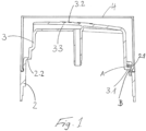
- FIG 1 shows schematically a possible embodiment of a spray cap 1 according to the invention.
- An actuating element 3 is pivotably connected to a cylindrical casing part 2 via a foil hinge 2.2.
- the actuating element also has a security bar (not visible) which serves as a tamper-evident closure.
- the actuating element 3 has a projection 3.1 on the side opposite the hinge 2.2.
- the projection 3.1 is dimensioned such that it protrudes into a corresponding opening 2.1 in the casing part 2 ( Figure 1a) or protrudes up to the casing part ( Figure 1b).
- the opening 2.1 is dimensioned such that there is only a small distance between the top of projection 3.1 and the upper edge of the opening when no force is exerted on the actuating surface 3.2 (resting state).
- the distance A between the upper edge and the top is advantageously less than 1 mm in the load-free state.
- the actuating element 3 If a force acts on the actuating surface (spray state), the actuating element 3 is pivoted into the casing part 2. In this position, the underside of the projection 3.1 must not touch the lower edge of the opening 2.1 or be blocked by it. It is advantageous to maintain a distance B of 0.2 to 2 mm between the underside and the lower edge.
- the projection 3.1 prevents the actuating element from folding up during assembly, as the movement is prevented by the projection hitting the edge of the opening 2.1. At the same time, the actuating element is free to move for the spraying process.
Landscapes
- Chemical & Material Sciences (AREA)
- Dispersion Chemistry (AREA)
- Engineering & Computer Science (AREA)
- Mechanical Engineering (AREA)
- Containers And Packaging Bodies Having A Special Means To Remove Contents (AREA)
Claims (10)
- Capuchon de pulvérisation (1) destiné à être placé sur un emballage de gaz comprimé, ledit capuchon de pulvérisation comportant- une partie d'enveloppe (2) et- un élément d'actionnement (3) pourvu d'une surface d'actionnement (3.2) et destiné à déclencher le mécanisme de pulvérisation,la partie d'enveloppe (2) et l'élément d'actionnement (3) étant reliés de manière mobile etla liaison entre l'élément d'actionnement (3) et la partie d'enveloppe (2) permettant un mouvement de pliage, caractérisé en ce que- la partie d'enveloppe (2) comporte un passage ou une ouverture (2.1) dans sa périphérie, et- l'élément d'actionnement comporte une saillie (3.1) qui est disposée à distance pour relier la partie d'enveloppe et l'élément d'actionnement,la saillie (3.1) passant à travers le passage ou l'ouverture (2.1) de la partie d'enveloppe etle bord du passage ou de l'ouverture (2.1) ne venant pas en contact avec la saillie à l'état non chargé de l'élément d'actionnement, et la liaison entre la partie d'enveloppe et l'élément d'actionnement étant conçue sous la forme d'une charnière ou d'une charnière pelliculaire (2.2).
- Capuchon de pulvérisation (1) selon la revendication 1, caractérisé en ce que le capuchon de pulvérisation comporte un capuchon de protection amovible (4).
- Capuchon de pulvérisation (1) selon la revendication 1, caractérisé en ce que l'élément d'actionnement comporte un conduit (3.3) pourvu d'une ouverture de buse.
- Capuchon de pulvérisation (1) selon l'une au moins des revendications précédentes, caractérisé en ce que la saillie (3.1) est située en face du point de liaison (2.2) de l'élément d'actionnement (3) à la partie d'enveloppe (2).
- Capuchon de pulvérisation (1) selon l'une au moins des revendications précédentes, caractérisé en ce que l'élément d'actionnement (3) est relié à la partie d'enveloppe (2) dans une autre zone par le biais d'une nervure fixe, cette liaison ayant la fonction d'une fermeture d'inviolabilité et n'étant là que jusqu'à la première utilisation.
- Capuchon de pulvérisation (1) selon l'une au moins des revendications précédentes, caractérisé en ce que la liaison entre l'élément d'actionnement (3) et la partie d'enveloppe (2) est conçue de manière à former une tension à ressort de sorte que l'élément d'actionnement est tiré dans la position fermée et/ou ouverte et, lors du pivotement à partir des positions de repos et/ou de la position ouverte, il est nécessaire de surmonter une petite force antagoniste.
- Capuchon de pulvérisation (1) selon l'une au moins des revendications précédentes, caractérisé en ce que l'élément d'actionnement (3) est structuré, notamment par des boutons, des crans, des rainures, des encoches ou analogues.
- Capuchon de pulvérisation (1) selon l'une des revendications précédentes, caractérisé en ce que le capuchon de pulvérisation est en une matière thermoplastique, notamment PE, PP, PS, SAN, ABS, PA et/ou POM.
- Capuchon de pulvérisation (1) selon l'une des revendications précédentes, caractérisé en ce que la surface d'actionnement (3.2) est en élastomère thermoplastique, notamment PE, EPDM, silicone et/ou polyuréthane, en totalité ou uniquement dans la liaison entre la surface d'actionnement et la partie d'enveloppe.
- Capuchon de pulvérisation (1) selon l'une des revendications précédentes, caractérisé en ce que le capuchon de pulvérisation est réalisé selon un procédé de moulage par injection à deux composants.
Applications Claiming Priority (2)
| Application Number | Priority Date | Filing Date | Title |
|---|---|---|---|
| DE102016008785.4A DE102016008785A1 (de) | 2016-07-22 | 2016-07-22 | Sprühkappe für Aerosoldruckgaspackungen |
| PCT/EP2017/067321 WO2018015203A1 (fr) | 2016-07-22 | 2017-07-11 | Capuchon de pulvérisation pour bombes aérosol |
Publications (3)
| Publication Number | Publication Date |
|---|---|
| EP3487786A1 EP3487786A1 (fr) | 2019-05-29 |
| EP3487786B1 true EP3487786B1 (fr) | 2024-09-11 |
| EP3487786C0 EP3487786C0 (fr) | 2024-09-11 |
Family
ID=59315624
Family Applications (1)
| Application Number | Title | Priority Date | Filing Date |
|---|---|---|---|
| EP17737790.0A Active EP3487786B1 (fr) | 2016-07-22 | 2017-07-11 | Tête de pulvérisation pour un container aérosol |
Country Status (3)
| Country | Link |
|---|---|
| EP (1) | EP3487786B1 (fr) |
| DE (1) | DE102016008785A1 (fr) |
| WO (1) | WO2018015203A1 (fr) |
Families Citing this family (1)
| Publication number | Priority date | Publication date | Assignee | Title |
|---|---|---|---|---|
| DE102024107206A1 (de) | 2024-03-13 | 2025-09-18 | Gábor Fazekas | Adapter |
Citations (2)
| Publication number | Priority date | Publication date | Assignee | Title |
|---|---|---|---|---|
| DE2205929A1 (de) * | 1971-02-09 | 1972-08-24 | Kurt Schwarzkopf Gesellschaft mbH & Co , Innsbruck (Osterreich) | Verschluß fur den Sprühkopf bzw das Spruhventil einer Sprühdose od dgl |
| EP0402636A1 (fr) * | 1989-06-16 | 1990-12-19 | Wella Aktiengesellschaft | Dispositif composé d'un réservoir et d'un levier de manoeuvre agissant sur une pompe d'atomiseur |
Family Cites Families (12)
| Publication number | Priority date | Publication date | Assignee | Title |
|---|---|---|---|---|
| FR2225929A5 (fr) * | 1973-04-13 | 1974-11-08 | Reboul Sa Sofra | |
| FR2401703A1 (fr) * | 1977-09-06 | 1979-03-30 | Aerosol Inventions Dev | Tete de pulverisation |
| FR2625730B1 (fr) | 1988-01-08 | 1990-09-14 | Douwe Egberts Tabaksfab | Dispositif formant capuchon protecteur d'un dispositif de stockage et de pulverisation de produits destines a etre distribues dans l'atmosphere tels que les parfums et insecticides, et dispositif de stockage et de pulverisation pourvu d'un tel dispositif formant capuchon protecteur |
| US5649645A (en) * | 1995-02-15 | 1997-07-22 | S. C. Johnson & Son, Inc. | Overcap sprayer assembly |
| US5791524A (en) * | 1997-05-12 | 1998-08-11 | S. C. Johnson & Son, Inc. | Total release actuator for an aerosol can |
| JP2007001583A (ja) * | 2005-06-21 | 2007-01-11 | Maruichi Valve Co Ltd | エアゾール容器用噴射機構及びエアゾール噴射装置 |
| FR2890055B1 (fr) * | 2005-08-25 | 2007-09-28 | Oreal | Ensemble de conditionnement et de distribution d'un produit |
| JP4798616B2 (ja) * | 2006-04-28 | 2011-10-19 | 株式会社吉野工業所 | ガス抜き可能なエアゾール容器 |
| DE102009007813A1 (de) | 2009-02-06 | 2010-08-12 | Beiersdorf Ag | Sicherheitssprühkappe für Druckgaspackungen |
| FR2957590B1 (fr) * | 2010-03-22 | 2014-04-25 | Lindal France Sas | Diffuseur a gachette |
| DE102014016261A1 (de) * | 2014-10-31 | 2016-05-04 | Beiersdorf Ag | Bevorratungseinrichtung und Verfahren zur Produktentnahme |
| FR3035380B3 (fr) * | 2015-04-24 | 2017-05-12 | Lindal France | Tete de distribution pour recipient aerosol munie de moyens de blocage |
-
2016
- 2016-07-22 DE DE102016008785.4A patent/DE102016008785A1/de not_active Withdrawn
-
2017
- 2017-07-11 WO PCT/EP2017/067321 patent/WO2018015203A1/fr not_active Ceased
- 2017-07-11 EP EP17737790.0A patent/EP3487786B1/fr active Active
Patent Citations (2)
| Publication number | Priority date | Publication date | Assignee | Title |
|---|---|---|---|---|
| DE2205929A1 (de) * | 1971-02-09 | 1972-08-24 | Kurt Schwarzkopf Gesellschaft mbH & Co , Innsbruck (Osterreich) | Verschluß fur den Sprühkopf bzw das Spruhventil einer Sprühdose od dgl |
| EP0402636A1 (fr) * | 1989-06-16 | 1990-12-19 | Wella Aktiengesellschaft | Dispositif composé d'un réservoir et d'un levier de manoeuvre agissant sur une pompe d'atomiseur |
Also Published As
| Publication number | Publication date |
|---|---|
| WO2018015203A1 (fr) | 2018-01-25 |
| EP3487786A1 (fr) | 2019-05-29 |
| DE102016008785A1 (de) | 2018-01-25 |
| EP3487786C0 (fr) | 2024-09-11 |
Similar Documents
| Publication | Publication Date | Title |
|---|---|---|
| DE60301829T2 (de) | Ausgabevorrichtung für einen Behälter mit einem Ventil | |
| EP1513426B1 (fr) | Tete de diffusion dotee d'une valve d'arret | |
| DE69701474T2 (de) | Verschlussmembran | |
| EP2481484B1 (fr) | Dispositif de dépôt | |
| DE60018051T2 (de) | Zusammendrückbarer behälter für flüssiges produktmuster | |
| DE69932163T2 (de) | Ausgabeeinrichtung mit aufreissbarer membran, die zwei produkte voneinander trennt | |
| DE102004010845B3 (de) | Verschluß für einen fließfähiges Gut enthaltenden Behälter | |
| DE69930246T2 (de) | Durch klappelemente gehaltenes druckbetätigbares ventil | |
| EP2723650B1 (fr) | Dispositif de fermeture remplissable permettant de declancher le vidage d'une capsule | |
| DE2739893A1 (de) | Zusammendrueckbare flasche aus elastisch verformbarem material | |
| EP0551146B1 (fr) | Tête de pulvérisateur pour distribuer de la mousse | |
| EP0097972A1 (fr) | Dispositif distributeur de produits pâteux | |
| DE1297547B (de) | Garantieverschluss aus Kunststoff fuer Behaelter | |
| DE102009030627A1 (de) | Ventil und Abgabevorrichtung | |
| EP2627574A1 (fr) | Fermeture en matière plastique dotée d'une capsule pour l'émission de substances actives | |
| DE102018003741A1 (de) | Ventilanordnung und Abgabevorrichtung | |
| EP4461419A1 (fr) | Tête de distribution et distributeur | |
| EP3487786B1 (fr) | Tête de pulvérisation pour un container aérosol | |
| DE602004006189T2 (de) | Baueinheit zur Verpackung und zur Ausgabe eines flüssigen Produkts | |
| EP1309500B1 (fr) | Bouchon atomiseur pour emballages d'aerosol a gaz sous pression | |
| DE102005060167B4 (de) | Abgabevorrichtung | |
| EP0868360A1 (fr) | Capuchon de fermeture | |
| DE102004036004B4 (de) | Behälter mit einem Sprühknopf und einem elastischen Düsenverschlusselement | |
| EP3487785A1 (fr) | Capuchon de pulvérisation pour bombes aérosol | |
| DE29706456U1 (de) | Verschluß für Flaschen o.dgl. |
Legal Events
| Date | Code | Title | Description |
|---|---|---|---|
| STAA | Information on the status of an ep patent application or granted ep patent |
Free format text: STATUS: UNKNOWN |
|
| STAA | Information on the status of an ep patent application or granted ep patent |
Free format text: STATUS: THE INTERNATIONAL PUBLICATION HAS BEEN MADE |
|
| PUAI | Public reference made under article 153(3) epc to a published international application that has entered the european phase |
Free format text: ORIGINAL CODE: 0009012 |
|
| STAA | Information on the status of an ep patent application or granted ep patent |
Free format text: STATUS: REQUEST FOR EXAMINATION WAS MADE |
|
| 17P | Request for examination filed |
Effective date: 20190222 |
|
| AK | Designated contracting states |
Kind code of ref document: A1 Designated state(s): AL AT BE BG CH CY CZ DE DK EE ES FI FR GB GR HR HU IE IS IT LI LT LU LV MC MK MT NL NO PL PT RO RS SE SI SK SM TR |
|
| AX | Request for extension of the european patent |
Extension state: BA ME |
|
| DAV | Request for validation of the european patent (deleted) | ||
| DAX | Request for extension of the european patent (deleted) | ||
| STAA | Information on the status of an ep patent application or granted ep patent |
Free format text: STATUS: EXAMINATION IS IN PROGRESS |
|
| 17Q | First examination report despatched |
Effective date: 20200330 |
|
| RAP3 | Party data changed (applicant data changed or rights of an application transferred) |
Owner name: BEIERSDORF AG |
|
| RAP3 | Party data changed (applicant data changed or rights of an application transferred) |
Owner name: BEIERSDORF AG |
|
| GRAP | Despatch of communication of intention to grant a patent |
Free format text: ORIGINAL CODE: EPIDOSNIGR1 |
|
| STAA | Information on the status of an ep patent application or granted ep patent |
Free format text: STATUS: GRANT OF PATENT IS INTENDED |
|
| INTG | Intention to grant announced |
Effective date: 20240312 |
|
| GRAS | Grant fee paid |
Free format text: ORIGINAL CODE: EPIDOSNIGR3 |
|
| GRAA | (expected) grant |
Free format text: ORIGINAL CODE: 0009210 |
|
| STAA | Information on the status of an ep patent application or granted ep patent |
Free format text: STATUS: THE PATENT HAS BEEN GRANTED |
|
| AK | Designated contracting states |
Kind code of ref document: B1 Designated state(s): AL AT BE BG CH CY CZ DE DK EE ES FI FR GB GR HR HU IE IS IT LI LT LU LV MC MK MT NL NO PL PT RO RS SE SI SK SM TR |
|
| REG | Reference to a national code |
Ref country code: GB Ref legal event code: FG4D Free format text: NOT ENGLISH |
|
| REG | Reference to a national code |
Ref country code: CH Ref legal event code: EP |
|
| REG | Reference to a national code |
Ref country code: DE Ref legal event code: R096 Ref document number: 502017016426 Country of ref document: DE |
|
| REG | Reference to a national code |
Ref country code: IE Ref legal event code: FG4D Free format text: LANGUAGE OF EP DOCUMENT: GERMAN |
|
| U01 | Request for unitary effect filed |
Effective date: 20240911 |
|
| U07 | Unitary effect registered |
Designated state(s): AT BE BG DE DK EE FI FR IT LT LU LV MT NL PT RO SE SI Effective date: 20240930 |
|
| PG25 | Lapsed in a contracting state [announced via postgrant information from national office to epo] |
Ref country code: NO Free format text: LAPSE BECAUSE OF FAILURE TO SUBMIT A TRANSLATION OF THE DESCRIPTION OR TO PAY THE FEE WITHIN THE PRESCRIBED TIME-LIMIT Effective date: 20241211 |
|
| PG25 | Lapsed in a contracting state [announced via postgrant information from national office to epo] |
Ref country code: GR Free format text: LAPSE BECAUSE OF FAILURE TO SUBMIT A TRANSLATION OF THE DESCRIPTION OR TO PAY THE FEE WITHIN THE PRESCRIBED TIME-LIMIT Effective date: 20241212 |
|
| PG25 | Lapsed in a contracting state [announced via postgrant information from national office to epo] |
Ref country code: HR Free format text: LAPSE BECAUSE OF FAILURE TO SUBMIT A TRANSLATION OF THE DESCRIPTION OR TO PAY THE FEE WITHIN THE PRESCRIBED TIME-LIMIT Effective date: 20240911 |
|
| PG25 | Lapsed in a contracting state [announced via postgrant information from national office to epo] |
Ref country code: ES Free format text: LAPSE BECAUSE OF FAILURE TO SUBMIT A TRANSLATION OF THE DESCRIPTION OR TO PAY THE FEE WITHIN THE PRESCRIBED TIME-LIMIT Effective date: 20240911 Ref country code: RS Free format text: LAPSE BECAUSE OF FAILURE TO SUBMIT A TRANSLATION OF THE DESCRIPTION OR TO PAY THE FEE WITHIN THE PRESCRIBED TIME-LIMIT Effective date: 20241211 |
|
| PG25 | Lapsed in a contracting state [announced via postgrant information from national office to epo] |
Ref country code: RS Free format text: LAPSE BECAUSE OF FAILURE TO SUBMIT A TRANSLATION OF THE DESCRIPTION OR TO PAY THE FEE WITHIN THE PRESCRIBED TIME-LIMIT Effective date: 20241211 Ref country code: NO Free format text: LAPSE BECAUSE OF FAILURE TO SUBMIT A TRANSLATION OF THE DESCRIPTION OR TO PAY THE FEE WITHIN THE PRESCRIBED TIME-LIMIT Effective date: 20241211 Ref country code: HR Free format text: LAPSE BECAUSE OF FAILURE TO SUBMIT A TRANSLATION OF THE DESCRIPTION OR TO PAY THE FEE WITHIN THE PRESCRIBED TIME-LIMIT Effective date: 20240911 Ref country code: GR Free format text: LAPSE BECAUSE OF FAILURE TO SUBMIT A TRANSLATION OF THE DESCRIPTION OR TO PAY THE FEE WITHIN THE PRESCRIBED TIME-LIMIT Effective date: 20241212 Ref country code: ES Free format text: LAPSE BECAUSE OF FAILURE TO SUBMIT A TRANSLATION OF THE DESCRIPTION OR TO PAY THE FEE WITHIN THE PRESCRIBED TIME-LIMIT Effective date: 20240911 |
|
| PG25 | Lapsed in a contracting state [announced via postgrant information from national office to epo] |
Ref country code: IS Free format text: LAPSE BECAUSE OF FAILURE TO SUBMIT A TRANSLATION OF THE DESCRIPTION OR TO PAY THE FEE WITHIN THE PRESCRIBED TIME-LIMIT Effective date: 20250111 |
|
| PG25 | Lapsed in a contracting state [announced via postgrant information from national office to epo] |
Ref country code: SM Free format text: LAPSE BECAUSE OF FAILURE TO SUBMIT A TRANSLATION OF THE DESCRIPTION OR TO PAY THE FEE WITHIN THE PRESCRIBED TIME-LIMIT Effective date: 20240911 |
|
| PG25 | Lapsed in a contracting state [announced via postgrant information from national office to epo] |
Ref country code: CZ Free format text: LAPSE BECAUSE OF FAILURE TO SUBMIT A TRANSLATION OF THE DESCRIPTION OR TO PAY THE FEE WITHIN THE PRESCRIBED TIME-LIMIT Effective date: 20240911 Ref country code: PL Free format text: LAPSE BECAUSE OF FAILURE TO SUBMIT A TRANSLATION OF THE DESCRIPTION OR TO PAY THE FEE WITHIN THE PRESCRIBED TIME-LIMIT Effective date: 20240911 |
|
| PG25 | Lapsed in a contracting state [announced via postgrant information from national office to epo] |
Ref country code: SK Free format text: LAPSE BECAUSE OF FAILURE TO SUBMIT A TRANSLATION OF THE DESCRIPTION OR TO PAY THE FEE WITHIN THE PRESCRIBED TIME-LIMIT Effective date: 20240911 |
|
| PLBE | No opposition filed within time limit |
Free format text: ORIGINAL CODE: 0009261 |
|
| STAA | Information on the status of an ep patent application or granted ep patent |
Free format text: STATUS: NO OPPOSITION FILED WITHIN TIME LIMIT |
|
| 26N | No opposition filed |
Effective date: 20250612 |
|
| U20 | Renewal fee for the european patent with unitary effect paid |
Year of fee payment: 9 Effective date: 20250731 |
|
| REG | Reference to a national code |
Ref country code: CH Ref legal event code: H13 Free format text: ST27 STATUS EVENT CODE: U-0-0-H10-H13 (AS PROVIDED BY THE NATIONAL OFFICE) Effective date: 20260224 |
|
| GBPC | Gb: european patent ceased through non-payment of renewal fee |
Effective date: 20250711 |
|
| PG25 | Lapsed in a contracting state [announced via postgrant information from national office to epo] |
Ref country code: GB Free format text: LAPSE BECAUSE OF NON-PAYMENT OF DUE FEES Effective date: 20250711 |