EP3488101B1 - Agencement de régulation de débit pour pale de rotor d'éolienne - Google Patents
Agencement de régulation de débit pour pale de rotor d'éolienne Download PDFInfo
- Publication number
- EP3488101B1 EP3488101B1 EP17717135.2A EP17717135A EP3488101B1 EP 3488101 B1 EP3488101 B1 EP 3488101B1 EP 17717135 A EP17717135 A EP 17717135A EP 3488101 B1 EP3488101 B1 EP 3488101B1
- Authority
- EP
- European Patent Office
- Prior art keywords
- rotor blade
- aerodynamic device
- configuration
- flow regulating
- regulating unit
- Prior art date
- Legal status (The legal status is an assumption and is not a legal conclusion. Google has not performed a legal analysis and makes no representation as to the accuracy of the status listed.)
- Active
Links
Images



Classifications
-
- F—MECHANICAL ENGINEERING; LIGHTING; HEATING; WEAPONS; BLASTING
- F03—MACHINES OR ENGINES FOR LIQUIDS; WIND, SPRING, OR WEIGHT MOTORS; PRODUCING MECHANICAL POWER OR A REACTIVE PROPULSIVE THRUST, NOT OTHERWISE PROVIDED FOR
- F03D—WIND MOTORS
- F03D7/00—Controlling wind motors
- F03D7/02—Controlling wind motors the wind motors having rotation axis substantially parallel to the air flow entering the rotor
- F03D7/022—Adjusting aerodynamic properties of the blades
- F03D7/0232—Adjusting aerodynamic properties of the blades with flaps or slats
-
- F—MECHANICAL ENGINEERING; LIGHTING; HEATING; WEAPONS; BLASTING
- F03—MACHINES OR ENGINES FOR LIQUIDS; WIND, SPRING, OR WEIGHT MOTORS; PRODUCING MECHANICAL POWER OR A REACTIVE PROPULSIVE THRUST, NOT OTHERWISE PROVIDED FOR
- F03D—WIND MOTORS
- F03D1/00—Wind motors with rotation axis substantially parallel to the air flow entering the rotor
- F03D1/06—Rotors
- F03D1/065—Rotors characterised by their construction elements
- F03D1/0675—Rotors characterised by their construction elements of the blades
-
- F—MECHANICAL ENGINEERING; LIGHTING; HEATING; WEAPONS; BLASTING
- F03—MACHINES OR ENGINES FOR LIQUIDS; WIND, SPRING, OR WEIGHT MOTORS; PRODUCING MECHANICAL POWER OR A REACTIVE PROPULSIVE THRUST, NOT OTHERWISE PROVIDED FOR
- F03D—WIND MOTORS
- F03D7/00—Controlling wind motors
- F03D7/02—Controlling wind motors the wind motors having rotation axis substantially parallel to the air flow entering the rotor
- F03D7/022—Adjusting aerodynamic properties of the blades
-
- F—MECHANICAL ENGINEERING; LIGHTING; HEATING; WEAPONS; BLASTING
- F03—MACHINES OR ENGINES FOR LIQUIDS; WIND, SPRING, OR WEIGHT MOTORS; PRODUCING MECHANICAL POWER OR A REACTIVE PROPULSIVE THRUST, NOT OTHERWISE PROVIDED FOR
- F03D—WIND MOTORS
- F03D3/00—Wind motors with rotation axis substantially perpendicular to the air flow entering the rotor
- F03D3/06—Rotors
- F03D3/062—Rotors characterised by their construction elements
-
- F—MECHANICAL ENGINEERING; LIGHTING; HEATING; WEAPONS; BLASTING
- F03—MACHINES OR ENGINES FOR LIQUIDS; WIND, SPRING, OR WEIGHT MOTORS; PRODUCING MECHANICAL POWER OR A REACTIVE PROPULSIVE THRUST, NOT OTHERWISE PROVIDED FOR
- F03D—WIND MOTORS
- F03D7/00—Controlling wind motors
- F03D7/02—Controlling wind motors the wind motors having rotation axis substantially parallel to the air flow entering the rotor
- F03D7/022—Adjusting aerodynamic properties of the blades
- F03D7/0224—Adjusting blade pitch
-
- F—MECHANICAL ENGINEERING; LIGHTING; HEATING; WEAPONS; BLASTING
- F03—MACHINES OR ENGINES FOR LIQUIDS; WIND, SPRING, OR WEIGHT MOTORS; PRODUCING MECHANICAL POWER OR A REACTIVE PROPULSIVE THRUST, NOT OTHERWISE PROVIDED FOR
- F03D—WIND MOTORS
- F03D7/00—Controlling wind motors
- F03D7/02—Controlling wind motors the wind motors having rotation axis substantially parallel to the air flow entering the rotor
- F03D7/022—Adjusting aerodynamic properties of the blades
- F03D7/0224—Adjusting blade pitch
- F03D7/0228—Adjusting blade pitch of the blade tips only
-
- F—MECHANICAL ENGINEERING; LIGHTING; HEATING; WEAPONS; BLASTING
- F03—MACHINES OR ENGINES FOR LIQUIDS; WIND, SPRING, OR WEIGHT MOTORS; PRODUCING MECHANICAL POWER OR A REACTIVE PROPULSIVE THRUST, NOT OTHERWISE PROVIDED FOR
- F03D—WIND MOTORS
- F03D7/00—Controlling wind motors
- F03D7/02—Controlling wind motors the wind motors having rotation axis substantially parallel to the air flow entering the rotor
- F03D7/0276—Controlling wind motors the wind motors having rotation axis substantially parallel to the air flow entering the rotor controlling rotor speed, e.g. variable speed
-
- F—MECHANICAL ENGINEERING; LIGHTING; HEATING; WEAPONS; BLASTING
- F03—MACHINES OR ENGINES FOR LIQUIDS; WIND, SPRING, OR WEIGHT MOTORS; PRODUCING MECHANICAL POWER OR A REACTIVE PROPULSIVE THRUST, NOT OTHERWISE PROVIDED FOR
- F03D—WIND MOTORS
- F03D7/00—Controlling wind motors
- F03D7/02—Controlling wind motors the wind motors having rotation axis substantially parallel to the air flow entering the rotor
- F03D7/04—Automatic control; Regulation
- F03D7/042—Automatic control; Regulation by means of an electrical or electronic controller
-
- F—MECHANICAL ENGINEERING; LIGHTING; HEATING; WEAPONS; BLASTING
- F05—INDEXING SCHEMES RELATING TO ENGINES OR PUMPS IN VARIOUS SUBCLASSES OF CLASSES F01-F04
- F05B—INDEXING SCHEME RELATING TO WIND, SPRING, WEIGHT, INERTIA OR LIKE MOTORS, TO MACHINES OR ENGINES FOR LIQUIDS COVERED BY SUBCLASSES F03B, F03D AND F03G
- F05B2240/00—Components
- F05B2240/10—Stators
- F05B2240/12—Fluid guiding means, e.g. vanes
- F05B2240/122—Vortex generators, turbulators, or the like, for mixing
-
- F—MECHANICAL ENGINEERING; LIGHTING; HEATING; WEAPONS; BLASTING
- F05—INDEXING SCHEMES RELATING TO ENGINES OR PUMPS IN VARIOUS SUBCLASSES OF CLASSES F01-F04
- F05B—INDEXING SCHEME RELATING TO WIND, SPRING, WEIGHT, INERTIA OR LIKE MOTORS, TO MACHINES OR ENGINES FOR LIQUIDS COVERED BY SUBCLASSES F03B, F03D AND F03G
- F05B2240/00—Components
- F05B2240/20—Rotors
- F05B2240/30—Characteristics of rotor blades, i.e. of any element transforming dynamic fluid energy to or from rotational energy and being attached to a rotor
-
- F—MECHANICAL ENGINEERING; LIGHTING; HEATING; WEAPONS; BLASTING
- F05—INDEXING SCHEMES RELATING TO ENGINES OR PUMPS IN VARIOUS SUBCLASSES OF CLASSES F01-F04
- F05B—INDEXING SCHEME RELATING TO WIND, SPRING, WEIGHT, INERTIA OR LIKE MOTORS, TO MACHINES OR ENGINES FOR LIQUIDS COVERED BY SUBCLASSES F03B, F03D AND F03G
- F05B2240/00—Components
- F05B2240/20—Rotors
- F05B2240/30—Characteristics of rotor blades, i.e. of any element transforming dynamic fluid energy to or from rotational energy and being attached to a rotor
- F05B2240/306—Surface measures
- F05B2240/3062—Vortex generators
-
- F—MECHANICAL ENGINEERING; LIGHTING; HEATING; WEAPONS; BLASTING
- F05—INDEXING SCHEMES RELATING TO ENGINES OR PUMPS IN VARIOUS SUBCLASSES OF CLASSES F01-F04
- F05B—INDEXING SCHEME RELATING TO WIND, SPRING, WEIGHT, INERTIA OR LIKE MOTORS, TO MACHINES OR ENGINES FOR LIQUIDS COVERED BY SUBCLASSES F03B, F03D AND F03G
- F05B2240/00—Components
- F05B2240/20—Rotors
- F05B2240/30—Characteristics of rotor blades, i.e. of any element transforming dynamic fluid energy to or from rotational energy and being attached to a rotor
- F05B2240/31—Characteristics of rotor blades, i.e. of any element transforming dynamic fluid energy to or from rotational energy and being attached to a rotor of changeable form or shape
- F05B2240/311—Characteristics of rotor blades, i.e. of any element transforming dynamic fluid energy to or from rotational energy and being attached to a rotor of changeable form or shape flexible or elastic
-
- F—MECHANICAL ENGINEERING; LIGHTING; HEATING; WEAPONS; BLASTING
- F05—INDEXING SCHEMES RELATING TO ENGINES OR PUMPS IN VARIOUS SUBCLASSES OF CLASSES F01-F04
- F05B—INDEXING SCHEME RELATING TO WIND, SPRING, WEIGHT, INERTIA OR LIKE MOTORS, TO MACHINES OR ENGINES FOR LIQUIDS COVERED BY SUBCLASSES F03B, F03D AND F03G
- F05B2270/00—Control
- F05B2270/30—Control parameters, e.g. input parameters
- F05B2270/32—Wind speeds
-
- F—MECHANICAL ENGINEERING; LIGHTING; HEATING; WEAPONS; BLASTING
- F05—INDEXING SCHEMES RELATING TO ENGINES OR PUMPS IN VARIOUS SUBCLASSES OF CLASSES F01-F04
- F05B—INDEXING SCHEME RELATING TO WIND, SPRING, WEIGHT, INERTIA OR LIKE MOTORS, TO MACHINES OR ENGINES FOR LIQUIDS COVERED BY SUBCLASSES F03B, F03D AND F03G
- F05B2270/00—Control
- F05B2270/60—Control system actuates through
- F05B2270/604—Control system actuates through hydraulic actuators
-
- F—MECHANICAL ENGINEERING; LIGHTING; HEATING; WEAPONS; BLASTING
- F05—INDEXING SCHEMES RELATING TO ENGINES OR PUMPS IN VARIOUS SUBCLASSES OF CLASSES F01-F04
- F05B—INDEXING SCHEME RELATING TO WIND, SPRING, WEIGHT, INERTIA OR LIKE MOTORS, TO MACHINES OR ENGINES FOR LIQUIDS COVERED BY SUBCLASSES F03B, F03D AND F03G
- F05B2270/00—Control
- F05B2270/60—Control system actuates through
- F05B2270/605—Control system actuates through pneumatic actuators
-
- Y—GENERAL TAGGING OF NEW TECHNOLOGICAL DEVELOPMENTS; GENERAL TAGGING OF CROSS-SECTIONAL TECHNOLOGIES SPANNING OVER SEVERAL SECTIONS OF THE IPC; TECHNICAL SUBJECTS COVERED BY FORMER USPC CROSS-REFERENCE ART COLLECTIONS [XRACs] AND DIGESTS
- Y02—TECHNOLOGIES OR APPLICATIONS FOR MITIGATION OR ADAPTATION AGAINST CLIMATE CHANGE
- Y02E—REDUCTION OF GREENHOUSE GAS [GHG] EMISSIONS, RELATED TO ENERGY GENERATION, TRANSMISSION OR DISTRIBUTION
- Y02E10/00—Energy generation through renewable energy sources
- Y02E10/70—Wind energy
- Y02E10/72—Wind turbines with rotation axis in wind direction
-
- Y—GENERAL TAGGING OF NEW TECHNOLOGICAL DEVELOPMENTS; GENERAL TAGGING OF CROSS-SECTIONAL TECHNOLOGIES SPANNING OVER SEVERAL SECTIONS OF THE IPC; TECHNICAL SUBJECTS COVERED BY FORMER USPC CROSS-REFERENCE ART COLLECTIONS [XRACs] AND DIGESTS
- Y02—TECHNOLOGIES OR APPLICATIONS FOR MITIGATION OR ADAPTATION AGAINST CLIMATE CHANGE
- Y02E—REDUCTION OF GREENHOUSE GAS [GHG] EMISSIONS, RELATED TO ENERGY GENERATION, TRANSMISSION OR DISTRIBUTION
- Y02E10/00—Energy generation through renewable energy sources
- Y02E10/70—Wind energy
- Y02E10/74—Wind turbines with rotation axis perpendicular to the wind direction
Definitions
- the present invention relates to a rotor blade of a wind turbine, wherein the rotor blade comprises an aerodynamic device for influencing the airflow flowing from the leading edge section to the trailing edge section of the rotor blade. Furthermore, the invention relates to a wind turbine for generating electricity comprising at least one such rotor blade. It is known to use aerodynamic devices for influencing the airflow which flows from the leading edge section to the trailing edge section of a rotor blade of a wind turbine. Examples of such an aerodynamic device may be a spoiler or a flap. These aerodynamic devices may be configured such that its shape and/or orientation can be regulated, e.g. by a pneumatic or hydraulic actuator.
- An example of an aerodynamic device which can be actuated pneumatically is, for instance, disclosed in the international patent application WO 2004/099608 A1 and in US 2009/284016 A1 .
- an activatable aerodynamic device is disclosed in the European patent application EP 1 320 680 A1 .
- the aerodynamic device which is referred to as a spoiler, is used for activating or deactivating a vortex generator which is placed downstream of the spoiler.
- the pneumatic actuator expands when the pressurized fluid is blown through the actuator, and the spoiler is raised from a flat configuration into an upright position.
- This in general spoils the airflow flowing over the surface of the rotor blade (which is the reason why such a device is referred to as a spoiler) and may, depending e.g. on the chordwise position of the spoiler on the airfoil, induce stall of the airflow.
- the lift of the rotor blade may be reduced, which can be desired under certain operational conditions of the wind turbine.
- a characteristic feature of known spoilers is that a positive pressure, i.e. a pressure above atmospheric pressure, is used for "activating" the spoiler and inducing the lift reduction (and load alleviation) of the rotor blade.
- a drawback thereof is that in an emergency case, i.e. in a case where control over the aerodynamic device is lost, the pneumatic actuator collapses and moves into the configuration where it is substantially flat with regard to the surface of the rotor blade. This, however, means that the lift of the rotor blade is high, which is generally undesired in an emergency case.
- a rotor blade for a wind turbine comprises an aerodynamic device for influencing the airflow flowing from the leading edge section of the rotor blade to the trailing edge section of the rotor blade.
- the aerodynamic device is mounted at a surface of the rotor blade and comprises a pneumatic or hydraulic actuator, such as a hose or a cavity, of which the volume depends on the pressure of a fluid being present inside the pneumatic or hydraulic actuator.
- the rotor blade further comprises a control unit for controlling the pressure of the fluid in the pneumatic or hydraulic actuator of the aerodynamic device.
- the aerodynamic device is in a first configuration when no pressure application to the fluid in the pneumatic or hydraulic actuator is induced by the control unit, and is in a second configuration when the control unit induces the application of a positive or negative pressure to the fluid in the pneumatic or hydraulic actuator.
- the rotor blade is furthermore characterized in that its lift in the first configuration is smaller than the lift of the rotor blade in the second configuration.
- aerodynamic devices which are destined to selectively increase the lift of the rotor blade by some sort of change in configuration or orientation. They are, for instance, denoted as spoilers, flaps or - more generic - as lift enhancing means.
- aerodynamic device refers to all those devices which are able - upon activation by a pneumatic or hydraulic actuator such as a hose or a cavity - to influence the airflow flowing from the leading edge section of the rotor blade to the trailing edge section of the rotor blade.
- a pneumatic or hydraulic actuator such as a hose or a cavity -
- pneumatic and hydraulic actuators are suitable to be used in the present invention. Also if in the following it is only referred to pneumatic actuators, the claimed invention may interchangeably be also carried out with an hydraulic actuator.
- the first configuration is characterized in that - by purpose or by accident - no pressure is applied to the fluid which is present in the hose or in the cavity of the aerodynamic device.
- the aerodynamic device shall contribute to a reduction as large as possible of the lift of the rotor blade.
- this scenario is usually desired in the case of a failure of the actuator system of in the case of an emergency shutdown of the wind turbine.
- the second configuration is characterized in that the lift of the rotor blade is increased compared to the first configuration.
- the aerodynamic device may be configured such that there is only an "on-off" regulation of the aerodynamic device, i.e. that the aerodynamic device is either inactive or fully active, or that a variable degree of activation of the aerodynamic device can be chosen - depending e.g. on the pressure which acts on the fluid in the pneumatic actuator.
- pressure in the context of this patent application is understood to encompass both positive and negative pressure in reference to a neutral reference pressure. Positive pressure is also called “overpressure”; negative pressure is also referred to as “low pressure”, relatively speaking.
- the aerodynamic device is not able to completely eliminate the lift of the rotor blade and may even not be able to limit or reduce the lift of the rotor blade to a very large extent.
- the decisive point is, however, that the aerodynamic device is in a position that, when no pressure is applied to the fluid in the hose or the cavity, the lift of the rotor blade is reduced as much as possible.
- a hose and a cavity are meant as two examples of pneumatic actuators.
- the person skilled in the art is aware that there might also exist equivalent means to realize the intended effect of a hose or an actuator.
- the aerodynamic device comprises a first section which, in the first configuration of the aerodynamic device, protrudes away from the surface of the rotor blade.
- the first section is advantageously relatively stiff and rigid.
- the first section needs to feature a certain rigidity as it is destined to be in upright position under certain operational conditions, namely when no pressure is applied to the aerodynamic device.
- a certain rigidity of the first section is advantageous.
- the aerodynamic device comprises a bending part which can be made of flexible material and which allows the change of configuration of the aerodynamic device from the first configuration to the second configuration and vice versa.
- the bending part of the aerodynamic device can be seen as a hinge allowing a limited angle of rotation between two further sections of the aerodynamic device, one section on the one side of the hinge, the other section on the other side of the hinge. Obviously, the bending part needs to ensure flexibility over a long time and during harsh conditions.
- Suitable materials comprise any synthetic materials, such as plastics, but also rubber.
- the protrusion i.e. the projection of the first section away from the surface of the rotor blade is caused, or at least supported, by pretensioning the bending part of the aerodynamic device.
- One concrete embodiment of realizing a pneumatically activated fail-safe aerodynamic device contains all the mentioned features: It comprises a first section, which is destined to protrude, i.e. project away from the surface of the rotor blade when no pressure is applied to the pneumatic actuator (which could be hose or a cavity); it comprises a flexible bending part which ensures a reversible change from the upright to the flat configuration of the aerodynamic device, in particular of the first section thereof; and the first section protrudes from the surface of the rotor blade for the reason as it features a pretension of particularly the bending part.
- the pneumatic actuator which could be hose or a cavity
- Another concrete embodiment of realizing a pneumatically activated fail-safe aerodynamic device substitutes the pretensioned section by a specifically designed bending part, which acts as a hinge such that, when (positive) pressure is applied to the pneumatic actuator, the protruding first section of the aerodynamic device moves downwards towards the surface of the rotor blade.
- the aerodynamic device is, in its second configuration, predominantly or even completely embedded into the shell of the rotor blade.
- Partially or completely embedding the aerodynamic device into the shell of the rotor blade may be realized by provided a suitable recess or groove in the blade shell.
- the blade shell of a rotor blade of a wind turbine is commonly made of a fibre-reinforced laminate. Provision of a suitable recess or groove could be realized already during manufacturing of the blade shell. Alternatively, the recess or groove can be cut out after the shell of the rotor blade is manufactured.
- the aerodynamic device extends substantially in parallel to the length axis of the rotor blade.
- the length axis is defined as the axis (or line) extending from the root to the tip of the rotor blade. In the case of a pitchable rotor blade, the length axis generally coincides with the pitch axis of the rotor blade.
- the aerodynamic device extends over at least ten percent, in particular over at least fifteen percent, of the length of the rotor blade.
- the aerodynamic device is mounted in the outboard part of the rotor blade, as in this region the impact on the lift of the rotor blade is highest.
- the aerodynamic device is placed between the leading edge of the rotor blade and fifty percent, in particular twenty percent, of the chord length of the rotor blade, as measured from the leading edge.
- the type of aerodynamic device to which the present invention particularly relates is a device which is able to induce flow separation or ultimately stall of the airflow flowing across it. Stall may be described as the condition when the airflow separates from the surface. Its impact on the lift (coefficient) is that, if stall occurs, the lift (coefficient) begins to decrease with increasing angle of attack. After the angle of attack at which stall occurs, the lift coefficient can under some circumstances increase again with increasing angle of attack. In the cases where there is no attached flow at all (i.e. when the airfoil is always in stalled conditions), there may always be an increasing trend of lift as a function of angle of attack for relevant ranges of angle of attack.
- a stalled airfoil is characterized by the inability of the airfoil to guide the airflow. It is furthermore characterized by highly unstable and three-dimensional fluid structures on the surface of the airfoil, and it is also furthermore characterized by high values of drag.
- a preferred chordwise position of a stall inducing device is in the upstream part or the mid-part of the airfoil profile, in terms of its chordwise position.
- downstream placement i.e. a placement of the aerodynamic device close to the trailing edge shall not be excluded, the preferred location is further upstream than the trailing edge section.
- the rotor blade further comprises a flow regulating unit for influencing the airflow flowing from the leading edge section of the rotor blade to the trailing edge section of the rotor blade.
- Vortex generators may be used on wind turbine rotor blades in the inboard section of the rotor blade in order to increase the angle of attack of the airfoils at which flow separation or stall occurs. Furthermore, they can also be employed in the mid-span and outboard sections. Vortex generators are typically placed on the suction side of the rotor blade, and in the fore portion of the airfoil. Common locations range from 20% to 50% of the chord, as measured from the leading edge of the rotor blade.
- Vortex generators may be partially or completely submerged within the boundary layer of the airfoil flow and increase the energy level of the boundary layer behind, i.e. downstream of them.
- the effect of this "re-energization" is a delay (this means: occurring at higher angles of attack) of the onset of separation of the boundary layer and of the point of stall. This is oftentimes a desired effect in the inboard sections of an airfoil during normal production, but might be an unwanted effect in other situations due to excess levels of loads.
- both the aerodynamic device and the flow regulating unit are mounted on the suction side of the rotor blade.
- a rotor blade generally comprises an airfoil portion which is characterized in that it is able to generate lift. Therefore, a suction side and a pressure side can be attributed to the airfoil. These both sides are typically separated or limited from each other by the leading edge and the trailing edge of the rotor blade.
- the rotor blade comprises in an advantageous embodiment the placement of the flow regulating unit and the spoiler both on the suction side of the rotor blade. This should, however, not exclude the possibility that these components may also be arranged on the pressure side of the rotor blade where they could also realize a beneficial effect on the aerodynamic properties of the rotor blade.
- the advantage of positioning both the aerodynamic device and the flow regulating unit on one side is that the aerodynamic device can "interact” with the flow regulating unit, particularly if the flow regulating unit is placed downstream of the aerodynamic device (in other words, the flow regulating unit is placed between the aerodynamic device and the trailing edge of the rotor blade).
- interaction or “association” of both components it is meant that the aerodynamic device is principle able to activate (“switch on”) or deactivate (“switch off”) the flow regulating unit.
- the aerodynamic device is associated with the flow regulating is to be understood in a way that the aerodynamic device is capable to influence the aerodynamic efficiency of the flow regulating unit.
- the aerodynamic device is able to influence the airflow flowing from the leading edge section to the trailing edge section of the rotor blade in a way that, depending on the status or configuration of the aerodynamic device, the airflow impinges on the flow regulating unit differently.
- chordwise distance between the aerodynamic device and the flow regulating unit is between ten per cent and fifty percent of the chord length of the rotor blade.
- the exact number depends on the specific design of the rotor blade and is also not limited to the given range of chordwise separation.
- the flow regulating device is placed between the leading edge of the rotor blade and the aerodynamic device.
- a chordwise distance between the aerodynamic device and the flow regulating unit between one per cent and twenty percent of the chord length of the rotor blade seems to be advantageous.
- the flow regulating unit is not placed downstream, i.e. "behind", the aerodynamic device, but the aerodynamic device itself is equipped with the flow regulating unit.
- the flow regulating unit In principle, this may lead to a similar effect as for the separately arranged flow regulating unit: In the first configuration of the aerodynamic device, namely in the case that no pressure is applied to its pneumatic actuator and the airflow flowing across the aerodynamic device is stalled, the flow regulating unit has no or only negligible impact. However, in the second configuration of the aerodynamic device, wherein the first section of the aerodynamic device is not protruding but comparatively flat, the flow regulating unit, which is arranged on the aerodynamic device itself, is active and even further increases the lift of the rotor blade.
- the flow regulating unit is preferably aerodynamically inactive in the first configuration of the aerodynamic device and aerodynamically active in the second configuration of the aerodynamic device.
- an aerodynamically active flow regulating unit implies an increase of the lift of the rotor blade.
- an aerodynamically inactive flow regulating unit implies a reduced lift of the rotor blade.
- the flow regulating unit and the aerodynamic device may be attached to the surface of the rotor blade by various means. Common means to attach the aerodynamic devices are an adhesive. Alternatively, bolts or screws, magnets, Velcro joints or rivets could be used to attach the flow regulating unit and/or the aerodynamic device to the surface of the rotor blade.
- the invention is also related to a wind turbine for generating electricity comprising at least one rotor blade according to one of the embodiments described above.
- the wind turbine is a pitch-regulated wind turbine.
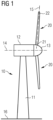
- FIG. 1 shows a conventional wind turbine 10 for generating electricity.
- the wind turbine 10 comprises a tower 11 which is mounted on the ground 16 by one end. At the opposite end of the tower 11 there is mounted a nacelle 12.
- the nacelle 12 is usually mounted rotatable with regard to the tower 11, which is referred to as comprising a yaw axis substantially perpendicular to the ground 16.
- the nacelle 12 usually accommodates the generator of the wind turbine and the gear box (if the wind turbine is a geared wind turbine).
- the wind turbine 10 comprises a hub 13 which is rotatable about a substantially horizontal rotor axis 14.
- the hub 13 is often described as being a part of the rotor, wherein the rotor is capable to transfer the rotational energy to the generator.
- the hub 13 is the part at which the rotor blades 20 are mounted.
- Each rotor blade 20 is usually mounted pivotable to the hub 13.
- the rotor blades 20 can be pitched about pitch axes 15, respectively. This improves the control of the wind turbine and in particular of the rotor blades by the possibility of modifying the direction at which the wind is hitting the rotor blades 20.
- Each rotor blade 20 is mounted to the hub 13 at its root section 21.
- the root section 21 is opposed to the tip section 22 of the rotor blade. Note that in the example as shown in Figure 1 , only two rotor blades 20 are depicted. However, most modern wind turbines comprise three rotor blades.
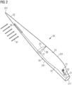
- FIG. 2 illustrates a rotor blade 20 comprising an aerodynamic device 30.
- the rotor blade 20 comprises a root section 21 with a root 211 and a tip section 22 with a tip 221.
- the rotor blade 20 furthermore comprises an airfoil section which is characterized in that it is able to generate lift and comprising a suction side 25 and a pressure side 26.
- the airfoil shape of the airfoil portion is symbolized by one airfoil profile which is shown in Figure 2 and which illustrates the cross-sectional shape of the rotor blade at this spanwise position.
- the suction side 25 is divided or separated from the pressure side 26 by a chord line 27 which connects the leading edge 241 with the trailing edge 231 of the rotor blade 20.
- the area around the trailing edge 231 is commonly referred to as the trailing edge section 23.
- the area around the leading edge 241 is commonly referred to as the leading edge section 24.
- a feature which distinguishes the rotor blade 20 as illustrated in Figure 2 from a standard prior art rotor blade is the provision of the aerodynamic device 30.
- the aerodynamic device 30 is arranged substantially along the length axis of the rotor blade, which is defined as the axis from the root 211 to the tip 221 of the rotor blade 20. In the example shown in Figure 2 , the aerodynamic device 30 extends over ca. fifteen percent of the length of the rotor blade.
- the aerodynamic device 30 in Figure 2 is movable by means of a pressure hose which will be shown and described in more detail in the following Figures.
- a pressure hose is one example of a pneumatic actuator.
- Another example of a pneumatic actuator is an (inflatable) cavity.
- Figure 2 furthermore discloses the pressure supply system of the aerodynamic device 30 comprising a control unit 51, a pressure supply system 52 and pressure lines 53.
- the pressure supply system 52 provides pressurized air.
- pressurized air not only comprises positive pressure but also negative pressure, wherein air is sucked (or "drawn") out of the pressure hose of the aerodynamic device 30.
- the pressure lines 53 could in practice be realized as tubes or pipes which do not significantly change their volume.
- the control unit 51 is responsible for setting a specific pressure at the pressure supply system 52 which subsequently leads to a certain predetermined pressure at the aerodynamic device 30.
- control unit 51 and the pressure supply system 52 are located in the root section 21 of the rotor blade 20.
- control unit 51 and the pressure supply system 52 are located in the root section 21 of the rotor blade 20.
- these parts could also be placed elsewhere in the wind turbine, such as e.g. in the hub of the wind turbine.
- FIG 3 shows a variant of the rotor blade shown in Figure 2 .
- the rotor blade as shown in Figure 3 additionally comprises a flow regulating unit 40 comprising multiple pairs of vortex generators.
- Such vortex generators arranged in pairs on wind turbine rotor blades are well-known both from literature and concrete industrial products.
- the flow regulating unit 40 is arranged downstream of the aerodynamic device 30. Therefore, the flow regulating unit can be “switched on” and “off” selectively by activating and deactivating the pneumatic actuator of the aerodynamic device 30.
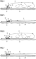
- Figures 4 and 5 illustrate a first embodiment of a fail-safe aerodynamic device 30 according to the invention.
- Figure 4 shows the situation that the aerodynamic device 30 is in its first configuration. This means that in the situation as illustrated in Figure 4 , no pressure is applied to the pressure hose 31 of the aerodynamic device 30. As a consequence, the fluid 62 inside the hose 31 is at a predetermined pressure which may e.g. approach or be equal to the atmospheric pressure.
- the aerodynamic device 30 comprises a first portion 34.
- the first portion 34 is relatively stiff and rigid. It is at least rigid enough to resist and deviate the airflow 61 which is flowing from the leading edge section to the trailing edge section of the rotor blade.
- the first portion 34 of the aerodynamic device 30 protrudes. In other words, the first portion 34 projects away from the surface 28 of the rotor blade.
- the aerodynamic device 30 further comprises a pneumatic actuator, which is realized as a hose 31 in the first embodiment of the aerodynamic device 30.
- the hose 31 comprises an elastic outer skin such that it can expand and collapse (or, in other words, inflate and deflate) reversibly and during many cycles.
- the aerodynamic device 30 further comprises a bending part 33.
- the bending part 33 is made of flexible material, such as e.g. rubber or a synthetic material.
- the bending part 33 functions as a hinge.
- the bending part 33 enables a change of orientation of the first portion 34 between an upright position (as in Figure 4 ) or a flat position (as in Figure 5 ).
- the aerodynamic device 30 does project upwards is due to the fact that the aerodynamic device 30 is provided with a pretension. In particular, it is the bending part 33, which is provided with a pretension.
- the aerodynamic device 30 in its first configuration - as illustrated in Figure 4 - induces stall. This is visualized with relatively large vortices 63 downstream of the aerodynamic device 30. A consequence of the induced stall is a decrease in lift of the rotor blade and, consequently, a reduced loading of the rotor blade and related components of the wind turbine.
- Figure 5 shows the same aerodynamic device 30 as in Figure 4 , but in the second instead of the first configuration.
- the second configuration is different from the first one in that a negative pressure is applied to the fluid 62 inside the hose 31.
- the first section 34 has moved downwards towards the surface 28 of the rotor blade.
- the airflow 61 flowing across the aerodynamic device 30 is influenced differently.
- the airflow 61 remains attached to the surface 28 of the rotor blade, thus that no flow separation, i.e. stall, occurs.
- the lift of the rotor blade increases.
- the fail-safe feature of aerodynamic device 30 consists in the fact that if connection between the control unit/ pressure supply system and the aerodynamic device 30 is disrupted, the aerodynamic device 30 automatically moves into the first configuration, cf. Figure 4 . As a consequence, the lift and load of the rotor blade is minimized, which is generally desired in the assumed case that connection between the control unit/ pressure supply system and the aerodynamic device 30 is disrupted.
- FIGS 6 and 7 show a second embodiment of an aerodynamic device 30.
- similar or identical elements, which have already been introduced for the first embodiment of the aerodynamic device 30 will not be repeated.
- Figure 6 shows the aerodynamic device 30 in its first configuration, i.e. in its "neutral" position without application of any pressure by the pressure supply system.
- the airflow 61 is spoiled, stall is induced, and, consequently, lift and load is reduced.
- the aerodynamic device 30 of the second embodiment is slightly differently designed compared to the aerodynamic device 30 of the first embodiment.
- both embodiments comprise a first portion 34, which protrude in the first configuration of the aerodynamic device 30 and which is buried (or embedded) in the second configuration
- the change of configuration in the second embodiment is not realized by applying a negative pressure, but by applying a positive pressure.
- the first portion 34 of the aerodynamic device 30 is brought downwards by drawing the fluid out of the pneumatic actuator, while in the second embodiment, this is achieved by pressing fluid into the pneumatic actuator.
- a pressure (a positive one or a negative one) needs to be actively applied on the pneumatic actuator for achieving a high lift of the rotor blade. If no pressure is applied, the pneumatic actuator makes the first portion 34 move into the "small-lift", "low-load” configuration.
- the pneumatic actuator is realized as a hose 31 in the first embodiment and as a cavity 32 in the second embodiment. This is, however, not relevant for the functionality of the fail-safe mechanism. The mechanism would also perfectly work if the aerodynamic device of the first embodiment was realized as a cavity and the aerodynamic device of the second embodiment was realized as a hose.
- FIGS 8 and 9 show a third embodiment of an aerodynamic device 30. Again, for sake of conciseness, similar or identical elements, which have already be introduced for the first or second embodiment of the aerodynamic device 30 will not be repeated here.
- Figure 8 shows the aerodynamic device 30 in its first configuration, i.e. in its "neutral" position without application of any pressure by the pressure supply system.
- the airflow 61 is spoiled, stall is induced, and, consequently, lift and load is reduced.
- Figure 9 shows the aerodynamic device 30 in its second configuration.
- the first portion 34 of the aerodynamic device 30 is flat such that the airflow 61 flowing across the aerodynamic device 30 is not stalled.
- the similarity between the second and the third embodiment consists in that for both embodiments, a positive pressure needs to be applied to the pneumatic actuator of the aerodynamic device 30 in order to change the aerodynamic device 30 from its first into its second configuration.
- the modification of the third embodiment with regard to the second embodiment is that in the third embodiment the aerodynamic device 30 is predominantly embedded into the shell 29 of the rotor blade. This has the advantage that drag of the aerodynamic device 30 is minimized. This is especially advantageous in the second configuration of aerodynamic device 30, when an increase as high as possible of the lift of the rotor blade is generally desired.
- the third embodiment of the aerodynamic device 30 proposes an attractive solution to this desire, as the aerodynamic device 30 is almost flush with the surface 28 of the rotor blade in its second configuration.
- Figures 10 and 11 show a variant of the second embodiment of an aerodynamic device 30 according to the invention.
- the sole difference between the aerodynamic device 30 as shown and described in Figures 6 and 7 is that the embodiment of the aerodynamic device 30 shown in Figures 10 and 11 additionally comprises a flow regulating unit 40 at its first portion 34.
- the flow regulating unit may be shaped as a pair of vortex generators.
- the flow regulating unit 40 does not have a significant influence on the airflow 61 in the first configuration of the aerodynamic device 30.
- the airflow 61 is spoiled, i.e. stalled, anyway and the flow regulating unit 40 does not change this.
- the airflow 61 is not only not spoiled by the aerodynamic device 30, but the boundary layer is even reenergized by re-energizing vortices 64, which are typically induced by vortex generators under suitable flow conditions.
- the effect is that the lift of the rotor blade is even further increased.
- the equipment of the aerodynamic device 30 by a flow regulating unit 40 is in principle capable to even further increase the lift of the rotor blade in the second configuration of the aerodynamic device 30.
- Figures 12 and 13 shows a combination of the first embodiment of the aerodynamic device 30 as shown in Figures 4 and 5 with a flow regulating unit 40, such as a vortex generator.
- a vortex generator is in principle able to increase the lift of a rotor blade due to re-energizing vortices 64 which it may induce in the boundary layer.
- a fail-safe aerodynamic device 30 with a flow regulating unit 40 results in a particularly powerful tool for, on the one hand, maximizing the lift of a rotor blade without, on the other hand, compromising safety issues in case of a failure of the system.
- FIG 13 is the situation where a lift of the rotor blade as high as possible is aimed for.
- the aerodynamic device 30 is made as flat as possible (by e.g. drawing air out of the pressure hose of the aerodynamic device 30) for not spoiling the airflow 61 flowing across it, and, at the same time, the flow regulating unit 40 ensures an additional increase in the lift due to the generation of re-energizing vortices 64.
- a lift of the rotor blade as high as possible is achieved.
- the aerodynamic device 30 automatically moves into the first configuration, which is depicted in Figure 12 .
- the aim is to minimize the lift of the rotor blade as much as possible because this involves a reduction of the load of the rotor blade and related components of the wind turbine as much as possible.
- a fail-safe aerodynamic device 30 with a flow regulating unit 40 placed downstream of the aerodynamic device 30 represents a particularly useful and advantageous option for optimizing the aerodynamic properties of a rotor blade in a fail-safe manner.
- Figures 14 and 15 show a different embodiment of combining an aerodynamic device 30 with a flow regulating unit 40.
- the flow regulating unit 40 is placed "before", i.e. upstream of the aerodynamic device 30. This does not allow the aerodynamic device 30 to directly activate or deactivate the flow regulating unit 40, but may, nevertheless, also represent an attractive option to achieve a high lift of a rotor blade without compromising safety issues in case of a failure of the system.
- Figure 15 represents the situation wherein the aerodynamic device 30 is in its second configuration, i.e. a lift of the rotor blade as high as possible is aimed for. This is effectively achieved by the arrangement as disclosed in Figure 15 , because the flow regulating unit 40 generates re-energizing vortices 64 which pass by the aerodynamic device 30 substantially undisturbed as the aerodynamic device 30 is "flat".
- This "flat" configuration of the aerodynamic device 30 may, in the exemplary design of the aerodynamic device 30 as shown in Figures 14 and 15 , be achieved by applying a negative pressure to the pressure hose of the aerodynamic device 30.
- the first portion 34 of the aerodynamic device 30 changes its orientation and moves from the "flat" position into an upright position, cf. Figure 14 .
- This does, however, not directly impact the generation of re-energizing vortices 64 by the flow regulating unit 40, as the flow regulating unit 40 is located upstream of the aerodynamic device 30.
- these re-energizing vortices 64 shortly after being generated approach the aerodynamic device 30, in particular the protruding first section 34 thereof, these re-energizing vortices 64 are deviated the same as the remaining airflow 61 and are destroyed.
- the airflow 61 is separated from the suction side 25 of the rotor blade approximately at the location where the aerodynamic device 30 is situated.
- the small lift-enhancing effect of the re-energizing vortices 64 is heavily outweighed by the flow separation induced by the aerodynamic device 30 which is in its first configuration and the overall lift (and load) of the rotor blade is significantly reduced.
- Figure 16 visualizes the difference between the first and second configuration of the aerodynamic device 30 in terms of its impact on the lift curve.
- the lift 71 of the rotor blade is shown depending on the angle of attack 72.
- the first curve 73 represents the lift of the rotor blade when the aerodynamic device is in its first configuration.
- the lift 71 increases with increasing angles of attack 72 (at least for angles of attack 72 greater than zero) until a maximum value for the lift is reached.
- This maximum lift for the first curve 73 is referenced to by the reference sign 731.
- the second curve 74 represents the lift of the rotor blade when the aerodynamic device is in its second configuration. Again, the lift 71 increases with increasing angles of attack 72 until a maximum value for the lift is reached. This maximum lift for the second curve 74 is referenced to by the reference sign 741.
- the lift of the rotor blade is higher when the aerodynamic device is in its second configuration compared to the first configuration. This is - at least in the example shown here - valid for all relevant angles of attack greater than zero, and in particular also for the respective maximum lift values 731, 741.
Landscapes
- Engineering & Computer Science (AREA)
- Life Sciences & Earth Sciences (AREA)
- Sustainable Development (AREA)
- Sustainable Energy (AREA)
- Chemical & Material Sciences (AREA)
- Combustion & Propulsion (AREA)
- Mechanical Engineering (AREA)
- General Engineering & Computer Science (AREA)
- Physics & Mathematics (AREA)
- Fluid Mechanics (AREA)
- Wind Motors (AREA)
Claims (15)
- Pale de rotor (20) pour une éolienne (10), la pale de rotor (20) comprenant- un dispositif aérodynamique (30) pour influencer le flux d'air (61) s'écoulant de la section de bord d'attaque (24) de la pale de rotor (20) à la section de bord de fuite (23) de la pale de rotor (20), dans laquelle le dispositif aérodynamique (30) est monté sur une surface (28) de la pale de rotor (20) et comprend un actionneur pneumatique ou hydraulique, tel qu'un tuyau (31) ou une cavité (32), dont le volume dépend de la pression d'un fluide (62) présent à l'intérieur de l'actionneur pneumatique ou hydraulique ;- une unité de régulation de débit (40) pour influencer le flux d'air (61) s'écoulant de la section de bord d'attaque (24) de la pale de rotor (20) à la section de bord de fuite (23) de la pale de rotor (20), et- une unité de contrôle (51) pour contrôler la pression du fluide (62) dans l'actionneur pneumatique ou hydraulique du dispositif aérodynamique (30),dans laquelle le dispositif aérodynamique (30) comprend une première section (34) et une partie pliée (33),dans laquelle la partie pliée (33) fonctionne comme une charnière, de sorte que lorsqu'aucune pression au fluide (62) dans l'actionneur pneumatique ou hydraulique n'est induite par l'unité de commande (51), la première section (34) est dans une première position en saillie à l'écart de la surface (28) de la pale de rotor (20), entraînant le dispositif aérodynamique (30) dans une première configuration, etlorsque l'unité de commande (51) induit l'application d'une pression positive ou négative sur le fluide (62) dans l'actionneur pneumatique ou hydraulique, l'actionneur pneumatique ou hydraulique est dilaté ou replié pour faire tourner la première section (34) vers une deuxième position se rapprochant de la surface (28) de la pale de rotor (20), amenant le dispositif aérodynamique (30) dans une deuxième configuration, telle que- la portance (71) de la pale de rotor (20) dans la première configuration est inférieure à la portance (71) de la pale de rotor (20) dans la deuxième configuration.
- Pale de rotor (20) selon la revendication 1, dans laquelle la partie pliée (33) est en matériau souple qui permet le changement de configuration du dispositif aérodynamique (30) de la première configuration à la deuxième configuration et vice versa.
- Pale de rotor (20) selon la revendication 2, dans laquelle la saillie de la première section (34) loin de la surface (28) de la pale de rotor (20) est provoquée, ou au moins soutenue, en préréglant la partie pliée (33) du dispositif aérodynamique (30) .
- Pale de rotor (20) selon l'une des revendications 1 à 3, dans laquelle, dans la deuxième configuration du dispositif aérodynamique (30), le dispositif aérodynamique (30) est majoritairement ou même totalement encastré dans la coque (29) de la pale de rotor (20).
- Pale de rotor (20) selon l'une des revendications 1 à 3, dans laquelle le dispositif aérodynamique (30) s'étend sensiblement parallèlement à l'axe longitudinal de la pale de rotor (20).
- Pale de rotor (20) selon l'une des revendications 1 à 3, dans laquelle le dispositif aérodynamique (30) s'étend sur au moins dix pour cent, en particulier sur au moins quinze pour cent, de la longueur de la pale de rotor (20).
- Pale de rotor (20) selon l'une des revendications 1 à 3, dans laquelle le dispositif aérodynamique est placé entre le bord d'attaque (241) de la pale de rotor (20) et cinquante pour cent, de la longueur de corde de la pale de rotor (20), mesurée à partir du bord d'attaque (241).
- Pale de rotor (20) selon l'une des revendications 1 à 3, dans laquelle l'unité de régulation de débit (40) est un générateur de tourbillons.
- Pale de rotor (20) selon l'une des revendications 1 à 3, dans laquelle à la fois le dispositif aérodynamique (30) et l'unité de régulation de débit (40) sont montés sur le côté aspiration (25) de la pale de rotor (20).
- Pale de rotor (20) selon l'une des revendications 1 à 3, dans laquelle l'unité de régulation de débit (40) est placée entre le dispositif aérodynamique (30) et le bord de fuite (231) de la pale de rotor (20).
- Pale de rotor (20) selon la revendication 10, dans laquelle la distance dans le sens de la corde entre le dispositif aérodynamique (30) et l'unité de régulation de débit (40) est comprise entre dix pour cent et cinquante pour cent de la longueur de corde de la pale de rotor (20).
- Pale de rotor (20) selon l'une des revendications 1 à 3, dans laquelle le dispositif de régulation de débit (40) est placé entre le bord d'attaque (241) de la pale de rotor et le dispositif aérodynamique (30).
- Pale de rotor (20) selon la revendication 12, dans laquelle la distance dans le sens de la corde entre le dispositif aérodynamique (30) et l'unité de régulation de débit (40) est comprise entre un pour cent et vingt pour cent de la longueur de corde de la pale de rotor (20).
- Pale de rotor (20) selon l'une des revendications 1 à 3, dans laquelle le dispositif aérodynamique (30) lui-même est équipé de l'unité de régulation de débit (40).
- Éolienne (10) pour produire de l'électricité comprenant au moins une pale de rotor (20) selon l'une des revendications 1 à 14.
Applications Claiming Priority (2)
| Application Number | Priority Date | Filing Date | Title |
|---|---|---|---|
| EP16186403.8A EP3290688B1 (fr) | 2016-08-30 | 2016-08-30 | Contrôle de la vitesse de rotation par modification du profil de pale |
| PCT/EP2017/058492 WO2018041420A1 (fr) | 2016-08-30 | 2017-04-10 | Agencement de régulation de débit pour pale de rotor d'éolienne |
Publications (2)
| Publication Number | Publication Date |
|---|---|
| EP3488101A1 EP3488101A1 (fr) | 2019-05-29 |
| EP3488101B1 true EP3488101B1 (fr) | 2023-03-15 |
Family
ID=70737697
Family Applications (1)
| Application Number | Title | Priority Date | Filing Date |
|---|---|---|---|
| EP17717135.2A Active EP3488101B1 (fr) | 2016-08-30 | 2017-04-10 | Agencement de régulation de débit pour pale de rotor d'éolienne |
Country Status (5)
| Country | Link |
|---|---|
| US (1) | US11078885B2 (fr) |
| EP (1) | EP3488101B1 (fr) |
| CN (1) | CN109996956B (fr) |
| DK (1) | DK3488101T3 (fr) |
| WO (1) | WO2018041420A1 (fr) |
Families Citing this family (29)
| Publication number | Priority date | Publication date | Assignee | Title |
|---|---|---|---|---|
| CN109996956B (zh) | 2016-08-30 | 2021-12-28 | 西门子歌美飒可再生能源公司 | 用于风力涡轮机转子叶片的流控制装置 |
| DK3577339T3 (da) * | 2017-03-07 | 2022-08-08 | Siemens Gamesa Renewable Energy As | Trykforsyningssystem til en pneumatisk aktiverbar aerodynamisk indretning af en rotorvinge af en vindmølle |
| EP3667061A1 (fr) | 2018-12-13 | 2020-06-17 | Siemens Gamesa Renewable Energy A/S | Déflecteur adaptable pour une pale de rotor de turbine éolienne |
| EP3667068A1 (fr) | 2018-12-13 | 2020-06-17 | Siemens Gamesa Renewable Energy A/S | Déflecteur adaptable pour une pale d'éolienne |
| EP3667067A1 (fr) * | 2018-12-13 | 2020-06-17 | Siemens Gamesa Renewable Energy A/S | Détection de défaut d'ajustement de pale de rotor d'éolienne |
| EP3667081A1 (fr) | 2018-12-13 | 2020-06-17 | Siemens Gamesa Renewable Energy A/S | Régulation de flux de pale d'éolienne |
| EP3667063A1 (fr) | 2018-12-13 | 2020-06-17 | Siemens Gamesa Renewable Energy A/S | Dispositif de drainage d'humidité dans des éoliennes |
| EP3667070A1 (fr) | 2018-12-13 | 2020-06-17 | Siemens Gamesa Renewable Energy A/S | État sécurisé d'une pale de turbine éolienne adaptable |
| EP3667072A1 (fr) * | 2018-12-13 | 2020-06-17 | Siemens Gamesa Renewable Energy A/S | Déflecteur adaptable pour une pale d'éolienne |
| EP3667064A1 (fr) | 2018-12-13 | 2020-06-17 | Siemens Gamesa Renewable Energy A/S | Amortissement de vibrations dans une éolienne |
| EP3667074A1 (fr) | 2018-12-13 | 2020-06-17 | Siemens Gamesa Renewable Energy A/S | Dispositif et procédé d'amortissement des mouvements avant et arrière d'une tour d'éolienne |
| EP3667073A1 (fr) * | 2018-12-13 | 2020-06-17 | Siemens Gamesa Renewable Energy A/S | Commande d'éléments d'appoint complémentaires d'une pale d'éolienne |
| EP3667082A1 (fr) | 2018-12-13 | 2020-06-17 | Siemens Gamesa Renewable Energy A/S | Régulation de flux de pale d'éolienne |
| EP3667077A1 (fr) | 2018-12-13 | 2020-06-17 | Siemens Gamesa Renewable Energy A/S | Adaptation rapide de régulation de flux de pale d'éolienne |
| EP3667062A1 (fr) | 2018-12-13 | 2020-06-17 | Siemens Gamesa Renewable Energy A/S | Dispositif de contrôle de l'humidité dans des éoliennes |
| EP3667080A1 (fr) | 2018-12-13 | 2020-06-17 | Siemens Gamesa Renewable Energy A/S | Régulation de flux de pale d'éolienne |
| EP3730779A1 (fr) | 2019-04-25 | 2020-10-28 | Siemens Gamesa Renewable Energy A/S | Système de tuyauterie de transmission de fluide pour pale de rotor d'éolienne |
| US11614083B2 (en) | 2019-09-10 | 2023-03-28 | GM Global Technology Operations LLC | Internally tensioned inflatable structure that is posable in multiple positions |
| US11084541B2 (en) * | 2019-09-10 | 2021-08-10 | GM Global Technology Operations LLC | Internally tensioned inflatable structures |
| DE202019106227U1 (de) * | 2019-11-08 | 2021-02-10 | Rehau Ag + Co | Aktivierungsanordnung für bewegbare Klappvorrichtungen |
| EP3832127A1 (fr) | 2019-12-05 | 2021-06-09 | Siemens Gamesa Renewable Energy A/S | Régulation de flux de pale d'éolienne |
| EP3885572A1 (fr) * | 2020-03-25 | 2021-09-29 | Siemens Gamesa Renewable Energy A/S | Réduction de charge aérodynamique pendant l'installation et le fonctionnement de pales dans une éolienne |
| EP3907401A1 (fr) | 2020-05-05 | 2021-11-10 | Siemens Gamesa Renewable Energy A/S | Dispositif de modification de levage d'une pale de rotor, pale de rotor d'une éolienne et procédé pour modifier le levage d'une pale de rotor |
| EP3913212A1 (fr) * | 2020-05-19 | 2021-11-24 | Siemens Gamesa Renewable Energy A/S | Pale d'éolienne comprenant des moyens pour retenir un déflecteur dans une position rétractée |
| EP3919737A1 (fr) * | 2020-06-05 | 2021-12-08 | Siemens Gamesa Renewable Energy A/S | Dispositif et procédé de commande du fonctionnement d'une éolienne pour réduire la charge au désalignement du lacet |
| EP4039965A1 (fr) * | 2021-02-05 | 2022-08-10 | Siemens Gamesa Renewable Energy A/S | Élément aérodynamique d'une pale d'une éolienne |
| EP4050205A1 (fr) | 2021-02-25 | 2022-08-31 | Siemens Gamesa Renewable Energy A/S | Pale de rotor dotée d'un dispositif aérodynamique réglable pour une éolienne |
| EP4050204A1 (fr) | 2021-02-25 | 2022-08-31 | Siemens Gamesa Renewable Energy A/S | Pale de rotor dotée d'un dispositif aérodynamique réglable comprenant un actionneur à base de polymère électroactif diélectrique pour une éolienne |
| EP4194683B1 (fr) * | 2021-12-09 | 2026-05-06 | Ge Vernova Renovables España, S.L. | Pales d'éolienne, ensembles pale d'éolienne et procédés associés |
Family Cites Families (21)
| Publication number | Priority date | Publication date | Assignee | Title |
|---|---|---|---|---|
| US3136501A (en) | 1961-10-23 | 1964-06-09 | Ernest H Barber | Aircraft wing construction |
| DE3913505A1 (de) | 1989-04-25 | 1989-11-16 | Astrid Holzem | Fluegel mit aerodynamischer bremse fuer windkraftmaschinen |
| US5326050A (en) | 1993-02-08 | 1994-07-05 | The United States Of America As Represented By The Administrator Of National Aeronautics And Space Administration | Aerodynamic surface distension system for high angle of attack forebody vortex control |
| DK174261B1 (da) | 2000-09-29 | 2002-10-21 | Bonus Energy As | Anordning til brug ved regulering af luftstrømning omkring en vindmøllevinge |
| US6837465B2 (en) * | 2003-01-03 | 2005-01-04 | Orbital Research Inc | Flow control device and method of controlling flow |
| DK200300670A (da) | 2003-05-05 | 2004-11-06 | Lm Glasfiber As | Vindmölleving med opdriftsregulerende organer |
| US9039372B2 (en) | 2007-04-30 | 2015-05-26 | Vestas Wind Systems A/S | Wind turbine blade |
| EP1995455B1 (fr) | 2007-05-25 | 2016-11-16 | Siemens Aktiengesellschaft | Système d'actionnement d'un volet de pale d'éolienne |
| WO2009080316A2 (fr) | 2007-12-21 | 2009-07-02 | Vestas Wind Systems A/S | Dispositif de contrôle de flux actif et procédé pour affecter une couche limite de fluide d'une pale d'éolienne |
| US8267654B2 (en) | 2008-05-16 | 2012-09-18 | Frontier Wind, Llc | Wind turbine with gust compensating air deflector |
| CN102165185B (zh) | 2008-08-29 | 2013-07-24 | 维斯塔斯风力系统有限公司 | 风轮机叶片中的控制系统 |
| US20110142595A1 (en) * | 2010-07-02 | 2011-06-16 | General Electric Company | Wind turbine blades with controlled active flow and vortex elements |
| JP5479388B2 (ja) * | 2011-02-28 | 2014-04-23 | 三菱重工業株式会社 | 風車翼およびこれを備えた風力発電装置 |
| US8491262B2 (en) * | 2011-10-27 | 2013-07-23 | General Electric Company | Method for shut down of a wind turbine having rotor blades with fail-safe air brakes |
| ES2388514B1 (es) | 2012-05-18 | 2013-07-09 | Manuel Torres Martínez | Pala de aerogenerador, de geometría variable con control pasivo |
| US20150010407A1 (en) * | 2013-07-08 | 2015-01-08 | Alonso O. Zamora Rodriguez | Reduced noise vortex generator for wind turbine blade |
| US9689374B2 (en) | 2013-10-09 | 2017-06-27 | Siemens Aktiengesellschaft | Method and apparatus for reduction of fatigue and gust loads on wind turbine blades |
| US9926911B2 (en) * | 2014-09-12 | 2018-03-27 | Ge Infrastructure Technology, Llc | Wind turbine air deflector system control |
| DE202015000665U1 (de) * | 2015-01-24 | 2015-06-26 | Dieter Röhm | Vorrichtung eines Sicherheitssystems und/oder Ressourcen-/Energieeffizienz-Verbesserungs - Systems zur Stömungsbeeinflussung eines Aero- oder Hydrodynamischen Körpers (3), nach dem Prinzip einer Rückstromklappe (4) |
| CN109996956B (zh) | 2016-08-30 | 2021-12-28 | 西门子歌美飒可再生能源公司 | 用于风力涡轮机转子叶片的流控制装置 |
| DK3290688T3 (da) | 2016-08-30 | 2021-02-01 | Siemens Gamesa Renewable Energy As | Regulering af rotationshastighed ved ændring af vingeprofil |
-
2017
- 2017-04-10 CN CN201780066806.2A patent/CN109996956B/zh active Active
- 2017-04-10 US US16/327,347 patent/US11078885B2/en active Active
- 2017-04-10 WO PCT/EP2017/058492 patent/WO2018041420A1/fr not_active Ceased
- 2017-04-10 EP EP17717135.2A patent/EP3488101B1/fr active Active
- 2017-04-10 DK DK17717135.2T patent/DK3488101T3/da active
Also Published As
| Publication number | Publication date |
|---|---|
| CN109996956B (zh) | 2021-12-28 |
| EP3488101A1 (fr) | 2019-05-29 |
| CN109996956A (zh) | 2019-07-09 |
| US20190186463A1 (en) | 2019-06-20 |
| WO2018041420A1 (fr) | 2018-03-08 |
| US11078885B2 (en) | 2021-08-03 |
| DK3488101T3 (da) | 2023-05-01 |
Similar Documents
| Publication | Publication Date | Title |
|---|---|---|
| US11078885B2 (en) | Flow control arrangement for a wind turbine rotor blade | |
| US8827644B2 (en) | Wind turbine rotor blade | |
| CA2634427C (fr) | Systeme d'actionnement pour volet de pale d'eolienne | |
| EP3577339B1 (fr) | Système d'alimentation en pression pour un dispositif aérodynamique à activation pneumatique d'une pale de rotor d'une éolienne | |
| EP3577338B1 (fr) | Système de sécurité pour dispositif aérodynamique d'une pale de rotor d'éolienne | |
| US10677217B2 (en) | Wind turbine and method of operating the same | |
| EP3267031B1 (fr) | Aube de rotor d'éolienne avec générateurs de vortex | |
| EP4121651B1 (fr) | Pale de rotor d'éolienne comprenant un dispositif de modification de portance et procédé d'installation associé | |
| EP2141357A1 (fr) | Pale d'éolienne | |
| CN113167232B (zh) | 抑制风力涡轮机中的振动 | |
| EP3894698B1 (fr) | Régulation de flux de pale d'éolienne | |
| EP3667065A1 (fr) | Élimination de vibrations dans des pales d'éolienne | |
| EP3867521B1 (fr) | Éolienne | |
| US12577935B2 (en) | Rotor blade active flap |
Legal Events
| Date | Code | Title | Description |
|---|---|---|---|
| STAA | Information on the status of an ep patent application or granted ep patent |
Free format text: STATUS: UNKNOWN |
|
| STAA | Information on the status of an ep patent application or granted ep patent |
Free format text: STATUS: THE INTERNATIONAL PUBLICATION HAS BEEN MADE |
|
| PUAI | Public reference made under article 153(3) epc to a published international application that has entered the european phase |
Free format text: ORIGINAL CODE: 0009012 |
|
| STAA | Information on the status of an ep patent application or granted ep patent |
Free format text: STATUS: REQUEST FOR EXAMINATION WAS MADE |
|
| 17P | Request for examination filed |
Effective date: 20190225 |
|
| AK | Designated contracting states |
Kind code of ref document: A1 Designated state(s): AL AT BE BG CH CY CZ DE DK EE ES FI FR GB GR HR HU IE IS IT LI LT LU LV MC MK MT NL NO PL PT RO RS SE SI SK SM TR |
|
| AX | Request for extension of the european patent |
Extension state: BA ME |
|
| DAV | Request for validation of the european patent (deleted) | ||
| DAX | Request for extension of the european patent (deleted) | ||
| STAA | Information on the status of an ep patent application or granted ep patent |
Free format text: STATUS: EXAMINATION IS IN PROGRESS |
|
| STAA | Information on the status of an ep patent application or granted ep patent |
Free format text: STATUS: REQUEST FOR EXAMINATION WAS MADE |
|
| STAA | Information on the status of an ep patent application or granted ep patent |
Free format text: STATUS: EXAMINATION IS IN PROGRESS |
|
| 17Q | First examination report despatched |
Effective date: 20211011 |
|
| 17Q | First examination report despatched |
Effective date: 20211022 |
|
| GRAP | Despatch of communication of intention to grant a patent |
Free format text: ORIGINAL CODE: EPIDOSNIGR1 |
|
| STAA | Information on the status of an ep patent application or granted ep patent |
Free format text: STATUS: GRANT OF PATENT IS INTENDED |
|
| INTG | Intention to grant announced |
Effective date: 20221018 |
|
| GRAS | Grant fee paid |
Free format text: ORIGINAL CODE: EPIDOSNIGR3 |
|
| GRAA | (expected) grant |
Free format text: ORIGINAL CODE: 0009210 |
|
| STAA | Information on the status of an ep patent application or granted ep patent |
Free format text: STATUS: THE PATENT HAS BEEN GRANTED |
|
| AK | Designated contracting states |
Kind code of ref document: B1 Designated state(s): AL AT BE BG CH CY CZ DE DK EE ES FI FR GB GR HR HU IE IS IT LI LT LU LV MC MK MT NL NO PL PT RO RS SE SI SK SM TR |
|
| REG | Reference to a national code |
Ref country code: CH Ref legal event code: EP Ref country code: GB Ref legal event code: FG4D |
|
| REG | Reference to a national code |
Ref country code: DE Ref legal event code: R096 Ref document number: 602017066804 Country of ref document: DE |
|
| REG | Reference to a national code |
Ref country code: IE Ref legal event code: FG4D |
|
| REG | Reference to a national code |
Ref country code: AT Ref legal event code: REF Ref document number: 1554138 Country of ref document: AT Kind code of ref document: T Effective date: 20230415 |
|
| REG | Reference to a national code |
Ref country code: DK Ref legal event code: T3 Effective date: 20230426 |
|
| REG | Reference to a national code |
Ref country code: LT Ref legal event code: MG9D |
|
| REG | Reference to a national code |
Ref country code: NL Ref legal event code: MP Effective date: 20230315 |
|
| PG25 | Lapsed in a contracting state [announced via postgrant information from national office to epo] |
Ref country code: RS Free format text: LAPSE BECAUSE OF FAILURE TO SUBMIT A TRANSLATION OF THE DESCRIPTION OR TO PAY THE FEE WITHIN THE PRESCRIBED TIME-LIMIT Effective date: 20230315 Ref country code: NO Free format text: LAPSE BECAUSE OF FAILURE TO SUBMIT A TRANSLATION OF THE DESCRIPTION OR TO PAY THE FEE WITHIN THE PRESCRIBED TIME-LIMIT Effective date: 20230615 Ref country code: LV Free format text: LAPSE BECAUSE OF FAILURE TO SUBMIT A TRANSLATION OF THE DESCRIPTION OR TO PAY THE FEE WITHIN THE PRESCRIBED TIME-LIMIT Effective date: 20230315 Ref country code: LT Free format text: LAPSE BECAUSE OF FAILURE TO SUBMIT A TRANSLATION OF THE DESCRIPTION OR TO PAY THE FEE WITHIN THE PRESCRIBED TIME-LIMIT Effective date: 20230315 Ref country code: HR Free format text: LAPSE BECAUSE OF FAILURE TO SUBMIT A TRANSLATION OF THE DESCRIPTION OR TO PAY THE FEE WITHIN THE PRESCRIBED TIME-LIMIT Effective date: 20230315 |
|
| REG | Reference to a national code |
Ref country code: AT Ref legal event code: MK05 Ref document number: 1554138 Country of ref document: AT Kind code of ref document: T Effective date: 20230315 |
|
| PG25 | Lapsed in a contracting state [announced via postgrant information from national office to epo] |
Ref country code: SE Free format text: LAPSE BECAUSE OF FAILURE TO SUBMIT A TRANSLATION OF THE DESCRIPTION OR TO PAY THE FEE WITHIN THE PRESCRIBED TIME-LIMIT Effective date: 20230315 Ref country code: NL Free format text: LAPSE BECAUSE OF FAILURE TO SUBMIT A TRANSLATION OF THE DESCRIPTION OR TO PAY THE FEE WITHIN THE PRESCRIBED TIME-LIMIT Effective date: 20230315 Ref country code: GR Free format text: LAPSE BECAUSE OF FAILURE TO SUBMIT A TRANSLATION OF THE DESCRIPTION OR TO PAY THE FEE WITHIN THE PRESCRIBED TIME-LIMIT Effective date: 20230616 Ref country code: FI Free format text: LAPSE BECAUSE OF FAILURE TO SUBMIT A TRANSLATION OF THE DESCRIPTION OR TO PAY THE FEE WITHIN THE PRESCRIBED TIME-LIMIT Effective date: 20230315 |
|
| PG25 | Lapsed in a contracting state [announced via postgrant information from national office to epo] |
Ref country code: SM Free format text: LAPSE BECAUSE OF FAILURE TO SUBMIT A TRANSLATION OF THE DESCRIPTION OR TO PAY THE FEE WITHIN THE PRESCRIBED TIME-LIMIT Effective date: 20230315 Ref country code: RO Free format text: LAPSE BECAUSE OF FAILURE TO SUBMIT A TRANSLATION OF THE DESCRIPTION OR TO PAY THE FEE WITHIN THE PRESCRIBED TIME-LIMIT Effective date: 20230315 Ref country code: PT Free format text: LAPSE BECAUSE OF FAILURE TO SUBMIT A TRANSLATION OF THE DESCRIPTION OR TO PAY THE FEE WITHIN THE PRESCRIBED TIME-LIMIT Effective date: 20230717 Ref country code: ES Free format text: LAPSE BECAUSE OF FAILURE TO SUBMIT A TRANSLATION OF THE DESCRIPTION OR TO PAY THE FEE WITHIN THE PRESCRIBED TIME-LIMIT Effective date: 20230315 Ref country code: EE Free format text: LAPSE BECAUSE OF FAILURE TO SUBMIT A TRANSLATION OF THE DESCRIPTION OR TO PAY THE FEE WITHIN THE PRESCRIBED TIME-LIMIT Effective date: 20230315 Ref country code: CZ Free format text: LAPSE BECAUSE OF FAILURE TO SUBMIT A TRANSLATION OF THE DESCRIPTION OR TO PAY THE FEE WITHIN THE PRESCRIBED TIME-LIMIT Effective date: 20230315 Ref country code: AT Free format text: LAPSE BECAUSE OF FAILURE TO SUBMIT A TRANSLATION OF THE DESCRIPTION OR TO PAY THE FEE WITHIN THE PRESCRIBED TIME-LIMIT Effective date: 20230315 |
|
| PG25 | Lapsed in a contracting state [announced via postgrant information from national office to epo] |
Ref country code: SK Free format text: LAPSE BECAUSE OF FAILURE TO SUBMIT A TRANSLATION OF THE DESCRIPTION OR TO PAY THE FEE WITHIN THE PRESCRIBED TIME-LIMIT Effective date: 20230315 Ref country code: PL Free format text: LAPSE BECAUSE OF FAILURE TO SUBMIT A TRANSLATION OF THE DESCRIPTION OR TO PAY THE FEE WITHIN THE PRESCRIBED TIME-LIMIT Effective date: 20230315 Ref country code: IS Free format text: LAPSE BECAUSE OF FAILURE TO SUBMIT A TRANSLATION OF THE DESCRIPTION OR TO PAY THE FEE WITHIN THE PRESCRIBED TIME-LIMIT Effective date: 20230715 |
|
| REG | Reference to a national code |
Ref country code: CH Ref legal event code: PL |
|
| REG | Reference to a national code |
Ref country code: DE Ref legal event code: R097 Ref document number: 602017066804 Country of ref document: DE |
|
| PG25 | Lapsed in a contracting state [announced via postgrant information from national office to epo] |
Ref country code: LU Free format text: LAPSE BECAUSE OF NON-PAYMENT OF DUE FEES Effective date: 20230410 |
|
| REG | Reference to a national code |
Ref country code: BE Ref legal event code: MM Effective date: 20230430 |
|
| PG25 | Lapsed in a contracting state [announced via postgrant information from national office to epo] |
Ref country code: MC Free format text: LAPSE BECAUSE OF FAILURE TO SUBMIT A TRANSLATION OF THE DESCRIPTION OR TO PAY THE FEE WITHIN THE PRESCRIBED TIME-LIMIT Effective date: 20230315 |
|
| PLBE | No opposition filed within time limit |
Free format text: ORIGINAL CODE: 0009261 |
|
| STAA | Information on the status of an ep patent application or granted ep patent |
Free format text: STATUS: NO OPPOSITION FILED WITHIN TIME LIMIT |
|
| PG25 | Lapsed in a contracting state [announced via postgrant information from national office to epo] |
Ref country code: SI Free format text: LAPSE BECAUSE OF FAILURE TO SUBMIT A TRANSLATION OF THE DESCRIPTION OR TO PAY THE FEE WITHIN THE PRESCRIBED TIME-LIMIT Effective date: 20230315 Ref country code: MC Free format text: LAPSE BECAUSE OF FAILURE TO SUBMIT A TRANSLATION OF THE DESCRIPTION OR TO PAY THE FEE WITHIN THE PRESCRIBED TIME-LIMIT Effective date: 20230315 Ref country code: LI Free format text: LAPSE BECAUSE OF NON-PAYMENT OF DUE FEES Effective date: 20230430 Ref country code: CH Free format text: LAPSE BECAUSE OF NON-PAYMENT OF DUE FEES Effective date: 20230430 |
|
| REG | Reference to a national code |
Ref country code: IE Ref legal event code: MM4A |
|
| 26N | No opposition filed |
Effective date: 20231218 |
|
| PG25 | Lapsed in a contracting state [announced via postgrant information from national office to epo] |
Ref country code: BE Free format text: LAPSE BECAUSE OF NON-PAYMENT OF DUE FEES Effective date: 20230430 |
|
| PG25 | Lapsed in a contracting state [announced via postgrant information from national office to epo] |
Ref country code: IE Free format text: LAPSE BECAUSE OF NON-PAYMENT OF DUE FEES Effective date: 20230410 |
|
| PG25 | Lapsed in a contracting state [announced via postgrant information from national office to epo] |
Ref country code: IE Free format text: LAPSE BECAUSE OF NON-PAYMENT OF DUE FEES Effective date: 20230410 |
|
| PG25 | Lapsed in a contracting state [announced via postgrant information from national office to epo] |
Ref country code: IT Free format text: LAPSE BECAUSE OF FAILURE TO SUBMIT A TRANSLATION OF THE DESCRIPTION OR TO PAY THE FEE WITHIN THE PRESCRIBED TIME-LIMIT Effective date: 20230315 |
|
| PG25 | Lapsed in a contracting state [announced via postgrant information from national office to epo] |
Ref country code: BG Free format text: LAPSE BECAUSE OF FAILURE TO SUBMIT A TRANSLATION OF THE DESCRIPTION OR TO PAY THE FEE WITHIN THE PRESCRIBED TIME-LIMIT Effective date: 20230315 |
|
| PG25 | Lapsed in a contracting state [announced via postgrant information from national office to epo] |
Ref country code: BG Free format text: LAPSE BECAUSE OF FAILURE TO SUBMIT A TRANSLATION OF THE DESCRIPTION OR TO PAY THE FEE WITHIN THE PRESCRIBED TIME-LIMIT Effective date: 20230315 |
|
| PGFP | Annual fee paid to national office [announced via postgrant information from national office to epo] |
Ref country code: DE Payment date: 20250428 Year of fee payment: 9 |
|
| PGFP | Annual fee paid to national office [announced via postgrant information from national office to epo] |
Ref country code: DK Payment date: 20250424 Year of fee payment: 9 |
|
| PGFP | Annual fee paid to national office [announced via postgrant information from national office to epo] |
Ref country code: FR Payment date: 20250424 Year of fee payment: 9 |
|
| PG25 | Lapsed in a contracting state [announced via postgrant information from national office to epo] |
Ref country code: CY Free format text: LAPSE BECAUSE OF FAILURE TO SUBMIT A TRANSLATION OF THE DESCRIPTION OR TO PAY THE FEE WITHIN THE PRESCRIBED TIME-LIMIT; INVALID AB INITIO Effective date: 20170410 |
|
| PG25 | Lapsed in a contracting state [announced via postgrant information from national office to epo] |
Ref country code: HU Free format text: LAPSE BECAUSE OF FAILURE TO SUBMIT A TRANSLATION OF THE DESCRIPTION OR TO PAY THE FEE WITHIN THE PRESCRIBED TIME-LIMIT; INVALID AB INITIO Effective date: 20170410 |
|
| PG25 | Lapsed in a contracting state [announced via postgrant information from national office to epo] |
Ref country code: TR Free format text: LAPSE BECAUSE OF FAILURE TO SUBMIT A TRANSLATION OF THE DESCRIPTION OR TO PAY THE FEE WITHIN THE PRESCRIBED TIME-LIMIT Effective date: 20230315 |
|
| PGFP | Annual fee paid to national office [announced via postgrant information from national office to epo] |
Ref country code: GB Payment date: 20260323 Year of fee payment: 10 |