EP3489179B1 - Capteur de détection d'au moins un bord d'une bande de matière continue - Google Patents
Capteur de détection d'au moins un bord d'une bande de matière continue Download PDFInfo
- Publication number
- EP3489179B1 EP3489179B1 EP18000914.4A EP18000914A EP3489179B1 EP 3489179 B1 EP3489179 B1 EP 3489179B1 EP 18000914 A EP18000914 A EP 18000914A EP 3489179 B1 EP3489179 B1 EP 3489179B1
- Authority
- EP
- European Patent Office
- Prior art keywords
- active elements
- waves
- sensor according
- spacing
- groups
- Prior art date
- Legal status (The legal status is an assumption and is not a legal conclusion. Google has not performed a legal analysis and makes no representation as to the accuracy of the status listed.)
- Active
Links
Images



Classifications
-
- B—PERFORMING OPERATIONS; TRANSPORTING
- B65—CONVEYING; PACKING; STORING; HANDLING THIN OR FILAMENTARY MATERIAL
- B65H—HANDLING THIN OR FILAMENTARY MATERIAL, e.g. SHEETS, WEBS, CABLES
- B65H23/00—Registering, tensioning, smoothing or guiding webs
- B65H23/02—Registering, tensioning, smoothing or guiding webs transversely
- B65H23/0204—Sensing transverse register of web
- B65H23/0216—Sensing transverse register of web with an element utilising photoelectric effect
-
- B—PERFORMING OPERATIONS; TRANSPORTING
- B65—CONVEYING; PACKING; STORING; HANDLING THIN OR FILAMENTARY MATERIAL
- B65H—HANDLING THIN OR FILAMENTARY MATERIAL, e.g. SHEETS, WEBS, CABLES
- B65H23/00—Registering, tensioning, smoothing or guiding webs
- B65H23/02—Registering, tensioning, smoothing or guiding webs transversely
- B65H23/0204—Sensing transverse register of web
-
- G—PHYSICS
- G01—MEASURING; TESTING
- G01N—INVESTIGATING OR ANALYSING MATERIALS BY DETERMINING THEIR CHEMICAL OR PHYSICAL PROPERTIES
- G01N29/00—Investigating or analysing materials by the use of ultrasonic, sonic or infrasonic waves; Visualisation of the interior of objects by transmitting ultrasonic or sonic waves through the object
- G01N29/22—Details, e.g. general constructional or apparatus details
- G01N29/26—Arrangements for orientation or scanning by relative movement of the head and the sensor
- G01N29/27—Arrangements for orientation or scanning by relative movement of the head and the sensor by moving the material relative to a stationary sensor
-
- G—PHYSICS
- G01—MEASURING; TESTING
- G01S—RADIO DIRECTION-FINDING; RADIO NAVIGATION; DETERMINING DISTANCE OR VELOCITY BY USE OF RADIO WAVES; LOCATING OR PRESENCE-DETECTING BY USE OF THE REFLECTION OR RERADIATION OF RADIO WAVES; ANALOGOUS ARRANGEMENTS USING OTHER WAVES
- G01S13/00—Systems using the reflection or reradiation of radio waves, e.g. radar systems; Analogous systems using reflection or reradiation of waves whose nature or wavelength is irrelevant or unspecified
- G01S13/02—Systems using reflection of radio waves, e.g. primary radar systems; Analogous systems
- G01S13/06—Systems determining position data of a target
-
- G—PHYSICS
- G01—MEASURING; TESTING
- G01S—RADIO DIRECTION-FINDING; RADIO NAVIGATION; DETERMINING DISTANCE OR VELOCITY BY USE OF RADIO WAVES; LOCATING OR PRESENCE-DETECTING BY USE OF THE REFLECTION OR RERADIATION OF RADIO WAVES; ANALOGOUS ARRANGEMENTS USING OTHER WAVES
- G01S15/00—Systems using the reflection or reradiation of acoustic waves, e.g. sonar systems
- G01S15/02—Systems using the reflection or reradiation of acoustic waves, e.g. sonar systems using reflection of acoustic waves
- G01S15/06—Systems determining the position data of a target
-
- G—PHYSICS
- G01—MEASURING; TESTING
- G01S—RADIO DIRECTION-FINDING; RADIO NAVIGATION; DETERMINING DISTANCE OR VELOCITY BY USE OF RADIO WAVES; LOCATING OR PRESENCE-DETECTING BY USE OF THE REFLECTION OR RERADIATION OF RADIO WAVES; ANALOGOUS ARRANGEMENTS USING OTHER WAVES
- G01S17/00—Systems using the reflection or reradiation of electromagnetic waves other than radio waves, e.g. lidar systems
- G01S17/02—Systems using the reflection of electromagnetic waves other than radio waves
- G01S17/06—Systems determining position data of a target
-
- B—PERFORMING OPERATIONS; TRANSPORTING
- B65—CONVEYING; PACKING; STORING; HANDLING THIN OR FILAMENTARY MATERIAL
- B65H—HANDLING THIN OR FILAMENTARY MATERIAL, e.g. SHEETS, WEBS, CABLES
- B65H2553/00—Sensing or detecting means
- B65H2553/30—Sensing or detecting means using acoustic or ultrasonic elements
-
- B—PERFORMING OPERATIONS; TRANSPORTING
- B65—CONVEYING; PACKING; STORING; HANDLING THIN OR FILAMENTARY MATERIAL
- B65H—HANDLING THIN OR FILAMENTARY MATERIAL, e.g. SHEETS, WEBS, CABLES
- B65H2553/00—Sensing or detecting means
- B65H2553/40—Sensing or detecting means using optical, e.g. photographic, elements
- B65H2553/41—Photoelectric detectors
-
- B—PERFORMING OPERATIONS; TRANSPORTING
- B65—CONVEYING; PACKING; STORING; HANDLING THIN OR FILAMENTARY MATERIAL
- B65H—HANDLING THIN OR FILAMENTARY MATERIAL, e.g. SHEETS, WEBS, CABLES
- B65H2553/00—Sensing or detecting means
- B65H2553/40—Sensing or detecting means using optical, e.g. photographic, elements
- B65H2553/41—Photoelectric detectors
- B65H2553/412—Photoelectric detectors in barrier arrangements, i.e. emitter facing a receptor element
-
- B—PERFORMING OPERATIONS; TRANSPORTING
- B65—CONVEYING; PACKING; STORING; HANDLING THIN OR FILAMENTARY MATERIAL
- B65H—HANDLING THIN OR FILAMENTARY MATERIAL, e.g. SHEETS, WEBS, CABLES
- B65H2553/00—Sensing or detecting means
- B65H2553/80—Arangement of the sensing means
- B65H2553/82—Arangement of the sensing means with regard to the direction of transport of the handled material
-
- G—PHYSICS
- G01—MEASURING; TESTING
- G01N—INVESTIGATING OR ANALYSING MATERIALS BY DETERMINING THEIR CHEMICAL OR PHYSICAL PROPERTIES
- G01N2291/00—Indexing codes associated with group G01N29/00
- G01N2291/02—Indexing codes associated with the analysed material
- G01N2291/023—Solids
- G01N2291/0237—Thin materials, e.g. paper, membranes, thin films
-
- G—PHYSICS
- G01—MEASURING; TESTING
- G01N—INVESTIGATING OR ANALYSING MATERIALS BY DETERMINING THEIR CHEMICAL OR PHYSICAL PROPERTIES
- G01N2291/00—Indexing codes associated with group G01N29/00
- G01N2291/04—Wave modes and trajectories
- G01N2291/045—External reflections, e.g. on reflectors
-
- G—PHYSICS
- G01—MEASURING; TESTING
- G01N—INVESTIGATING OR ANALYSING MATERIALS BY DETERMINING THEIR CHEMICAL OR PHYSICAL PROPERTIES
- G01N2291/00—Indexing codes associated with group G01N29/00
- G01N2291/10—Number of transducers
- G01N2291/106—Number of transducers one or more transducer arrays
Definitions
- the invention relates to a sensor for detecting at least one edge of at least one material web running in one direction of travel.
- the sensor has active elements which are arranged next to one another in at least one detection direction running transversely to the running direction of the at least one material web.
- the active elements are formed by transmitters and receivers, the at least one material web being provided in the radiation path between the transmitters and receivers.
- the material web can influence the waves so that the position of the at least one edge of the at least one material web can be determined by evaluating the signals generated by the receivers.
- the at least one edge does not necessarily have to be an outer edge. It can also separate areas of the at least one material web that affect the waves differently.
- a generic sensor is known. This has piezoelectric active elements that serve as both a transmitter and a receiver. These piezoelectric elements emit ultrasonic waves that can be absorbed by a moving web of material. A reflector arranged on the other side of the web reflects it onto it Way influenced ultrasonic waves back to the piezoelectric elements, which then serve as receivers. The piezoelectric elements are arranged in a grid shape so that they all have the same mutual distance. This results in a simple evaluation of the signals received from the piezoelectric elements in order to determine the position of the edge of the moving material web in this way. This device has proven itself many times in practice and forms the starting point of the present invention.
- document US 2013/0043415 discloses a sensor for detecting an edge of a moving web with non-equidistant elements.
- the invention is based on the object of creating a sensor of the type mentioned at the beginning, which is characterized by a large detection range and, at the same time, low hardware expenditure.
- the sensor according to the invention is used to detect at least one edge of at least one material web.
- the at least one web of material runs in a predetermined running direction, the at least one edge usually running along the running direction.
- the term “edge” here and below does not necessarily mean an edge of the material web.
- An edge is to be understood as any feature of the at least one material web which differs from other areas of the at least one material web in the way it influences the waves.
- An edge in this sense could therefore also be an applied marking that influences the waves differently, in particular reflects them. Such a marking could be printed, glued or embossed.
- the sensor according to the invention is used for this purpose. It has active elements which are arranged next to one another in a detection direction. This detection direction runs essentially transversely to the running direction of the at least one material web. It is not necessary for the detection direction to be exactly perpendicular to the direction of travel. It is only important that the detection direction does not run parallel to the running direction, since in this case no sensible edge position could be determined. It is also not necessary for the active elements to be in a line in the direction of detection.
- the active elements are formed by at least one transmitter and at least one receiver, which are formed by the same or different active elements.
- the at least one material web is provided in the radiation path between the at least one transmitter and the at least one receiver.
- the at least one goods warning is able to influence the waves. It is irrelevant how this influence is actually implemented in detail. For example, at least some of the waves could be absorbed, reflected and / or their polarization influenced by the at least one material web. It also does not matter whether the at least one receiver detects the waves reflected by the at least one material web or whether the at least one material web attenuates part of the waves and the partially attenuated waves are detected.
- the at least one material web can be geometrical be provided between the at least one transmitter and the at least one receiver.
- both can also be provided on the same side of the material web, so that the at least one material web reflects the waves or the waves are reflected by an additional reflector on the side opposite the at least one material web.
- the choice of waves is also fundamentally irrelevant.
- a first and a second of the active elements are arranged adjacently in the detection direction and have a first mutual spacing.
- the term “first”, “second”, “third” and “fourth” here and below do not necessarily mean the first, second, third and fourth active element in a series of active elements. These terms are only used to distinguish between individual active elements from a number of active elements.
- the term “adjacent” is to be understood here and in the following text that no further active element of the same type is provided between two adjacent active elements in the detection direction.
- the “distance” between two elements or groups is understood here and in the following to mean the projection of the distance between the centers of the two elements or groups in the detection direction (center distance). In principle, this distance could be the same for all active elements, as is customary in the prior art. However, in order to achieve a large detection range, a large number of active elements would then have to be provided. This not only requires a large number of active elements, but also requires a great deal of conversion and computing effort when evaluating the signals supplied by the receivers. However, this would in turn lengthen the response time of the sensor to changes in the position of the at least one edge, which in particular in connection with web guiding controls leads to problems that may not be solvable.
- a second distance between the second and third of the active elements correspond to at least 1.2 times the first distance. Because of the greater second distance between the active elements, there is inevitably a greater coverage of the entire sensor without requiring more active elements.
- the second distance can also be at least 1.3-, 1.4-, 1.5-, 1.6-, 1.7-, 1.8-, 1.9-2.0- , 2.1, 2.2, 2.3, 2.4, 2.5, 2.6, 2.7, 2.8, 2.9, or 3 times of the first distance.
- the second distance between the second and the third element can be increased up to twice the first distance without having to accept loss of resolution in the form of detection gaps.
- the third active element is adjacent to a fourth, with a mutual third distance between the third and the fourth active element in the detection direction corresponds to at most 1.1 times, preferably at most 1.05 times, the first distance. In this way it is achieved that on both sides of a larger gap between the active elements there are active elements that are close to one another.
- the closely spaced active elements, namely the first and second as well as the third and fourth active element see the at least one web from slightly different viewing angles, so that in this way the gap between the second and the third active element can be bridged very effectively.
- the first and second as well as the third and fourth of the active elements each form a group whose distance in the detection direction corresponds to at least 2.2 times the first distance.
- the distance between the groups preferably corresponds to at least 2.3, 2.4, 2.5, 2.6, 2.7, 2.8, 2.9 or 3 times the first distance. It is not necessary to set up the groups in the same geometrical manner. Rather, it is sufficient to realize the groups within the limits of the active elements described above.
- the "distance between the two groups" is to be understood as the distance that exists in the direction of detection between the centers of both groups.
- any groups can in turn be combined to form groups of a higher order.
- the mutual distance between these higher order groups corresponds to at least 2.2 times the distance between the groups of the lower order.
- the distance between these groups preferably corresponds to at least 2.3, 2.4, 2.5, 2.6, 2.7, 2.8, 2.9 or 3 times the distance between the groups of the lower order.
- the above-mentioned condition for the arrangement of groups from groups can be applied iteratively in that groups are combined into groups of a higher order, which in turn have a correspondingly larger mutual distance.
- the minimum distance between the groups of the higher order is always at least 2.2 times greater than the distance between the groups of the order below.
- the distance between these groups is preferably at least 2.3, 2.4, 2.5, 2.6, 2.7, 2.8, 2.9 or 3 times the distance between the groups the underlying order.
- the first distance between the first and the second active element is at most equal to twice the mean value of the widths of the first and second active element.
- the at least one transmitter can emit waves over a width directed in the detection direction, which the at least one receiver can receive over a width directed in the detection direction.
- the term “width” in connection with the active elements is to be understood as the width within which the corresponding transmitter or receiver can transmit or receive waves relevant to measurement technology.
- Can a transmitter or receiver in the outermost edge area only emit very low wave powers per solid angle or convert the received waves only into a very low measurement signal, resulting in an unfavorable or no longer acceptable signal-to-noise ratio, so this area is not counted as part of the "width".
- the active elements can have different widths. However, this leads to a more complex evaluation of the signals. For this reason, it is advantageous if the transmitters and / or receivers each have the same widths.
- the widths of all active elements are the same.
- each of the active elements - viewed in the detection direction - are arranged in a grid-like manner. This means that each of the active elements has a position that can be calculated as an integer multiple of a grid length. Taking into account the properties of the sensor described above, it is understandable that with the grid-like arrangement not every whole number within an interval can actually be assigned an active element. Rather, various possible grid points remain empty.
- a Cantor set can be constructed in the following way: You start with a closed interval, for example [0,1]. The open middle third or less is removed from this interval, so that two intervals of the form [0.1 / 3] and [2 / 3.1] or more remain. This process has to be repeated an infinite number of times, so that the Cantor set has an infinite number of isolated points.
- the one described above is used Carry out the iteration process only over a finite number of stages, so that at the end there is a finite number of intervals left.
- One of the active elements is then located in the center of each of these intervals in order to realize an arrangement according to a broken-off Cantor set.
- Electromagnetic waves have proven their worth for the waves.
- the frequency can be freely selected. Radio waves or waves in the optical or infrared range are preferably used. However, this is not to be understood as restrictive.
- sound waves can also be used, in particular if the at least one moving web of material cannot be sensed optically because it would, for example, not affect the waves in any way.
- the at least one of the active elements is the transmitter and receiver.
- the at least one active element is preferably designed in the form of a piezo crystal, which emits sound waves and can optimally detect them due to the inevitable resonance effect. Since sound waves propagate relatively slowly in relation to electromagnetic waves, any interference from the transmission of the waves can be eliminated by dead-time masking.
- the senor is intended to detect at least one edge in the detection direction in order to determine the position of the at least one edge in this way.
- a determination of the position can also be carried out transversely to the detection direction in order in this way to determine the position of the at least one material web perpendicular to the To determine the material line level. This value is particularly important as a correction term for the edge position.
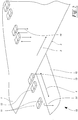
- the Figure 1 shows a three-dimensional schematic representation of a first embodiment of the subject matter of the invention.
- a material web 1 moves along a running direction 2 and has an edge 3.
- the position of the edge 3 in a detection direction 4 extending perpendicular to the running direction 2 is detected by a sensor 10.
- the sensor 10 has a multiplicity of active elements 11, some of which are designed as transmitters 12 and others as receivers 13.
- the transmitters 12 can emit waves 14, in particular in the form of light, while the receivers 13 can receive these waves 14 and convert them into an electrical signal. If the web 1 is located between a transmitter 12 and a receiver 13, the waves 14 are shaded by the web 1, whereby the position of the edge 3 of the web 1 can be roughly determined.
- the electrical signal generated by the receiver 13 is also evaluated analogously in terms of its signal level. It must be taken into account that the detected signal becomes smaller, the more the material web 1 covers the radiation path between the transmitter 12 and the receiver 13. In this way, the sensor 10 can detect the position of the edge 3 of the material web 1 with high spatial resolution, which is in particular much more precise than the points defined by the individual active elements 11.
- the sensor 10 not only evaluates the direct radiation paths from a transmitter 12 to the opposite receiver 13; rather, radiation paths to various receivers 13 are also taken into account.
- the Figure 2 shows an alternative embodiment, wherein the same reference numerals designate the same parts.
- the transmitters 12 and receivers 13 are on the same side of the material web 1.
- the receivers 13 detect the waves 14 reflected by the material web 1.
- the same effects result as in the embodiment according to FIG Figure 1 .
- the only essential difference is that each recipient is now 13 exactly a corresponding electrical signal is then generated when the material web 1 lies in the radiation path between the transmitter 12 and the receiver 13.
- an optional reflector 15 is also shown, which is used in particular in the case of non-reflective or poorly reflective webs 1. This reflector 15 ensures a reflection of the waves 14, provided that the radiation path is not covered by the web 1.
- FIG. 11 shows a further alternative embodiment according to FIG Figure 2 Again, the same reference numerals designate the same parts. In the following, only the differences from the embodiment according to FIG Figure 2 received.
- each active element 11 has a dual function and is transmitter 12 and receiver 13 at the same time. This measure is particularly advantageous when the waves 14 are ultrasonic waves.
- FIG. 4 The mode of operation of the sensor 10 is explained in more detail with the aid of the illustration according to FIG Figure 4 .
- This representation corresponds to a view of the sensor 10 according to FIG Figure 1 in the direction of the running direction 2, so that the detection direction 4 in the Figure 4 is a horizontal line in the plane of the drawing.
- the active elements 11 are numbered in such a way that neighboring active elements 11 also receive neighboring ordinal numbers.
- the upper active elements 11 are always the transmitters 12, while the lower active elements 11 are the receivers 13.
- first transmitter 21 If one now looks at a first transmitter 21, one can see that a sensitive evaluation of the edge position of the material web 1 is basically only possible in an area that lies within the widths 16 between the first transmitter 21 and a first receiver 31.
- a second transmitter 22 is attached at a first distance 41 from the first transmitter 21, which corresponds at most to twice the mean value of the widths 16, there is a gap between the first transmitter 21 and the second transmitter 22 that is not shared by the first transmitter 21 and the first receiver 31 can still be measured by the second transmitter 22 and second receiver 32. This gap is closed in that the first transmitter 21 is also evaluated by the second receiver 32.
- the second transmitter 22 can also be evaluated by the first receiver 31. It can be seen that this measure closes the previously described gap in the detection area. However, this only works if the first distance 41 is not greater than twice the mean value of the widths 16 of the elements 11 mentioned.
- the first and second transmitters 21, 22 and the first and second receivers 31, 32 are understood as a group 51 in the following.
- An essentially identically structured group 52 consists of a third transmitter 23 and a fourth transmitter 24, as well as a third receiver 33 and fourth receiver 34, which are arranged at a mutual third spacing 43 which essentially corresponds to the first spacing 41.
- the second and third transmitters 22, 23 are, however, arranged at a significantly larger second distance 42 from one another. This results in a correspondingly enlarged gap between the two groups 51, 52 which cannot be directly detected by the active elements 11.
- this gap can be closed by evaluating the individual transmitters 12 and receivers 13 alternately.
- the gap area adjoining the second transmitter 22 becomes, for example covered by evaluating the first receiver 31 with the third transmitter 23 switched on.
- the first transmitter 21 could also be used together with the third receiver 33.
- the next gap area is covered by the pairing of third transmitters 23 and second receivers 32.
- the second transmitter 22 and the third receiver 33 can again be used here.
- the last area of the gap is finally covered by the second transmitter 22 and the fourth receiver 34.
- the fourth transmitter 24 and the second receiver 32 can again be used here. In this way, the entire gap between the two groups 51, 52 is covered, provided that the second distance 42 is not greater than twice the first distance 41.
- the gap between the third transmitter 23 and the fourth transmitter 24 is covered in the same way as between the first transmitter 21 and the second transmitter 22.
- the groups 51, 52 in turn form a group 53, which is followed by a further group 54.
- a fifth transmitter 25 and a fifth receiver 35 are provided in this group 54, the groups 53, 54 being at a fifth distance 45, which in particular corresponds to 9 times the first distance 41.
- This fifth transmitter 25 is followed by further active elements 11 in the same way as the arrangement described so far.
- the gap in the fifth distance 45 is also covered in a corresponding manner by the mutual use of transmitters 12 and receivers 13.
- this arrangement can be expanded in any way, so that the groups defined according to the above construction principle are always placed side by side in pairs and the distance between these groups with each group order by a factor of at least 2.2, at most by a factor of 4.0, in particular is increased by a factor of 3.0.
- this Cantor arrangement cannot be continued indefinitely, since the transmitters 12 can generally only emit in a restricted angular range and the receivers 13 can also only receive waves from a restricted angular range.
- this arrangement results in a considerable reduction in active elements 11, so that either fewer active elements 11 have to be installed or the existing active elements 11 can be distributed over a larger detection area.
- the new arrangement of the active elements 11 does not result in any gaps in the detection area. Such gaps arise only in the vicinity of the plane of the active elements 11, but this is irrelevant for the position of the web 1.
- the transmitters 12 have widths 16 over which they can emit waves 14 with relevant power.
- the receivers 13 can convert the waves 14 over the width 16 into a metrologically relevant electrical signal.
- This fact is in accordance with the diagram below Figure 5 shown.
- This diagram shows the radiation characteristic of the transmitter 12 as a function of the location in the transmitter 12.
- the transmitter 12 has a component width 17.
- the radiation characteristic shows that the transmitter 12 is not metrologically relevant in the edge areas Radiation intensity has more, because there is an unacceptable signal-to-noise ratio in the edge areas.
- the width 16 of the transmitter 12 is determined by the flanks of the radiation characteristic. How the width 16 is specifically defined only plays a subordinate role for the subject matter of the invention.
- the turning point of the emission characteristic could be used as the limit for the width 16.
- a certain ratio between the local emission characteristic and the emission characteristic in the peak could also be used, for example the halving point or the 1 / e point of the emission characteristic.
- the receiver 13 in which case, instead of the radiation characteristic, the ratio between the electrical signal generated by the receiver 13 and the radiated wave power is used. If the active elements 11 are equipped with means influencing the waves 14, such as lenses, diffusers or diffraction slits, then these means must be taken into account when determining the width.
Landscapes
- Physics & Mathematics (AREA)
- Engineering & Computer Science (AREA)
- Remote Sensing (AREA)
- Radar, Positioning & Navigation (AREA)
- General Physics & Mathematics (AREA)
- Computer Networks & Wireless Communication (AREA)
- Electromagnetism (AREA)
- Analytical Chemistry (AREA)
- Immunology (AREA)
- Pathology (AREA)
- General Health & Medical Sciences (AREA)
- Biochemistry (AREA)
- Chemical & Material Sciences (AREA)
- Life Sciences & Earth Sciences (AREA)
- Health & Medical Sciences (AREA)
- Acoustics & Sound (AREA)
- Geophysics And Detection Of Objects (AREA)
- Length Measuring Devices With Unspecified Measuring Means (AREA)
- Measurement Of Velocity Or Position Using Acoustic Or Ultrasonic Waves (AREA)
Claims (15)
- Capteur permettant de détecter au moins un bord (3) d'au moins une bande de matière (1) se déplaçant dans un sens machine (2), le capteur (10) présentant des éléments actifs (11) qui sont disposés côte à côte dans au moins une direction de détection (4) s'étendant transversalement au sens machine (2) de ladite au moins une bande de matière (1), et les éléments actifs (11) étant formés par des émetteurs (12) et des récepteurs (13), les émetteurs (12) pouvant émettre des ondes (14) et les récepteurs (13) pouvant recevoir les ondes (14), et la bande de matière (1) étant prévue pour influencer les ondes (14) sur le trajet de rayonnement entre les émetteurs (12) et les récepteurs (13), un premier (21, 31) et un deuxième (22, 32) des éléments actifs (11) étant voisins dans la direction de détection (4), et présentant une première distance mutuelle (41) dans la direction de détection (4),
caractérisé en ce que le deuxième (22, 32) et un troisième (23, 33) des éléments actifs (11) sont voisins dans la direction de détection (4) et présentent une deuxième distance mutuelle (42) dans la direction de détection (4) qui correspond à au moins 1,2 fois la première distance (41), et le troisième (23, 33) et un quatrième (24, 34) des éléments actifs (11) sont disposés de façon adjacente dans la direction de détection (4), une troisième distance mutuelle entre le troisième (23, 33) et le quatrième (24, 34) des éléments actifs (11) dans la direction de détection (4) correspondant au plus à 1,1 fois la première distance (41). - Capteur selon la revendication 1, caractérisé en ce que le premier (21, 31) et le deuxième (22, 32) des éléments actifs (11) constituent un groupe (51), et le troisième (23, 33) et le quatrième (24, 34) des éléments actifs (11) constituent un groupe (52), les groupes (51, 52) présentant une quatrième distance mutuelle (44) qui est au moins égale à 2,2 fois la première distance (41).
- Capteur selon la revendication 2, caractérisé en ce que des groupes (53, 54) d'un ordre supérieur parmi les groupes (51, 52) présentent une cinquième distance mutuelle (45) qui correspond à au moins 2,2 fois la distance des groupes (51, 52).
- Capteur selon la revendication 3, caractérisé en ce que la revendication 4 est applicable itérativement en ce que des groupes (53, 54) sont réunis en groupes d'ordre supérieur qui présentent à leur tour une distance mutuelle qui correspond au moins à 2,2 fois la distance des groupes (53, 54) de l'ordre inférieur.
- Capteur selon au moins l'une des revendications 1 à 4, caractérisé en ce qu'au moins l'un des éléments actifs (11) présente une largeur (16) qui correspond à au moins la moitié de la première distance (41).
- Capteur selon au moins l'une des revendications 1 à 5, caractérisé en ce que les largeurs (16) des émetteurs (12) sont identiques.
- Capteur selon au moins l'une des revendications 1 à 6, caractérisé en ce que les largeurs (16) des récepteurs (13) sont identiques.
- Capteur selon au moins l'une des revendications 1 à 7, caractérisé en ce que les largeurs (16) des éléments actifs (11) sont identiques.
- Capteur selon au moins l'une des revendications 1 à 8, caractérisé en ce que les émetteurs (12) et les récepteurs (13) se font face respectivement.
- Capteur selon au moins l'une des revendications 1 à 9, caractérisé en ce qu'au moins une partie des éléments actifs (11), vue dans la direction de détection (4), est disposée sous forme de trame.
- Capteur selon au moins l'une des revendications 1 à 10, caractérisé en ce qu'au moins une partie des éléments actifs (11) présente un agencement selon un ensemble de Cantor tronqué.
- Capteur selon au moins l'une des revendications 1 à 11, caractérisé en ce que les ondes (14) sont des ondes électromagnétiques.
- Capteur selon au moins l'une des revendications 1 à 12, caractérisé en ce que les ondes (14) sont des ondes sonores.
- Capteur selon au moins l'une des revendications 1 à 13, caractérisé en ce qu'au moins l'un des éléments actifs (11) est un émetteur (12) et un récepteur (13).
- Capteur selon au moins l'une des revendications 1 à 14, caractérisé en ce que le capteur (10) peut détecter ledit au moins un bord (3) dans la direction de détection (4) et/ou transversalement à celle-ci.
Applications Claiming Priority (1)
| Application Number | Priority Date | Filing Date | Title |
|---|---|---|---|
| DE102017010880.3A DE102017010880A1 (de) | 2017-11-24 | 2017-11-24 | Sensor zum Erfassen mindestens einer Kante einer laufenden Warenbahn |
Publications (2)
| Publication Number | Publication Date |
|---|---|
| EP3489179A1 EP3489179A1 (fr) | 2019-05-29 |
| EP3489179B1 true EP3489179B1 (fr) | 2021-06-16 |
Family
ID=64426623
Family Applications (1)
| Application Number | Title | Priority Date | Filing Date |
|---|---|---|---|
| EP18000914.4A Active EP3489179B1 (fr) | 2017-11-24 | 2018-11-20 | Capteur de détection d'au moins un bord d'une bande de matière continue |
Country Status (5)
| Country | Link |
|---|---|
| US (1) | US11097916B2 (fr) |
| EP (1) | EP3489179B1 (fr) |
| KR (1) | KR102626781B1 (fr) |
| CN (1) | CN109835756B (fr) |
| DE (1) | DE102017010880A1 (fr) |
Families Citing this family (3)
| Publication number | Priority date | Publication date | Assignee | Title |
|---|---|---|---|---|
| DE102020104931B4 (de) * | 2020-02-25 | 2021-11-18 | Balluff Gmbh | Verfahren und Vorrichtung zur Kantenerkennung eines Objekts |
| CN113091664B (zh) * | 2021-04-01 | 2023-04-18 | 佛山市恒溢彩印有限公司 | 一种宽度检测方法、系统、终端及存储介质 |
| CN116986377A (zh) * | 2023-08-10 | 2023-11-03 | 上海百琪迈科技(集团)有限公司 | 一种应用于布料裁切机的纠偏装置 |
Family Cites Families (11)
| Publication number | Priority date | Publication date | Assignee | Title |
|---|---|---|---|---|
| DE3900928C1 (fr) | 1989-01-14 | 1990-06-21 | Erhardt + Leimer Gmbh, 8900 Augsburg, De | |
| WO1997008761A1 (fr) * | 1995-08-28 | 1997-03-06 | Accuweb, Inc. | Unites de transducteurs a ultrasons pour detection du bord d'un ruban |
| US6175419B1 (en) * | 1999-03-24 | 2001-01-16 | Fife Corporation | Light sensor for web-guiding apparatus |
| DE19924798C1 (de) * | 1999-05-29 | 2001-01-11 | Erhardt & Leimer Gmbh | Verfahren und Vorrichtung zur Lageerfassung einer Kante von einer laufenden Warenbahn |
| DE10337673B3 (de) * | 2003-08-16 | 2005-04-28 | Erhardt & Leimer Gmbh | Verfahren und Vorrichtung zum Erfassen der Lage einer Kante einer laufenden Warenbahn |
| US7415881B2 (en) * | 2004-08-19 | 2008-08-26 | Fife Corporation | Ultrasonic sensor system for web-guiding apparatus |
| DE102007060080A1 (de) * | 2007-12-13 | 2009-06-25 | Giesecke & Devrient Gmbh | Verfahren und Vorrichtung für die Überwachung der Vereinzelung von Blattgut |
| JP4960466B2 (ja) * | 2010-03-18 | 2012-06-27 | 株式会社東芝 | 紙葉類処理装置 |
| JP5825925B2 (ja) * | 2011-08-19 | 2015-12-02 | キヤノン株式会社 | 位置検知装置及び画像形成装置 |
| DE202012004305U1 (de) * | 2012-04-27 | 2012-05-25 | Texmag Gmbh Vertriebsgesellschaft | Vorrichtung zum Detektieren einer Kante einer Materialbahn |
| CN103130005B (zh) * | 2013-02-25 | 2015-06-24 | 西安理工大学 | 一种基于红外光的带材自动对中检测方法 |
-
2017
- 2017-11-24 DE DE102017010880.3A patent/DE102017010880A1/de not_active Withdrawn
-
2018
- 2018-11-16 US US16/192,857 patent/US11097916B2/en active Active
- 2018-11-20 EP EP18000914.4A patent/EP3489179B1/fr active Active
- 2018-11-21 KR KR1020180144387A patent/KR102626781B1/ko active Active
- 2018-11-23 CN CN201811402115.8A patent/CN109835756B/zh active Active
Also Published As
| Publication number | Publication date |
|---|---|
| CN109835756B (zh) | 2022-06-17 |
| US20190161309A1 (en) | 2019-05-30 |
| EP3489179A1 (fr) | 2019-05-29 |
| US11097916B2 (en) | 2021-08-24 |
| CN109835756A (zh) | 2019-06-04 |
| KR102626781B1 (ko) | 2024-01-17 |
| KR20190060690A (ko) | 2019-06-03 |
| DE102017010880A1 (de) | 2019-05-29 |
Similar Documents
| Publication | Publication Date | Title |
|---|---|---|
| DE2428333C3 (de) | Pyroelektrischer Detektor für Wärmestrahlung | |
| EP2453252B1 (fr) | Capteur 3D à économie d'énergie | |
| DE102018113476B4 (de) | Vorrichtung und verfahren zur drehmomentmessung | |
| DE2238413A1 (de) | Elektrooptische anzeigevorrichtung fuer differentiale bewegungen und positionen | |
| EP2933655A1 (fr) | Capteur optoélectronique et procédé destiné à la détection d'objets dans une zone de surveillance | |
| WO2002011075A1 (fr) | Dispositif de comptage de personnes | |
| EP2657645B1 (fr) | Dispositif de détection d'un bord d'une bande de matériau | |
| EP3489179A1 (fr) | Capteur de détection d'au moins un bord d'une bande de matière continue | |
| DE102022206522A1 (de) | Positionssensor und positionscodierer, die millimeterwellenmetamaterial mit einem millimeterwellen- radar verwenden | |
| EP2631683A2 (fr) | Rideau lumineux | |
| EP2226652A1 (fr) | Capteur optoélectronique doté d'un émetteur à lampe d'orientation | |
| EP2888569B1 (fr) | Système de capteurs pour détecter un mouvement d'une source de lumière infrarouge | |
| EP2461188B1 (fr) | Capteur optoélectronique | |
| EP2593987A1 (fr) | Structure de conducteurs coaxiaux | |
| DE102020125896A1 (de) | Drehmoment-messung unter verwendung von millimeter-wellen-metamaterial | |
| WO2016128436A1 (fr) | Détecteur et système lidar | |
| DE3238883C2 (de) | Einrichtung zum Vermessen der Abmessung und/oder Lage eines durch sie bewegten Gegenstandes | |
| EP1058087B1 (fr) | Détermination de la position d'un bord avec des capteurs répartis par la détermination du point tournant | |
| DE102018117878A1 (de) | Sicherheitslichtgitter | |
| EP1980870B1 (fr) | Capteur optoélectronique et procédé de transmission blindée de signal | |
| EP2767389A1 (fr) | Presse à chaud à double bande | |
| EP2502087B1 (fr) | Dispositif et procédé de localisation de sources de rayonnement optique modulées | |
| EP2368143B1 (fr) | Barrière lumineuse | |
| EP3168655B1 (fr) | Barrières lumineuses et procédé de détection d'objets | |
| EP2040336B1 (fr) | Capteur de radar |
Legal Events
| Date | Code | Title | Description |
|---|---|---|---|
| PUAI | Public reference made under article 153(3) epc to a published international application that has entered the european phase |
Free format text: ORIGINAL CODE: 0009012 |
|
| STAA | Information on the status of an ep patent application or granted ep patent |
Free format text: STATUS: THE APPLICATION HAS BEEN PUBLISHED |
|
| AK | Designated contracting states |
Kind code of ref document: A1 Designated state(s): AL AT BE BG CH CY CZ DE DK EE ES FI FR GB GR HR HU IE IS IT LI LT LU LV MC MK MT NL NO PL PT RO RS SE SI SK SM TR |
|
| AX | Request for extension of the european patent |
Extension state: BA ME |
|
| STAA | Information on the status of an ep patent application or granted ep patent |
Free format text: STATUS: REQUEST FOR EXAMINATION WAS MADE |
|
| 17P | Request for examination filed |
Effective date: 20191121 |
|
| RBV | Designated contracting states (corrected) |
Designated state(s): AL AT BE BG CH CY CZ DE DK EE ES FI FR GB GR HR HU IE IS IT LI LT LU LV MC MK MT NL NO PL PT RO RS SE SI SK SM TR |
|
| GRAP | Despatch of communication of intention to grant a patent |
Free format text: ORIGINAL CODE: EPIDOSNIGR1 |
|
| STAA | Information on the status of an ep patent application or granted ep patent |
Free format text: STATUS: GRANT OF PATENT IS INTENDED |
|
| INTG | Intention to grant announced |
Effective date: 20210127 |
|
| GRAS | Grant fee paid |
Free format text: ORIGINAL CODE: EPIDOSNIGR3 |
|
| GRAA | (expected) grant |
Free format text: ORIGINAL CODE: 0009210 |
|
| STAA | Information on the status of an ep patent application or granted ep patent |
Free format text: STATUS: THE PATENT HAS BEEN GRANTED |
|
| AK | Designated contracting states |
Kind code of ref document: B1 Designated state(s): AL AT BE BG CH CY CZ DE DK EE ES FI FR GB GR HR HU IE IS IT LI LT LU LV MC MK MT NL NO PL PT RO RS SE SI SK SM TR |
|
| REG | Reference to a national code |
Ref country code: GB Ref legal event code: FG4D Free format text: NOT ENGLISH |
|
| REG | Reference to a national code |
Ref country code: CH Ref legal event code: EP |
|
| REG | Reference to a national code |
Ref country code: DE Ref legal event code: R096 Ref document number: 502018005696 Country of ref document: DE |
|
| REG | Reference to a national code |
Ref country code: AT Ref legal event code: REF Ref document number: 1402180 Country of ref document: AT Kind code of ref document: T Effective date: 20210715 |
|
| REG | Reference to a national code |
Ref country code: IE Ref legal event code: FG4D Free format text: LANGUAGE OF EP DOCUMENT: GERMAN |
|
| REG | Reference to a national code |
Ref country code: LT Ref legal event code: MG9D |
|
| PG25 | Lapsed in a contracting state [announced via postgrant information from national office to epo] |
Ref country code: HR Free format text: LAPSE BECAUSE OF FAILURE TO SUBMIT A TRANSLATION OF THE DESCRIPTION OR TO PAY THE FEE WITHIN THE PRESCRIBED TIME-LIMIT Effective date: 20210616 Ref country code: BG Free format text: LAPSE BECAUSE OF FAILURE TO SUBMIT A TRANSLATION OF THE DESCRIPTION OR TO PAY THE FEE WITHIN THE PRESCRIBED TIME-LIMIT Effective date: 20210916 Ref country code: LT Free format text: LAPSE BECAUSE OF FAILURE TO SUBMIT A TRANSLATION OF THE DESCRIPTION OR TO PAY THE FEE WITHIN THE PRESCRIBED TIME-LIMIT Effective date: 20210616 Ref country code: FI Free format text: LAPSE BECAUSE OF FAILURE TO SUBMIT A TRANSLATION OF THE DESCRIPTION OR TO PAY THE FEE WITHIN THE PRESCRIBED TIME-LIMIT Effective date: 20210616 |
|
| REG | Reference to a national code |
Ref country code: NL Ref legal event code: MP Effective date: 20210616 |
|
| PG25 | Lapsed in a contracting state [announced via postgrant information from national office to epo] |
Ref country code: GR Free format text: LAPSE BECAUSE OF FAILURE TO SUBMIT A TRANSLATION OF THE DESCRIPTION OR TO PAY THE FEE WITHIN THE PRESCRIBED TIME-LIMIT Effective date: 20210917 Ref country code: LV Free format text: LAPSE BECAUSE OF FAILURE TO SUBMIT A TRANSLATION OF THE DESCRIPTION OR TO PAY THE FEE WITHIN THE PRESCRIBED TIME-LIMIT Effective date: 20210616 Ref country code: NO Free format text: LAPSE BECAUSE OF FAILURE TO SUBMIT A TRANSLATION OF THE DESCRIPTION OR TO PAY THE FEE WITHIN THE PRESCRIBED TIME-LIMIT Effective date: 20210916 Ref country code: SE Free format text: LAPSE BECAUSE OF FAILURE TO SUBMIT A TRANSLATION OF THE DESCRIPTION OR TO PAY THE FEE WITHIN THE PRESCRIBED TIME-LIMIT Effective date: 20210616 Ref country code: RS Free format text: LAPSE BECAUSE OF FAILURE TO SUBMIT A TRANSLATION OF THE DESCRIPTION OR TO PAY THE FEE WITHIN THE PRESCRIBED TIME-LIMIT Effective date: 20210616 |
|
| PG25 | Lapsed in a contracting state [announced via postgrant information from national office to epo] |
Ref country code: SM Free format text: LAPSE BECAUSE OF FAILURE TO SUBMIT A TRANSLATION OF THE DESCRIPTION OR TO PAY THE FEE WITHIN THE PRESCRIBED TIME-LIMIT Effective date: 20210616 Ref country code: SK Free format text: LAPSE BECAUSE OF FAILURE TO SUBMIT A TRANSLATION OF THE DESCRIPTION OR TO PAY THE FEE WITHIN THE PRESCRIBED TIME-LIMIT Effective date: 20210616 Ref country code: ES Free format text: LAPSE BECAUSE OF FAILURE TO SUBMIT A TRANSLATION OF THE DESCRIPTION OR TO PAY THE FEE WITHIN THE PRESCRIBED TIME-LIMIT Effective date: 20210616 Ref country code: EE Free format text: LAPSE BECAUSE OF FAILURE TO SUBMIT A TRANSLATION OF THE DESCRIPTION OR TO PAY THE FEE WITHIN THE PRESCRIBED TIME-LIMIT Effective date: 20210616 Ref country code: CZ Free format text: LAPSE BECAUSE OF FAILURE TO SUBMIT A TRANSLATION OF THE DESCRIPTION OR TO PAY THE FEE WITHIN THE PRESCRIBED TIME-LIMIT Effective date: 20210616 Ref country code: PT Free format text: LAPSE BECAUSE OF FAILURE TO SUBMIT A TRANSLATION OF THE DESCRIPTION OR TO PAY THE FEE WITHIN THE PRESCRIBED TIME-LIMIT Effective date: 20211018 Ref country code: RO Free format text: LAPSE BECAUSE OF FAILURE TO SUBMIT A TRANSLATION OF THE DESCRIPTION OR TO PAY THE FEE WITHIN THE PRESCRIBED TIME-LIMIT Effective date: 20210616 Ref country code: NL Free format text: LAPSE BECAUSE OF FAILURE TO SUBMIT A TRANSLATION OF THE DESCRIPTION OR TO PAY THE FEE WITHIN THE PRESCRIBED TIME-LIMIT Effective date: 20210616 |
|
| PG25 | Lapsed in a contracting state [announced via postgrant information from national office to epo] |
Ref country code: PL Free format text: LAPSE BECAUSE OF FAILURE TO SUBMIT A TRANSLATION OF THE DESCRIPTION OR TO PAY THE FEE WITHIN THE PRESCRIBED TIME-LIMIT Effective date: 20210616 |
|
| REG | Reference to a national code |
Ref country code: DE Ref legal event code: R097 Ref document number: 502018005696 Country of ref document: DE |
|
| PLBE | No opposition filed within time limit |
Free format text: ORIGINAL CODE: 0009261 |
|
| STAA | Information on the status of an ep patent application or granted ep patent |
Free format text: STATUS: NO OPPOSITION FILED WITHIN TIME LIMIT |
|
| PG25 | Lapsed in a contracting state [announced via postgrant information from national office to epo] |
Ref country code: DK Free format text: LAPSE BECAUSE OF FAILURE TO SUBMIT A TRANSLATION OF THE DESCRIPTION OR TO PAY THE FEE WITHIN THE PRESCRIBED TIME-LIMIT Effective date: 20210616 |
|
| 26N | No opposition filed |
Effective date: 20220317 |
|
| PG25 | Lapsed in a contracting state [announced via postgrant information from national office to epo] |
Ref country code: AL Free format text: LAPSE BECAUSE OF FAILURE TO SUBMIT A TRANSLATION OF THE DESCRIPTION OR TO PAY THE FEE WITHIN THE PRESCRIBED TIME-LIMIT Effective date: 20210616 |
|
| PG25 | Lapsed in a contracting state [announced via postgrant information from national office to epo] |
Ref country code: MC Free format text: LAPSE BECAUSE OF FAILURE TO SUBMIT A TRANSLATION OF THE DESCRIPTION OR TO PAY THE FEE WITHIN THE PRESCRIBED TIME-LIMIT Effective date: 20210616 |
|
| REG | Reference to a national code |
Ref country code: CH Ref legal event code: PL |
|
| PG25 | Lapsed in a contracting state [announced via postgrant information from national office to epo] |
Ref country code: LU Free format text: LAPSE BECAUSE OF NON-PAYMENT OF DUE FEES Effective date: 20211120 Ref country code: BE Free format text: LAPSE BECAUSE OF NON-PAYMENT OF DUE FEES Effective date: 20211130 |
|
| REG | Reference to a national code |
Ref country code: BE Ref legal event code: MM Effective date: 20211130 |
|
| PG25 | Lapsed in a contracting state [announced via postgrant information from national office to epo] |
Ref country code: IE Free format text: LAPSE BECAUSE OF NON-PAYMENT OF DUE FEES Effective date: 20211120 |
|
| PG25 | Lapsed in a contracting state [announced via postgrant information from national office to epo] |
Ref country code: CY Free format text: LAPSE BECAUSE OF FAILURE TO SUBMIT A TRANSLATION OF THE DESCRIPTION OR TO PAY THE FEE WITHIN THE PRESCRIBED TIME-LIMIT Effective date: 20210616 |
|
| GBPC | Gb: european patent ceased through non-payment of renewal fee |
Effective date: 20221120 |
|
| PG25 | Lapsed in a contracting state [announced via postgrant information from national office to epo] |
Ref country code: LI Free format text: LAPSE BECAUSE OF NON-PAYMENT OF DUE FEES Effective date: 20220630 Ref country code: HU Free format text: LAPSE BECAUSE OF FAILURE TO SUBMIT A TRANSLATION OF THE DESCRIPTION OR TO PAY THE FEE WITHIN THE PRESCRIBED TIME-LIMIT; INVALID AB INITIO Effective date: 20181120 Ref country code: CH Free format text: LAPSE BECAUSE OF NON-PAYMENT OF DUE FEES Effective date: 20220630 |
|
| PG25 | Lapsed in a contracting state [announced via postgrant information from national office to epo] |
Ref country code: GB Free format text: LAPSE BECAUSE OF NON-PAYMENT OF DUE FEES Effective date: 20221120 |
|
| PG25 | Lapsed in a contracting state [announced via postgrant information from national office to epo] |
Ref country code: MK Free format text: LAPSE BECAUSE OF FAILURE TO SUBMIT A TRANSLATION OF THE DESCRIPTION OR TO PAY THE FEE WITHIN THE PRESCRIBED TIME-LIMIT Effective date: 20210616 |
|
| PG25 | Lapsed in a contracting state [announced via postgrant information from national office to epo] |
Ref country code: MT Free format text: LAPSE BECAUSE OF FAILURE TO SUBMIT A TRANSLATION OF THE DESCRIPTION OR TO PAY THE FEE WITHIN THE PRESCRIBED TIME-LIMIT Effective date: 20210616 |
|
| REG | Reference to a national code |
Ref country code: AT Ref legal event code: MM01 Ref document number: 1402180 Country of ref document: AT Kind code of ref document: T Effective date: 20231120 |
|
| PG25 | Lapsed in a contracting state [announced via postgrant information from national office to epo] |
Ref country code: AT Free format text: LAPSE BECAUSE OF NON-PAYMENT OF DUE FEES Effective date: 20231120 |
|
| PG25 | Lapsed in a contracting state [announced via postgrant information from national office to epo] |
Ref country code: AT Free format text: LAPSE BECAUSE OF NON-PAYMENT OF DUE FEES Effective date: 20231120 |
|
| PGFP | Annual fee paid to national office [announced via postgrant information from national office to epo] |
Ref country code: IT Payment date: 20251127 Year of fee payment: 8 |
|
| PGFP | Annual fee paid to national office [announced via postgrant information from national office to epo] |
Ref country code: FR Payment date: 20251128 Year of fee payment: 8 |
|
| PGFP | Annual fee paid to national office [announced via postgrant information from national office to epo] |
Ref country code: TR Payment date: 20251110 Year of fee payment: 8 |
|
| PGFP | Annual fee paid to national office [announced via postgrant information from national office to epo] |
Ref country code: DE Payment date: 20260116 Year of fee payment: 8 |
|
| PGFP | Annual fee paid to national office [announced via postgrant information from national office to epo] |
Ref country code: AT Payment date: 20260410 Year of fee payment: 5 |