EP3489202B1 - Verfahren und vorrichtung zur herstellung einer glasscheibe für eine glasscheibeneinheit - Google Patents
Verfahren und vorrichtung zur herstellung einer glasscheibe für eine glasscheibeneinheit Download PDFInfo
- Publication number
- EP3489202B1 EP3489202B1 EP17830886.2A EP17830886A EP3489202B1 EP 3489202 B1 EP3489202 B1 EP 3489202B1 EP 17830886 A EP17830886 A EP 17830886A EP 3489202 B1 EP3489202 B1 EP 3489202B1
- Authority
- EP
- European Patent Office
- Prior art keywords
- glass
- glass panel
- spacer
- frame member
- disposition
- Prior art date
- Legal status (The legal status is an assumption and is not a legal conclusion. Google has not performed a legal analysis and makes no representation as to the accuracy of the status listed.)
- Active
Links
Images







Classifications
-
- C—CHEMISTRY; METALLURGY
- C03—GLASS; MINERAL OR SLAG WOOL
- C03B—MANUFACTURE, SHAPING, OR SUPPLEMENTARY PROCESSES
- C03B23/00—Re-forming shaped glass
- C03B23/20—Uniting glass pieces by fusing without substantial reshaping
- C03B23/203—Uniting glass sheets
-
- C—CHEMISTRY; METALLURGY
- C03—GLASS; MINERAL OR SLAG WOOL
- C03B—MANUFACTURE, SHAPING, OR SUPPLEMENTARY PROCESSES
- C03B18/00—Shaping glass in contact with the surface of a liquid
- C03B18/02—Forming sheets
-
- C—CHEMISTRY; METALLURGY
- C03—GLASS; MINERAL OR SLAG WOOL
- C03B—MANUFACTURE, SHAPING, OR SUPPLEMENTARY PROCESSES
- C03B23/00—Re-forming shaped glass
- C03B23/20—Uniting glass pieces by fusing without substantial reshaping
- C03B23/24—Making hollow glass sheets or bricks
- C03B23/245—Hollow glass sheets
-
- C—CHEMISTRY; METALLURGY
- C03—GLASS; MINERAL OR SLAG WOOL
- C03B—MANUFACTURE, SHAPING, OR SUPPLEMENTARY PROCESSES
- C03B25/00—Annealing glass products
- C03B25/02—Annealing glass products in a discontinuous way
- C03B25/025—Glass sheets
-
- C—CHEMISTRY; METALLURGY
- C03—GLASS; MINERAL OR SLAG WOOL
- C03C—CHEMICAL COMPOSITION OF GLASSES, GLAZES OR VITREOUS ENAMELS; SURFACE TREATMENT OF GLASS; SURFACE TREATMENT OF FIBRES OR FILAMENTS MADE FROM GLASS, MINERALS OR SLAGS; JOINING GLASS TO GLASS OR OTHER MATERIALS
- C03C27/00—Joining pieces of glass to pieces of other inorganic material; Joining glass to glass other than by fusing
- C03C27/02—Joining pieces of glass to pieces of other inorganic material; Joining glass to glass other than by fusing by fusing glass directly to metal
-
- C—CHEMISTRY; METALLURGY
- C03—GLASS; MINERAL OR SLAG WOOL
- C03C—CHEMICAL COMPOSITION OF GLASSES, GLAZES OR VITREOUS ENAMELS; SURFACE TREATMENT OF GLASS; SURFACE TREATMENT OF FIBRES OR FILAMENTS MADE FROM GLASS, MINERALS OR SLAGS; JOINING GLASS TO GLASS OR OTHER MATERIALS
- C03C27/00—Joining pieces of glass to pieces of other inorganic material; Joining glass to glass other than by fusing
- C03C27/06—Joining glass to glass by processes other than fusing
- C03C27/10—Joining glass to glass by processes other than fusing with the aid of adhesive specially adapted for that purpose
-
- E—FIXED CONSTRUCTIONS
- E06—DOORS, WINDOWS, SHUTTERS, OR ROLLER BLINDS IN GENERAL; LADDERS
- E06B—FIXED OR MOVABLE CLOSURES FOR OPENINGS IN BUILDINGS, VEHICLES, FENCES OR LIKE ENCLOSURES IN GENERAL, e.g. DOORS, WINDOWS, BLINDS, GATES
- E06B3/00—Window sashes, door leaves, or like elements for closing wall or like openings; Layout of fixed or moving closures, e.g. windows in wall or like openings; Features of rigidly-mounted outer frames relating to the mounting of wing frames
- E06B3/66—Units comprising two or more parallel glass or like panes permanently secured together
- E06B3/663—Elements for spacing panes
- E06B3/66304—Discrete spacing elements, e.g. for evacuated glazing units
-
- E—FIXED CONSTRUCTIONS
- E06—DOORS, WINDOWS, SHUTTERS, OR ROLLER BLINDS IN GENERAL; LADDERS
- E06B—FIXED OR MOVABLE CLOSURES FOR OPENINGS IN BUILDINGS, VEHICLES, FENCES OR LIKE ENCLOSURES IN GENERAL, e.g. DOORS, WINDOWS, BLINDS, GATES
- E06B3/00—Window sashes, door leaves, or like elements for closing wall or like openings; Layout of fixed or moving closures, e.g. windows in wall or like openings; Features of rigidly-mounted outer frames relating to the mounting of wing frames
- E06B3/66—Units comprising two or more parallel glass or like panes permanently secured together
- E06B3/673—Assembling the units
-
- E—FIXED CONSTRUCTIONS
- E06—DOORS, WINDOWS, SHUTTERS, OR ROLLER BLINDS IN GENERAL; LADDERS
- E06B—FIXED OR MOVABLE CLOSURES FOR OPENINGS IN BUILDINGS, VEHICLES, FENCES OR LIKE ENCLOSURES IN GENERAL, e.g. DOORS, WINDOWS, BLINDS, GATES
- E06B3/00—Window sashes, door leaves, or like elements for closing wall or like openings; Layout of fixed or moving closures, e.g. windows in wall or like openings; Features of rigidly-mounted outer frames relating to the mounting of wing frames
- E06B3/66—Units comprising two or more parallel glass or like panes permanently secured together
- E06B3/673—Assembling the units
- E06B3/67326—Assembling spacer elements with the panes
-
- E—FIXED CONSTRUCTIONS
- E06—DOORS, WINDOWS, SHUTTERS, OR ROLLER BLINDS IN GENERAL; LADDERS
- E06B—FIXED OR MOVABLE CLOSURES FOR OPENINGS IN BUILDINGS, VEHICLES, FENCES OR LIKE ENCLOSURES IN GENERAL, e.g. DOORS, WINDOWS, BLINDS, GATES
- E06B3/00—Window sashes, door leaves, or like elements for closing wall or like openings; Layout of fixed or moving closures, e.g. windows in wall or like openings; Features of rigidly-mounted outer frames relating to the mounting of wing frames
- E06B3/66—Units comprising two or more parallel glass or like panes permanently secured together
- E06B3/673—Assembling the units
- E06B3/67339—Working the edges of already assembled units
- E06B3/6736—Heat treatment
-
- E—FIXED CONSTRUCTIONS
- E06—DOORS, WINDOWS, SHUTTERS, OR ROLLER BLINDS IN GENERAL; LADDERS
- E06B—FIXED OR MOVABLE CLOSURES FOR OPENINGS IN BUILDINGS, VEHICLES, FENCES OR LIKE ENCLOSURES IN GENERAL, e.g. DOORS, WINDOWS, BLINDS, GATES
- E06B3/00—Window sashes, door leaves, or like elements for closing wall or like openings; Layout of fixed or moving closures, e.g. windows in wall or like openings; Features of rigidly-mounted outer frames relating to the mounting of wing frames
- E06B3/66—Units comprising two or more parallel glass or like panes permanently secured together
- E06B3/677—Evacuating or filling the gap between the panes ; Equilibration of inside and outside pressure; Preventing condensation in the gap between the panes; Cleaning the gap between the panes
- E06B3/6775—Evacuating or filling the gap during assembly
Definitions
- the present invention relates to a manufacturing method and a manufacturing apparatus of a glass panel for a glass panel unit.
- a glass panel unit which includes a pair of glass panels, a frame member disposed between the pair of glass panels to hermetically bind the pair of glass panels together, and spacers disposed in an inside space surrounded by the pair of glass panels and the frame member (see, for example, Patent Literature 1).
- Such a conventional glass panel unit is manufactured as follows. A pair of glass panels cut into a prescribed size is prepared, and a frame member and spacers are placed on one of the glass panels and are bound to the other glass panel. Then, an inside space is evacuated, heating is performed to soften the frame member once so as to hermetically bind the pair of glass panels together, thereby obtaining a finished product as the glass panel unit.
- US2012247063 A1 discloses a manufacturing method of a glass panel for a glass panel unit including the steps of glass melting, floating on molten metal for forming a sheet, annealing, and cutting, whereby after cutting spacers are disposed on the sheet using a laser beam.
- the conventional glass panel unit requires a process of disposing, for each cut glass panel, the spacers thereon with the spacers positioned, which is a troublesome process.
- Patent Literature 1 JP 2016-69232 A
- the present invention is a manufacturing method of a glass panel for a glass panel unit.
- the glass panel unit includes a pair of the glass panels facing each other with a prescribed distance therebetween, a frame member, an inside space, and a spacer.
- the frame member is disposed between the pair of glass panels to hermetically bind the pair of glass panels together.
- the inside space is surrounded by the pair of glass panels and the frame member.
- the spacer is in the inside space and is in contact with the pair of glass panels.
- the manufacturing method includes a melting step, a spreading step, an annealing step, a cutting step, and a spacer disposition step.
- the melting step is a step of melting a raw material of glass to produce melted glass.
- the spreading step is a step of spreading the melted glass onto melted metal to produce a glass sheet.
- the annealing step is a step of pulling out and annealing the glass sheet.
- the cutting step is a step of cutting the glass sheet annealed.
- the spacer disposition step is a step of disposing the spacer onto the glass sheet. The spacer disposition step is performed prior to the cutting step.
- the present invention is a manufacturing apparatus of a glass panel for a glass panel unit.
- the glass panel unit includes a pair of the glass panels facing each other with a prescribed distance therebetween, a frame member, an inside space, and a spacer.
- the frame member is disposed between the pair of glass panels to hermetically bind the pair of glass panels together.
- the inside space is surrounded by the pair of glass panels and the frame member.
- the spacer is in the inside space and is in contact with the pair of glass panels.
- the manufacturing apparatus includes, in order downstream of a flow of glass, a melting bath, a float bath, an annealing device, and a cutting device.
- the manufacturing apparatus includes a spacer disposition device disposed upstream of the cutting device.
- the melting bath is a device configured to melt a raw material of glass to produce melted glass.
- the float bath is a device configured to spread the melted glass onto melted metal to produce a glass sheet.
- the annealing device is a device configured to pull the glass sheet out of the float bath and anneal the glass sheet.
- the cutting device is a device configured to cut the glass sheet annealed.
- the spacer disposition device is a device configured to dispose the spacer onto the glass sheet.
- First to fourth embodiments below each relate to a manufacturing method and a manufacturing apparatus of a glass panel for a glass panel unit.
- a glass panel unit 1 (finished product) includes a pair of glass panels 2 facing each other with a prescribed distance therebetween, a frame member 3, an inside space 10, and spacers 4.
- the pair of glass panels 2 includes a first glass panel 21 and a second glass panel 22 facing each other with the prescribed distance therebetween.
- the frame member 3 is disposed between the pair of glass panels 2, that is, between the first glass panel 21 and the second glass panel 22 to hermetically bind the first glass panel 21 and the second glass panel 22 together.
- the inside space 10 surrounded by the first glass panel 21, the second glass panel 22, and the frame member 3 is formed.
- the spacers 4 are disposed in the inside space 10, are in contact with the first glass panel 21 and the second glass panel 22, and maintain the prescribed distance between the first glass panel 21 and the second glass panel 22.
- the glass panel unit 1 is manufactured by a glass panel manufacturing process of producing glass panels 2 and a unit manufacturing process of assembling the glass panels 2 thus produced into the glass panel unit 1 (finished product).
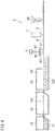
- the first embodiment features a manufacturing method and a manufacturing apparatus 5 applied for the glass panel manufacturing process (see FIG. 3 ). First, with reference to FIG. 3 , the manufacturing method and the manufacturing apparatus 5 of the glass panel 2 applied for the glass panel manufacturing process will be described.
- the manufacturing method of the glass panel 2 includes a melting step, a spreading step, an annealing step, a cutting step, and a spacer disposition step.
- the manufacturing apparatus 5 of the glass panel 2 includes a melting bath 51, a float bath 52, an annealing device 53, a cutting device 54, and a spacer disposition device 6.
- the melting step is a step of melting a raw material 11 of glass to produce melted glass.
- the melting step is performed in the melting bath 51 in which the raw material 11 of glass is melted.
- the melting bath 51 together with a heating means for melting the raw material 11 of glass and other apparatuses, forms a melting device.
- Examples of the raw material 11 of glass include sand, soda ash (sodium carbonate), dolomite, lime rock, and salt cake (sodium sulfate). Moreover, as the raw material 11 of glass, a coloring agent, a purifying agent, and a material for adjusting physical or chemical characteristics of the glass may be further added accordingly.
- the raw material 11 of glass is heated to about 1500°C to 1600°C by the heating means to become melted glass and is reserved in the melting bath 51.
- the spreading step is a step of spreading the melted glass melted in the melting step onto melted metal to produce a glass sheet 110.
- the spreading step is performed in the float bath 52 in which the melted glass is spread onto the melted metal.
- the float bath 52 together with a heating means for melting the metal and other apparatuses, form a float bath device.
- the float bath 52 reserves melted tin (not shown), and the melted glass spreads in a plate shape and gradually solidifies on an upper surface of the melted tin.
- the glass sheet 110 which has a uniform thickness and having a very flat surface.
- the annealing step is a step of pulling out and annealing the glass sheet 110.
- the annealing step is performed in the annealing device 53 in which the glass sheet 110 pulled out of the float bath 52 is annealed.
- the annealing device 53 includes a furnace 531 and a temperature adjustment device configured to adjust an ambient temperature in the furnace 531.
- a publicly known temperature adjustment device is available.
- the annealing device 53 includes rolls 532 and other necessary apparatuses such as a driving means thereof and transports the glass sheet 110 mounted on the rolls 532.
- the furnace 531 has a length (length in the transport direction of the glass sheet 110) of several tens of meters and a width (length in a direction orthogonal to the transport direction of the glass sheet 110) of about 10 m, but the length and the width are not limited to this embodiment.
- the glass sheet 110 has about 600°C to 750°C at an upstream end and about 200°C to 400°C at a downstream end, and the temperature linearly or non-linearly lowers from upstream to downstream between the upstream end and the downstream end.
- the cutting step is a step of cutting the glass sheet 110 which has been annealed.
- the cutting step is performed by the cutting device 54 configured to cut the glass sheet 110 which has been annealed.
- the cutting device 54 includes, for example, a cutting blade and other apparatuses such as a driving means.
- a publicly known cutting device is accordingly available.
- the melting bath 51, the float bath 52, the annealing device 53, and the cutting device 54 are provided in order downstream.
- upstream and downstream of a flow of glass are referred to as “upstream” and “downstream”, respectively. That is, the melted glass melted in the melting step then flows to the float bath 52, is thereafter transported to the annealing device 53, and is then transported to the cutting device 54, and thus, the melting step, the spreading step, the annealing step, and the cutting step are performed in this order.
- the manufacturing apparatus 5 of the glass panel 2 further includes a control device configured to control the melting device including the melting bath 51, the float bath device including the float bath 52, the annealing device 53, and the cutting device 54.
- the control device includes, for example, a so-called microcomputer configured to operate in accordance with a program.
- a publicly known control device is accordingly available.
- the manufacturing method (manufacturing method not including a spacer disposition step described later) and the manufacturing apparatus (manufacturing apparatus not including a spacer disposition device 6 described later) of the glass panel 2 described above are, in general, commonly included in publicly known manufacturing methods and manufacturing apparatuses of so-called float glass.
- publicly known general variations of such manufacturing methods and manufacturing apparatuses of float glass are accordingly available.
- the first embodiment features further inclusion of the spacer disposition step.
- the spacer disposition step is performed prior to the cutting step and is a step of disposing the spacers 4 onto the glass sheet 110.
- the spacer disposition step is performed by the spacer disposition device 6 configured to dispose the spacers 4 onto the glass sheet 110.
- the spacer disposition device 6 is disposed downstream of the annealing device 53 and upstream of the cutting device 54.
- the spacer disposition device 6 has a punching die 61 and a punch 62.
- the punching die 61 is located above the glass sheet 110 and has a through hole 611.
- the punching die 61 has an upper surface on which a sheet 63 is provided to cover the through hole 611.
- the sheet 63 is made of the same material as the spacer 4, has the same thickness as the spacer 4, and has a larger area than the spacer 4.
- the punch 62 is located above the punching die 61.
- the punch 62 has a columnar shape protruding downward and punches the sheet 63 provided on the punching die 61 downward through the through hole 611.
- the spacer disposition device 6 accordingly includes required apparatuses such as a driving means for driving the punch 62 and is controlled by the above-described control device.
- a publicly known device including such a punching die 61 and a punch 62 is accordingly available.
- a so-called chip mounter is available. Note that the spacer disposition device 6 is not limited to the device including the punching die 61 and the punch 62 and the chip mounter. For example, a device for performing so-called "pick and place" of picking up a spacer 4 stocked by a sucking head and placing it in a desired location onto a glass sheet may be provided.
- the raw material 11 of glass is first melted in the melting step to produce melted glass, the melted glass is then spread onto melted metal in the spreading step to produce the glass sheet 110, and thereafter, the glass sheet 110 is annealed in the annealing step.
- the spacers 4 are disposed on the glass sheet 110 in the spacer disposition step, and the glass sheet 110 is then cut in the cutting step.
- the second glass panel 22 having a surface provided with the spacers 4 is obtained.
- the first glass panel 21 is not provided with the spacers 4. That is, the first glass panel 21 is manufactured by a conventional glass panel manufacturing process including no spacer disposition step.
- the first glass panel 21 has a surface which faces the second glass panel 22 and which is provided with a coating 211 such as a so-called Low-E film, but the coating 211 does not have to be provided.
- the unit manufacturing process includes a disposition step, an assembling step, a hermetically sealing step, and a removal step.
- the disposition step is a step of forming the first glass panel 21, the second glass panel 22, the frame member 3, the inside space 10, an exhaust port, and a gas adsorbent 12.
- the disposition step includes first to fourth steps.
- the first step is a step (glass panel preparation step) of preparing the first glass panel 21 and the second glass panel 22.
- the second glass panel 22 As the second glass panel 22, the above-described glass panel 2 having the surface provided with the spacers 4 illustrated in FIG. 4 is used, and as the first glass panel 21, a glass panel 2 having a surface provided with no spacer 4 is used.
- the second step is a step (seal member forming step) of forming a seal (frame member 3).
- a material thermal adhesive as the frame member 3 is applied to the second glass panel 22 with a dispenser or the like.
- the frame member 3 includes a part formed as a low step part 31 having a smaller thickness than the other parts.
- the low step part 31 forms the exhaust port of a pre-fabricated component.
- an exhaust hole may be formed in the first glass panel 21 or the second glass panel 22.
- an exhaust pipe having an inner diameter larger than the exhaust hole is connected to the exhaust port by a well-known method adopting glass welding or melted metal serving as a welding member.
- a vacuum space may be formed by a so-called chip-off process of performing evacuation through the exhaust pipe and after an evacuation step, sealing a tip portion of the exhaust pipe to hermetically close a space.
- the third step is a step (gas adsorbent forming step) of forming the gas adsorbent 12.
- a solution containing powder of a getter dispersed therein is applied to a prescribed location on the second glass panel 22 and is dried, thereby forming the gas adsorbent 12.
- a gas adsorbent 12 containing powder of a getter may be formed into a pellet in a tablet shape in advance and may be disposed in a prescribed location on the second glass panel 22.
- a recess may be formed by scraping the surface of the second glass panel 22 in a shape matching the tablet shape, and the gas adsorbent 12 may be inserted in the recess.
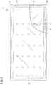
- the second glass panel 22 provided with the frame member 3, the gas adsorbent 12, the plurality of spacer 4 as illustrated in FIG. 5 is obtained.
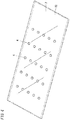
- the fourth step is a step (overlaying step) of disposing the first glass panel 21 and the second glass panel 22. As illustrated in FIG. 6 , in the fourth step, the first glass panel 21 is laid over the second glass panel 22 such that the first glass panel 21 and the second glass panel 22 are parallel to each other and face each other.
- the assembling step is a step (first melting step) of hermetically binding the first glass panel 21 and the second glass panel 22 with the frame member 3.
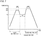
- the thermal adhesive is melted once at a prescribed temperature (first melting temperature) Tm1 higher than or equal to the softening point of the thermal adhesive to hermetically bind the first glass panel 21 and the second glass panel 22 together.
- the first glass panel 21 and the second glass panel 22 are disposed in a chamber and heated at the first melting temperature Tm1 for a predetermined time (first melting time) tm1.
- the above-described assembling step (first melting step) provides a pre-fabricated component 100 shown in FIG. 8 .
- the hermetically sealing step (the evacuation step and a melting step (second melting step)) is performed.
- the inside space 10 is evacuated through the exhaust port for a predetermined time (exhaust time) te during which only evacuation is performed at a prescribed temperature (exhaust temperature) Te, thereby creating a vacuum in the inside space 10.
- the thermal adhesive is melted once by being heated at a prescribed temperature (second melting temperature) Tm2 higher than or equal to the softening point for a predetermined time (second melting time) tm2, and thereby, the first glass panel 21 and the second glass panel 22 are pressed by atmospheric pressure and the thermal adhesive is compressed, so that the low step part 31 is closed. In this way, it is possible to from the seal (frame member 3) for maintaining the inside space 10 as a hermetically closed space. Note that the first melting temperature Tm1 is lower than the second melting temperature Tm2.
- the second melting step includes a time until the temperature increases from the prescribed temperature (exhaust temperature) Te to the prescribed temperature (second melting temperature) Tm2 and a time until the temperature decreases from the prescribed temperature (second melting temperature) Tm2 to the ordinary temperature.
- the inside space 10 is evacuated while the vacuum space is maintained.
- the glass panel manufacturing process includes the spacer disposition step. Therefore, the spacers 4 are disposed onto the glass panel 2 before the glass sheet 110 continuously produced is cut. Thus, the disposition of the spacers 4 can be performed as a part of the production process of the glass sheet 110 continuously produced. This, unlike the case where the spacers 4 are disposed after the cutting step, eliminates a troublesome process of disposing, for each glass panel 2, the spacers 4 thereon, with the spaces 4 positioned.
- the spacers 4 or the frame member 3 may be formed by application of a mixture of low melting glass and an organic binder with a dispenser. After the application and before cutting of the glass sheet 110, a re-heating step of performing re-heating to remove the organic binder may be performed.
- the re-heating step in order to remove the organic binder, the re-heating is performed to achieve at least a temperature (of about 100°C to 200°C) which is higher than or equal to the boiling point or the decomposition point of the organic binder, and in order to melt the low melting glass so as to fuse the first glass panel to the spacers 4 or to the frame member 3, the re-heating is performed to achieve a temperature (for example, higher than or equal to 400°C) which is higher than or equal to the melting point of the low melting glass.
- the re-heating step enables pretreatment of the spacers 4 or the frame member 3 before the cutting step, and therefore, the glass panel unit can be efficiently manufactured.
- the material for the spacers 4 is not limited to glass but may be, for example, metal or a resin.
- a manufacturing method and a manufacturing apparatus 5 of a glass panel 2 for a glass panel unit 1 according to a second embodiment will be described.
- the manufacturing method and the manufacturing apparatus 5 of the glass panel 2 for the glass panel unit 1 according to the second embodiment are the same as those in the first embodiment in large part. Therefore, components the same as those in the first embodiment are denoted by the same reference signs, the description thereof is omitted, and components different from those in the first embodiment are mainly described.
- the second embodiment includes a frame member disposition step of disposing a frame member 3 onto a glass sheet 110.
- the frame member disposition step is performed prior to the cutting step in the first embodiment.
- the frame member disposition step is performed by a frame member disposition device 7 configured to dispose the frame member 3 onto the glass sheet 110. That is, in the second embodiment, the manufacturing apparatus 5 of the glass panel 2 for the glass panel unit 1 further includes the frame member disposition device 7.
- the frame member disposition device 7 is disposed downstream of a spacer disposition device 6 and upstream of a cutting device 54 but may be disposed upstream of the spacer disposition device 6 and downstream of an annealing device 53.
- the frame member disposition device 7 includes a dispenser similar to that used in the second step (seal member forming step) of the disposition step of the unit manufacturing process in the first embodiment. Similarly to the seal member forming step, the frame member disposition device 7 applies a material (thermal adhesive) for the frame member 3 to a second glass panel 22.
- a disposition step in the second embodiment includes only a first step (glass panel preparation step), a third step (gas adsorbent forming step), and a fourth step (overlaying step).
- a raw material 11 of glass is first melted in a melting step to produce melted glass, the melted glass is then spread onto melted metal in a spreading step to produce the glass sheet 110, and thereafter, the glass sheet 110 is annealed in an annealing step.
- spacers 4 are disposed on the glass sheet 110 in a spacer disposition step, and the frame member 3 is thereafter disposed on the glass sheet 110 in the frame member disposition step, and the glass sheet 110 is then cut in a cutting step.
- the second glass panel 22 having a surface provided with the spacers 4 and the frame member 3.
- a first glass panel 21 is provided with neither the spacers 4 nor the frame member 3. That is, the first glass panel 21 is manufactured by a conventional glass panel manufacturing process including neither the spacer disposition step nor the frame member disposition step.
- a glass panel manufacturing process further includes the frame member disposition step. Therefore, disposition of the frame member 3 onto the glass panel 2 is performed before the glass sheet 110 continuously produced is cut. Thus, the disposition of the frame member 3 can be performed as a part of the production process of the glass sheet 110 continuously produced. This, unlike the case where the frame member 3 is disposed after the cutting step, eliminates a troublesome process of, disposing, for each glass panel 2, the frame member 3 thereon with the frame member 3 positioned.
- a manufacturing method and a manufacturing apparatus 5 of a glass panel 2 for a glass panel unit 1 according to a third embodiment will be described.
- the manufacturing method and the manufacturing apparatus 5 of the glass panel 2 for the glass panel unit 1 according to the third embodiment are the same as those in the first embodiment in large part. Therefore, components the same as those in the first embodiment are denoted by the same reference signs, the description thereof is omitted, and components different from those in the first embodiment are mainly described.
- the spacer disposition step is performed after the annealing step and before the cutting step.
- an annealing step includes a spacer disposition step.
- the spacer disposition step is a step of disposing spacers 4 by dropping hot-melt glass.
- a spacer disposition device 6 configured to perform the spacer disposition step is disposed in an annealing device 53.
- the spacer disposition device 6 is a device configured to dispose the spacers 4 by dropping the hot-melt glass serving as a material for the spacers 4.
- the hot-melt glass serving as the material for the spacers 4 is dropped onto a glass sheet 110 with the spacer disposition device 6 and cooled, thereby forming the spacers 4 at prescribed locations.
- a raw material 11 of glass is first melted in a melting step to produce melted glass, the melted glass is then spread onto melted metal in a spreading step to produce the glass sheet 110, and thereafter, the spacers 4 are disposed onto the glass sheet 110 in the spacer disposition step, while the glass sheet 110 is annealed in the annealing step.
- the glass sheet 110 is then cut in a cutting step.
- a second glass panel 22 having a surface provided with the spacers 4 is obtained.
- Subsequent unit manufacturing process is similar to that in the first embodiment.
- the annealing step includes the spacer disposition step. Therefore, while energy is saved by using residual heat of the annealing step, the spacers 4 can be easily formed.
- the melting point of the hot-melt glass serving as the material for the spacer 4 and the temperature in the annealing device 53 have to be taken into consideration.
- the difference between the melting point of the hot-melt glass serving as the material for the spacer 4 and the temperature of the glass sheet 110 at a location to which the hot-melt glass is dropped from the spacer disposition device 6 is smaller than or equal to 100°C.
- the hot-melt glass is preferably dropped onto the glass sheet 110 from the spacer disposition device 6 in an area at which the temperature in a furnace 531 is 700°C to 600°C.
- the location onto which the hot-melt glass is dropped is a location where the temperature of the glass sheet 110 is lower than the melting point of the hot-melt glass, a crack may be formed in the glass sheet 110 due to the temperature difference, and if the location onto which the hot-melt glass is dropped is a location where the temperature of the glass sheet 110 is higher than the melting point of the hot-melt glass, the spacers 4 may be broken.
- a manufacturing method and a manufacturing apparatus 5 of a glass panel 2 for a glass panel unit 1 according to a fourth embodiment will be described.
- the manufacturing method and the manufacturing apparatus 5 of the glass panel 2 for the glass panel unit 1 according to the fourth embodiment are the same as those in the second embodiment in large part. Therefore, components the same as those in the second embodiment are denoted by the same reference signs, the description thereof is omitted, and components different from those in the second embodiment are mainly described.
- the spacer disposition step is performed after the annealing step and before the cutting step.
- an annealing step includes a spacer disposition step.
- the spacer disposition step is a step of disposing spacers 4 by dropping hot-melt glass.
- the fourth embodiment is similar to the third embodiment, and a spacer disposition device 6 and a disposition location thereof are also similar to those in the third embodiment.
- a raw material 11 of glass is first melted in a melting step to produce melted glass, the melted glass is then spread onto melted metal in a spreading step to produce a glass sheet 110, and thereafter, the spacers 4 are disposed onto the glass sheet 110 in the spacer disposition step, while the glass sheet 110 is annealed in the annealing step.
- a frame member 3 is thereafter disposed on the glass sheet 110 in a frame member disposition step, and the glass sheet 110 is then cut in a cutting step. This provides a second glass panel 22 having a surface provided with the spacers 4 and the frame member 3 (see FIG. 10 ).
- Subsequent unit manufacturing process is similar to that in the third embodiment.
- the annealing step includes the spacer disposition step. Therefore, while energy is saved by using residual heat of the annealing step, the spacers 4 can be easily formed.
- the temperature of the glass sheet 110 in a location to which the hot-melt glass serving as a material for the spacers 4 is dropped is adjustable by changing a location (location in a transportation direction of the glass sheet 110) to which the hot-melt glass serving as the material for the spacers 4 is dropped.
- a manufacturing method of a glass panel 2 for a glass panel unit 1 of a first aspect includes a melting step, a spreading step, an annealing step, a cutting step, and a spacer disposition step.
- the glass panel unit 1 includes a pair of glass panels 2 disposed with a prescribed distance therebetween, a frame member 3, an inside space 10, and a spacer 4.
- the frame member 3 is disposed between the pair of glass panels 2 to hermetically bind the pair of glass panels 2 together.
- the inside space 10 is surrounded by the pair of glass panels 2 and the frame member 3.
- the spacer 4 is in the inside space 10 and is in contact with the pair of glass panels 2.
- the melting step is a step of melting a raw material 11 of glass to produce melted glass.
- the spreading step is a step of spreading the melted glass onto melted metal to produce a glass sheet 110.
- the annealing step is a step of pulling out and annealing the glass sheet 110.
- the cutting step is a step of cutting the glass sheet 110 annealed.
- the spacer disposition step is a step of disposing the spacer 4 onto the glass sheet 110. The spacer disposition step is performed prior to the cutting step.
- the manufacturing method of the glass panel 2 for the glass panel unit 1 of the first aspect includes the spacer disposition step. Therefore, the spacer 4 is disposed onto the glass panel 2 before the glass sheet 110 continuously produced is cut. Thus, the disposition of the spacer 4 can be performed as a part of the production process of the glass sheet 110 continuously produced. This, unlike the case where the spacer 4 is disposed after the cutting step, eliminates a troublesome process of disposing, for each glass panel 2, the spaces 4 thereon with the spacers 4 positioned.
- a manufacturing method of a glass panel 2 for a glass panel unit 1 of a second aspect of the present invention is additional and is realized in combination with the manufacturing method of the glass panel 2 for the glass panel unit 1 of the first aspect.
- the manufacturing method of the glass panel 2 for the glass panel unit 1 of the second aspect includes a frame member disposition step of disposing the frame member 3 onto the glass sheet 110.
- the frame member disposition step is performed prior to the cutting step.
- the manufacturing method of the glass panel 2 for the glass panel unit 1 of the second aspect further includes the frame member disposition step. Therefore, disposition of the frame member 3 onto the glass panel 2 is performed before the glass sheet 110 continuously produced is cut. Thus, the disposition of the frame member 3 can be performed as a part of the production process of the glass sheet 110 continuously produced. This, unlike the case where the frame member 3 is disposed after the cutting step, eliminates a troublesome process of disposing, for each glass panel 2, the frame member 3 thereon with the frame member 3 positioned.
- a manufacturing method of a glass panel 2 for a glass panel unit 1 of a third aspect of the present invention is additional and is realized in combination with the manufacturing method of the glass panel 2 for the glass panel unit 1 of the first or second aspect.
- the annealing step includes the spacer disposition step, and the spacer disposition step is a step of disposing the spacer 4 by dropping hot-melt glass serving as a material for the spacer 4.
- the annealing step includes the spacer disposition step. Therefore, while energy is saved by using residual heat of the annealing step, the spacer 4 can be easily formed.
- a manufacturing apparatus 5 of a glass panel 2 for a glass panel unit 1 includes, in order downstream of a flow of the glass, a melting bath 51, a float bath 52, an annealing device 53, and a cutting device 54.
- the manufacturing apparatus 5 includes a spacer disposition device 6 disposed upstream of the cutting device 54.
- the glass panel unit 1 includes a pair of glass panels 2 disposed with a prescribed distance therebetween, a frame member 3, an inside space 10, and a spacer 4.
- the frame member 3 is disposed between the pair of glass panels 2 to hermetically bind the pair of glass panels 2 together.
- the inside space 10 is surrounded by the pair of glass panels 2 and the frame member 3.
- the spacer 4 is in the inside space 10 and is in contact with the pair of glass panels 2.
- the melting bath 51 is a device in which a raw material 11 of the glass is melted to produce melted glass.
- the float bath 52 is a device in which the melted glass is spread onto melted metal to produce a glass sheet 110.
- the annealing device 53 is a device configured to pull out and anneal the glass sheet 110.
- the cutting device 54 is a device configured to cut the glass sheet 110 annealed.
- the spacer disposition device 6 is a device configured to dispose the spacer 4 onto the glass sheet 110.
- the manufacturing apparatus 5 of the glass panel 2 for the glass panel unit 1 includes the spacer disposition device 6. Therefore, the spacer 4 is disposed onto the glass panel 2 before the glass sheet 110 continuously produced is cut. Thus, the disposition of the spacer 4 can be performed as a part of the production process of the glass sheet 110 continuously produced. This, unlike the case where the spacer 4 is disposed after the glass sheet is cut, eliminates a troublesome process of disposing, for each glass panel 2, the spacer 4 thereon with the spacer 4 positioned.
- a manufacturing apparatus 5 of a glass panel 2 for a glass panel unit 1 according to a second aspect of the invention is additional and is realized in combination with the manufacturing apparatus 5 of the glass panel 2 for the glass panel unit 1 according to the first aspect.
- the manufacturing apparatus 5 of the glass panel 2 for the glass panel unit 1 according to the second aspect includes a frame member disposition device 7 configured to dispose the frame member 3 onto the glass sheet 110.
- the manufacturing apparatus 5 of the glass panel 2 for the glass panel unit 1 according to the second aspect further includes the frame member disposition device 7. Therefore, disposition of the frame member 3 onto the glass panel 2 is performed before the glass sheet 110 continuously produced is cut. Thus, the disposition of the frame member 3 can be performed as a part of the production process of the glass sheet 110 continuously produced. This, unlike the case where the frame member 3 is disposed after the glass sheet is cut, eliminates a troublesome process of disposing, for each glass panel 2, the frame member 3 with the frame member 3 positioned.
- a manufacturing apparatus 5 of a glass panel 2 for a glass panel unit 1 according to a third aspect of the present invention is additional and is realized in combination with the manufacturing apparatus 5 of the glass panel 2 for the glass panel unit 1 according to the first aspect or the second aspect.
- the spacer disposition device 6 is disposed in the annealing device 53.
- the spacer disposition device 6 is a device configured to dispose the spacer 4 by dropping hot-melt glass serving as a material for the spacer 4.
- the spacer disposition device is disposed in the annealing device 53. Therefore, while energy is saved by using residual heat of an annealing step, the spacer 4 can be easily formed.
Landscapes
- Chemical & Material Sciences (AREA)
- Engineering & Computer Science (AREA)
- Materials Engineering (AREA)
- Organic Chemistry (AREA)
- Civil Engineering (AREA)
- Structural Engineering (AREA)
- Ceramic Engineering (AREA)
- Life Sciences & Earth Sciences (AREA)
- Chemical Kinetics & Catalysis (AREA)
- General Chemical & Material Sciences (AREA)
- Geochemistry & Mineralogy (AREA)
- Physics & Mathematics (AREA)
- Thermal Sciences (AREA)
- Joining Of Glass To Other Materials (AREA)
Claims (6)
- Herstellungsverfahren einer Glasscheibe für eine Glasscheibeneinheit, einschließend ein Glasscheibenpaar, das sich mit einem vorgegebenen Abstand dazwischen gegenübersteht, ein Rahmenelement, das zwischen dem Glasscheibenpaar angeordnet ist, um das Glasscheibenpaar luftdicht aneinander zu binden, einen Innenraum, der von dem Glasscheibenpaar und dem Rahmenelement umgeben ist, und einen Abstandhalter, der in dem Innenraum ist und in Kontakt mit dem Glasscheibenpaar ist, wobei das Herstellungsverfahren umfasst:einen Schmelzschritt, bei dem ein Ausgangsmaterial von Glas geschmolzen wird, um geschmolzenes Glas herzustellen;einen Ausbreitungsschritt, bei dem das geschmolzene Glas auf geschmolzenem Metall ausgebreitet wird, um eine Glasscheibe herzustellen;einen Temperschritt, bei dem die Glasscheibe herausgezogen und getempert wird;einen Schneideschritt, bei dem die getemperte Glasscheibe geschnitten wird; undeinen Abstandhalter-Anordnungs-Schritt, bei dem der Abstandhalter auf der Glasscheibe angeordnet wird, wobei der Abstandhalter-Anordnungs-Schritt vor dem Schneideschritt durchgeführt wird.
- Herstellungsverfahren der Glasscheibe für die Glasscheibeneinheit nach Anspruch 1, das weiter umfasst:einen Rahmenelement-Anordnungs-Schritt, bei dem das Rahmenelement auf der Glasscheibe angeordnet wird,wobei der Rahmenelement-Anordnungs-Schritt vor dem Schneideschritt durchgeführt wird.
- Herstellungsverfahren der Glasscheibe für die Glasscheibeneinheit nach Anspruch 1 oder 2, wobeider Temperschritt den Abstandhalter-Anordnungs-Schritt beinhaltet, undder Abstandhalter-Anordnungs-Schritt ein Schritt ist, bei dem der Abstandhalter durch Tropfen einer heißen Glasschmelze, die als ein Material für den Abstandhalter dient, angeordnet wird.
- Herstellungsvorrichtung einer Glasscheibe für eine Glasscheibeneinheit, einschließend ein Glasscheibenpaar, das sich mit einem vorgegebenen Abstand dazwischen gegenübersteht, ein Rahmenelement, das zwischen dem Glasscheibenpaar angeordnet ist, um das Glasscheibenpaar luftdicht aneinander zu binden, einen Innenraum, der von dem Glasscheibenpaar und dem Rahmenelement umgeben ist, und einen Abstandhalter, der in dem Innenraum ist und in Kontakt mit dem Glasscheibenpaar ist, die Herstellungsvorrichtung in der Reihenfolge stromabwärts eines Glasstroms umfassend,ein Schmelzbad, in welchem ein Ausgangsmaterial von Glas geschmolzen wird, um geschmolzenes Glas herzustellen;ein Floatbad, in welchem das geschmolzene Glas auf geschmolzenem Metall ausgebreitet wird, um eine Glasscheibe herzustellen;ein Tempervorrichtung, die eingerichtet ist, um die Glasscheibe aus dem Floatbad herauszuziehen und die Glasscheibe zu tempern; undeine Schneidevorrichtung, die eingerichtet ist, um die getemperte Glasscheibe zu schneiden, wobeidie Herstellungsvorrichtung des Weiteren eine Abstandhalter-Anordnungs-Vorrichtung umfasst, die stromaufwärts der Schneidevorrichtung angeordnet ist und dafür eingerichtet ist, um den Abstandhalter auf der Glasscheibe anzuordnen.
- Herstellungsvorrichtung der Glasscheibe für die Glasscheibeneinheit nach Anspruch 4, umfassend:
eine Rahmenelement-Anordnungs-Vorrichtung, die dafür eingerichtet ist, um das Rahmenelement auf der Glasscheibe anzuordnen. - Herstellungsvorrichtung der Glasscheibe für die Glasscheibeneinheit nach Anspruch 4 oder 5, wobeidie Abstandhalter-Anordnungs-Vorrichtung in der Tempervorrichtung angeordnet ist, unddie Abstandhalter-Anordnungs-Vorrichtung dafür eingerichtet ist, um eine heißen Glasschmelze, die als ein Material für den Abstandhalter dient, zu tropfen, um den Abstandshalter anzuordnen.
Applications Claiming Priority (2)
| Application Number | Priority Date | Filing Date | Title |
|---|---|---|---|
| JP2016143803 | 2016-07-21 | ||
| PCT/JP2017/025120 WO2018016366A1 (ja) | 2016-07-21 | 2017-07-10 | ガラスパネルユニット用のガラスパネルの製造方法および製造装置 |
Publications (3)
| Publication Number | Publication Date |
|---|---|
| EP3489202A1 EP3489202A1 (de) | 2019-05-29 |
| EP3489202A4 EP3489202A4 (de) | 2019-08-14 |
| EP3489202B1 true EP3489202B1 (de) | 2020-09-02 |
Family
ID=60993066
Family Applications (1)
| Application Number | Title | Priority Date | Filing Date |
|---|---|---|---|
| EP17830886.2A Active EP3489202B1 (de) | 2016-07-21 | 2017-07-10 | Verfahren und vorrichtung zur herstellung einer glasscheibe für eine glasscheibeneinheit |
Country Status (5)
| Country | Link |
|---|---|
| US (1) | US11236004B2 (de) |
| EP (1) | EP3489202B1 (de) |
| JP (1) | JP6624579B2 (de) |
| TW (1) | TWI630184B (de) |
| WO (1) | WO2018016366A1 (de) |
Families Citing this family (5)
| Publication number | Priority date | Publication date | Assignee | Title |
|---|---|---|---|---|
| US10815766B2 (en) | 2015-02-27 | 2020-10-27 | Schlumberger Technology Corporation | Vertical drilling and fracturing methodology |
| WO2020003793A1 (ja) * | 2018-06-28 | 2020-01-02 | パナソニックIpマネジメント株式会社 | ピラー供給方法、ガラスパネルユニットの製造方法、及びピラー供給装置 |
| FR3118986A1 (fr) * | 2021-01-21 | 2022-07-22 | Saint-Gobain Glass France | Procede de fabrication d’un vitrage isolant |
| WO2023192373A1 (en) * | 2022-03-30 | 2023-10-05 | Vig Gasket Company, Llc | Improved window systems and their manufacturing methods |
| KR20240174321A (ko) * | 2023-06-08 | 2024-12-17 | 코닝 인코포레이티드 | 복층 유리 유닛 제조 시스템 |
Family Cites Families (17)
| Publication number | Priority date | Publication date | Assignee | Title |
|---|---|---|---|---|
| SE453413B (sv) * | 1980-09-10 | 1988-02-01 | Torsten Assarsson | Vermeisolerande fonsterglas, innefattande ett antal glasskivor med overbryggningar mellan skivorna |
| US4683154A (en) * | 1985-08-19 | 1987-07-28 | The United States Of America As Represented By The United States Department Of Energy | Laser sealed vacuum insulation window |
| FR2710681B3 (fr) * | 1993-09-27 | 1996-04-19 | Saint Gobain Vitrage Int | Vitrage isolant. |
| FR2741335B1 (fr) * | 1995-11-22 | 1998-01-16 | Corning Inc | Procede et dispositif de formage d'une feuille en un materiau vitreux, par pressage de la feuille a l'etat pateux entre des rouleaux contrarotatifs |
| JPH10188793A (ja) * | 1996-10-21 | 1998-07-21 | Hitachi Ltd | ガス放電型表示パネル、ガス放電型表示パネルの製造方法およびガス放電型表示パネルを用いた表示装置 |
| JP4229575B2 (ja) * | 2000-06-12 | 2009-02-25 | 横浜ゴム株式会社 | シーリング材組成物およびそれを用いた複層ガラス |
| JP2003089537A (ja) * | 2001-09-14 | 2003-03-28 | Nippon Sheet Glass Co Ltd | 溶融金属充填装置 |
| KR20060021889A (ko) * | 2003-06-26 | 2006-03-08 | 요코하마 고무 가부시키가이샤 | 복층 유리의 제조방법 및 그 제조방법에 사용하는 스페이서형성장치 |
| US7112253B2 (en) * | 2003-10-22 | 2006-09-26 | Mario Rabinowitz | Manufacturing transparent mirrored mini-balls for solar energy concentration and analogous applications |
| US8707736B2 (en) * | 2007-08-06 | 2014-04-29 | Solaria Corporation | Method and apparatus for manufacturing solar concentrators using glass process |
| US7989040B2 (en) * | 2007-09-14 | 2011-08-02 | Electronics Packaging Solutions, Inc. | Insulating glass unit having multi-height internal standoffs and visible decoration |
| US8679599B2 (en) * | 2011-03-29 | 2014-03-25 | Corning Incorporated | Light-weight strengthened, low-emittance vacuum insulated glass (VIG) windows |
| CN103649000A (zh) | 2011-07-12 | 2014-03-19 | 旭硝子株式会社 | 带层叠膜的玻璃基板的制造方法 |
| US9593527B2 (en) * | 2014-02-04 | 2017-03-14 | Guardian Industries Corp. | Vacuum insulating glass (VIG) unit with lead-free dual-frit edge seals and/or methods of making the same |
| PL3176135T3 (pl) * | 2014-07-30 | 2019-10-31 | Agc Inc | Wielowarstwowa szyba próżniowa |
| JP6395080B2 (ja) | 2014-09-30 | 2018-09-26 | パナソニックIpマネジメント株式会社 | ガラスパネルユニット、ガラスパネルユニットの組立て品、ガラスパネルユニットの製造方法 |
| WO2016084384A1 (ja) | 2014-11-27 | 2016-06-02 | パナソニックIpマネジメント株式会社 | ガラスパネルユニット |
-
2017
- 2017-07-10 US US16/316,862 patent/US11236004B2/en active Active
- 2017-07-10 EP EP17830886.2A patent/EP3489202B1/de active Active
- 2017-07-10 JP JP2018528490A patent/JP6624579B2/ja active Active
- 2017-07-10 WO PCT/JP2017/025120 patent/WO2018016366A1/ja not_active Ceased
- 2017-07-18 TW TW106123886A patent/TWI630184B/zh not_active IP Right Cessation
Non-Patent Citations (1)
| Title |
|---|
| None * |
Also Published As
| Publication number | Publication date |
|---|---|
| EP3489202A4 (de) | 2019-08-14 |
| US11236004B2 (en) | 2022-02-01 |
| JPWO2018016366A1 (ja) | 2019-05-16 |
| TW201803829A (zh) | 2018-02-01 |
| EP3489202A1 (de) | 2019-05-29 |
| JP6624579B2 (ja) | 2019-12-25 |
| TWI630184B (zh) | 2018-07-21 |
| WO2018016366A1 (ja) | 2018-01-25 |
| US20190241457A1 (en) | 2019-08-08 |
Similar Documents
| Publication | Publication Date | Title |
|---|---|---|
| EP3489202B1 (de) | Verfahren und vorrichtung zur herstellung einer glasscheibe für eine glasscheibeneinheit | |
| CN106977117B (zh) | 复层玻璃及其制造方法 | |
| EP3202725B1 (de) | Verfahren zur herstellung einer glasscheibeneinheit | |
| JPWO2016017709A1 (ja) | 真空複層ガラスの製造方法、および真空複層ガラス | |
| EP3401287B1 (de) | Verfahren zur herstellung von gehärtetem vakuumglas | |
| US12065872B2 (en) | Top frit heat treatment | |
| CN103868417A (zh) | 芯片型爆炸箔组件及其生产方法 | |
| TW201711981A (zh) | 玻璃平板單元之製造方法及玻璃窗之製造方法 | |
| EP4467762A3 (de) | Verfahren zur herstellung einer vakuumisolierten platte mit laserdauer | |
| EP3438062A1 (de) | Glasscheibeneinheitherstellungsverfahren | |
| CN112839914A (zh) | 玻璃单元 | |
| EP3363982B1 (de) | Vakuumisolierte verglasungseinheit | |
| EP3899184B1 (de) | Vakuumisolierte verglasungseinheit mit dichtem seitendichtungsmaterial | |
| JP6425174B2 (ja) | 真空ガラスパネルの製造方法 | |
| EP3746413B1 (de) | Verfahren zur herstellung einer glasscheibe für vakuum-isolierglas | |
| DE102010021126B4 (de) | Verfahren und Vorrichtung zum Erzeugen einer gasdichten Ultraschall-Lötverbindung | |
| US11060342B2 (en) | Vacuum insulated glazing unit | |
| EP3307977B1 (de) | Abpumprohrvorform | |
| CN101863615B (zh) | 一种预制孔位真空玻璃的制造方法 | |
| DE202010007081U1 (de) | Vorrichtung zum Erzeugen einer gasdichten Ultraschall-Lötverbindung | |
| EP3604245B1 (de) | Verfahren zur herstellung einer glasscheibeneinheit und verfahren zur herstellung eines glasfensters | |
| JP6425175B2 (ja) | 真空ガラスパネル及びその製造方法 | |
| WO2002075766A1 (en) | A seal glass which is adhesive in vacuum, its manufacturing method, and a flat panel display device manufactured by using it | |
| TWM524845U (zh) | 立體模造玻璃連續成型裝置之加熱裝置改良 | |
| CN113950750A (zh) | 用于制备板组件的系统及方法 |
Legal Events
| Date | Code | Title | Description |
|---|---|---|---|
| STAA | Information on the status of an ep patent application or granted ep patent |
Free format text: STATUS: THE INTERNATIONAL PUBLICATION HAS BEEN MADE |
|
| PUAI | Public reference made under article 153(3) epc to a published international application that has entered the european phase |
Free format text: ORIGINAL CODE: 0009012 |
|
| STAA | Information on the status of an ep patent application or granted ep patent |
Free format text: STATUS: REQUEST FOR EXAMINATION WAS MADE |
|
| 17P | Request for examination filed |
Effective date: 20190124 |
|
| AK | Designated contracting states |
Kind code of ref document: A1 Designated state(s): AL AT BE BG CH CY CZ DE DK EE ES FI FR GB GR HR HU IE IS IT LI LT LU LV MC MK MT NL NO PL PT RO RS SE SI SK SM TR |
|
| AX | Request for extension of the european patent |
Extension state: BA ME |
|
| A4 | Supplementary search report drawn up and despatched |
Effective date: 20190711 |
|
| RIC1 | Information provided on ipc code assigned before grant |
Ipc: C03B 23/24 20060101AFI20190705BHEP Ipc: C03B 18/02 20060101ALI20190705BHEP Ipc: C03C 27/02 20060101ALI20190705BHEP Ipc: E06B 3/663 20060101ALI20190705BHEP |
|
| DAV | Request for validation of the european patent (deleted) | ||
| DAX | Request for extension of the european patent (deleted) | ||
| REG | Reference to a national code |
Ref country code: DE Ref legal event code: R079 Ref document number: 602017023028 Country of ref document: DE Free format text: PREVIOUS MAIN CLASS: C03B0018020000 Ipc: C03B0023240000 |
|
| RIC1 | Information provided on ipc code assigned before grant |
Ipc: C03C 27/10 20060101ALI20200205BHEP Ipc: C03B 23/24 20060101AFI20200205BHEP Ipc: E06B 3/663 20060101ALI20200205BHEP Ipc: E06B 3/673 20060101ALI20200205BHEP Ipc: E06B 3/677 20060101ALI20200205BHEP Ipc: C03B 18/02 20060101ALI20200205BHEP Ipc: C03C 27/02 20060101ALI20200205BHEP |
|
| GRAP | Despatch of communication of intention to grant a patent |
Free format text: ORIGINAL CODE: EPIDOSNIGR1 |
|
| STAA | Information on the status of an ep patent application or granted ep patent |
Free format text: STATUS: GRANT OF PATENT IS INTENDED |
|
| INTG | Intention to grant announced |
Effective date: 20200313 |
|
| GRAS | Grant fee paid |
Free format text: ORIGINAL CODE: EPIDOSNIGR3 |
|
| GRAA | (expected) grant |
Free format text: ORIGINAL CODE: 0009210 |
|
| STAA | Information on the status of an ep patent application or granted ep patent |
Free format text: STATUS: THE PATENT HAS BEEN GRANTED |
|
| AK | Designated contracting states |
Kind code of ref document: B1 Designated state(s): AL AT BE BG CH CY CZ DE DK EE ES FI FR GB GR HR HU IE IS IT LI LT LU LV MC MK MT NL NO PL PT RO RS SE SI SK SM TR |
|
| REG | Reference to a national code |
Ref country code: GB Ref legal event code: FG4D |
|
| REG | Reference to a national code |
Ref country code: AT Ref legal event code: REF Ref document number: 1308619 Country of ref document: AT Kind code of ref document: T Effective date: 20200915 Ref country code: CH Ref legal event code: EP |
|
| REG | Reference to a national code |
Ref country code: DE Ref legal event code: R096 Ref document number: 602017023028 Country of ref document: DE |
|
| REG | Reference to a national code |
Ref country code: IE Ref legal event code: FG4D |
|
| REG | Reference to a national code |
Ref country code: NL Ref legal event code: FP |
|
| REG | Reference to a national code |
Ref country code: LT Ref legal event code: MG4D |
|
| PG25 | Lapsed in a contracting state [announced via postgrant information from national office to epo] |
Ref country code: SE Free format text: LAPSE BECAUSE OF FAILURE TO SUBMIT A TRANSLATION OF THE DESCRIPTION OR TO PAY THE FEE WITHIN THE PRESCRIBED TIME-LIMIT Effective date: 20200902 Ref country code: HR Free format text: LAPSE BECAUSE OF FAILURE TO SUBMIT A TRANSLATION OF THE DESCRIPTION OR TO PAY THE FEE WITHIN THE PRESCRIBED TIME-LIMIT Effective date: 20200902 Ref country code: FI Free format text: LAPSE BECAUSE OF FAILURE TO SUBMIT A TRANSLATION OF THE DESCRIPTION OR TO PAY THE FEE WITHIN THE PRESCRIBED TIME-LIMIT Effective date: 20200902 Ref country code: BG Free format text: LAPSE BECAUSE OF FAILURE TO SUBMIT A TRANSLATION OF THE DESCRIPTION OR TO PAY THE FEE WITHIN THE PRESCRIBED TIME-LIMIT Effective date: 20201202 Ref country code: LT Free format text: LAPSE BECAUSE OF FAILURE TO SUBMIT A TRANSLATION OF THE DESCRIPTION OR TO PAY THE FEE WITHIN THE PRESCRIBED TIME-LIMIT Effective date: 20200902 Ref country code: GR Free format text: LAPSE BECAUSE OF FAILURE TO SUBMIT A TRANSLATION OF THE DESCRIPTION OR TO PAY THE FEE WITHIN THE PRESCRIBED TIME-LIMIT Effective date: 20201203 Ref country code: NO Free format text: LAPSE BECAUSE OF FAILURE TO SUBMIT A TRANSLATION OF THE DESCRIPTION OR TO PAY THE FEE WITHIN THE PRESCRIBED TIME-LIMIT Effective date: 20201202 |
|
| REG | Reference to a national code |
Ref country code: AT Ref legal event code: MK05 Ref document number: 1308619 Country of ref document: AT Kind code of ref document: T Effective date: 20200902 |
|
| PG25 | Lapsed in a contracting state [announced via postgrant information from national office to epo] |
Ref country code: PL Free format text: LAPSE BECAUSE OF FAILURE TO SUBMIT A TRANSLATION OF THE DESCRIPTION OR TO PAY THE FEE WITHIN THE PRESCRIBED TIME-LIMIT Effective date: 20200902 Ref country code: RS Free format text: LAPSE BECAUSE OF FAILURE TO SUBMIT A TRANSLATION OF THE DESCRIPTION OR TO PAY THE FEE WITHIN THE PRESCRIBED TIME-LIMIT Effective date: 20200902 Ref country code: LV Free format text: LAPSE BECAUSE OF FAILURE TO SUBMIT A TRANSLATION OF THE DESCRIPTION OR TO PAY THE FEE WITHIN THE PRESCRIBED TIME-LIMIT Effective date: 20200902 |
|
| PG25 | Lapsed in a contracting state [announced via postgrant information from national office to epo] |
Ref country code: PT Free format text: LAPSE BECAUSE OF FAILURE TO SUBMIT A TRANSLATION OF THE DESCRIPTION OR TO PAY THE FEE WITHIN THE PRESCRIBED TIME-LIMIT Effective date: 20210104 Ref country code: RO Free format text: LAPSE BECAUSE OF FAILURE TO SUBMIT A TRANSLATION OF THE DESCRIPTION OR TO PAY THE FEE WITHIN THE PRESCRIBED TIME-LIMIT Effective date: 20200902 Ref country code: EE Free format text: LAPSE BECAUSE OF FAILURE TO SUBMIT A TRANSLATION OF THE DESCRIPTION OR TO PAY THE FEE WITHIN THE PRESCRIBED TIME-LIMIT Effective date: 20200902 Ref country code: SM Free format text: LAPSE BECAUSE OF FAILURE TO SUBMIT A TRANSLATION OF THE DESCRIPTION OR TO PAY THE FEE WITHIN THE PRESCRIBED TIME-LIMIT Effective date: 20200902 |
|
| PG25 | Lapsed in a contracting state [announced via postgrant information from national office to epo] |
Ref country code: IS Free format text: LAPSE BECAUSE OF FAILURE TO SUBMIT A TRANSLATION OF THE DESCRIPTION OR TO PAY THE FEE WITHIN THE PRESCRIBED TIME-LIMIT Effective date: 20210102 Ref country code: AT Free format text: LAPSE BECAUSE OF FAILURE TO SUBMIT A TRANSLATION OF THE DESCRIPTION OR TO PAY THE FEE WITHIN THE PRESCRIBED TIME-LIMIT Effective date: 20200902 Ref country code: AL Free format text: LAPSE BECAUSE OF FAILURE TO SUBMIT A TRANSLATION OF THE DESCRIPTION OR TO PAY THE FEE WITHIN THE PRESCRIBED TIME-LIMIT Effective date: 20200902 Ref country code: ES Free format text: LAPSE BECAUSE OF FAILURE TO SUBMIT A TRANSLATION OF THE DESCRIPTION OR TO PAY THE FEE WITHIN THE PRESCRIBED TIME-LIMIT Effective date: 20200902 |
|
| REG | Reference to a national code |
Ref country code: DE Ref legal event code: R097 Ref document number: 602017023028 Country of ref document: DE |
|
| PG25 | Lapsed in a contracting state [announced via postgrant information from national office to epo] |
Ref country code: SK Free format text: LAPSE BECAUSE OF FAILURE TO SUBMIT A TRANSLATION OF THE DESCRIPTION OR TO PAY THE FEE WITHIN THE PRESCRIBED TIME-LIMIT Effective date: 20200902 |
|
| PLBE | No opposition filed within time limit |
Free format text: ORIGINAL CODE: 0009261 |
|
| STAA | Information on the status of an ep patent application or granted ep patent |
Free format text: STATUS: NO OPPOSITION FILED WITHIN TIME LIMIT |
|
| 26N | No opposition filed |
Effective date: 20210603 |
|
| PG25 | Lapsed in a contracting state [announced via postgrant information from national office to epo] |
Ref country code: DK Free format text: LAPSE BECAUSE OF FAILURE TO SUBMIT A TRANSLATION OF THE DESCRIPTION OR TO PAY THE FEE WITHIN THE PRESCRIBED TIME-LIMIT Effective date: 20200902 Ref country code: SI Free format text: LAPSE BECAUSE OF FAILURE TO SUBMIT A TRANSLATION OF THE DESCRIPTION OR TO PAY THE FEE WITHIN THE PRESCRIBED TIME-LIMIT Effective date: 20200902 |
|
| PG25 | Lapsed in a contracting state [announced via postgrant information from national office to epo] |
Ref country code: IT Free format text: LAPSE BECAUSE OF FAILURE TO SUBMIT A TRANSLATION OF THE DESCRIPTION OR TO PAY THE FEE WITHIN THE PRESCRIBED TIME-LIMIT Effective date: 20200902 |
|
| REG | Reference to a national code |
Ref country code: CH Ref legal event code: PL |
|
| PG25 | Lapsed in a contracting state [announced via postgrant information from national office to epo] |
Ref country code: MC Free format text: LAPSE BECAUSE OF FAILURE TO SUBMIT A TRANSLATION OF THE DESCRIPTION OR TO PAY THE FEE WITHIN THE PRESCRIBED TIME-LIMIT Effective date: 20200902 |
|
| PG25 | Lapsed in a contracting state [announced via postgrant information from national office to epo] |
Ref country code: LI Free format text: LAPSE BECAUSE OF NON-PAYMENT OF DUE FEES Effective date: 20210731 Ref country code: CH Free format text: LAPSE BECAUSE OF NON-PAYMENT OF DUE FEES Effective date: 20210731 |
|
| PG25 | Lapsed in a contracting state [announced via postgrant information from national office to epo] |
Ref country code: LU Free format text: LAPSE BECAUSE OF NON-PAYMENT OF DUE FEES Effective date: 20210710 |
|
| PG25 | Lapsed in a contracting state [announced via postgrant information from national office to epo] |
Ref country code: IE Free format text: LAPSE BECAUSE OF NON-PAYMENT OF DUE FEES Effective date: 20210710 |
|
| P01 | Opt-out of the competence of the unified patent court (upc) registered |
Effective date: 20230517 |
|
| PG25 | Lapsed in a contracting state [announced via postgrant information from national office to epo] |
Ref country code: CY Free format text: LAPSE BECAUSE OF FAILURE TO SUBMIT A TRANSLATION OF THE DESCRIPTION OR TO PAY THE FEE WITHIN THE PRESCRIBED TIME-LIMIT Effective date: 20200902 |
|
| PG25 | Lapsed in a contracting state [announced via postgrant information from national office to epo] |
Ref country code: HU Free format text: LAPSE BECAUSE OF FAILURE TO SUBMIT A TRANSLATION OF THE DESCRIPTION OR TO PAY THE FEE WITHIN THE PRESCRIBED TIME-LIMIT; INVALID AB INITIO Effective date: 20170710 |
|
| PG25 | Lapsed in a contracting state [announced via postgrant information from national office to epo] |
Ref country code: MK Free format text: LAPSE BECAUSE OF FAILURE TO SUBMIT A TRANSLATION OF THE DESCRIPTION OR TO PAY THE FEE WITHIN THE PRESCRIBED TIME-LIMIT Effective date: 20200902 |
|
| PG25 | Lapsed in a contracting state [announced via postgrant information from national office to epo] |
Ref country code: MT Free format text: LAPSE BECAUSE OF FAILURE TO SUBMIT A TRANSLATION OF THE DESCRIPTION OR TO PAY THE FEE WITHIN THE PRESCRIBED TIME-LIMIT Effective date: 20200902 |
|
| PGFP | Annual fee paid to national office [announced via postgrant information from national office to epo] |
Ref country code: NL Payment date: 20250721 Year of fee payment: 9 |
|
| PGFP | Annual fee paid to national office [announced via postgrant information from national office to epo] |
Ref country code: DE Payment date: 20250722 Year of fee payment: 9 |
|
| PGFP | Annual fee paid to national office [announced via postgrant information from national office to epo] |
Ref country code: BE Payment date: 20250721 Year of fee payment: 9 Ref country code: GB Payment date: 20250722 Year of fee payment: 9 |
|
| PGFP | Annual fee paid to national office [announced via postgrant information from national office to epo] |
Ref country code: FR Payment date: 20250725 Year of fee payment: 9 |
|
| PGFP | Annual fee paid to national office [announced via postgrant information from national office to epo] |
Ref country code: CZ Payment date: 20250701 Year of fee payment: 9 |
|
| PG25 | Lapsed in a contracting state [announced via postgrant information from national office to epo] |
Ref country code: TR Free format text: LAPSE BECAUSE OF FAILURE TO SUBMIT A TRANSLATION OF THE DESCRIPTION OR TO PAY THE FEE WITHIN THE PRESCRIBED TIME-LIMIT Effective date: 20200902 |
|
| REG | Reference to a national code |
Ref country code: DE Ref legal event code: R081 Ref document number: 602017023028 Country of ref document: DE Owner name: PANASONIC HOUSING SOLUTIONS CO., LTD., KADOMA-, JP Free format text: FORMER OWNER: PANASONIC INTELLECTUAL PROPERTY MANAGEMENT CO., LTD., OSAKA, JP |
|
| REG | Reference to a national code |
Ref country code: NL Ref legal event code: PD Owner name: PANASONIC HOUSING SOLUTIONS CO., LTD.; JP Free format text: DETAILS ASSIGNMENT: CHANGE OF OWNER(S), ASSIGNMENT; FORMER OWNER NAME: PANASONIC INTELLECTUAL PROPERTY MANAGEMENT CO., LTD. Effective date: 20260324 |