EP3489773B1 - Procédé de commande assisté par ordinateur d'un système technique, en particulier d'une installation de production d'énergie - Google Patents
Procédé de commande assisté par ordinateur d'un système technique, en particulier d'une installation de production d'énergie Download PDFInfo
- Publication number
- EP3489773B1 EP3489773B1 EP17203614.7A EP17203614A EP3489773B1 EP 3489773 B1 EP3489773 B1 EP 3489773B1 EP 17203614 A EP17203614 A EP 17203614A EP 3489773 B1 EP3489773 B1 EP 3489773B1
- Authority
- EP
- European Patent Office
- Prior art keywords
- control
- technical system
- model
- parameters
- determined
- Prior art date
- Legal status (The legal status is an assumption and is not a legal conclusion. Google has not performed a legal analysis and makes no representation as to the accuracy of the status listed.)
- Active
Links
Images



Classifications
-
- G—PHYSICS
- G05—CONTROLLING; REGULATING
- G05B—CONTROL OR REGULATING SYSTEMS IN GENERAL; FUNCTIONAL ELEMENTS OF SUCH SYSTEMS; MONITORING OR TESTING ARRANGEMENTS FOR SUCH SYSTEMS OR ELEMENTS
- G05B13/00—Adaptive control systems, i.e. systems automatically adjusting themselves to have a performance which is optimum according to some preassigned criterion
- G05B13/02—Adaptive control systems, i.e. systems automatically adjusting themselves to have a performance which is optimum according to some preassigned criterion electric
- G05B13/0265—Adaptive control systems, i.e. systems automatically adjusting themselves to have a performance which is optimum according to some preassigned criterion electric the criterion being a learning criterion
- G05B13/027—Adaptive control systems, i.e. systems automatically adjusting themselves to have a performance which is optimum according to some preassigned criterion electric the criterion being a learning criterion using neural networks only
-
- G—PHYSICS
- G05—CONTROLLING; REGULATING
- G05B—CONTROL OR REGULATING SYSTEMS IN GENERAL; FUNCTIONAL ELEMENTS OF SUCH SYSTEMS; MONITORING OR TESTING ARRANGEMENTS FOR SUCH SYSTEMS OR ELEMENTS
- G05B13/00—Adaptive control systems, i.e. systems automatically adjusting themselves to have a performance which is optimum according to some preassigned criterion
- G05B13/02—Adaptive control systems, i.e. systems automatically adjusting themselves to have a performance which is optimum according to some preassigned criterion electric
- G05B13/04—Adaptive control systems, i.e. systems automatically adjusting themselves to have a performance which is optimum according to some preassigned criterion electric involving the use of models or simulators
- G05B13/042—Adaptive control systems, i.e. systems automatically adjusting themselves to have a performance which is optimum according to some preassigned criterion electric involving the use of models or simulators in which a parameter or coefficient is automatically adjusted to optimise the performance
-
- G—PHYSICS
- G05—CONTROLLING; REGULATING
- G05B—CONTROL OR REGULATING SYSTEMS IN GENERAL; FUNCTIONAL ELEMENTS OF SUCH SYSTEMS; MONITORING OR TESTING ARRANGEMENTS FOR SUCH SYSTEMS OR ELEMENTS
- G05B13/00—Adaptive control systems, i.e. systems automatically adjusting themselves to have a performance which is optimum according to some preassigned criterion
- G05B13/02—Adaptive control systems, i.e. systems automatically adjusting themselves to have a performance which is optimum according to some preassigned criterion electric
- G05B13/0265—Adaptive control systems, i.e. systems automatically adjusting themselves to have a performance which is optimum according to some preassigned criterion electric the criterion being a learning criterion
-
- G—PHYSICS
- G05—CONTROLLING; REGULATING
- G05B—CONTROL OR REGULATING SYSTEMS IN GENERAL; FUNCTIONAL ELEMENTS OF SUCH SYSTEMS; MONITORING OR TESTING ARRANGEMENTS FOR SUCH SYSTEMS OR ELEMENTS
- G05B13/00—Adaptive control systems, i.e. systems automatically adjusting themselves to have a performance which is optimum according to some preassigned criterion
- G05B13/02—Adaptive control systems, i.e. systems automatically adjusting themselves to have a performance which is optimum according to some preassigned criterion electric
- G05B13/04—Adaptive control systems, i.e. systems automatically adjusting themselves to have a performance which is optimum according to some preassigned criterion electric involving the use of models or simulators
-
- H—ELECTRICITY
- H02—GENERATION; CONVERSION OR DISTRIBUTION OF ELECTRIC POWER
- H02J—ELECTRIC POWER NETWORKS; CIRCUIT ARRANGEMENTS OR SYSTEMS FOR SUPPLYING OR DISTRIBUTING ELECTRIC POWER; SYSTEMS FOR STORING ELECTRIC ENERGY
- H02J3/00—Circuit arrangements for AC mains or AC distribution networks
- H02J3/38—Arrangements for feeding a single network from two or more generators or sources in parallel; Arrangements for feeding already energised networks from additional generators or sources in parallel
-
- H—ELECTRICITY
- H02—GENERATION; CONVERSION OR DISTRIBUTION OF ELECTRIC POWER
- H02J—ELECTRIC POWER NETWORKS; CIRCUIT ARRANGEMENTS OR SYSTEMS FOR SUPPLYING OR DISTRIBUTING ELECTRIC POWER; SYSTEMS FOR STORING ELECTRIC ENERGY
- H02J2103/00—Details of circuit arrangements for mains or AC distribution networks
- H02J2103/30—Simulating, planning, modelling, reliability check or computer assisted design [CAD] of electric power networks
Definitions
- the invention relates to a method for the computer-aided control of a technical system, in particular a plant for generating electricity.
- a method for calibrating a simulation model for calculating the functionality of an exhaust gas aftertreatment device is known.
- An adapted evolutionary algorithm or an adapted swarm-intelligent algorithm can be used for the calibration.
- a co-variance matrix evolution strategy can be used as an adapted evolutionary algorithm and a particle swarm optimization can be used as an adapted swarm-intelligent algorithm.
- a control system for a complex process, in particular for controlling a combustion process in a power plant is known, wherein a control system and at least one controller are provided.
- the control system is hierarchically divided into different levels, wherein the first level represents the complex, real process to be controlled and is implemented by the control system.
- the second level is represented by an interface to the process and is implemented by a process control system.
- the third level is represented by the control of the process and is implemented by the at least one active controller.
- the fourth level is represented by a higher-level supervision represented and implemented by a main controller.
- the main controller trains simulators that simulate the controlled system.
- the main controller develops a set of controllers by testing the simulators.
- the control in the third level can be divided into sub-areas among several active controllers, which are assigned to sub-processes of the complex process.
- the object of the invention is to provide and use an improved method for computer-aided control of a technical system.
- One advantage of the described method is that improved control of the technical system is achieved. This is achieved by determining an optimization data set based on an operating data set and a system model of the technical system using a gradient-free optimization method in particular.
- the optimization method uses an open method to determine an optimization data set.
- a selection method is used to select relevant parameters of the technical system that enable more advantageous control of the technical system than other parameters of the technical system.
- a control method for the technical system is determined.
- the determined control method is used to control the technical system.
- the term control refers to both controlling and regulating.
- the proposed method can be used to determine an optimized control method for the technical system with less computational effort.
- the model-free reinforcement learning method is used to determine the control method based on the selected, more relevant parameters.
- the model-free reinforcement learning method can also be used to determine a control method that is optimized for the technical system.
- a swarm optimization method is used as the optimization method.
- a particle swarm optimization method can be used, which is well suited for the described method.
- FIG 1 shows in a schematic representation various methods for generating a control method for a technical system.
- a predetermined operating data set is provided for controlling the technical system.
- the operating data set is determined experimentally, for example, or is assigned predetermined values. In a simple embodiment, random values are used for the control during the creation of the operating data set at the first program point 1.
- the operating data set is transmitted from the first program point 1 directly to a fourth program point 4.
- a system model 3 for the technical system is determined based on the operational data set using regression training and a machine learning method.
- Various methods can be used to select the relevant parameters. For example, methods can be used that are based on mutual information with regard to the control parameters. For example, an AMIFS method can be used to select the specified number of more relevant parameters from the available parameters of the technical system.
- the AMIFS method Adaptive Feature Selection by Using Mutual Information
- Michel Tesmer and Pablo A. Estévez in 2004 IEEE, 0-7803-8359-1/04, page 303 to page 308.
- other selection methods can also be used to select the specified number of more relevant parameters, such as Isabelle Guyon et al.
- MIFS Magnetic Ink Characterization
- MIFS-U Magnetic Ink Characterization
- the MIFS and MIFS-U methods are, for example, R. Battiti in "Using Mutual Information for Selecting Features in Supervised Neural Net Learning", IEEE Transaction on Neural Networks, Volume 5, Issue 4, Pages 537 to 550, July 1994 described.
- a number of relevant parameters 7 are determined from the set of available parameters using one of the previously described methods.
- an optimized control method with improved values for the technical system is determined in a sixth program point 8 using a model-based learning method.
- the system model 3 determined in the second program point 2 is used as a model for the model-based learning method.
- the control method can be created in the form of functions, tables, characteristic curves, etc.
- the control method can be designed as a data set, wherein the data set has a value for a control parameter for several states of the system.
- the control method can be designed as a data set, wherein the data set has values for several control parameters of the technical system for each state of the technical system.
- a model-free reinforcement learning method (model free reinforcement learning), in particular with a reinforcement machine learning method, an optimized control method for the technical system can be determined.
- the further control method can be created in the form of functions, tables, characteristic curves, etc.
- the further control method can be designed as a data set, wherein the data set has a value for a control parameter for several states of the system.
- the further control method can be designed as a data set, wherein the data set has values for several control parameters of the technical system for each state of the technical system.
- either the control method determined by the sixth program point 8 or the further control method determined by the seventh program point 9 is used to control the technical system by a control unit.
- the described method is applicable to any type of technical system whose dynamic behavior can be described by a state space S and an action space A with a stochastic transition function P( St , a t , s t+1 ).
- s t , s t+1 are states of the technical system at times t and t+1 respectively.
- a t denotes a control action that acts on the technical system at time t.
- a t+1 denotes a control action that acts on the technical system at time t+1.
- Each state of the technical system is characterized by a plurality of state variables or environmental variables.
- the environmental variables are measurable state variables of the technical system, for example the gas pressure, the gas temperature, a combustion chamber acceleration and the like for a gas turbine.
- the state variables are, for example, a wind speed, a speed of the rotor blade, a rotational speed of the rotor blade, an acceleration of the rotor blade and the like in a wind turbine.
- the actions a t are control parameters, i.e. manipulated variables of the technical system at time t, which in turn have an influence on later states of the technical system.
- a state s t can have several state variables or be characterized by several state variables.
- an action a t can also comprise a plurality of action variables, and an action can thus be characterized by the change of several manipulated variables.
- An example of a manipulated variable that can be changed in a technical system is the setting of valves in a gas turbine. In a wind turbine, for example, it can be the angular position of the rotor blades or the orientation of the rotor itself.
- control parameters of the technical system in particular the wind turbine or the gas turbine, can also be used as action variables.
- the technical systems are often designed in such a way that the state space and the action space overlap. This means that a control variable in the technical system also characterizes the state of the technical system.
- the aim is now to determine an optimal rule for all actions in a given future period of time that maximizes the expected cumulative reward function or the average reward function c for each state of the given period of time. Maximizing the reward function c corresponds to one possible design of an action selection rule.
- the reward function is particularly defined so that it reflects desired properties of the technical system. In the simplest case, the reward function could, for example, have a maximum value for a desired state of the technical system or for a desired sequence of states of the technical system in the specified future period of time. In the following, it is assumed that the technical system is described by a Markov decision process with discrete time steps, where the state spaces S and A are continuous.
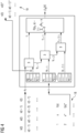
- FIG 2 shows a schematic representation of a method for determining a system model for a technical system.
- An operating data set is shown in the form of a table 11, which is made available in accordance with the first program point 1.
- the operating data set was measured or recorded on the technical system for a specified period of time, for example.
- s(t) denotes the states of the technical system
- a(t) the action specified for the state s(t)
- r(t) the reward achieved for the action a(t) at the state s(t).
- S(t+1) represents the state that arises from the state s(t) after the action a(t).
- the system model 3 is adapted, e.g. by supervised machine learning, until the measured states and the states calculated with the system model 3 match as closely as possible.
- Each action a t can have several action variables x 0 , x 1 , ..., x I-1 .
- the action variables thus represent at least one or more control variables.
- the action a t is now applied to the state s t in a first processing step 13.
- a system model 3 is used for this.
- the next state s t+1 that then arises is determined.
- a reward r t is determined for the transition between the state s t and the state s t+1 .
- the reward r t is passed on to a summation block 14.
- a second processing step 15 the action a t+1 is applied to the state s t+1.
- System model 3 is used again.
- a state s t+2 is determined based on the state s t+1 and the action a t+1 .
- a reward r t-1 is determined for the second processing step 15. The reward r t+1 is fed to the summation block 14.
- the corresponding actions a t+2 to a t+T-1 are carried out with corresponding processing steps and the associated rewards r t+2 to r t+T-1 are determined and forwarded to the summation block 14.
- the system model 3 is used in each case.
- the rewards r t , r t+1 , ..., r t+T-1 are summed up, whereby a weighting factor ⁇ k can preferably be used.
- the sum of the rewards determined in the summation block 14 can be used to optimize the model, i.e. to optimize the actions a t+k for the respective states s t+k . For this purpose, in iterative The individual actions are changed in steps. This optimizes a trajectory.
- the operating data set from the first program point 1 and the system model determined from the second program point 2 on the basis of the operating data set are processed.
- an improved control data set 5 is determined on the basis of the operating data set and the system model using a gradient-free optimization method, in particular using a swarm optimization method.
- a particle swarm optimization method can be used.
- a method for determining a second control data set based on the first control data set using a swarm optimization method is known from WO 2015/043806 A1 Furthermore, a swarm optimization method from " Reinforcement Learning with Particle Swarm Optimization Policy (PSO-P) in Continuous State and Action Spaces" by Daniel Hein et al., Volume 7, Issue 3, July-September 2016, International Journal of Swarm Intelligence Research, pages 23 to 42 .
- PSO-P Reinforcement Learning with Particle Swarm Optimization Policy
- FIG 3 shows a schematic representation of a swarm optimization process.
- a second table 17 is shown with an operational data set that was recorded or measured on the technical system, for example.
- the states s(t) at time t the actions a(t) for the state s(t) at time t, the resulting states s(t+1) at time t+1 and the rewards r(t) are shown.
- the rewards r(t) can also be determined using this process.
- a second processing block 12 is provided with processing steps 13, 15, 16 and with a summation block 14.
- the at FIG 2 determined system model 3 is used to calculate the states and rewards resulting from a measured state and the possible actions.
- a fitness function f st (x) is determined, where an action vector x has the actions a t , a t+1 to a t+T-1 .
- the vector x for the state variables is changed iteratively according to the swarm optimization method until a vector x for the state variables is determined that has a maximum reward sum for the specified number of actions, i.e. a maximum fitness function f st (x).
- the action sequences x are listed in a third table 18 in order with the corresponding fitness function f(x).
- FIG 4 shows the procedure according to FIG 3 , where after determining the best action sequence x according to the third table 18, the state s(t) and the associated action a(t) of the best action sequence are written into a fourth table 19.
- the fifth program point 6 uses a selection procedure to determine, on the basis of the second control data set 5, a specified number of selected parameters that enable better control of the technical system than the specified number of other parameters.
- AMI adaptive mutual information-taking selection method
- the more relevant parameters 7 are then processed either by means of a model-based machine learning method according to the seventh program point 8 or by means of a model-free machine learning method according to the eighth program point 9 in order to determine a control method which is used in the ninth program point 10 to control the technical system.
- a reward function (r t , r t+1 , 7) can represent an optimization criterion such as the lowest possible emission of pollutants in gas turbines or the highest possible power generation in wind turbines.
- optimization criteria such as the lowest possible emission of pollutants in gas turbines or the highest possible power generation in wind turbines.
- other optimization criteria must also be taken into account when determining the reward function.
- the following parameters can be used as classes for a gas turbine, for example: ambient pressure, ambient temperature, gas turbine temperature, exhaust gas temperature, valve positions, etc.
- a wind energy plant i.e. a wind turbine
- the following parameters can be used as classes: rotor speed, power generation output, angle of attack of the rotor blades, rotor orientation, time of day, air pressure, etc.
- FIG 5 shows a schematic representation of a computing unit 20 which is connected via control lines to actuators 22 of a power generation system 21.
- the computing unit 20 is connected via sensor lines to sensors 23.
- the sensors 23 are designed to record parameters, in particular operating parameters and environmental parameters of the power generation system 21.
- the computing unit 20 is designed to control or regulate the power generation system according to the determined control method according to the ninth program point 10.
Landscapes
- Engineering & Computer Science (AREA)
- Artificial Intelligence (AREA)
- Evolutionary Computation (AREA)
- Health & Medical Sciences (AREA)
- Computer Vision & Pattern Recognition (AREA)
- Medical Informatics (AREA)
- Software Systems (AREA)
- Physics & Mathematics (AREA)
- General Physics & Mathematics (AREA)
- Automation & Control Theory (AREA)
- Power Engineering (AREA)
- Feedback Control In General (AREA)
Claims (7)
- Procédé de commande assisté par ordinateur d'un système technique pour obtenir un comportement technique donné à l'avance du système technique,dans lequel on se procure (1) pour la commande du système un ensemble de données de fonctionnement ayant des états du système technique ainsi que les actions déterminées pour les états, qui sont présentes, comme grandeurs de réglage du système technique, en des paramètres de commande,dans lequel on se procure (2) un modèle (3) de système pour la description du mode de fonctionnement du système technique,dans lequel, à l'aide de l'ensemble de l'ensemble de données de fonctionnement et à l'aide du modèle de système, on détermine, au moyen d'une fonction de rétribution par un procédé d'optimisation, un ensemble (5) de données de commande ayant au moins une valeur optimale, pour atteindre un comportement optimum du système technique, du au moins un paramètre de commande pour au moins un état du système,dans lequel, sur la base de l'ensemble de données de commande ayant la au moins une valeur optimale, on sélectionne (6), à l'aide d'un procédé de sélection, un nombre déterminé de paramètres pertinents du système technique, qui rendent possible une commande plus avantageuse du système technique que le nombre déterminé d'autres paramètres du système technique,dans lequel, avec les paramètres plus pertinents sélectionnés et, à l'aide d'un procédé d'apprentissage renforçant soit basé (8) sur un modèle, soit sans modèle (9), on détermine un procédé de commande du système technique,dans lequel on commande (10) le système technique à l'aide du procédé de commande.
- Procédé suivant la revendication 1, dans lequel le procédé de sélection est un procédé de sélection à caractéristique d'information mutuelle adaptatif (AMIFS).
- Procédé suivant l'une des revendications précédentes, dans lequel on détermine le procédé de commande à l'aide d'un procédé d'apprentissage renforçant basé sur un modèle à l'aide du paramètre pertinent sélectionné.
- Procédé suivant l'une des revendications précédentes, dans lequel on utilise un procédé d'optimisation en essaim.
- Procédé suivant la revendication 4, dans lequel on utilise un procédé d'optimisation en essaim de particules comme procédé d'optimisation en essaim.
- Unité informatique, qui est reliée par des lignes de capteur à des capteurs et par des lignes de commande à des actionneurs, et qui est constituée pour exécuter un procédé suivant l'une des revendications précédentes.
- Produit de programme d'ordinateur ayant un code de programme mis en mémoire sur un support, déchiffrable par machine, pour exécuter un procédé suivant l'une des revendications 1 à 5, lors de son exécution.
Priority Applications (4)
| Application Number | Priority Date | Filing Date | Title |
|---|---|---|---|
| EP17203614.7A EP3489773B1 (fr) | 2017-11-24 | 2017-11-24 | Procédé de commande assisté par ordinateur d'un système technique, en particulier d'une installation de production d'énergie |
| US16/766,564 US11720069B2 (en) | 2017-11-24 | 2018-10-11 | Method for the computer-aided control of a technical system, more particularly a power generation installation |
| PCT/EP2018/077663 WO2019101422A1 (fr) | 2017-11-24 | 2018-10-11 | Procédé de commande assistée par ordinateur d'un système technique, en particulier d'une installation de production d'énergie |
| CN201880075694.1A CN111356959B (zh) | 2017-11-24 | 2018-10-11 | 用于计算机辅助地控制技术系统的方法 |
Applications Claiming Priority (1)
| Application Number | Priority Date | Filing Date | Title |
|---|---|---|---|
| EP17203614.7A EP3489773B1 (fr) | 2017-11-24 | 2017-11-24 | Procédé de commande assisté par ordinateur d'un système technique, en particulier d'une installation de production d'énergie |
Publications (3)
| Publication Number | Publication Date |
|---|---|
| EP3489773A1 EP3489773A1 (fr) | 2019-05-29 |
| EP3489773C0 EP3489773C0 (fr) | 2024-12-25 |
| EP3489773B1 true EP3489773B1 (fr) | 2024-12-25 |
Family
ID=60543355
Family Applications (1)
| Application Number | Title | Priority Date | Filing Date |
|---|---|---|---|
| EP17203614.7A Active EP3489773B1 (fr) | 2017-11-24 | 2017-11-24 | Procédé de commande assisté par ordinateur d'un système technique, en particulier d'une installation de production d'énergie |
Country Status (4)
| Country | Link |
|---|---|
| US (1) | US11720069B2 (fr) |
| EP (1) | EP3489773B1 (fr) |
| CN (1) | CN111356959B (fr) |
| WO (1) | WO2019101422A1 (fr) |
Families Citing this family (1)
| Publication number | Priority date | Publication date | Assignee | Title |
|---|---|---|---|---|
| DE102021210393A1 (de) | 2021-09-20 | 2023-03-23 | Robert Bosch Gesellschaft mit beschränkter Haftung | Verfahren und Vorrichtung zum Betreiben eines technischen Systems |
Family Cites Families (12)
| Publication number | Priority date | Publication date | Assignee | Title |
|---|---|---|---|---|
| US20050192680A1 (en) * | 2004-02-27 | 2005-09-01 | Mark Cascia | System and method for optimizing global set points in a building environmental management system |
| DE102007001024B4 (de) | 2007-01-02 | 2008-10-02 | Siemens Ag | Verfahren zur rechnergestützten Regelung und/oder Steuerung eines technischen Systems insbesondere einer Gasturbine |
| EP2246755A1 (fr) * | 2009-04-22 | 2010-11-03 | Powitec Intelligent Technologies GmbH | Circuit de commande |
| EP2296062B1 (fr) * | 2009-09-09 | 2021-06-23 | Siemens Aktiengesellschaft | Procédé d'apprentissage assisté par ordinateur d'une commande et/ou d'un réglage d'un système technique |
| JP5832644B2 (ja) * | 2011-06-03 | 2015-12-16 | シーメンス アクチエンゲゼルシヤフトSiemens Aktiengesellschaft | 殊にガスタービンまたは風力タービンのような技術システムのデータドリブンモデルを計算機支援で形成する方法 |
| CN105556401B (zh) | 2013-09-25 | 2019-02-22 | 西门子公司 | 用于计算机辅助地控制和/或调节技术系统的方法 |
| DE102014212747A1 (de) * | 2014-07-01 | 2016-01-07 | Siemens Aktiengesellschaft | Interaktives Assistenzsystem und Verfahren zur rechnergestützten Steuerungsoptimierung für ein technisches System |
| US9897984B2 (en) * | 2014-08-05 | 2018-02-20 | Mitsubishi Electric Research Laboratories, Inc. | Model predictive control with uncertainties |
| CN104598654A (zh) * | 2014-10-07 | 2015-05-06 | 芜湖扬宇机电技术开发有限公司 | 点火提前角预测系统及其方法 |
| US20160209031A1 (en) * | 2015-01-20 | 2016-07-21 | Alstom Technology Ltd | Model-based controls for a furnace and method for controlling the furnace |
| CN106485594A (zh) | 2016-05-10 | 2017-03-08 | 国网江苏省电力公司南京供电公司 | 一种主配网一体化事故响应决策方法 |
| DE102016010796A1 (de) * | 2016-09-09 | 2017-03-30 | Daimler Ag | Verfahren zur Kalibrierung eines Simulationsmodells zur Berechnung der Funktionalität einer Abgasnachbehandlungseinrichtung |
-
2017
- 2017-11-24 EP EP17203614.7A patent/EP3489773B1/fr active Active
-
2018
- 2018-10-11 US US16/766,564 patent/US11720069B2/en active Active
- 2018-10-11 WO PCT/EP2018/077663 patent/WO2019101422A1/fr not_active Ceased
- 2018-10-11 CN CN201880075694.1A patent/CN111356959B/zh active Active
Also Published As
| Publication number | Publication date |
|---|---|
| US20200348631A1 (en) | 2020-11-05 |
| CN111356959B (zh) | 2024-05-28 |
| CN111356959A (zh) | 2020-06-30 |
| EP3489773A1 (fr) | 2019-05-29 |
| EP3489773C0 (fr) | 2024-12-25 |
| WO2019101422A1 (fr) | 2019-05-31 |
| US11720069B2 (en) | 2023-08-08 |
Similar Documents
| Publication | Publication Date | Title |
|---|---|---|
| EP2112568B1 (fr) | Procédé de commande et/ou réglage assistées par ordinateur d'un système technique | |
| EP2108139B1 (fr) | Procédé de régulation et/ou de contrôle assisté par ordinateur d'un système technique, en particulier d'une turbine à gaz | |
| EP2106576B1 (fr) | Procédé de commande et/ou de régulation d'un système technique assistées par ordinateur | |
| EP2697695B1 (fr) | Procédé pour générer, de manière assistée par ordinateur, un modèle piloté par des données d'un système technique, notamment d'une turbine à gaz ou d'une éolienne | |
| EP3132317B1 (fr) | Procédé permettant l'optimisation assistée par ordinateur de la commande d'une installation au moyen d'un module de simulation | |
| DE102019126310A1 (de) | System und Verfahren zum Optimieren der Verbrennung eines Kessels | |
| EP2880499B1 (fr) | Procédé de commande et/ou de régulation assistée par ordinateur d'un système technique | |
| WO2014121863A1 (fr) | Procédé et dispositif de commande d'une installation de production d'énergie exploitable avec une source d'énergie renouvelable | |
| EP3022611B1 (fr) | Procédé de commande et/ou de régulation assistée(s) par ordinateur d'un système technique | |
| WO2020187591A1 (fr) | Procédé et dispositif de commande d'un robot | |
| EP4235317B1 (fr) | Procédé de commande d'une machine par un agent de commande basé sur l'apprentissage, ainsi que dispositif de commande | |
| DE102019126293B4 (de) | System und Verfahren zum Regeln des Betriebs eines Kessels | |
| EP2943841B1 (fr) | Procédé de commande et/ou de régulation, assistée par ordinateur, d'un système technique | |
| EP4375768B1 (fr) | Procédé et commande de machine pour commander une machine | |
| WO2023072528A1 (fr) | Procédé et dispositif de commande pour commander un système technique | |
| DE102011075337A1 (de) | Verfahren und Vorrichtung zur Ansteuerung einer Anlage | |
| EP3489773A1 (fr) | Procédé de commande assisté par ordinateur d'un système technique, en particulier d'une installation de production d'énergie | |
| WO2024002823A1 (fr) | Dispositif de commande de machine et procédé de configuration du dispositif de commande de machine | |
| EP4273636A1 (fr) | Procédé et dispositif de commande permettant de commander une machine | |
| DE102011076969B4 (de) | Verfahren zum rechnergestützten Lernen einer Regelung und/oder Steuerung eines technischen Systems | |
| WO2025168305A1 (fr) | Commande d'une machine à l'aide d'un dispositif de commande basé sur l'apprentissage | |
| WO2025168288A1 (fr) | Commande de machine au moyen d'un dispositif de commande basé sur l'apprentissage | |
| WO2020057940A1 (fr) | Procédé informatisé destiné à estimer un comportement technique d'un dispositif |
Legal Events
| Date | Code | Title | Description |
|---|---|---|---|
| PUAI | Public reference made under article 153(3) epc to a published international application that has entered the european phase |
Free format text: ORIGINAL CODE: 0009012 |
|
| STAA | Information on the status of an ep patent application or granted ep patent |
Free format text: STATUS: THE APPLICATION HAS BEEN PUBLISHED |
|
| AK | Designated contracting states |
Kind code of ref document: A1 Designated state(s): AL AT BE BG CH CY CZ DE DK EE ES FI FR GB GR HR HU IE IS IT LI LT LU LV MC MK MT NL NO PL PT RO RS SE SI SK SM TR |
|
| AX | Request for extension of the european patent |
Extension state: BA ME |
|
| STAA | Information on the status of an ep patent application or granted ep patent |
Free format text: STATUS: REQUEST FOR EXAMINATION WAS MADE |
|
| 17P | Request for examination filed |
Effective date: 20190617 |
|
| RBV | Designated contracting states (corrected) |
Designated state(s): AL AT BE BG CH CY CZ DE DK EE ES FI FR GB GR HR HU IE IS IT LI LT LU LV MC MK MT NL NO PL PT RO RS SE SI SK SM TR |
|
| STAA | Information on the status of an ep patent application or granted ep patent |
Free format text: STATUS: EXAMINATION IS IN PROGRESS |
|
| 17Q | First examination report despatched |
Effective date: 20200515 |
|
| GRAP | Despatch of communication of intention to grant a patent |
Free format text: ORIGINAL CODE: EPIDOSNIGR1 |
|
| STAA | Information on the status of an ep patent application or granted ep patent |
Free format text: STATUS: GRANT OF PATENT IS INTENDED |
|
| INTG | Intention to grant announced |
Effective date: 20240814 |
|
| GRAS | Grant fee paid |
Free format text: ORIGINAL CODE: EPIDOSNIGR3 |
|
| GRAA | (expected) grant |
Free format text: ORIGINAL CODE: 0009210 |
|
| STAA | Information on the status of an ep patent application or granted ep patent |
Free format text: STATUS: THE PATENT HAS BEEN GRANTED |
|
| AK | Designated contracting states |
Kind code of ref document: B1 Designated state(s): AL AT BE BG CH CY CZ DE DK EE ES FI FR GB GR HR HU IE IS IT LI LT LU LV MC MK MT NL NO PL PT RO RS SE SI SK SM TR |
|
| REG | Reference to a national code |
Ref country code: GB Ref legal event code: FG4D Free format text: NOT ENGLISH |
|
| REG | Reference to a national code |
Ref country code: CH Ref legal event code: EP |
|
| REG | Reference to a national code |
Ref country code: DE Ref legal event code: R096 Ref document number: 502017016623 Country of ref document: DE |
|
| REG | Reference to a national code |
Ref country code: IE Ref legal event code: FG4D Free format text: LANGUAGE OF EP DOCUMENT: GERMAN |
|
| U01 | Request for unitary effect filed |
Effective date: 20241225 |
|
| U07 | Unitary effect registered |
Designated state(s): AT BE BG DE DK EE FI FR IT LT LU LV MT NL PT RO SE SI Effective date: 20250108 |
|
| PG25 | Lapsed in a contracting state [announced via postgrant information from national office to epo] |
Ref country code: HR Free format text: LAPSE BECAUSE OF FAILURE TO SUBMIT A TRANSLATION OF THE DESCRIPTION OR TO PAY THE FEE WITHIN THE PRESCRIBED TIME-LIMIT Effective date: 20241225 |
|
| PG25 | Lapsed in a contracting state [announced via postgrant information from national office to epo] |
Ref country code: NO Free format text: LAPSE BECAUSE OF FAILURE TO SUBMIT A TRANSLATION OF THE DESCRIPTION OR TO PAY THE FEE WITHIN THE PRESCRIBED TIME-LIMIT Effective date: 20250325 |
|
| PG25 | Lapsed in a contracting state [announced via postgrant information from national office to epo] |
Ref country code: GR Free format text: LAPSE BECAUSE OF FAILURE TO SUBMIT A TRANSLATION OF THE DESCRIPTION OR TO PAY THE FEE WITHIN THE PRESCRIBED TIME-LIMIT Effective date: 20250326 |
|
| PG25 | Lapsed in a contracting state [announced via postgrant information from national office to epo] |
Ref country code: RS Free format text: LAPSE BECAUSE OF FAILURE TO SUBMIT A TRANSLATION OF THE DESCRIPTION OR TO PAY THE FEE WITHIN THE PRESCRIBED TIME-LIMIT Effective date: 20250325 |
|
| PG25 | Lapsed in a contracting state [announced via postgrant information from national office to epo] |
Ref country code: SM Free format text: LAPSE BECAUSE OF FAILURE TO SUBMIT A TRANSLATION OF THE DESCRIPTION OR TO PAY THE FEE WITHIN THE PRESCRIBED TIME-LIMIT Effective date: 20241225 |
|
| PG25 | Lapsed in a contracting state [announced via postgrant information from national office to epo] |
Ref country code: PL Free format text: LAPSE BECAUSE OF FAILURE TO SUBMIT A TRANSLATION OF THE DESCRIPTION OR TO PAY THE FEE WITHIN THE PRESCRIBED TIME-LIMIT Effective date: 20241225 |
|
| PG25 | Lapsed in a contracting state [announced via postgrant information from national office to epo] |
Ref country code: ES Free format text: LAPSE BECAUSE OF FAILURE TO SUBMIT A TRANSLATION OF THE DESCRIPTION OR TO PAY THE FEE WITHIN THE PRESCRIBED TIME-LIMIT Effective date: 20241225 |
|
| PG25 | Lapsed in a contracting state [announced via postgrant information from national office to epo] |
Ref country code: IS Free format text: LAPSE BECAUSE OF FAILURE TO SUBMIT A TRANSLATION OF THE DESCRIPTION OR TO PAY THE FEE WITHIN THE PRESCRIBED TIME-LIMIT Effective date: 20250425 |
|
| PG25 | Lapsed in a contracting state [announced via postgrant information from national office to epo] |
Ref country code: SK Free format text: LAPSE BECAUSE OF FAILURE TO SUBMIT A TRANSLATION OF THE DESCRIPTION OR TO PAY THE FEE WITHIN THE PRESCRIBED TIME-LIMIT Effective date: 20241225 |
|
| PG25 | Lapsed in a contracting state [announced via postgrant information from national office to epo] |
Ref country code: CZ Free format text: LAPSE BECAUSE OF FAILURE TO SUBMIT A TRANSLATION OF THE DESCRIPTION OR TO PAY THE FEE WITHIN THE PRESCRIBED TIME-LIMIT Effective date: 20241225 |
|
| PLBE | No opposition filed within time limit |
Free format text: ORIGINAL CODE: 0009261 |
|
| STAA | Information on the status of an ep patent application or granted ep patent |
Free format text: STATUS: NO OPPOSITION FILED WITHIN TIME LIMIT |
|
| 26N | No opposition filed |
Effective date: 20250926 |
|
| U20 | Renewal fee for the european patent with unitary effect paid |
Year of fee payment: 9 Effective date: 20251120 |