EP3490129A1 - Circuit protection électronique - Google Patents
Circuit protection électronique Download PDFInfo
- Publication number
- EP3490129A1 EP3490129A1 EP17203987.7A EP17203987A EP3490129A1 EP 3490129 A1 EP3490129 A1 EP 3490129A1 EP 17203987 A EP17203987 A EP 17203987A EP 3490129 A1 EP3490129 A1 EP 3490129A1
- Authority
- EP
- European Patent Office
- Prior art keywords
- circuit
- intermediate circuit
- link capacitor
- link
- voltage
- Prior art date
- Legal status (The legal status is an assumption and is not a legal conclusion. Google has not performed a legal analysis and makes no representation as to the accuracy of the status listed.)
- Granted
Links
Images

Classifications
-
- H—ELECTRICITY
- H02—GENERATION; CONVERSION OR DISTRIBUTION OF ELECTRIC POWER
- H02M—APPARATUS FOR CONVERSION BETWEEN AC AND AC, BETWEEN AC AND DC, OR BETWEEN DC AND DC, AND FOR USE WITH MAINS OR SIMILAR POWER SUPPLY SYSTEMS; CONVERSION OF DC OR AC INPUT POWER INTO SURGE OUTPUT POWER; CONTROL OR REGULATION THEREOF
- H02M5/00—Conversion of AC power input into AC power output, e.g. for change of voltage, for change of frequency, for change of number of phases
- H02M5/02—Conversion of AC power input into AC power output, e.g. for change of voltage, for change of frequency, for change of number of phases without intermediate conversion into DC
- H02M5/04—Conversion of AC power input into AC power output, e.g. for change of voltage, for change of frequency, for change of number of phases without intermediate conversion into DC by static converters
- H02M5/10—Conversion of AC power input into AC power output, e.g. for change of voltage, for change of frequency, for change of number of phases without intermediate conversion into DC by static converters using transformers
- H02M5/16—Conversion of AC power input into AC power output, e.g. for change of voltage, for change of frequency, for change of number of phases without intermediate conversion into DC by static converters using transformers for conversion of frequency
-
- H—ELECTRICITY
- H02—GENERATION; CONVERSION OR DISTRIBUTION OF ELECTRIC POWER
- H02M—APPARATUS FOR CONVERSION BETWEEN AC AND AC, BETWEEN AC AND DC, OR BETWEEN DC AND DC, AND FOR USE WITH MAINS OR SIMILAR POWER SUPPLY SYSTEMS; CONVERSION OF DC OR AC INPUT POWER INTO SURGE OUTPUT POWER; CONTROL OR REGULATION THEREOF
- H02M1/00—Details of apparatus for conversion
- H02M1/32—Means for protecting converters other than automatic disconnection
-
- H—ELECTRICITY
- H02—GENERATION; CONVERSION OR DISTRIBUTION OF ELECTRIC POWER
- H02H—EMERGENCY PROTECTIVE CIRCUIT ARRANGEMENTS
- H02H7/00—Emergency protective circuit arrangements specially adapted for specific types of electric machines or apparatus or for sectionalised protection of cable or line systems, and effecting automatic switching in the event of an undesired change from normal working conditions
- H02H7/10—Emergency protective circuit arrangements specially adapted for specific types of electric machines or apparatus or for sectionalised protection of cable or line systems, and effecting automatic switching in the event of an undesired change from normal working conditions for converters; for rectifiers
- H02H7/12—Emergency protective circuit arrangements specially adapted for specific types of electric machines or apparatus or for sectionalised protection of cable or line systems, and effecting automatic switching in the event of an undesired change from normal working conditions for converters; for rectifiers for static converters or rectifiers
- H02H7/1216—Emergency protective circuit arrangements specially adapted for specific types of electric machines or apparatus or for sectionalised protection of cable or line systems, and effecting automatic switching in the event of an undesired change from normal working conditions for converters; for rectifiers for static converters or rectifiers for AC-AC converters
-
- H—ELECTRICITY
- H02—GENERATION; CONVERSION OR DISTRIBUTION OF ELECTRIC POWER
- H02H—EMERGENCY PROTECTIVE CIRCUIT ARRANGEMENTS
- H02H7/00—Emergency protective circuit arrangements specially adapted for specific types of electric machines or apparatus or for sectionalised protection of cable or line systems, and effecting automatic switching in the event of an undesired change from normal working conditions
- H02H7/16—Emergency protective circuit arrangements specially adapted for specific types of electric machines or apparatus or for sectionalised protection of cable or line systems, and effecting automatic switching in the event of an undesired change from normal working conditions for capacitors
-
- H—ELECTRICITY
- H02—GENERATION; CONVERSION OR DISTRIBUTION OF ELECTRIC POWER
- H02H—EMERGENCY PROTECTIVE CIRCUIT ARRANGEMENTS
- H02H9/00—Emergency protective circuit arrangements for limiting excess current or voltage without disconnection
- H02H9/001—Emergency protective circuit arrangements for limiting excess current or voltage without disconnection limiting speed of change of electric quantities, e.g. soft switching on or off
- H02H9/002—Emergency protective circuit arrangements for limiting excess current or voltage without disconnection limiting speed of change of electric quantities, e.g. soft switching on or off limiting inrush current on switching on of inductive loads subjected to remanence, e.g. transformers
-
- H—ELECTRICITY
- H02—GENERATION; CONVERSION OR DISTRIBUTION OF ELECTRIC POWER
- H02M—APPARATUS FOR CONVERSION BETWEEN AC AND AC, BETWEEN AC AND DC, OR BETWEEN DC AND DC, AND FOR USE WITH MAINS OR SIMILAR POWER SUPPLY SYSTEMS; CONVERSION OF DC OR AC INPUT POWER INTO SURGE OUTPUT POWER; CONTROL OR REGULATION THEREOF
- H02M1/00—Details of apparatus for conversion
- H02M1/36—Means for starting or stopping converters
-
- H—ELECTRICITY
- H02—GENERATION; CONVERSION OR DISTRIBUTION OF ELECTRIC POWER
- H02M—APPARATUS FOR CONVERSION BETWEEN AC AND AC, BETWEEN AC AND DC, OR BETWEEN DC AND DC, AND FOR USE WITH MAINS OR SIMILAR POWER SUPPLY SYSTEMS; CONVERSION OF DC OR AC INPUT POWER INTO SURGE OUTPUT POWER; CONTROL OR REGULATION THEREOF
- H02M3/00—Conversion of DC power input into DC power output
- H02M3/02—Conversion of DC power input into DC power output without intermediate conversion into AC
- H02M3/04—Conversion of DC power input into DC power output without intermediate conversion into AC by static converters
- H02M3/06—Conversion of DC power input into DC power output without intermediate conversion into AC by static converters using resistors or capacitors, e.g. potential divider
- H02M3/07—Conversion of DC power input into DC power output without intermediate conversion into AC by static converters using resistors or capacitors, e.g. potential divider using capacitors charged and discharged alternately by semiconductor devices with control electrode, e.g. charge pumps
-
- H—ELECTRICITY
- H02—GENERATION; CONVERSION OR DISTRIBUTION OF ELECTRIC POWER
- H02M—APPARATUS FOR CONVERSION BETWEEN AC AND AC, BETWEEN AC AND DC, OR BETWEEN DC AND DC, AND FOR USE WITH MAINS OR SIMILAR POWER SUPPLY SYSTEMS; CONVERSION OF DC OR AC INPUT POWER INTO SURGE OUTPUT POWER; CONTROL OR REGULATION THEREOF
- H02M7/00—Conversion of AC power input into DC power output; Conversion of DC power input into AC power output
- H02M7/02—Conversion of AC power input into DC power output without possibility of reversal
- H02M7/04—Conversion of AC power input into DC power output without possibility of reversal by static converters
- H02M7/06—Conversion of AC power input into DC power output without possibility of reversal by static converters using discharge tubes without control electrode or semiconductor devices without control electrode
- H02M7/062—Avoiding or suppressing excessive transient voltages or currents
Definitions
- the invention relates to an electronic protection circuit for one of two series-connected DC link capacitor units of a DC link. Furthermore, the invention relates to a frequency converter for operating an electrical machine, with a rectifier and an inverter, which are interconnected via an intermediate circuit, wherein the intermediate circuit, although having series-connected intermediate circuit capacitor units.
- Frequency inverters typically have a rectifier and an inverter, which are interconnected by means of a DC link.
- the intermediate circuit has two DC link capacitor units connected in series. In this case, several DC link capacitors connected in series and / or in parallel can be provided per DC link capacitor unit.
- electrolytic capacitors are suitable as DC link capacitors.
- Electrolytic capacitors are poled capacitors whose anode electrode consists of a metal such as aluminum, tantalum or niobium, on which an extremely thin, electrically insulating layer is applied as a dielectric.
- the cathode electrode is formed by the electrolyte, which is formed either in liquid form as an ion conductor or in solid form as an electron conductor.
- Electrolytic capacitors are located in almost every electrical circuit. Electrolytic capacitors have the great advantage over other capacitor technologies of achieving high capacitance values in small package sizes. Therefore, they are used especially in applications where energy is to be cached in a small space. A possible application for one Electrolytic capacitor is used as a smoothing capacitor in a rectifier circuit. Since the dielectric strength of electrolytic capacitors is limited, in 400 V applications, several electrolytic capacitors are connected in series in order to achieve the necessary dielectric strength. Such an embodiment can be found, for example, in the intermediate circuit of 400 V frequency converters.
- electrolytic capacitors are used here as smoothing capacitors, which are connected downstream of a mains voltage rectifier circuit.
- the power from the supply network in the capacitors is set solely by the impedances of the supply network and the rectifier circuit, Since these impedances are usually very low, very high currents can occur, which can lead to dangerous bursting of the electrolytic capacitors.
- Another protective measure is the use of quick fuses, which must be connected upstream of the device, for example the frequency inverter. These fuses very quickly prevent the flow of electricity and energy into the device in the event of a fault. As a result, the severity of bursting of an electrolytic capacitor is significantly reduced. However, these fuses are comparatively expensive compared to other types of backups.
- an electronic circuit for short-circuit monitoring of one of at least two series-connected DC link capacitor units is known.
- a reference voltage derived from the intermediate circuit voltage is used as the control signal, which generates an error signal in the event of a capacitor short circuit.
- the reference voltage is formed by a chain of resistors connected in series, which is connected in parallel with the intermediate circuit capacitors to be monitored.
- an electronic protection circuit for one of two series-connected DC link capacitor units of an intermediate circuits, with a per DC link capacitor unit provided and connected in parallel to this symmetry resistor for voltage balancing to the DC link capacitor units, each provided with a DC link capacitor unit for detecting the voltage applied to this intermediate circuit capacitor unit, with a comparison device which compares the voltages applied to the intermediate circuit capacitor units with one another and outputs a corresponding control signal in the event of voltage asymmetry, and with a disconnection device which, upon detection, emits one of the comparator devices Control signal interrupts the flow of current in the DC link.
- the protection circuit according to the invention ensures that there is an immediate interruption of the current flow in the intermediate circuit in the event of a short circuit. Bursting of the affected DC link capacitor unit is thus prevented, whereby an effective personal and property protection is realized.
- the protective circuit according to the invention basically consists of two components.
- a voltage measurement is performed on the DC link capacitor units. If one of the two DC link capacitor units fails because of a short circuit, then the voltage applied to the non-defective voltage, that is to say the other capacitor unit, increases, which is recognized as an overvoltage case.
- the second circuit component serves to prevent the flow of current and energy into the DC link capacitor. This prevents the DC link from being energized until the DC link capacitor unit, which has not yet broken, bursts.
- a comparison device For the purpose of detecting an overload case, a comparison device is provided which compares the voltages applied to the intermediate circuit capacitor units with each other. For each DC link capacitor unit, a symmetry resistor connected in parallel with this DC link capacitor unit is provided which serves for voltage balancing on the DC link capacitor units. If a voltage asymmetry is now detected by means of the comparison device, this means that an excessively high voltage is applied to one of the two DC link capacitor units. Therefore, the comparator emits a corresponding control signal, which serves as a signal for interrupting the current interruption.
- a unit for detecting the voltage applied to this intermediate circuit capacitor unit is provided per DC link capacitor unit.
- the signals emitted by these detection units are compared by the comparison device.
- the two DC link capacitor units are in tact.
- the failure of one of the two units leads to an immediate voltage asymmetry, which by means of Comparative device is detected by voltage comparison.
- the protective circuit When the voltage asymmetry is detected, an interruption of the current flow into the DC link takes place by means of the protective circuit according to the invention.
- the shutdown of the protection circuit which is in communication with the comparison device connection.
- the shutdown device prevents the current and energy flow in the intermediate circuit and thus also in the still intact DC link capacitor unit, which is thus protected from accidental bursting due to overvoltage.
- an easy to implement protection circuit is thus provided, which effectively serves a personal and property protection, since it interrupts an instantaneous current flow in the event of an overvoltage, which effectively prevents a DC link capacitor unit from bursting.
- an intermediate circuit capacitor unit can be formed from a plurality of electrolytic capacitors, which are connected in parallel and / or in series.
- the invention furthermore proposes a method for disconnecting an intermediate circuit in the event of a short circuit of one of two DC link capacitor units connected in series, in which voltage balancing takes place on the DC link capacitors, in which case the voltage applied to the DC link capacitor units is detected, in which case the DC link capacitor units applied voltages are compared with each other, and in which in the presence of a detected by the comparator voltage asymmetry of the current flow is interrupted in the intermediate circuit.
- the method according to the invention provides the advantages already explained above with reference to the protective circuit according to the invention.
- a unit for voltage detection has an optocoupler connected in series with the symmetry resistance of the associated intermediate circuit capacitor unit is switched. Accordingly, it is thus provided that an optocoupler is connected in the symmetry circuit per DC link capacitor unit, specifically in series with the balancing resistor of the respectively associated DC link capacitor unit.
- the shutdown device of the protection circuit comprises, according to a further feature of the invention, a rectifier and a precharge circuit for the intermediate circuit.
- the rectifier is connected upstream of the DC link and preferably has thyristors as a rectifier semiconductor.
- the precharge circuit is connected in parallel with the thyristor at phase L1 and has a diode and a temperature-dependent resistor connected in series therewith.
- the thyristors of the rectifier are controlled in this case to allow the flow of energy through the rectifier circuit in the DC link.
- the Vorladezweig the Vorladescrien is connected.
- the diode and the resistance of the precharge circuit connected in series with it take over the voltage precharge of the intermediate circuit. If the voltage level in the DC link is sufficient, the thyristors are switched on. It is the purpose of the precharge circuit to prevent larger currents in the supply network when switching.
- the thyristors of the rectifier belonging to the shutdown device are switched off.
- the shutdown device has for this purpose via a thyristor, that is means for deactivating a thyristors driving signal.
- a thyristor that is means for deactivating a thyristors driving signal.
- the resistance of the precharge circuit is a temperature-dependent resistor, which becomes high-impedance with increasing current flow, which is the case in the above-described fault of the short circuit of a DC link capacitor unit.
- the Temperature-dependent resistance of the precharge circuit is therefore designed so that a Stromhneunteritati takes place in the DC link before it can come to an explosive bursting one of the DC link capacitor units.
- the above shutdown device uses the already provided for a proper summation of the intermediate circuit precharge circuit to accomplish in the event of a fault, that is, in the case of a short circuit of a DC link capacitor unit immediate separation of the DC link from the supply network.
- the Vorladescnies in case of error, a protective function.
- the temperature-dependent resistance of the precharge circuit in the high-impedance state prevents a renewed, unintentional switching on in the event of an existing fault, which provides additional security for the user.
- a method is also proposed in this connection, in which the current flows via thyristors into the intermediate circuit, the current flow in the intermediate circuit being blocked by blocking the thyristors. It is also proposed that the current flow in blocked thyristors via a pre-charge circuit with a temperature-dependent resistor in the intermediate circuit, wherein the current flow is prevented in the intermediate circuit as a result of Hochohmig becoming the temperature-dependent resistor.
- the invention further proposes a frequency converter for operating an electrical machine, comprising a rectifier and an inverter, which are interconnected via an intermediate circuit, wherein the intermediate circuit has two series-connected intermediate circuit capacitor units , wherein such a frequency converter is characterized by an electrical safety circuit, as described above.
- the protection circuit according to the invention is particularly suitable for use in a frequency converter.
- the already provided rectifier of the frequency converter and the likewise already provided pre-charge circuit of the frequency converter can be used as circuit components of the inventive shutdown device.
- the circuit provided according to the invention provides in the event of a fault, that is, in particular in the event of a short circuit of a DC link capacitor unit an immediate separation of the DC link from the supply network safely. An explosive bursting of a DC link capacitor unit can be effectively prevented.
- the protection circuit according to the invention is not only suitable for use in frequency converters. Further application examples are the use in regenerative units, in active harmonic filters, in UPS systems, in an Active Front End or in an Active Infeed Converter.
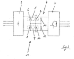
- FIG. 3 lets you recognize a frequency converter 1 in a block diagram. This is used to operate an electric machine, not shown in detail in the figures, for example, a motor, and has in a conventional manner via a rectifier 2 and an inverter 3. In this case, the rectifier 2 and the inverter 3 are interconnected via an intermediate circuit 4.
- the frequency converter 1 is connected on the input side to the phases L1, L2 and L3 of a supply network.
- the intermediate circuit 4 of the frequency converter 1 has two DC link capacitor units 5 and 8, which are connected in series.
- each intermediate circuit capacitor unit 5 or 8 has two capacitors 6 and 7 or 9 and 10 connected in parallel.
- two capacitor paths are provided, the capacitors 6 and 9 and the capacitors 7 and 10 being connected in series.
- the capacitors 6, 7, 9 and 10 are in each case electrolytic capacitors which can explode in the event of an overvoltage. Such a bursting is prevented with the protection circuit 13 according to the invention, as can be deduced from the further description, in particular with reference to FIGS Figures 1 and 2 results.
- the protection circuit 13 has per DC link capacitor unit 5 or 8 via a balancing resistor 11 or 12, which is connected in parallel to the associated DC link capacitor unit 5 and 8 respectively. Accordingly, the intermediate circuit capacitor unit 5 of the symmetry resistor 11 and the DC link capacitor unit 8 of the symmetry resistor 12 is assigned, as shown in particular the illustration FIG. 1 lets recognize.
- the symmetry resistors 11 and 12 serve to balance the voltage at the DC link capacitor units 5 and 8.
- each detection unit 14 or 15 has an optocoupler 16 or 17 and a resistor 18 or 19, which are respectively connected in series with the balancing resistor 11 or 12 of the associated intermediate circuit capacitor unit 5 and 8 respectively.
- the DC link capacitor unit 5 is associated with the detection unit 14, which is connected in series with the balancing resistor 11.
- the detection unit 15 is assigned to the DC link capacitor unit 8 and accordingly connected in series with the balancing resistor 12. This factual relationship also arises FIG. 1 ,
- the voltage applied to the DC link capacitor units 5 and 8 voltages are compared with each other in the operating case, the comparator 31 in the event of a detected voltage asymmetry by means of a signal processing 21 generates a control signal corresponding to the arrow 23rd a shutdown device for immediate interruption of the current flow in the intermediate circuit 4 is activated.
- the above-described circuit components are realized in the embodiment shown circuit technology on a common board 22.
- the shutdown device 20 is described in detail in FIG. 2 shown. This includes the previously described rectifier 2, a thyristor drive 32 and a precharge circuit 24.
- the rectifier 2 has three thyristors 25, 26 and 27, which are connected to the phases of the supply network.
- a first thyristor 25 of the phase L1 a second thyristor 26 of the phase L2 and a third thyristor 27 of the phase L3 assigned.
- the thyristors 25, 26 and 27 are each part of a thyristor 33, 34 and 35, which may also have other components, in particular diodes.
- the precharge circuit 24 is connected in parallel to the first thyristor 25 to phase L1 of the supply network.
- the precharge circuit consists of a series circuit of a diode 29 and a temperature-dependent resistor 30, which becomes high-impedance at high temperatures.
- a plurality of resistors connected in series and / or in parallel.
- the operation of the protection circuit 13 according to the invention is the following:
- the thyristors 25, 26 and 27 are controlled via the thyristor 32, which allows an energy, that is to say current flow from the supply network via the rectifier 2 into the intermediate circuit 4.
- the diode 29 and the resistor 30 of the precharge circuit 24 have a negligible effect, since the precharge circuit 24 is connected in parallel with the first thyristor 25.
- a Parallel connection to the second thyristor 26 or the third thyristor 27 may be provided.
- the precharging circuit 24 takes over the voltage precharging of the intermediate circuit 4. Only when the voltage level in the intermediate circuit 4 is sufficient are the thyristors 25, 26 and 27 switched on by means of the thyristor control 32. Such a summons prevents large currents in the supply network when the frequency converter 1 is switched on.
- the voltages applied to the intermediate circuit capacitor units 5 and 8 during normal operation are detected by means of the associated detection unit in FIGS. 14 and 15.
- a current flows through the diodes of the optocouplers 16 and 17, which causes switching, that is, switching on or off the associated optocoupler outputs.
- Via the signal processing 21 of the comparison device 31 a superordinate control is informed so that the voltages at the intermediate circuit capacitor units 5 and 8 are in the specified range.
- the signal transmission to the shutdown device 20 causes a shutdown of the thyristors 25, 26 and 27 via the thyristor drive 32.
- a current flow via the precharge branch 28 of the precharge circuit 24, and thus set via the diode 29 and the resistor 30 will. Since the resistor 30 is a PTC element, this is high impedance at high current flow, which is given large current flow in case of failure of a short circuit of a DC link capacitor unit.
- the intermediate circuit 4 is disconnected from the supply network. Thus, no energy flow takes place, neither via the thyristors 25, 26 and 27, nor via the precharge circuit 24 in the intermediate circuit 4.
- the DC link capacitor units 5 and 8 are protected from further destruction.
- the too high voltage causes sparking at the weakest points of the anode foil and an increased leakage current in the capacitor. This results in more power loss in the condenser and it comes to gas formation inside. This results in a temperature increase inside the electrolytic capacitor. As a result of such an increase in temperature, the breakdown field strength of the electrolyte decreases, which causes sparking in the entire capacitor winding. This sparking results in increased gas formation, resulting in an increase in pressure inside the condenser. As a result, the combination of sparking, temperature increase, gas formation and increased pressure result in explosive bursting of the capacitor.
- Previously known electrolytic capacitors typically have a valve that provides a way to dissipate outwardly generated gas to the outside to reduce mechanical pressure. This valve is in case of fault of the short circuit of a capacitor ineffective, since it is too slow. Because previously known valves are designed to discharge emerging gas in case of overload, and not in the event of a short circuit. Thus, an overload can last for several minutes before the electrolytic capacitor is destroyed or triggers the valve. In the event of a short circuit, a capacitor is destroyed after just a few milliseconds, so that valve tripping is not an effective protection mechanism in the event of a short circuit.
- the protection circuit according to the invention has a response time of 3 ms to 15 ms, preferably from 4 ms to 12 ms, more preferably from 5 ms to 10 ms, for example from about 6 ms, that is, the time between the occurrence of a short circuit at one of two DC link capacitor units 5 and 8 and the suppression of a current flow in the intermediate circuit 4 is about 6 ms.
Landscapes
- Engineering & Computer Science (AREA)
- Power Engineering (AREA)
- Protection Of Static Devices (AREA)
- Rectifiers (AREA)
Priority Applications (3)
| Application Number | Priority Date | Filing Date | Title |
|---|---|---|---|
| EP17203987.7A EP3490129B1 (fr) | 2017-11-28 | 2017-11-28 | Circuit protection électronique |
| KR1020180144558A KR102137324B1 (ko) | 2017-11-28 | 2018-11-21 | 전자 보호 회로 |
| CN201811436176.6A CN109842097B (zh) | 2017-11-28 | 2018-11-28 | 电子保护电路 |
Applications Claiming Priority (1)
| Application Number | Priority Date | Filing Date | Title |
|---|---|---|---|
| EP17203987.7A EP3490129B1 (fr) | 2017-11-28 | 2017-11-28 | Circuit protection électronique |
Publications (2)
| Publication Number | Publication Date |
|---|---|
| EP3490129A1 true EP3490129A1 (fr) | 2019-05-29 |
| EP3490129B1 EP3490129B1 (fr) | 2020-01-08 |
Family
ID=60484171
Family Applications (1)
| Application Number | Title | Priority Date | Filing Date |
|---|---|---|---|
| EP17203987.7A Active EP3490129B1 (fr) | 2017-11-28 | 2017-11-28 | Circuit protection électronique |
Country Status (3)
| Country | Link |
|---|---|
| EP (1) | EP3490129B1 (fr) |
| KR (1) | KR102137324B1 (fr) |
| CN (1) | CN109842097B (fr) |
Cited By (1)
| Publication number | Priority date | Publication date | Assignee | Title |
|---|---|---|---|---|
| CN114649795A (zh) * | 2020-12-21 | 2022-06-21 | 常州捷驰达电子科技有限公司 | 变频器系统输入侧故障保护方法及控制系统 |
Families Citing this family (3)
| Publication number | Priority date | Publication date | Assignee | Title |
|---|---|---|---|---|
| CN112134339A (zh) * | 2019-06-24 | 2020-12-25 | 光宝电子(广州)有限公司 | 电源转换装置及其电容短路保护电路与电容短路保护方法 |
| CN113708647A (zh) * | 2021-08-30 | 2021-11-26 | 西安铁路职业技术学院 | 大中型设备变频-工频组合驱动系统 |
| EP4475422A1 (fr) | 2023-06-07 | 2024-12-11 | KEB Automation KG | Circuit pour un circuit composite à courant continu |
Citations (10)
| Publication number | Priority date | Publication date | Assignee | Title |
|---|---|---|---|---|
| US3424949A (en) * | 1966-05-10 | 1969-01-28 | Gen Electric | High-speed overload circuit |
| DE2252434A1 (de) * | 1972-10-21 | 1974-05-02 | Licentia Gmbh | Anordnung zur ueberwachung und zum schutz von in reihe geschalteten kondensatoren |
| EP0795947A2 (fr) * | 1996-03-14 | 1997-09-17 | Fuji Jukogyo Kabushiki Kaisha | Unité d'alimentation électrique pour véhicules automobiles |
| WO2004010557A2 (fr) | 2002-07-13 | 2004-01-29 | Rexroth Indramat Gmbh | Surveillance de court-circuit de condensateur de circuit intermediaire |
| CN201388162Y (zh) * | 2009-02-13 | 2010-01-20 | 上海新时达电气股份有限公司 | 变频器的预充电控制电路 |
| US20100078998A1 (en) * | 2008-09-30 | 2010-04-01 | Rockwell Automation Technologies, Inc. | Power electronic module pre-charge system and method |
| JP2013009498A (ja) * | 2011-06-23 | 2013-01-10 | Nisshinbo Holdings Inc | 蓄電装置及び蓄電システム |
| DE102011053013A1 (de) * | 2011-08-26 | 2013-02-28 | Refusol Gmbh | Vorrichtung und Verfahren zur Symmetrierung der Spannungsaufteilung von in Reihe geschalteten Energiespeichern |
| EP2728731A2 (fr) * | 2012-10-31 | 2014-05-07 | Toshiba Schneider Inverter Corporation | Circuit de décharge d'énergie électrique stockée pour onduleur |
| EP2680421B1 (fr) | 2012-06-29 | 2015-04-01 | Siemens Aktiengesellschaft | Convertisseur de fréquence doté d'un condensateur de circuit intermédiaire et procédé de pré-charge de celui-ci |
Family Cites Families (8)
| Publication number | Priority date | Publication date | Assignee | Title |
|---|---|---|---|---|
| CN201393056Y (zh) * | 2009-04-28 | 2010-01-27 | 山东山大奥太电气有限公司 | 一种逆变器的保护检测装置 |
| CN102130616B (zh) * | 2011-03-28 | 2013-07-31 | 株洲南车时代电气股份有限公司 | 一种变频器预充电控制装置及其方法 |
| CN102223081B (zh) * | 2011-06-09 | 2013-11-20 | 山西太钢不锈钢股份有限公司 | 一种大容量电压型变频器的充电方法 |
| GB2508394A (en) * | 2012-11-30 | 2014-06-04 | Control Tech Ltd | Over-voltage protection for a soft start module with smoothing capacitance |
| CN103117651A (zh) * | 2013-02-06 | 2013-05-22 | 上海儒竞电子科技有限公司 | 基于热敏电阻的三相整流器软上电电路 |
| IN2013MU01204A (fr) * | 2013-03-28 | 2015-04-10 | Control Tech Ltd | |
| CN103269166B (zh) * | 2013-05-30 | 2016-06-15 | 广州市伟达力电器有限公司 | 具有预充电保护功能的变频器 |
| CN203691249U (zh) * | 2014-01-10 | 2014-07-02 | 中国石油大学(华东) | 一种新型的预充电电路 |
-
2017
- 2017-11-28 EP EP17203987.7A patent/EP3490129B1/fr active Active
-
2018
- 2018-11-21 KR KR1020180144558A patent/KR102137324B1/ko active Active
- 2018-11-28 CN CN201811436176.6A patent/CN109842097B/zh active Active
Patent Citations (10)
| Publication number | Priority date | Publication date | Assignee | Title |
|---|---|---|---|---|
| US3424949A (en) * | 1966-05-10 | 1969-01-28 | Gen Electric | High-speed overload circuit |
| DE2252434A1 (de) * | 1972-10-21 | 1974-05-02 | Licentia Gmbh | Anordnung zur ueberwachung und zum schutz von in reihe geschalteten kondensatoren |
| EP0795947A2 (fr) * | 1996-03-14 | 1997-09-17 | Fuji Jukogyo Kabushiki Kaisha | Unité d'alimentation électrique pour véhicules automobiles |
| WO2004010557A2 (fr) | 2002-07-13 | 2004-01-29 | Rexroth Indramat Gmbh | Surveillance de court-circuit de condensateur de circuit intermediaire |
| US20100078998A1 (en) * | 2008-09-30 | 2010-04-01 | Rockwell Automation Technologies, Inc. | Power electronic module pre-charge system and method |
| CN201388162Y (zh) * | 2009-02-13 | 2010-01-20 | 上海新时达电气股份有限公司 | 变频器的预充电控制电路 |
| JP2013009498A (ja) * | 2011-06-23 | 2013-01-10 | Nisshinbo Holdings Inc | 蓄電装置及び蓄電システム |
| DE102011053013A1 (de) * | 2011-08-26 | 2013-02-28 | Refusol Gmbh | Vorrichtung und Verfahren zur Symmetrierung der Spannungsaufteilung von in Reihe geschalteten Energiespeichern |
| EP2680421B1 (fr) | 2012-06-29 | 2015-04-01 | Siemens Aktiengesellschaft | Convertisseur de fréquence doté d'un condensateur de circuit intermédiaire et procédé de pré-charge de celui-ci |
| EP2728731A2 (fr) * | 2012-10-31 | 2014-05-07 | Toshiba Schneider Inverter Corporation | Circuit de décharge d'énergie électrique stockée pour onduleur |
Cited By (2)
| Publication number | Priority date | Publication date | Assignee | Title |
|---|---|---|---|---|
| CN114649795A (zh) * | 2020-12-21 | 2022-06-21 | 常州捷驰达电子科技有限公司 | 变频器系统输入侧故障保护方法及控制系统 |
| CN114649795B (zh) * | 2020-12-21 | 2024-05-10 | 常州捷驰达电子科技有限公司 | 变频器系统输入侧故障保护方法及控制系统 |
Also Published As
| Publication number | Publication date |
|---|---|
| CN109842097A (zh) | 2019-06-04 |
| KR20190062216A (ko) | 2019-06-05 |
| CN109842097B (zh) | 2022-04-12 |
| EP3490129B1 (fr) | 2020-01-08 |
| KR102137324B1 (ko) | 2020-07-23 |
Similar Documents
| Publication | Publication Date | Title |
|---|---|---|
| EP3891890B1 (fr) | Commutateur électronique sécurisé | |
| DE102010007452A1 (de) | Schaltentlastung für einen Trennschalter | |
| DE102016201659B4 (de) | Leistungsschalter für elektrischen Stromkreis | |
| DE102019203977B4 (de) | Schutzschalteinrichtung für Gleichspannung und Gleichspannungsabzweig mit Schutzschalteinrichtung | |
| EP3707794B1 (fr) | Circuit pour une protection combinée d'une charge contre des surtensions temporaires et transitoires | |
| EP3490129B1 (fr) | Circuit protection électronique | |
| EP1756926A1 (fr) | Procede de traitement de defaut dans un circuit convertisseur pour la commutation de trois niveaux de tension | |
| DE102011120466B4 (de) | Elektronischer Schutzschalter und Verfahren zur Betätigung des Schutzschalters | |
| EP3468831B1 (fr) | Système d'entraînement pour un véhicule sur rail | |
| EP3868021B1 (fr) | Commutateur électronique | |
| DE4403008A1 (de) | Stromrichteranlage mit Überspannungsschutzschaltung | |
| EP3575127B1 (fr) | Système d'entraînement pour un véhicule ferroviaire doté d'un dispositif de protection contre les courts-circuits côté secondaire du transformateur | |
| EP4064563B1 (fr) | Commutateur électronique | |
| DE2223828C3 (de) | Überstromschutzanordnung | |
| EP3514814B1 (fr) | Dispositif de circuit de protection électrique | |
| EP3437169B1 (fr) | Agencement de circuits à fonction de déconnexion à minimum ou maximum de tension pour la protection de consommateurs, raccordés à un réseau polyphasés | |
| EP2230753B1 (fr) | Protection de composant pour un redresseur à plusieurs niveaux | |
| EP3490128B1 (fr) | Circuit protection électronique | |
| EP2984670B1 (fr) | Dispositif de commutation | |
| DE102012016696A1 (de) | Schaltungsanordnung und Verfahren zur Gleichstromunterbrechung | |
| EP4475422A1 (fr) | Circuit pour un circuit composite à courant continu | |
| EP1110797B1 (fr) | Installation et procédé pour protéger des convertisseurs de puissance contre une surcharge | |
| DE102016110455A1 (de) | Überspannungsschutz für Wechselrichter | |
| EP3991195A1 (fr) | Commutateur de puissance destiné à des courants continus | |
| DE102012106505A1 (de) | Freischalteinrichtung für einen eine Gleichspannung erzeugenden Photovoltaik-Strang |
Legal Events
| Date | Code | Title | Description |
|---|---|---|---|
| STAA | Information on the status of an ep patent application or granted ep patent |
Free format text: STATUS: EXAMINATION IS IN PROGRESS |
|
| PUAI | Public reference made under article 153(3) epc to a published international application that has entered the european phase |
Free format text: ORIGINAL CODE: 0009012 |
|
| 17P | Request for examination filed |
Effective date: 20180710 |
|
| AK | Designated contracting states |
Kind code of ref document: A1 Designated state(s): AL AT BE BG CH CY CZ DE DK EE ES FI FR GB GR HR HU IE IS IT LI LT LU LV MC MK MT NL NO PL PT RO RS SE SI SK SM TR |
|
| AX | Request for extension of the european patent |
Extension state: BA ME |
|
| GRAP | Despatch of communication of intention to grant a patent |
Free format text: ORIGINAL CODE: EPIDOSNIGR1 |
|
| STAA | Information on the status of an ep patent application or granted ep patent |
Free format text: STATUS: GRANT OF PATENT IS INTENDED |
|
| GRAS | Grant fee paid |
Free format text: ORIGINAL CODE: EPIDOSNIGR3 |
|
| INTG | Intention to grant announced |
Effective date: 20191016 |
|
| GRAA | (expected) grant |
Free format text: ORIGINAL CODE: 0009210 |
|
| STAA | Information on the status of an ep patent application or granted ep patent |
Free format text: STATUS: THE PATENT HAS BEEN GRANTED |
|
| AK | Designated contracting states |
Kind code of ref document: B1 Designated state(s): AL AT BE BG CH CY CZ DE DK EE ES FI FR GB GR HR HU IE IS IT LI LT LU LV MC MK MT NL NO PL PT RO RS SE SI SK SM TR |
|
| REG | Reference to a national code |
Ref country code: GB Ref legal event code: FG4D Free format text: NOT ENGLISH |
|
| REG | Reference to a national code |
Ref country code: CH Ref legal event code: EP |
|
| REG | Reference to a national code |
Ref country code: IE Ref legal event code: FG4D Free format text: LANGUAGE OF EP DOCUMENT: GERMAN |
|
| REG | Reference to a national code |
Ref country code: DE Ref legal event code: R096 Ref document number: 502017003443 Country of ref document: DE |
|
| REG | Reference to a national code |
Ref country code: AT Ref legal event code: REF Ref document number: 1223906 Country of ref document: AT Kind code of ref document: T Effective date: 20200215 |
|
| REG | Reference to a national code |
Ref country code: NL Ref legal event code: MP Effective date: 20200108 |
|
| REG | Reference to a national code |
Ref country code: LT Ref legal event code: MG4D |
|
| PG25 | Lapsed in a contracting state [announced via postgrant information from national office to epo] |
Ref country code: NO Free format text: LAPSE BECAUSE OF FAILURE TO SUBMIT A TRANSLATION OF THE DESCRIPTION OR TO PAY THE FEE WITHIN THE PRESCRIBED TIME-LIMIT Effective date: 20200408 Ref country code: LT Free format text: LAPSE BECAUSE OF FAILURE TO SUBMIT A TRANSLATION OF THE DESCRIPTION OR TO PAY THE FEE WITHIN THE PRESCRIBED TIME-LIMIT Effective date: 20200108 Ref country code: RS Free format text: LAPSE BECAUSE OF FAILURE TO SUBMIT A TRANSLATION OF THE DESCRIPTION OR TO PAY THE FEE WITHIN THE PRESCRIBED TIME-LIMIT Effective date: 20200108 Ref country code: NL Free format text: LAPSE BECAUSE OF FAILURE TO SUBMIT A TRANSLATION OF THE DESCRIPTION OR TO PAY THE FEE WITHIN THE PRESCRIBED TIME-LIMIT Effective date: 20200108 Ref country code: FI Free format text: LAPSE BECAUSE OF FAILURE TO SUBMIT A TRANSLATION OF THE DESCRIPTION OR TO PAY THE FEE WITHIN THE PRESCRIBED TIME-LIMIT Effective date: 20200108 Ref country code: PT Free format text: LAPSE BECAUSE OF FAILURE TO SUBMIT A TRANSLATION OF THE DESCRIPTION OR TO PAY THE FEE WITHIN THE PRESCRIBED TIME-LIMIT Effective date: 20200531 |
|
| PG25 | Lapsed in a contracting state [announced via postgrant information from national office to epo] |
Ref country code: IS Free format text: LAPSE BECAUSE OF FAILURE TO SUBMIT A TRANSLATION OF THE DESCRIPTION OR TO PAY THE FEE WITHIN THE PRESCRIBED TIME-LIMIT Effective date: 20200508 Ref country code: LV Free format text: LAPSE BECAUSE OF FAILURE TO SUBMIT A TRANSLATION OF THE DESCRIPTION OR TO PAY THE FEE WITHIN THE PRESCRIBED TIME-LIMIT Effective date: 20200108 Ref country code: HR Free format text: LAPSE BECAUSE OF FAILURE TO SUBMIT A TRANSLATION OF THE DESCRIPTION OR TO PAY THE FEE WITHIN THE PRESCRIBED TIME-LIMIT Effective date: 20200108 Ref country code: GR Free format text: LAPSE BECAUSE OF FAILURE TO SUBMIT A TRANSLATION OF THE DESCRIPTION OR TO PAY THE FEE WITHIN THE PRESCRIBED TIME-LIMIT Effective date: 20200409 Ref country code: SE Free format text: LAPSE BECAUSE OF FAILURE TO SUBMIT A TRANSLATION OF THE DESCRIPTION OR TO PAY THE FEE WITHIN THE PRESCRIBED TIME-LIMIT Effective date: 20200108 Ref country code: BG Free format text: LAPSE BECAUSE OF FAILURE TO SUBMIT A TRANSLATION OF THE DESCRIPTION OR TO PAY THE FEE WITHIN THE PRESCRIBED TIME-LIMIT Effective date: 20200408 |
|
| REG | Reference to a national code |
Ref country code: DE Ref legal event code: R097 Ref document number: 502017003443 Country of ref document: DE |
|
| PG25 | Lapsed in a contracting state [announced via postgrant information from national office to epo] |
Ref country code: DK Free format text: LAPSE BECAUSE OF FAILURE TO SUBMIT A TRANSLATION OF THE DESCRIPTION OR TO PAY THE FEE WITHIN THE PRESCRIBED TIME-LIMIT Effective date: 20200108 Ref country code: EE Free format text: LAPSE BECAUSE OF FAILURE TO SUBMIT A TRANSLATION OF THE DESCRIPTION OR TO PAY THE FEE WITHIN THE PRESCRIBED TIME-LIMIT Effective date: 20200108 Ref country code: ES Free format text: LAPSE BECAUSE OF FAILURE TO SUBMIT A TRANSLATION OF THE DESCRIPTION OR TO PAY THE FEE WITHIN THE PRESCRIBED TIME-LIMIT Effective date: 20200108 Ref country code: CZ Free format text: LAPSE BECAUSE OF FAILURE TO SUBMIT A TRANSLATION OF THE DESCRIPTION OR TO PAY THE FEE WITHIN THE PRESCRIBED TIME-LIMIT Effective date: 20200108 Ref country code: RO Free format text: LAPSE BECAUSE OF FAILURE TO SUBMIT A TRANSLATION OF THE DESCRIPTION OR TO PAY THE FEE WITHIN THE PRESCRIBED TIME-LIMIT Effective date: 20200108 Ref country code: SK Free format text: LAPSE BECAUSE OF FAILURE TO SUBMIT A TRANSLATION OF THE DESCRIPTION OR TO PAY THE FEE WITHIN THE PRESCRIBED TIME-LIMIT Effective date: 20200108 Ref country code: SM Free format text: LAPSE BECAUSE OF FAILURE TO SUBMIT A TRANSLATION OF THE DESCRIPTION OR TO PAY THE FEE WITHIN THE PRESCRIBED TIME-LIMIT Effective date: 20200108 |
|
| PLBE | No opposition filed within time limit |
Free format text: ORIGINAL CODE: 0009261 |
|
| STAA | Information on the status of an ep patent application or granted ep patent |
Free format text: STATUS: NO OPPOSITION FILED WITHIN TIME LIMIT |
|
| 26N | No opposition filed |
Effective date: 20201009 |
|
| PG25 | Lapsed in a contracting state [announced via postgrant information from national office to epo] |
Ref country code: IT Free format text: LAPSE BECAUSE OF FAILURE TO SUBMIT A TRANSLATION OF THE DESCRIPTION OR TO PAY THE FEE WITHIN THE PRESCRIBED TIME-LIMIT Effective date: 20200108 |
|
| PG25 | Lapsed in a contracting state [announced via postgrant information from national office to epo] |
Ref country code: PL Free format text: LAPSE BECAUSE OF FAILURE TO SUBMIT A TRANSLATION OF THE DESCRIPTION OR TO PAY THE FEE WITHIN THE PRESCRIBED TIME-LIMIT Effective date: 20200108 |
|
| PG25 | Lapsed in a contracting state [announced via postgrant information from national office to epo] |
Ref country code: MC Free format text: LAPSE BECAUSE OF FAILURE TO SUBMIT A TRANSLATION OF THE DESCRIPTION OR TO PAY THE FEE WITHIN THE PRESCRIBED TIME-LIMIT Effective date: 20200108 |
|
| PG25 | Lapsed in a contracting state [announced via postgrant information from national office to epo] |
Ref country code: LU Free format text: LAPSE BECAUSE OF NON-PAYMENT OF DUE FEES Effective date: 20201128 |
|
| REG | Reference to a national code |
Ref country code: BE Ref legal event code: MM Effective date: 20201130 |
|
| PG25 | Lapsed in a contracting state [announced via postgrant information from national office to epo] |
Ref country code: IE Free format text: LAPSE BECAUSE OF NON-PAYMENT OF DUE FEES Effective date: 20201128 |
|
| PG25 | Lapsed in a contracting state [announced via postgrant information from national office to epo] |
Ref country code: TR Free format text: LAPSE BECAUSE OF FAILURE TO SUBMIT A TRANSLATION OF THE DESCRIPTION OR TO PAY THE FEE WITHIN THE PRESCRIBED TIME-LIMIT Effective date: 20200108 Ref country code: MT Free format text: LAPSE BECAUSE OF FAILURE TO SUBMIT A TRANSLATION OF THE DESCRIPTION OR TO PAY THE FEE WITHIN THE PRESCRIBED TIME-LIMIT Effective date: 20200108 Ref country code: CY Free format text: LAPSE BECAUSE OF FAILURE TO SUBMIT A TRANSLATION OF THE DESCRIPTION OR TO PAY THE FEE WITHIN THE PRESCRIBED TIME-LIMIT Effective date: 20200108 |
|
| PG25 | Lapsed in a contracting state [announced via postgrant information from national office to epo] |
Ref country code: MK Free format text: LAPSE BECAUSE OF FAILURE TO SUBMIT A TRANSLATION OF THE DESCRIPTION OR TO PAY THE FEE WITHIN THE PRESCRIBED TIME-LIMIT Effective date: 20200108 Ref country code: AL Free format text: LAPSE BECAUSE OF FAILURE TO SUBMIT A TRANSLATION OF THE DESCRIPTION OR TO PAY THE FEE WITHIN THE PRESCRIBED TIME-LIMIT Effective date: 20200108 |
|
| PG25 | Lapsed in a contracting state [announced via postgrant information from national office to epo] |
Ref country code: BE Free format text: LAPSE BECAUSE OF NON-PAYMENT OF DUE FEES Effective date: 20201130 |
|
| P01 | Opt-out of the competence of the unified patent court (upc) registered |
Effective date: 20230525 |
|
| PG25 | Lapsed in a contracting state [announced via postgrant information from national office to epo] |
Ref country code: SI Free format text: LAPSE BECAUSE OF FAILURE TO SUBMIT A TRANSLATION OF THE DESCRIPTION OR TO PAY THE FEE WITHIN THE PRESCRIBED TIME-LIMIT Effective date: 20200108 |
|
| REG | Reference to a national code |
Ref country code: CH Ref legal event code: U11 Free format text: ST27 STATUS EVENT CODE: U-0-0-U10-U11 (AS PROVIDED BY THE NATIONAL OFFICE) Effective date: 20251201 |
|
| PGFP | Annual fee paid to national office [announced via postgrant information from national office to epo] |
Ref country code: GB Payment date: 20251121 Year of fee payment: 9 |
|
| PGFP | Annual fee paid to national office [announced via postgrant information from national office to epo] |
Ref country code: AT Payment date: 20251120 Year of fee payment: 9 |
|
| PGFP | Annual fee paid to national office [announced via postgrant information from national office to epo] |
Ref country code: FR Payment date: 20251126 Year of fee payment: 9 |
|
| PGFP | Annual fee paid to national office [announced via postgrant information from national office to epo] |
Ref country code: CH Payment date: 20251201 Year of fee payment: 9 |
|
| PGFP | Annual fee paid to national office [announced via postgrant information from national office to epo] |
Ref country code: DE Payment date: 20260129 Year of fee payment: 9 |