EP3490644B2 - Capuchon externe avec un élément pour décapouchonner un capuchon d'une syringe et une méthode d'assemblage d'une dispositif d'injection - Google Patents
Capuchon externe avec un élément pour décapouchonner un capuchon d'une syringe et une méthode d'assemblage d'une dispositif d'injection Download PDFInfo
- Publication number
- EP3490644B2 EP3490644B2 EP17734223.5A EP17734223A EP3490644B2 EP 3490644 B2 EP3490644 B2 EP 3490644B2 EP 17734223 A EP17734223 A EP 17734223A EP 3490644 B2 EP3490644 B2 EP 3490644B2
- Authority
- EP
- European Patent Office
- Prior art keywords
- cap
- needle protection
- needle
- injection device
- engagement element
- Prior art date
- Legal status (The legal status is an assumption and is not a legal conclusion. Google has not performed a legal analysis and makes no representation as to the accuracy of the status listed.)
- Active
Links
Images


Classifications
-
- A—HUMAN NECESSITIES
- A61—MEDICAL OR VETERINARY SCIENCE; HYGIENE
- A61M—DEVICES FOR INTRODUCING MEDIA INTO, OR ONTO, THE BODY; DEVICES FOR TRANSDUCING BODY MEDIA OR FOR TAKING MEDIA FROM THE BODY; DEVICES FOR PRODUCING OR ENDING SLEEP OR STUPOR
- A61M5/00—Devices for bringing media into the body in a subcutaneous, intra-vascular or intramuscular way; Accessories therefor, e.g. filling or cleaning devices, arm-rests
- A61M5/178—Syringes
- A61M5/31—Details
- A61M5/32—Needles; Details of needles pertaining to their connection with syringe or hub; Accessories for bringing the needle into, or holding the needle on, the body; Devices for protection of needles
- A61M5/3202—Devices for protection of the needle before use, e.g. caps
- A61M5/3204—Needle cap remover, i.e. devices to dislodge protection cover from needle or needle hub, e.g. deshielding devices
-
- A—HUMAN NECESSITIES
- A61—MEDICAL OR VETERINARY SCIENCE; HYGIENE
- A61M—DEVICES FOR INTRODUCING MEDIA INTO, OR ONTO, THE BODY; DEVICES FOR TRANSDUCING BODY MEDIA OR FOR TAKING MEDIA FROM THE BODY; DEVICES FOR PRODUCING OR ENDING SLEEP OR STUPOR
- A61M5/00—Devices for bringing media into the body in a subcutaneous, intra-vascular or intramuscular way; Accessories therefor, e.g. filling or cleaning devices, arm-rests
- A61M5/178—Syringes
- A61M5/31—Details
- A61M5/32—Needles; Details of needles pertaining to their connection with syringe or hub; Accessories for bringing the needle into, or holding the needle on, the body; Devices for protection of needles
- A61M5/3205—Apparatus for removing or disposing of used needles or syringes, e.g. containers; Means for protection against accidental injuries from used needles
- A61M5/321—Means for protection against accidental injuries by used needles
- A61M5/3243—Means for protection against accidental injuries by used needles being axially-extensible, e.g. protective sleeves coaxially slidable on the syringe barrel
- A61M5/326—Fully automatic sleeve extension, i.e. in which triggering of the sleeve does not require a deliberate action by the user
-
- A—HUMAN NECESSITIES
- A61—MEDICAL OR VETERINARY SCIENCE; HYGIENE
- A61M—DEVICES FOR INTRODUCING MEDIA INTO, OR ONTO, THE BODY; DEVICES FOR TRANSDUCING BODY MEDIA OR FOR TAKING MEDIA FROM THE BODY; DEVICES FOR PRODUCING OR ENDING SLEEP OR STUPOR
- A61M5/00—Devices for bringing media into the body in a subcutaneous, intra-vascular or intramuscular way; Accessories therefor, e.g. filling or cleaning devices, arm-rests
- A61M5/178—Syringes
- A61M5/20—Automatic syringes, e.g. with automatically actuated piston rod, with automatic needle injection, filling automatically
- A61M2005/2073—Automatic syringes, e.g. with automatically actuated piston rod, with automatic needle injection, filling automatically preventing premature release, e.g. by making use of a safety lock
- A61M2005/208—Release is possible only when device is pushed against the skin, e.g. using a trigger which is blocked or inactive when the device is not pushed against the skin
-
- A—HUMAN NECESSITIES
- A61—MEDICAL OR VETERINARY SCIENCE; HYGIENE
- A61M—DEVICES FOR INTRODUCING MEDIA INTO, OR ONTO, THE BODY; DEVICES FOR TRANSDUCING BODY MEDIA OR FOR TAKING MEDIA FROM THE BODY; DEVICES FOR PRODUCING OR ENDING SLEEP OR STUPOR
- A61M5/00—Devices for bringing media into the body in a subcutaneous, intra-vascular or intramuscular way; Accessories therefor, e.g. filling or cleaning devices, arm-rests
- A61M5/178—Syringes
- A61M5/31—Details
- A61M5/32—Needles; Details of needles pertaining to their connection with syringe or hub; Accessories for bringing the needle into, or holding the needle on, the body; Devices for protection of needles
- A61M5/3205—Apparatus for removing or disposing of used needles or syringes, e.g. containers; Means for protection against accidental injuries from used needles
- A61M5/321—Means for protection against accidental injuries by used needles
- A61M5/3243—Means for protection against accidental injuries by used needles being axially-extensible, e.g. protective sleeves coaxially slidable on the syringe barrel
- A61M5/3245—Constructional features thereof, e.g. to improve manipulation or functioning
- A61M2005/3247—Means to impede repositioning of protection sleeve from needle covering to needle uncovering position
-
- A—HUMAN NECESSITIES
- A61—MEDICAL OR VETERINARY SCIENCE; HYGIENE
- A61M—DEVICES FOR INTRODUCING MEDIA INTO, OR ONTO, THE BODY; DEVICES FOR TRANSDUCING BODY MEDIA OR FOR TAKING MEDIA FROM THE BODY; DEVICES FOR PRODUCING OR ENDING SLEEP OR STUPOR
- A61M5/00—Devices for bringing media into the body in a subcutaneous, intra-vascular or intramuscular way; Accessories therefor, e.g. filling or cleaning devices, arm-rests
- A61M5/178—Syringes
- A61M5/31—Details
- A61M5/32—Needles; Details of needles pertaining to their connection with syringe or hub; Accessories for bringing the needle into, or holding the needle on, the body; Devices for protection of needles
- A61M5/3205—Apparatus for removing or disposing of used needles or syringes, e.g. containers; Means for protection against accidental injuries from used needles
- A61M5/321—Means for protection against accidental injuries by used needles
- A61M5/3243—Means for protection against accidental injuries by used needles being axially-extensible, e.g. protective sleeves coaxially slidable on the syringe barrel
- A61M5/326—Fully automatic sleeve extension, i.e. in which triggering of the sleeve does not require a deliberate action by the user
- A61M2005/3267—Biased sleeves where the needle is uncovered by insertion of the needle into a patient's body
-
- A—HUMAN NECESSITIES
- A61—MEDICAL OR VETERINARY SCIENCE; HYGIENE
- A61M—DEVICES FOR INTRODUCING MEDIA INTO, OR ONTO, THE BODY; DEVICES FOR TRANSDUCING BODY MEDIA OR FOR TAKING MEDIA FROM THE BODY; DEVICES FOR PRODUCING OR ENDING SLEEP OR STUPOR
- A61M2205/00—General characteristics of the apparatus
- A61M2205/27—General characteristics of the apparatus preventing use
- A61M2205/273—General characteristics of the apparatus preventing use preventing reuse, e.g. of disposables
-
- A—HUMAN NECESSITIES
- A61—MEDICAL OR VETERINARY SCIENCE; HYGIENE
- A61M—DEVICES FOR INTRODUCING MEDIA INTO, OR ONTO, THE BODY; DEVICES FOR TRANSDUCING BODY MEDIA OR FOR TAKING MEDIA FROM THE BODY; DEVICES FOR PRODUCING OR ENDING SLEEP OR STUPOR
- A61M2205/00—General characteristics of the apparatus
- A61M2205/58—Means for facilitating use, e.g. by people with impaired vision
- A61M2205/581—Means for facilitating use, e.g. by people with impaired vision by audible feedback
-
- A—HUMAN NECESSITIES
- A61—MEDICAL OR VETERINARY SCIENCE; HYGIENE
- A61M—DEVICES FOR INTRODUCING MEDIA INTO, OR ONTO, THE BODY; DEVICES FOR TRANSDUCING BODY MEDIA OR FOR TAKING MEDIA FROM THE BODY; DEVICES FOR PRODUCING OR ENDING SLEEP OR STUPOR
- A61M5/00—Devices for bringing media into the body in a subcutaneous, intra-vascular or intramuscular way; Accessories therefor, e.g. filling or cleaning devices, arm-rests
- A61M5/178—Syringes
- A61M5/20—Automatic syringes, e.g. with automatically actuated piston rod, with automatic needle injection, filling automatically
- A61M5/2033—Spring-loaded one-shot injectors with or without automatic needle insertion
Definitions
- the invention relates to an injection device for administering a liquid product, in particular a medication.
- the invention relates to a mechanism for the injection device with which a needle protection cap attached to a product container can be detached or removed from the product container.
- the invention relates to a method for assembling an injection device and/or for preparing an injection device for administering a product.
- dication here includes any flowable medical formulation suitable for controlled administration through a means such as a cannula or hollow needle, for example comprising a liquid, a solution, a gel, or a fine suspension containing one or more medicinal active ingredients.
- Medicament can be a composition with a single active ingredient or a premixed or co-formulated composition with several active ingredients from a single container.
- Medicament includes drugs such as peptides (e.g.
- insulins insulin-containing drugs, GLP-1-containing and derived or analogous preparations
- proteins and hormones proteins and hormones
- biologically derived or active ingredients active ingredients based on hormones or genes
- nutritional formulations enzymes and other substances in both solid (suspended) or liquid form, but also polysaccharides, vaccines, DNA or RNA or oligonucleotides, antibodies or parts of antibodies as well as suitable base, excipient and carrier substances.
- Injection devices in which a pre-filled syringe is arranged are known from the prior art.
- the pre-filled syringe has an injection needle that is permanently connected to the pre-filled syringe and through which a medication contained in the pre-filled syringe can be dispensed.
- a needle protection cap attached to the pre-filled syringe and is sealed in a sterile manner with respect to the environment.
- Such needle protection caps can be designed, for example, as a so-called soft needle shield or as a rigid needle shield.
- a soft needle shield consists of an elastomeric part that surrounds the needle.
- a rigid needle shield has several parts, in particular an elastomeric cap-shaped part and a sleeve-shaped part made of a solid, i.e. non-elastomeric plastic, which accommodates the elastomeric part and is essentially permanently connected to it.
- WO 2010/136076 A1 it is known that when a cap-shaped pull-off element, also referred to as a cap, is attached to the distal end of the injection device and closes the distal end of the injection device, the needle protection cap attached to the syringe is pulled off with it, i.e. is removed from the syringe when the cap is removed.
- the needle protection cap remains in the cap.
- the cap has engagement members that are brought into engagement with the needle protection cap when the cap is pulled off. When the pulling movement of the pull-off element continues, the engagement members take the needle protection cap with them, whereby it is pulled off the product container.
- claw-shaped metal elements connected to the cap claw into the circumference of the needle protection cap In order to ensure that the needle protection cap can be safely pulled off by removing the cap, it is known from the prior art that claw-shaped metal elements connected to the cap claw into the circumference of the needle protection cap. This claw-in occurs during assembly, since the needle protection cap is inserted into the area of the claw-shaped elements during assembly of the injection device. However, the claw-shaped elements exert a certain force on the needle protection cap during assembly, which means that it cannot be ruled out that the needle protection cap may move in relation to the product container, which may compromise the sterility of the injection needle.
- EP 2878321 A1 , EP 2878322 A1 and EP 2923716 A1 Removal elements, whereby when the removal element is removed from an injection device, a needle protection cap is removed from a syringe accommodated in the injection device.
- the invention is based on a device for administering a product, namely an injection device.
- the injection device can be designed as a so-called auto-injector, which has a mechanism that causes the product to be dispensed automatically, for example by means of an energy storage device, in particular a spring, and optionally causes the needle to be automatically inserted and/or withdrawn.
- an energy storage device in particular a spring
- the force for dispensing the product is provided by the energy storage device, such as the spring.
- the injection device can alternatively be designed as a manual injection device, i.e. the force for dispensing the product is provided by muscle power, for example by the user himself.
- the injection device - regardless of whether it is an auto-injector or a manual injection device - can have a needle protection sleeve which, after the injection has taken place, stands distally over the distal end of the injection needle or is moved into this position relative to the housing in order to prevent accidental access to the injection needle and thus reduce the risk of injury.
- the needle protection sleeve can, for example, also serve as a trigger element for triggering the dispensing of the product, with the needle protection sleeve being moved in the proximal direction relative to the housing for this purpose.
- the injection device has a product container with an injection needle, such as a pre-filled syringe or syringe known from the prior art.
- the product container can have a hollow-cylindrical product container section, for example, which supports a piston in a displaceable manner.
- the piston can form a sealing gap with the inner circumference of the product container section.
- the piston can be displaced in the distal direction, for example by means of a piston rod of the injection device, in order to dispense product from the product container via the injection needle.
- the injection needle can, for example, be formed inseparably on the product container.
- the product container can have a holding section, in particular a needle holding section, which is arranged distally of the product container section and is inseparably connected to the injection needle, for example by surrounding a proximal part of the needle.
- the injection needle can thus protrude from the holding section in the distal direction.
- the holding section can, for example, have a smaller outer diameter than the product container section.
- the product container portion may taper at its distal end toward the holding portion.
- distal refers to the direction in which the tip of the injection needle is pointing.
- proximal refers to the direction opposite to the distal direction.
- a needle protection cap such as a soft needle shield or rigid needle shield known from the prior art, is attached, in particular detachably attached, to the product container, for example to the holding section.
- the needle protection cap can, for example, be attached to the holding section with friction or form fitting, or with a combination of friction and form fitting.
- the needle protection cap encloses the injection needle and seals it off in a sterile manner with respect to the environment.
- a soft needle shield comprises or consists of an elastomeric part, for example made from rubber or caoutchouc, which surrounds the needle.
- the soft needle shield has a soft surface on its outer circumference, for example made from a rubber or caoutchouc material.
- a rigid needle shield usually has a plurality of parts, in particular an elastomeric cap-shaped inner part and an inner part made of a solid, i.e. sleeve-shaped or cap-shaped outer part made of non-elastomeric plastic, which receives the elastomeric part and is essentially permanently connected to it.
- the outer sleeve-shaped or cap-shaped part surrounds the inner cap-shaped part and is, for example, permanently connected to the inner cap, so that the outer and inner caps form a unit.
- the inner part can be made of a harder plastic than the inner part.
- the outer part can be made of polyethylene, polystyrene, polypropylene or another suitable plastic, for example.
- the inner part can be made of rubber or another suitable material, for example.
- a cap which can also be referred to or designed as a closure cap or pull-off cap, can be attached to the distal end of the injection device or a housing, such as a receiving housing of the injection device, and closes the distal end of the housing or the receiving housing.
- the cap can, for example, be connected to the housing or receiving housing in a frictional and/or positively locking manner, such as being snapped together.
- the cap can, for example, be removable from the injection device, such as the housing or receiving housing, during removal from the injection device or the housing with an axial movement or a combined axial-rotational movement.
- the cap which is coupled to one or more engagement elements, is connected to the needle protection cap via the at least one engagement element such that the removal of the cap from the injection device causes the removal of the needle protection cap from the product container.
- at least part of the movement can be transferred to the engagement element, i.e. the engagement element is carried along by the cap, so that the engagement element pulls the needle protection cap off the product container, in particular the holding section.
- the at least one engagement element is formed by a sleeve-shaped removal element, for example, which is attached to the cap.
- the cap can surround the sleeve-shaped removal element, for example, preferably enclose it over its circumference.
- the removal element is preferably a separate element from the cap, but which can be connected to the cap, for example, can be connected so that it can be displaced or immovable along the longitudinal axis.
- the engagement element can, for example, be in an engagement position in relation to the needle protection cap in the delivery state of the injection device.
- the engagement element In the engagement position, the engagement element is arranged in relation to the needle protection cap such that a movement of the removal element in the distal direction causes the needle protection cap to be taken along and thus removes the needle protection cap from the product container.
- a Section of the needle protection cap In the engagement position, a Section of the needle protection cap is arranged distally in alignment with the engagement element. This means that a part of the needle protection cap is arranged distally in front of the engagement element from the perspective of the engagement element, whereby the movement of the engagement element in the distal direction causes the needle protection cap to be carried along.
- the engagement element can engage or engage with or in the needle protection cap when it is in the engagement position.
- the cap and the engagement element are coupled in such a way that the cap is movable or is moved relative to the engagement element during removal from the injection device, in particular the housing or the receiving housing.
- the advantage that this results in is that this movement allows further parts or sections of the injection device to be positioned in such a way that the connection of the removal element to the needle protection cap is secured or even strengthened, thereby ensuring that the needle protection cap is safely removed from the product container when the cap is removed.
- the parts or sections of the removal element such as the at least one engagement element, can be designed in such a way that the forces exerted by them on the needle protection cap when the product container is inserted are low. This prevents the needle protection cap from being moved relative to the product container while the product container is being inserted. This reduces the risk of the sterility of the needle being compromised.
- the cap and the engagement element can be coupled in such a way that the cap is initially movable or is moved relative to the engagement element during removal from the injection device and then the engagement element follows the movement of the cap, such as being carried along by the cap or the movement of the cap, whereby the needle protection cap is removed or pulled off the product container.
- the stroke that the cap executes relative to the housing along the longitudinal axis in the distal direction when removed from the injection device comprises a first partial stroke during which the cap is movable or is moved relative to the engagement element and a second partial stroke during which the engagement element follows the movement of the cap or is carried along by the cap.
- the engagement element can be secured in such a way that it can no longer be moved from its engagement position, wherein the needle protection cap is removed from the product container during the second partial stroke and, for example, releases the injection needle.
- the injection device has a blocking section that is or is moved from a release position into a blocking position, in particular during the first partial stroke or when the cap is moved relative to the engagement element during removal from the injection device.
- the blocking section is designed such that it blocks the mobility of the engagement element from its engagement position and/or a movement transversely to the longitudinal axis outwards, i.e. away from the longitudinal axis, when the blocking section is in a blocking position.
- the blocking section is in the release position when the cap is attached, in particular completely attached or fastened, to the housing, in particular the receiving housing.
- the blocking section is designed such that it does not block the mobility of the engagement element transversely outwards when the blocking section is in its release position.
- the blocking portion is coupled to the cap such that removal of the cap from the housing, in particular the receiving housing, moves the blocking portion from the release position to the blocking position, in particular during the first partial stroke or when the cap is moved relative to the engagement element, in particular during movement of the cap along the longitudinal axis in the distal direction.
- the blocking portion may have a surface facing inwards or towards the longitudinal axis, which in the blocking position is arranged along the longitudinal axis at the level or in the position of the engagement element, whereby the engagement element is prevented from moving outwards transversely to the longitudinal axis.
- the engagement element is located between the blocking portion and the longitudinal axis of the injection device when the blocking portion is in the blocking position.
- the cap can have a recess which, in the release position of the blocking section, is in a position at the level of or in the position of the engagement element along the longitudinal axis, wherein the blocking section is moved into the blocking position by removing the cap, in particular during the first partial stroke.
- the engagement element can be arranged between the recess and the longitudinal axis when the blocking section is in the release position.
- the recess can be designed such that it cannot prevent or block an outward movement of the engagement element transversely to the longitudinal axis.
- the cap can form or have the blocking section, wherein it is preferred that the blocking section is arranged proximal to the recess.
- the blocking section is formed by the removal element, for example, the blocking section and the engagement element can be connected via a deformation section which is designed such that it deforms elastically or plastically during the movement of the blocking section from the release position to the blocking position.
- the deformation section can be flexible.
- the deformation section can, for example, have a coupling section which is coupled or engaged with the cap in an axially fixed manner or in a limited axially displaceable manner along the longitudinal axis.
- the deformation section can connect the coupling section and the engagement element.
- the deformation section can, for example, be designed in a helical or meandering manner, whereby it is deformable along the longitudinal axis.
- the blocking section can, for example, be rigidly connected to the coupling section, whereby the coupling section and the blocking section are not or not significantly moved relative to one another along the longitudinal axis. can.
- the removal element which is in the form of a sleeve, can have a coupling section which can be in axially fixed or limited axially displaceable engagement with the cap.
- the coupling section can have a recess into which a projection of the cap engages.
- the blocking portion is arranged in its release position proximal to the engagement member and/or the proximal end of the needle protection cap.
- the deformation section or the engagement element can have an axial stop against which the blocking section abuts when it is moved from its release position to the blocking position or the cap is removed from the injection device.
- the stop element can be, for example, a nose which projects outwards, i.e. away from the longitudinal axis, and is, for example, arranged in axial alignment along the longitudinal axis with the blocking section.
- the removal element in particular the coupling section or the recess of the coupling section into which the cap engages, can have an axial stop against which the cap, such as the projection, strikes at the end of the first partial stroke, whereby the cap can take the removal element with it after completion of the first partial stroke.
- the cap and the removal element can be in an engagement that is designed to cause a coupling portion of the removal element, which is connected to the engagement element via a deformation portion that surrounds the needle protection cap over its peripheral surface, to be carried along by the cap during or as the cap is removed from the receiving housing.
- the coupling portion can move relative to the engagement element and the deformation portion can be deformed such that the deformation portion constricts against the peripheral surface of the needle protection cap or presses against the peripheral surface of the needle protection cap.
- the friction between the needle protection cap and the deformation portion can be increased and/or a positive connection can be established between the needle protection cap and the deformation portion.
- the force exerted on the needle protection cap for removing the needle protection cap from the cap is not transmitted, or not only transmitted, from the engagement element to the needle protection cap but in particular additionally via the deformation section.
- the deformation section can have one or more engagement cams that penetrate the peripheral surface of the needle protection cap by constricting the deformation section.
- the deformation section can have at least one, such as a single, two, three, four or even more spirals, each of which winds around the longitudinal axis of the injection device with one or more turns and connects the coupling section to the engagement element.
- the spiral design of the deformation section causes its constriction, i.e. a reduction in the inner diameter, when the distance between the coupling section and the engagement element is increased along the longitudinal axis.
- Adjacent turns of the spirals can be connected, for example, via one or more connecting webs. The webs have the effect of increasing the basic stability of the removal part - for example for suitability for bulk goods and assembly.
- the injection device can be, for example, the injection device described herein.
- the method comprises the step of providing a receiving housing, which can be part of a housing of the injection device, for example, for receiving a product container.
- the receiving housing can be designed in a sleeve-like and/or elongated manner, for example.
- the cap can be attached to a distal end of the receiving housing, such as snapped onto the receiving housing, wherein the removal element is arranged in the cap, which has the engagement element that can be moved transversely to the longitudinal axis of the receiving housing.
- the method further comprises the step of providing the product container, which has a product container section and an injection needle connected to the product container section, wherein the product container section slidably supports a piston, wherein the product is arranged between the injection needle and the piston.
- the needle protection cap is arranged on the product container, which encloses the injection needle and seals it against the environment, preferably in a sterile manner.
- the method further comprises moving the product container together with the needle protection cap attached thereto in and relative to the receiving housing along the longitudinal axis in the distal direction.
- the product container together with the needle protection cap attached thereto can be introduced into the receiving housing via the proximal end at which the receiving housing has an opening, in particular with the needle protection cap first.
- the engagement element of the remover element is or will be deflected by an outer surface or outer peripheral surface of the needle protection cap. Since the remover element, which is in particular sleeve-shaped, has several engagement elements, such as two, which lie opposite one another around the circumference, the engagement elements can be spread apart, in particular by the outer surface or the outer peripheral surface of the needle cover cap. In general, the engagement element is deflected approximately radially outwards, i.e. away from the longitudinal axis of the needle protection cap. While the product container is being moved together with the needle protection cap attached to it, the outer surface or outer peripheral surface of the needle protection cap slides along the engagement element.
- the engagement element is moved into an engagement position with a movement transverse to the longitudinal axis.
- the engagement element can e.g. B. be arranged resiliently on the removal element, whereby it springs transversely to the longitudinal axis into the engagement position.
- a portion of the needle protection cap is arranged distally in alignment with the engagement element. The portion is arranged distally of the engagement element, whereby the engagement element presses against the proximal end of the needle protection cap or strikes there when the removal element together with the cap is moved in the distal direction relative to the needle protection cap.
- the product container section of the injection device described herein can taper at its distal end and, for example, merge into a needle holding section.
- a gap can be formed between the tapered end and the proximal end of the needle protection cap, in which the engagement element is moved or springs into the engagement position at the end of the displacement of the product container with a movement transverse to the longitudinal axis and towards the longitudinal axis.
- the injection device comprises a blocking section, wherein the blocking section is in the release position, in particular offset in the proximal direction from the engagement element, when the product container together with the needle protection cap attached thereto is displaced in the receiving housing along the longitudinal axis in the distal direction.
- any recess present is located in relation to the longitudinal axis at the position of the engagement element.
- the blocking section is - as already mentioned - movable from the release position to the blocking position. It is in the release position when the cap is in particular completely attached to the receiving housing, such as snapped onto the receiving housing and the product container together with the needle protection cap is or has been moved in the distal direction.
- the blocking section does not block the mobility of the engagement element transversely outwards when the blocking section is in its release position and blocks a movement of the engagement element transversely outwards when the blocking section is in its blocking position.
- the blocking section is in its release position even when the injection device has been fully assembled.
- the blocking section is only moved from the release position in the distal direction to the blocking position when preparing for an injection, i.e. by pulling or removing the cap from the injection device or its housing and not when assembling the injection device.
- the blocking section can be formed by the cap or by the removal element.
- the cap can have a recess which, in the release position of the blocking section, is in a position at the level of the engagement element along the longitudinal axis, wherein the blocking section is moved into the blocking position by removing the cap.
- the blocking section formed by the removal element and the engagement element can be connected via a deformation section of the removal element which deforms during the movement of the blocking section from the release position to the blocking position, in particular extends along the longitudinal axis.
- the section in particular the coupling section, is moved relative to the engagement element and the deformation section is deformed.
- the deformation section is constricted against the peripheral surface of the needle protection cap.
- the deformation section can have one or more engagement cams that penetrate into the peripheral surface of the needle protection cap as a result of the constriction of the deformation section.
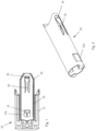
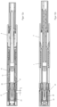
- the injection device has a horseshoe-shaped, in particular cylindrical, receiving housing 1 with a proximal end and a distal end.
- a cap 20 is arranged at the distal end of the receiving housing 1 and fastened to the receiving housing 1.
- the cap 20 has a sleeve section 21 which, like the receiving housing 1, extends around a longitudinal axis L of the injection device or the receiving housing 1.
- the distal end of the sleeve section 21 is essentially closed, so that access from the outside to the interior of the cap 20 is not possible or only possible with difficulty.
- the cap 20 is positively connected to the receiving housing 1, in particular snapped.
- the cap 20 has an engagement member 22 at its proximal end, which engages in a corresponding engagement countermember of the receiving housing 1, in particular is snapped thereto.
- the positive engagement can be released by a movement of the cap 20 around and/or along the longitudinal axis L, whereby the cap 20 can be removed from the receiving housing 1 with a movement along the longitudinal axis L.
- a preferably sleeve-shaped removal element 25, which can also be referred to or designed as a removal sleeve 25, is accommodated in a displaceable or non-displaceable manner with respect to the cap 20 along the longitudinal axis L - depending on the embodiment.
- a drive unit which has a drive housing 5, can be attached to the proximal end of the receiving housing 1.
- the drive housing 5 can be joined to the receiving housing 1 in a force-fitting and/or form-fitting and/or material-fitting manner, for example.
- the drive housing 5 can enclose a piston rod, for example, which can be part of the drive unit. By moving the piston rod in the distal direction, a product is dispensed from a product container 10.
- a product container 10 designed as a syringe is arranged in the receiving housing 1.
- the product container 10 has a product container section 12, which is in particular formed as a hollow cylinder and whose inner wall forms a sealing gap with a piston 13 slidably received in the product container section 12.
- a flange 16, which is also referred to as a finger flange, can optionally be arranged at the proximal end of the product container section 12.
- the product container section 12 tapers at its distal end to a needle holding section 14, which has a significantly smaller outer diameter than the product container section 12.
- the needle holding section 14 surrounds the proximal part of an injection needle 11 and is preferably permanently connected to it.
- the injection needle 11 protrudes from the needle holding section 14 in the distal direction.
- a needle protection cap 17 is detachably attached to the needle holding section 14, for example by form-fitting and/or frictional engagement.
- the needle protection cap 17 can be a so-called rigid needle shield or alternatively a soft needle shield.
- the needle protection cap 17 surrounds the injection needle 11 in such a way that its sterility is ensured with respect to the area surrounding the needle protection cap 17.
- the product container 10 can optionally be arranged in a sleeve-shaped product container holder 2, for example, and be tightly enclosed thereby.
- the tapered section of the product container section 12 can be supported on an inwardly projecting shoulder of the product container holder 2 in the distal direction.
- the flange 16 can be supported on the product container holder 2 in the distal direction.
- the product container holder 2 can hold the product container 10 on its product container section 12 in a frictionally engaged manner.
- the product container holder 2 can be arranged, for example, axially fixed or displaceable in the receiving housing 1.
- a needle protection sleeve 3 can optionally be arranged in the receiving housing 1, which can be moved in the proximal direction with respect to the receiving housing 1 to trigger a product release and can be moved in the distal direction after the product has been released in order to cover the tip of the injection needle 11 in order to reduce the risk of injury.
- Such needle protection sleeves 3 are known from the prior art, however, and can be regarded as an advantageous development of the invention.
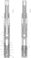
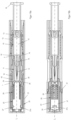
- the cap 20 accommodates the sleeve-shaped removal element 25.
- the cap 20 and a coupling section 27 of the removal element 25 engage with each other in such a way that the cap 20 limits the coupling section 27, in particular by a stroke h ( Figure 3a ) is displaceable along the longitudinal axis L in the distal direction.
- the removal element 25 forms in particular an axial stop against which a part of the cap 20 strikes at the end of the stroke h and thereby causes the removal element 25 to be carried along by the cap 20 when the cap 20 is moved along the longitudinal axis L and relative to the receiving housing 1 in the distal direction.
- the stroke h can also be referred to as the first partial stroke, for example, of a total stroke required for removing the cap 20 from the receiving housing 1.
- the coupling section 27 or generally the removal element 25 has a recess 27a into which a projection 24 formed by the cap 20 engages.
- the distal end of the recess 27a forms the axial stop for the projection 24, wherein the projection 24 abuts the distal end of the recess 27a at the end of the first partial stroke h.
- the cap 20 has an inner sleeve 23 which is arranged, for example, approximately concentrically to and in the sleeve section 21 and encloses or closely surrounds the removal element 25 on its outer circumference. This allows the The removal element 25 can be guided by the cap 20 so as to be displaceable along the longitudinal axis L. By guiding the removal element 25 through the inner sleeve 23, a lateral tipping of the removal element 25 can be reliably prevented.
- the removal element 25 has an engagement element 26 which is connected to the coupling section 27 via an arm, in particular a spring-loaded arm.
- the arm 29 is designed such that it enables a movement of the engagement element 26 transversely, in particular approximately radially to the longitudinal axis L.
- the engagement element 26 can be moved radially outwards, i.e. away from the longitudinal axis L, and spring back into its original position, i.e. towards the longitudinal axis L.
- the removal element 25 has an engagement element 26, for example, which is hook-shaped or projects inwards and which is in an engagement position in relation to the needle protection cap 17, in particular in the fully assembled state of the injection device, wherein in the engagement position a section of the needle protection cap 17 is arranged distally in alignment with the engagement element 26.
- the engagement element 26 engages in a gap 19 which is located between the proximal end of the needle protection cap 17 and the tapered transition from the product container section 12 into the needle holding section 14.
- the engagement element 26 could, for example, engage in a recess on the outer circumference of the needle protection cap in its engagement position or engage in the outer circumference of the needle protection cap 17 while deforming the needle protection cap 17.
- FIGS. 4a and 4b show the position of the engagement element 26 during insertion of the product container 10 in the distal direction before reaching the distal end position.
- the injection device is shown in the fully assembled state, with the engagement element 26 in the engagement position.
- the cap 20 has a blocking section 40 which is arranged in a release position proximal to the engagement element 26.
- the engagement member 22 is released from the corresponding engagement counter-member of the receiving housing 1 and the cap 20 is moved along the longitudinal axis L in the distal direction.
- the cap 20 thereby executes a first partial stroke h in the distal direction along the longitudinal axis L, whereby the blocking section 40 is also moved relative to the engagement element 26 by the first partial stroke h in the distal direction ( Figures 6a, 6b ).
- the cap 20 At the end of the first partial stroke h, the cap 20, in particular its projection 24, abuts against the axial stop of the removal element 25, in particular the distal end of the recess 27a, and the blocking section 40 is in its blocking position, namely in a position in which it blocks the movement of the engagement element 26 transversely outwards or away from the longitudinal axis L ( Figures 6a, 6b ).
- the removal element 25 and thus also the engagement element 26 and the needle protection cap 17 are taken along, e.g. during a second partial stroke, whereby the needle protection cap 17 is removed from the product container 10, in particular the needle holding section 14.
- the needle protection cap 17 is thus removed together with the cap 20 from the injection device or the receiving housing 1, whereby the injection needle 11 is exposed for a subsequent injection.
- the blocking section 40 By positioning the blocking section 40 in the blocking position, the engagement element 26 is prevented from coming out of engagement with the needle protection cap 17 during the removal of the cap 20 from the receiving housing 1. This ensures that the needle protection cap 17 is always removed together with the cap 20.
- the remover element 25 is connected to the cap 20 in a rotationally secured manner about the longitudinal axis L.
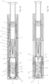
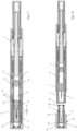
- the Figures 14 to 18 The third embodiment described has the sleeve-shaped removal element 25, which is connected to the cap 20 with its coupling section 27 in an axially fixed manner, ie not displaceable along the longitudinal axis L.
- the cap 20 has a projection 24 which engages in the recess 27a of the coupling section 27.
- the removal element 25 is connected to the cap 20 in a rotationally secured manner about the longitudinal axis L, in particular by means of the engagement of the projection 24 in the recess 27a.
- the engagement element 26 is connected to the coupling section 27 via a deformation section 28.
- the deformation section 28 is designed such that it can deform along the longitudinal axis L and in particular also transversely to the longitudinal axis L. In particular, it can deform such that its length I extending along the longitudinal axis L can be extended at least by the amount ⁇ I.
- the deformation section 28 can have one or more helical or meandering sections or webs along the longitudinal axis L, which connect the coupling section 27 and the engagement element 26.
- the deformation section 28 can have a plurality of ring-shaped elements arranged in a row along the longitudinal axis L, wherein adjacent ring-shaped elements are connected via a connecting web.
- the ring axis around which the rings extend is transverse, in particular substantially perpendicular to the longitudinal axis L.
- the rings can be flattened along the longitudinal axis L such that each of the rings encloses a slot-shaped cavity, wherein the slot width extends along the longitudinal axis L. In a mechanical sense, such an arrangement forms a plurality of idealized bending beams which bend and thus allow slight deformation when the length I is increased.
- the removal element 25 further comprises the blocking section 40 which, in the fully assembled state of the Injection device is arranged proximal to the engagement element 26.
- the engagement element 26 has an axial stop 42, which in the example shown consists of the Figures 14 and 15 is designed as a nose, e.g. produced by forming or punching, which projects outwards, ie away from the longitudinal axis L.
- the axial stop 42 is located along the longitudinal axis L in alignment with the blocking section 40.
- the blocking section 40 is connected to the coupling section 27 in a non-displaceable manner along the longitudinal axis L, for example via a connecting web.
- a connecting web In the example shown, there are two elongated connecting webs which connect the coupling section 27 to the blocking section 40.
- the blocking section 40 connects the two connecting webs on the circumference, with another blocking section 40 also being arranged on the opposite side, which connects the connecting webs on the circumference.
- the deformation section 28 is arranged in the circumferential direction between the connecting webs. Another essentially identical deformation section 28 is arranged opposite.
- the cap 20 To remove the cap 20, it is released from the positive engagement with the receiving housing 1 and initially moved by the first partial stroke h along the longitudinal axis in the distal direction. Because the coupling section 27 is axially firmly connected to the cap 20, the coupling section 27 and the blocking section 40 connected thereto in an immovable manner are taken along by the cap 20 during the first partial stroke h, while the engagement element 26 remains stationary relative to the receiving housing 1 or the product container 10 due to the engagement with the needle protection cap 17. As a result, the cap 20 and thus also the coupling section 27 are moved in the distal direction relative to the engagement element 26. At the same time, the blocking section 40 is moved from the release position to the blocking position ( Figure 15 ), the blocking section 40 striking the axial stop 42 in the blocking position.
- the blocking section 40 prevents a movement of the engagement element 26 transversely to the longitudinal axis L outwards, ie away from the longitudinal axis.
- the deformation section 28 is extended by the amount ⁇ I ( Figures 15 and 17 ).
- the blocking section 40 rests against the axial stop 42, the blocking section 40 takes the engagement element 26 along the longitudinal axis L in the distal direction during a further movement (second partial stroke), whereby the needle protection cap 17 is taken along and pulled off the product container holder 10, in particular the needle holding section 14 ( Figure 18 ).
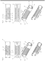
- the injection device comprises a sleeve-shaped removal element 25, which has a coupling section 27 which is connected to the cap 20 in an axially fixed, preferably rotationally and axially fixed manner.
- the cap 20 has a projection 24 which engages in a recess 27a of the coupling section 27 and causes the coupling section 27 to be immovable with respect to the cap 20 along the longitudinal axis L and preferably not to be rotated about the longitudinal axis L.
- the inwardly projecting engagement element 26 is connected to the coupling section 27 via a deformation section 28.
- the deformation section 28 is designed such that it can extend along the longitudinal axis L, whereby the length l is extended by the amount ⁇ l.
- the deformation section 28 constricts ( Figure 9 ), so that its inner diameter is reduced, in particular with respect to the inner diameter when the deformation section 28 has its original length l ( Figure 8 ).
- the deformation section 28 has at least one helix 31, 32, 33 which winds helically with at least one complete turn around the longitudinal axis L and connects the coupling section 27 to a base section 43.
- the engagement element 26 is connected to the base section 43 via an arm 29 such that the engagement element 26 can be moved transversely to the longitudinal axis L, in particular can be moved resiliently.
- the deformation section 28 has a plurality of helices 31, 32, 33, such as a first helix 31, a second helix 32 and a third helix 33, which each extend helically with at least one turn, here even more than two turns, around the longitudinal axis L and connect the coupling section 27 to the base section 43.
- Adjacent turns of the spirals 31, 32, 33 are connected via a connecting web.
- One or several or all of these connecting webs have an engagement cam 30 which projects inwards from the inner circumference of the deformation section 28, in particular with a tip of the engagement cam 30 directed in the distal direction.
- the product container 10 is inserted into the housing 1 ( Figures 10a, 10b ) and displaced in the distal direction until it reaches its distal end position, whereby the engagement element 26 springs into the gap 19 and assumes the engagement position.
- the engagement element 26 In the fully assembled state of the injection device, the engagement element 26 is in its engagement position ( Figures 11a, 11b ). To remove the cap 20, the positive engagement with the receiving housing 1 is first released and the cap 20 is moved by a distance or partial stroke x in the distal direction ( Figures 12a, 12b ), whereby the coupling section 27 and the cap 20 are moved relative to the engagement element 26, which is supported on the proximal end of the needle protection cap 17 in the proximal direction.
- the deformation section 28 is deformed by the amount ⁇ l ( Figure 9 ), the deformation section 28 constricting and the engagement cams 30 digging into the outer circumference or the outer peripheral surface of the needle protection cap 17, whereby the force exerted on the cap 20 is transmitted in the distal direction not only via the engagement element 26 to the needle protection cap 17, but also via the engagement cams 30 engaging in the needle protection cap 17. If the cap 20 is now moved further in the distal direction, the engagement of the needle protection cap 17 with the product container, in particular the needle holding section 14, is released, whereby the needle protection cap 17 is removed together with the cap 20 from the injection device ( Figures 13a, 13b ).
- the assembly process in particular the integration of the product container 10 in the receiving housing 1 of the injection device, is essentially similar in the three embodiments shown in the figures.
- the product container 10 is inserted into the product container holder 2 stored in the receiving housing 1.
- the product container holder 2 which in the examples shown is displaceable in relation to the receiving housing 1, is supported on the cap 20 to block its displaceability along the longitudinal axis L during assembly, thereby preventing displacement of the product container holder 2 in the distal direction when the cap 20 is attached to the receiving housing 1.
- the engagement element 26 slides off the needle protection cap 17 and is pressed radially outwards by the needle protection cap 17, in particular its outer peripheral surface.
- the blocking section 40 is in its release position and not in the blocking position ( Figures 4a, 4b , 16a, 16b ).
- the engagement of the removal element 25 with the needle protection cap 17 is increased by the constriction of the deformation section 28 when the cap 20 is pulled off.
- the engagement element 26 snaps into its engagement position between the tapered end of the product container section 12 and the proximal end of the needle protection cap 17.
- the drive housing 5 is then joined or connected to the receiving housing 1, whereby the injection device is completely assembled.
- a blocking section 40 which, when the cap 20 is removed in the second embodiment, which is not part of the invention, constricts and in the first and third embodiments moves relative to the engagement element either by partial stroke or by deformation, and thereby transfers at least part of the removal force applied to the cap 20 to the needle protection cap 17, in all embodiments the respective engagement elements 26 can be arranged on the removal element 25 in such a way that they can be moved or pivoted outwards, i.e. approximately radially away from the longitudinal axis L, with a relatively low force. This reduces the risk, which would exist, for example, with an engagement element that is too strong, that the needle protection cap 17 is moved by the engagement element on the needle holding section 14 of the product container 10 during insertion into the receiving housing. Movement of the needle protection cap 17 on the needle holding section 14 may endanger the sterility of the injection needle 11.
- the following shows an autoinjector that can be used with a pull cap, preferably but not necessarily a pull cap of the types described above.
- the autoinjector ( Figure 19 ) has a sleeve-shaped, elongated housing 102 with a longitudinal axis L, which has a closure cap 1012 at its proximal end, which is positively connected to the housing 102 in a rotationally and axially fixed manner and forms the proximal end of the autoinjector.
- the closure cap 1012 is snapped onto the housing 102.
- the closure cap 1012 has a locking member 1012a, which is locked into a recess 102a on the housing 102, preferably in such a way that the closure cap 1012 cannot be detached from the housing 102 or cannot be easily detached.
- a needle protection cap 20 (in Fig. 19 not shown) of the types described above, which is pulled off, or twisted off, and removed before using the auto-injector.
- a product container in the form of a syringe is accommodated in the housing 102 so that it cannot be moved along the longitudinal axis L with respect to the housing 102 - apart from the assembly of the auto-injector.
- the product container has a sleeve-shaped syringe body which surrounds a piston which lies sealingly against the inner circumference of the syringe body.
- the syringe body has an injection needle at its distal end which is in particular permanently connected to the syringe body and whose distal end is formed by the needle tip.
- a liquid product, in particular medication, is arranged within the syringe body between the injection needle and the piston, whereby the liquid product is dispensed from the product container through the hollow injection needle by moving the piston in a dispensing direction, i.e. in the distal direction or towards the injection needle.
- the syringe body has a so-called finger flange at its proximal end which projects radially outwards over the outer circumference of the cylindrical syringe body.
- the product container is accommodated in a product container holder, which is referred to as syringe holder 101, in such a way that it is secured at least against movement along the longitudinal axis L in the distal direction relative to the syringe holder 101.
- the syringe holder 101 is positively connected to the housing 102, in particular locked.
- the housing 102 has recesses for this purpose, into which locking elements, which are here at the proximal end of the syringe holder 101.
- the syringe holder 101 has at least one inwardly projecting shoulder 101b on which a tapered section of the product container is supported.
- the product container is pressed at its proximal end into engagement with the shoulder 101b by a holder acting on the syringe body.
- the holder is formed by a retaining spring section 105c of a mechanical holder 105.
- the mechanical holder 105 is arranged in particular immovably and/or rotationally fixed with respect to the housing 102 along the longitudinal axis L.
- the sleeve-shaped mechanical holder 105 can be snapped onto the housing 102.
- the retaining spring section 105c can compensate for differences in the length of the product container that can arise due to manufacturing tolerances, whereby the firm fit of the product container on the shoulder 101b is ensured.
- the product container is arranged in relation to the housing 102 such that the needle tip protrudes distally beyond the distal end of the housing 102.
- the needle is covered by a needle cover cap 17, which in the examples shown is designed as a so-called rigid needle shield known to those skilled in the art, or alternatively as a soft needle shield, in order to protect the needle from contamination and to keep the needle 13a and the medication sterile.
- the rigid needle shield is arranged on a needle holding section of the syringe body, with the tapered section of the syringe body being located between the needle holding section and the cylindrical section of the syringe body.
- the shoulder 101b is arranged between the syringe body and the proximal end of the rigid needle shield, in particular such that a gap - albeit a small one - is formed between the rigid needle shield and the shoulder 101b in order to prevent the shoulder 101b from exerting a force on the rigid needle shield, which could, for example, endanger the sterility of the needle or the liquid product.
- the pull cap 20 is releasably snapped to the housing 102 or a needle protection sleeve 103, this snapping being released when the pull cap 20 is removed from the housing 102 or the needle protection sleeve 103.
- the autoinjector has a needle protection sleeve 103 which can be moved relative to the housing 102 and along the longitudinal axis L by an actuation stroke H B in the proximal direction into an actuated position in order to trigger a product release.
- actuation stroke H B in the proximal direction into an actuated position in order to trigger a product release.
- the distal end of the needle protection sleeve 103 protrudes distally beyond the needle tip of the needle, so that access to the needle tip is initially prevented.
- the needle protection sleeve 103 By moving the needle protection sleeve 103 by the actuation stroke H B, the needle protection sleeve 103 is moved far enough in the proximal direction that the needle protrudes from the distal end of the needle protection sleeve 103, in particular protrudes with a length which corresponds to the injection depth of the needle into the puncture site.
- the needle should protrude far enough beyond the distal end of the needle protection sleeve 103 that a subcutaneous injection can take place.
- the housing 102 can form a stop against which the needle protection sleeve 103 rests in the actuated position.
- the needle protection sleeve 103 can be moved relative to the housing 102 from the actuated position along the longitudinal axis L by a needle protection stroke H N in the distal direction into a needle protection position.
- the needle protection position the distal end of the needle protection sleeve 103 protrudes distally beyond the needle tip, so that access to the needle tip is prevented and the risk of injury is reduced.
- the needle protection sleeve 103 can be blocked against being pushed back out of the needle protection position again, as described further below.
- the tip holder 101 has a projection 101a that points radially outward, wherein the projection 101a engages in a slot-shaped recess of the needle protection sleeve 103 that is arranged between the housing 102 and the syringe holder 101.
- the needle protection sleeve 103 In the starting position of the needle protection sleeve 103 and/or in the needle protection position of the needle protection sleeve 103, the needle protection sleeve 103, in particular the proximal end of the slot-shaped recess, rests against the projection 101a, thereby preventing movement of the needle protection sleeve 103 in the distal direction.
- a cam 101c which is arranged resiliently on the syringe holder 101 and is formed by the syringe holder 101, can engage in this slot-shaped recess, alternatively in another recess of the needle protection sleeve 103.
- the cam 101c is designed in such a way that when attempting to move the needle protection sleeve 103 from the starting position to the actuated position, the cam 101c initially prevents the needle protection sleeve 103 from moving, with the cam 101c being pushed out when the force applied to the needle protection sleeve 103 to push it back exceeds a certain threshold value, whereby the needle protection sleeve 103 is suddenly pushed back into the actuated position.
- the needle can thus be suddenly inserted into the puncture site.
- the distal end of the needle protection sleeve 103 is placed into the puncture site, wherein the housing 102 is then pressed in the direction of the puncture site, wherein when the pressing force exceeds the above-mentioned threshold value, the housing 102 is suddenly moved towards the puncture site and the needle protection sleeve 103 is moved relative to the housing 102 into the actuated position.
- the housing 102 has an annular holding portion or ring portion which surrounds the distal end of the syringe holder 101 in particular in a ring shape and rests against it, whereby the at least one shoulder 101b is held in engagement with the tapered region of the syringe body. Furthermore, the housing 102 has in the region of the holding section, a translation stop in the form of a holding shoulder, which prevents the syringe holder 101 from being displaced in the distal direction relative to the housing 102 when the syringe holder 1 rests against the holding shoulder. This also applies advantageously to the variants described.
- the auto-injector further comprises a sleeve-shaped propulsion member 107, which forms an inwardly projecting shoulder at its distal end, on which a first spring 109, which can also be referred to as a dispensing spring, is supported.
- the first spring 109 is arranged within the sleeve-shaped propulsion member 107.
- the second spring 109 is a helical spring that acts as a compression spring and, in the initial or delivery state of the auto-injector, is pre-tensioned with so much energy that it can dispense the product contained in the product container, in particular completely, from the product container by moving the propulsion member 107 by a dispensing stroke HA .
- there is a distance between the piston and the distal end of the propulsion member 107 so that the propulsion member 107 only strikes the piston during the execution of the dispensing stroke HA and carries it in the dispensing direction.
- the first spring 109 is supported with its proximal end on a holding element 106, which in this example has two arms 106c, with a first engagement element 106a and a second engagement element 106b arranged on each arm 106c.
- the first engagement element 106a points radially towards the longitudinal axis L, with the second engagement element 106b pointing radially away from the longitudinal axis L.
- the first engagement element 106a engages in a first recess 107a formed by the propulsion element 107, thereby preventing movement of the propulsion member 7 relative to the holding element 106 in the distal direction or in the dispensing direction. This holds the first spring 109 in its tensioned state.
- the holding element 6 has a guide pin 106d which is inserted through the proximal end of the first spring 109 into the core of the spring 109.
- the guide pin 106d prevents the first spring 109 from buckling sideways during and at the end of the discharge stroke HA of the propulsion member 107.
- the auto-injector has a switching module 108, 1015, which has a switching sleeve 1015 and a locking sleeve 108 surrounded by the switching sleeve 1015.
- the first engagement element 106a is held in engagement with the first recess 107a by the inner circumference of the locking sleeve 108, which rests against the second engagement element 106b.
- the switching sleeve 1015 is connected to the proximal end 103a of the needle protection sleeve 103 or at least rests against the proximal end 103a of the needle protection sleeve 103.
- a second spring 1010 within which the first spring 109 is arranged and which preferably at least partially surrounds the switching sleeve 1015 and the locking sleeve 108, is supported with its distal end on the switching sleeve 1015.
- a part of the switching sleeve 1015 is thus arranged between the needle protection sleeve 103 and the distal end of the second spring 1010.
- the second spring 1010 is a metal spring that acts as a compression spring and is designed as a coil spring.
- the second spring 1010 is supported with its proximal end on a signal element 1011, in particular on a projection 1011c, which engages in the housing 102 in an axially displaceable and torsion-proof manner and which reaches through a slot-shaped groove 105b of the mechanism holder 105.
- the second spring 1010 thus also surrounds the mechanism holder 105 at least partially, preferably completely.
- the switching element 1015 has a recess 1015a into which a locking element 8a of the locking sleeve 108 engages.
- the locking element 108a is sawtooth-shaped and projects radially away from the longitudinal axis L.
- the locking element 8a is arranged resiliently on an arm which is formed by the locking sleeve 108.
- the switching sleeve 1015 is also moved along by the actuation stroke H B , whereby the second spring 1010 is tensioned. If the needle protection sleeve 103 is not moved completely into the actuated position, the second spring 1010 can move the switching sleeve 1015 and the needle protection sleeve 103 back to the starting position, whereby the locking sleeve 108 is also moved along by the switching sleeve 1015 via the engagement of the locking member 108a.
- the particularly sleeve-shaped signaling member 1011 is in an axially fixed engagement with the propulsion member 107 in the delivery state or before the product dispensing is triggered.
- the signaling member 1011 has a first engagement member 1011a, which engages in a recess 107b of the propulsion member 107, and a second engagement member 1011b.
- the first engagement member 1011a and the second engagement member 1011b are spring-mounted at the end of an arm 1011d.
- the signaling member 1011 has two such arms 1011d with a first engagement member 1011a and a second engagement member 1011b.
- the first engagement member 1011a points radially toward the longitudinal axis L, with the second engagement member 1011b pointing radially away from the longitudinal axis L.
- the first engagement member 1011a is held in axially fixed engagement with the drive member 107 by the inner circumference of the locking sleeve 108.
- the second engagement member 1011b rests against the inner circumference of the switching sleeve 108.
- the closure cap 1012 has a signal stop 12b against which the signal member 1011 can strike in order to generate a signal and preferably against which the signal member 1011 rests in the delivery state of the device.
- the pull cap 20 is removed from the autoinjector together with the rigid needle shield.
- the distal end of the needle protection sleeve 103 is placed at the puncture site of a patient, the housing 102 being displaced towards the puncture site, whereby the needle protection sleeve 103 moves from its starting position by the actuation stroke H B in the proximal direction relative to the housing 102 into the actuated position.
- the locking sleeve 108 has a first recess 108b, which is brought to the position of the second engagement element 106b by displacing the locking sleeve 108 by the actuation stroke H B along the longitudinal axis L.
- the first engagement element 106a is moved out of engagement with the drive member 107 with a movement transverse to and away from the longitudinal axis L, while at the same time the second engagement element 106b is moved into engagement with the locking sleeve 108, in particular its first recess 108b.
- the drive member 107 is released for movement by the discharge stroke HA in the discharge direction.
- the holding element 106 which is movable at least a short distance relative to the housing 102 and along the longitudinal axis L, can be moved by the first spring 109 in the proximal direction, wherein the holding element 106 takes the locking sleeve 108 by a start signal stroke H K via the engagement of the second engagement element 106b in the recess 108b, whereby the locking sleeve 8 strikes a start signal stop 105a, which is formed by the mechanism holder 105, and thereby emits an acoustic and/or tactile signal, which signals to the user of the device that the product dispensing has started.
- the locking member 108a is released for movement transversely and towards the longitudinal axis L, since the mechanism holder 105 has a recess 105d which allows such a movement of the locking member 108a when the locking sleeve 8 has been displaced by the actuating stroke H B or when the needle protection sleeve 103 is in its actuated position.
- the signal member 1011 Since the signal member 1011 is still axially fixed to the drive member 107, it is driven by a first partial stroke H S of the discharge stroke H A in the discharge direction, wherein the signal member 1011 is moved away from the signal stop 1012b by approximately the first partial stroke Hs.
- the first engagement member 1011a At the end of the first partial stroke Hs, during which the first and second engagement members 1011a, 1011b are moved relative to the locking sleeve 108, the first engagement member 1011a is pressed out of engagement with the drive member 107, wherein at the same time the second engagement member 1011b is moved into the second recess 108c of the locking sleeve 8 with a movement transverse to the longitudinal axis L and radially away from the longitudinal axis L.
- the second engagement member 1011b is held by the outer circumference of the propulsion member 7 in engagement with the recess 108c when the propulsion member 107 is moved by its second partial stroke of the discharge stroke HA .
- the outer peripheral surface of the drive member 107 holds the second engagement element 106b in engagement with the first recess 108b of the locking sleeve 108.
- the drive member 107 releases the second engagement member 1011b from engagement with the locking sleeve 108, whereby the second engagement member 1011b is moved out of engagement with the recess 108c, in particular towards the longitudinal axis L, so that the second spring 1010 accelerates the signal member 1011 against the dispensing direction, ie in the proximal direction, so that when the signal member 1011 hits the signal stop 1012b, an acoustic and/or tactile signal is generated.
- the engagement of the second engagement element 106b in the first recess 108b remains, thereby preventing movement of the locking sleeve 108 in the distal direction relative to the housing 102.
- the second spring 1010 can move the switching sleeve 1015 and the needle protection sleeve 103 from the actuated position to the needle protection position by the needle protection stroke H N , whereby the locking member 108a is pushed out of engagement with the recess 1015a, whereby the switching sleeve 1015 moves in the distal direction relative to the locking sleeve 108.
- the locking member 108a snaps into the switching sleeve 1015, whereby the locking member 108a prevents the needle protection sleeve 103 from being pushed back into its actuated position.
- the switching element 1015 When attempting to push the needle protection sleeve 103 back from the needle protection position into the actuated position, the switching element 1015 hits the locking element 108a, which prevents the needle protection sleeve 103 from moving into the actuated position.
- the locking sleeve 108 is supported axially on the start signal stop 105a of the mechanism holder 105.
Landscapes
- Health & Medical Sciences (AREA)
- Engineering & Computer Science (AREA)
- Hematology (AREA)
- Anesthesiology (AREA)
- Biomedical Technology (AREA)
- Heart & Thoracic Surgery (AREA)
- Vascular Medicine (AREA)
- Life Sciences & Earth Sciences (AREA)
- Animal Behavior & Ethology (AREA)
- General Health & Medical Sciences (AREA)
- Public Health (AREA)
- Veterinary Medicine (AREA)
- Environmental & Geological Engineering (AREA)
- Infusion, Injection, And Reservoir Apparatuses (AREA)
Claims (6)
- Dispositif d'injection, comprenant :a) un contenant de produit (10) avec une aiguille d'injection (11),b) un capuchon de protection d'aiguille (17), qui est fixé de manière détachable sur le contenant de produit (10) et entoure l'aiguille d'injection (11) et l'étanchéifie de manière stérile vis-à-vis de l'environnement,c) un capuchon (20), qui est relié au capuchon de protection d'aiguille (17) par l'intermédiaire d'un élément de retrait (25), lequel présente un élément d'engagement (26), de sorte que le dispositif de retrait du capuchon (20) du dispositif d'injection provoque le retrait du capuchon de protection d'aiguille (17) du contenant de produit (10),d) dans lequel l'élément d'engagement (26) est dans une position d'engagement par rapport au capuchon de protection d'aiguille (17), dans lequel, dans la position d'engagement, une partie du capuchon de protection d'aiguille (17) est alignée distalement avec l'élément d'engagement (26), moyennant quoi l'élément d'engagement (26) appuie ou bute contre une extrémité proximale du capuchon de protection d'aiguille (17) lorsque l'élément d'enlèvement (25) est déplacé avec le capuchon (20) par rapport au capuchon de protection d'aiguille (17) dans la direction distale,e) dans lequel le capuchon (20) et l'élément d'engagement (26) sont accouplés de sorte que le capuchon (20) peut être déplacé ou est déplacé par rapport à l'élément d'engagement (26) pendant le retrait du dispositif d'injection, caractérisé en ce quef) le dispositif d'injection comprend une section de blocage (40), la section de blocage (40) étant couplée au capuchon (20) de telle sorte que la section de blocage (40) est disposée dans la position de libération depuis une position de libération, la section de blocage étant située dans la position de libération à proximité de l'élément d'engagement (26) et/ou de l'extrémité proximale du capuchon de protection d'aiguille (17), dans une position de blocage, et se trouve dans la position de libération lorsque le capuchon (20) est complètement attaché ou fixé à un boîtier de réception (1), et en ce que le retrait du capuchon (20) du boîtier de réception (1) déplace la section de blocage (40) d'une position de libération à une position de blocage,g) dans lequel la partie de blocage (40) est conçue de sorte que la mobilité de l'élément d'engagement (26) transversalement vers l'extérieur ne se bloque pas lorsque la partie de blocage (40) est dans sa position de libération, et dans lequel la partie de blocage (40) est réalisée de sorte que la mobilité de l'élément d'engagement (26) transversalement vers l'extérieur se bloque lorsque la partie de blocage (40) est dans sa position de blocage.
- Dispositif d'injection selon la revendication 1, caractérisé en ce que le capuchon (20) peut être déplacé ou est déplacé tout d'abord par rapport à l'élément d'engagement (26) pendant le retrait du dispositif d'injection et ensuite l'élément d'engagement (26) entraîne le mouvement du capuchon (20), ce qui a pour effet que le capuchon de protection d'aiguille (17) est retiré ou enlevé du contenant de produit (10).
- Dispositif d'injection selon la revendication 1 ou 2, caractérisé en ce que le capuchon (20) peut être ôté du dispositif d'injection avec un mouvement axial ou un mouvement rotatif axial combiné pendant le retrait du dispositif d'injection.
- Dispositif d'injection selon l'une quelconque des revendications 1 à 3, caractérisé en ce que le capuchon (20) est fixé de manière détachable sur le boîtier de réception (1), lequel entoure le contenant de produit.
- Dispositif d'injection selon l'une quelconque des revendications 1 à 4, caractérisé en ce que la partie de blocage (40) est formée par le capuchon (20), dans lequel il est préférable que le capuchon (20) présente un évidement (41) qui dans la position de libération de la partie de blocage (40) est le long de l'axe longitudinal (L) dans une position à hauteur de l'élément d'engagement (26), dans lequel la partie de blocage (40) est déplacée dans la position de blocage par retrait du capuchon (20).
- Dispositif d'injection selon l'une quelconque des revendications 1 à 4, caractérisé en ce que la partie de blocage (40) est formée par l'élément de retrait (25), dans lequel il est préférable que la partie de blocage (40) et l'élément d'engagement (26) soient reliés par l'intermédiaire d'une partie de déformation (28), qui se déforme pendant le mouvement de la partie de blocage (40) de la position de libération dans la position de blocage.
Applications Claiming Priority (2)
| Application Number | Priority Date | Filing Date | Title |
|---|---|---|---|
| CH00989/16A CH712753A2 (de) | 2016-07-28 | 2016-07-28 | Trennen einer Nadelschutzkappe von einem Produktbehälter und Verfahren zum Montieren einer Injektionsvorrichtung. |
| PCT/CH2017/000062 WO2018018165A1 (fr) | 2016-07-28 | 2017-06-21 | Capuchon externe doté d'un élément de retrait de protège-aiguille et procédé de montage d'un dispositif d'injection |
Publications (3)
| Publication Number | Publication Date |
|---|---|
| EP3490644A1 EP3490644A1 (fr) | 2019-06-05 |
| EP3490644B1 EP3490644B1 (fr) | 2021-05-26 |
| EP3490644B2 true EP3490644B2 (fr) | 2024-11-13 |
Family
ID=59257916
Family Applications (1)
| Application Number | Title | Priority Date | Filing Date |
|---|---|---|---|
| EP17734223.5A Active EP3490644B2 (fr) | 2016-07-28 | 2017-06-21 | Capuchon externe avec un élément pour décapouchonner un capuchon d'une syringe et une méthode d'assemblage d'une dispositif d'injection |
Country Status (4)
| Country | Link |
|---|---|
| US (1) | US11273265B2 (fr) |
| EP (1) | EP3490644B2 (fr) |
| CH (1) | CH712753A2 (fr) |
| WO (1) | WO2018018165A1 (fr) |
Families Citing this family (18)
| Publication number | Priority date | Publication date | Assignee | Title |
|---|---|---|---|---|
| CN113181477B (zh) | 2015-06-04 | 2023-07-14 | 麦迪麦珀医疗工程有限公司 | 用于药物释放装置的筒插入 |
| HRP20241251T1 (hr) | 2016-02-05 | 2024-12-06 | F. Hoffmann - La Roche Ag | Medicinski uređaj za otkrivanje najmanje jednog analita u tjelesnoj tekućini |
| SMT202400475T1 (it) | 2016-02-05 | 2025-01-14 | Hoffmann La Roche | Dispositivo medico per rilevare almeno un analita in un fluido corporeo |
| SMT202500057T1 (it) * | 2017-12-21 | 2025-03-12 | Hoffmann La Roche | Sistema medico e procedimento di fabbricazione dello stesso |
| JP7402799B2 (ja) | 2017-12-22 | 2023-12-21 | ウェスト ファーマ サービシーズ イスラエル リミテッド | サイズの異なるカートリッジを利用可能な注射器 |
| CA3099358A1 (fr) | 2018-05-24 | 2019-11-28 | Novartis Ag | Dispositif d'administration de medicament automatique |
| ES2959943T3 (es) * | 2018-10-05 | 2024-02-29 | Becton Dickinson France | Extractor de tapa de cobertura con compresión de la junta de estanqueidad |
| CN113474025B (zh) | 2019-02-26 | 2023-12-01 | 贝克顿迪金森法国公司 | 具有声频指示器的自动注射器 |
| CN113490521B (zh) | 2019-02-26 | 2023-05-02 | 贝克顿迪金森法国公司 | 带有帽的自动注射器 |
| KR102615193B1 (ko) | 2019-02-26 | 2023-12-19 | 벡톤 디킨슨 프랑스 | 자동 주사 장치를 위한 낙하 테스트 특징부를 구비한 강성 바늘 쉴드 분리기 |
| EP3946517A1 (fr) * | 2019-04-04 | 2022-02-09 | Sanofi | Ensemble pour dispositif d'administration de médicament |
| EP4103251B1 (fr) * | 2020-02-11 | 2025-06-04 | Ypsomed AG | Auto-injecteur équipé d'un manchon de protection d'aiguille |
| US12005244B2 (en) * | 2020-03-27 | 2024-06-11 | Medivena Sp. Z O.O. | Needle-based device based on direct wing-based coupling of a needle shield to a barrel thereof and safety mechanism implemented therein |
| CH717905A2 (de) * | 2020-09-30 | 2022-03-31 | Ypsomed Ag | Autoinjektor mit Ausschüttstopp. |
| EP4237049A4 (fr) * | 2020-10-27 | 2024-08-28 | Becton, Dickinson and Company | Système d'administration de médicament, et appareil de barrière et tirette pour celui-ci |
| USD948715S1 (en) | 2020-11-06 | 2022-04-12 | West Pharmaceutical Services, Inc. | Injection needle shield puller |
| CA3195450A1 (fr) * | 2020-11-13 | 2022-05-19 | Anders Holmqvist | Dispositif d'administration de medicaments |
| USD999906S1 (en) | 2021-06-24 | 2023-09-26 | UCB Biopharma SRL | Gripper for auto-injector needle shield |
Family Cites Families (99)
| Publication number | Priority date | Publication date | Assignee | Title |
|---|---|---|---|---|
| GB9506087D0 (en) | 1995-03-24 | 1995-05-10 | Owen Mumford Ltd | Improvements relating to medical injection devices |
| US5843036A (en) | 1996-08-23 | 1998-12-01 | Becton Dickinson And Company | Non-dosing cartridge for an injection device |
| FR2812817B1 (fr) | 2000-08-09 | 2002-10-31 | Sanofi Synthelabo | Dispositif de protection d'une aiguille de seringue |
| ES2605734T3 (es) | 2001-12-13 | 2017-03-16 | Becton, Dickinson And Company | Dispositivo extractor de sistema de cierre de aguja |
| GB0403335D0 (en) | 2004-02-14 | 2004-03-17 | Liversidge Barry P | Medical injector handling device |
| GB2414400B (en) | 2004-05-28 | 2009-01-14 | Cilag Ag Int | Injection device |
| GB2425062B (en) | 2005-04-06 | 2010-07-21 | Cilag Ag Int | Injection device |
| GB2424836B (en) | 2005-04-06 | 2010-09-22 | Cilag Ag Int | Injection device (bayonet cap removal) |
| GB2438590B (en) | 2006-06-01 | 2011-02-09 | Cilag Gmbh Int | Injection device |
| GB2438593B (en) | 2006-06-01 | 2011-03-30 | Cilag Gmbh Int | Injection device (cap removal feature) |
| FR2905273B1 (fr) | 2006-09-06 | 2009-04-03 | Becton Dickinson France Soc Pa | Dispositif d'injection automatique avec moyen de temporisation. |
| US20080228147A1 (en) | 2007-03-15 | 2008-09-18 | Bristol-Myers Squibb Company | Injector for use with pre-filled syringes and method of assembly |
| US8512312B2 (en) * | 2007-05-01 | 2013-08-20 | Medtronic, Inc. | Offset catheter connector, system and method |
| GB2451663B (en) | 2007-08-08 | 2012-09-26 | Cilag Gmbh Int | Injection device |
| GB2451665B (en) | 2007-08-08 | 2012-09-26 | Cilag Gmbh Int | Injection device |
| US8814828B2 (en) | 2007-09-25 | 2014-08-26 | Becton Dickinson France | Autoinjector with deshielder comprising tamper evidence means |
| US8313470B2 (en) | 2007-09-25 | 2012-11-20 | Becton Dickinson France | Autoinjector |
| FR2922457B1 (fr) | 2007-10-23 | 2010-10-29 | Plastef Investissements | Dispositif de seringue a capuchon de protection. |
| GB0724944D0 (en) | 2007-12-20 | 2008-01-30 | Ucb Pharma Sa | Auto injector |
| GB0800103D0 (en) | 2008-01-04 | 2008-02-13 | Owen Mumford Ltd | Sheath removver device |
| DK2240222T3 (en) | 2008-01-11 | 2018-06-25 | Ucb Biopharma Sprl | SYSTEMS FOR THE ADMINISTRATION OF PHARMACEUTICALS FOR PATIENTS WITH RHEUMATOID ARTHRITIS |
| CN101925374B (zh) | 2008-01-23 | 2014-11-26 | 诺沃-诺迪斯克有限公司 | 用于注射所分配剂量的液体药物的设备 |
| WO2010034356A1 (fr) | 2008-09-29 | 2010-04-01 | Vifor (International) Ag | Ensemble capuchon et procédé de production |
| GB2465389A (en) | 2008-11-17 | 2010-05-19 | Owen Mumford Ltd | Syringe needle cover remover |
| GB2465390A (en) | 2008-11-17 | 2010-05-19 | Owen Mumford Ltd | Syringe needle cover remover |
| GB0900930D0 (en) | 2009-01-20 | 2009-03-04 | Future Injection Technologies Ltd | Injection device |
| GB0901801D0 (en) | 2009-02-05 | 2009-03-11 | Medical House Plc The | Improved autoinjector |
| EP2238999A1 (fr) | 2009-04-02 | 2010-10-13 | Vincent Pongpairochana | Dispositif d'injection automatique |
| DK2255842T4 (da) | 2009-05-26 | 2023-07-24 | Shl Medical Ag | Nålekappeaggregat |
| WO2010136076A1 (fr) | 2009-05-29 | 2010-12-02 | Tecpharma Licensing Ag | Dispositif d'injection comprenant un système destiné à séparer un capuchon de protection d'aiguille d'un réservoir à produit |
| WO2010142813A1 (fr) | 2009-06-12 | 2010-12-16 | Novo Nordisk A/S | Dispositif d'administration de médicament avec capuchon à fonctions pour ensemble aiguille |
| GB2471473A (en) | 2009-06-30 | 2011-01-05 | Owen Mumford Ltd | Syringe sheath remover |
| GB2472578A (en) | 2009-08-10 | 2011-02-16 | Owen Mumford Ltd | Sheath removal device and needle protector |
| WO2011022559A1 (fr) | 2009-08-19 | 2011-02-24 | Safety Syringes, Inc. | Dispositif de sécurité actif contre les piqûres d'aiguille en contact avec un patient |
| CA2789561A1 (fr) | 2010-02-18 | 2011-08-25 | Sanofi-Aventis Deutschland Gmbh | Gaine d'aiguille pour un dispositif d'injection |
| JP5820401B2 (ja) | 2010-02-22 | 2015-11-24 | サノフィ−アベンティス・ドイチュラント・ゲゼルシャフト・ミット・ベシュレンクテル・ハフツング | ニードルシールド及び針保護キャップを備えた自動注射器 |
| CN102971034B (zh) | 2010-05-20 | 2015-01-21 | Shl集团有限责任公司 | 药物输送设备 |
| WO2012023938A1 (fr) | 2010-08-19 | 2012-02-23 | West Pharmaceutical Services, Inc. | Gaine d'aiguille rigide |
| GB2484490A (en) | 2010-10-12 | 2012-04-18 | Owen Mumford Ltd | Frangible needle shield for syringe |
| WO2012082818A2 (fr) | 2010-12-14 | 2012-06-21 | West Pharmaceutical Services, Inc. | Dispositif de retrait d'un protecteur d'aiguille à partir d'une seringue et son procédé d'utilisation |
| ES2572656T3 (es) | 2010-12-14 | 2016-06-01 | Becton Dickinson France | Dispositivo de inyección compacto |
| EP2468338A1 (fr) | 2010-12-21 | 2012-06-27 | Sanofi-Aventis Deutschland GmbH | Auto-injecteur |
| GB2486690B (en) | 2010-12-22 | 2016-12-28 | Owen Mumford Ltd | Autoinjectors |
| GB201021764D0 (en) | 2010-12-22 | 2011-02-02 | Owen Mumford Ltd | Autoinjectors |
| GB2486693B (en) | 2010-12-22 | 2016-05-18 | Owen Mumford Ltd | Autoinjectors and manufacturing systems thereof |
| UA112308C2 (uk) | 2011-01-24 | 2016-08-25 | Еббві Байотекнолоджи Лтд. | Знімання кожухів голки зі шприців і автоматичних ін'єкційних пристроїв |
| HUE042822T2 (hu) | 2011-04-20 | 2019-07-29 | Amgen Inc | Automata befecskendezõ szerkezet |
| EP2729203B2 (fr) | 2011-07-05 | 2023-09-13 | SHL Group AB | Ensemble de retrait de gaine d'aiguille |
| ITFI20110193A1 (it) | 2011-09-08 | 2013-03-09 | Menarini Int Operations Lu Sa | Dispositivo per l'iniezione automatica di due dosi di farmaco |
| GB2494453B (en) | 2011-09-12 | 2013-08-07 | Owen Mumford Ltd | Injector assembly |
| CN104080498B (zh) | 2011-09-22 | 2016-08-24 | 艾伯维公司 | 自动注射装置 |
| BR112014009229A8 (pt) | 2011-10-17 | 2017-06-20 | Shl Group Ab | dispositivo para remover protetores de membro de dispensação |
| WO2013085454A1 (fr) | 2011-12-06 | 2013-06-13 | Shl Group Ab | Dispositif d'injection |
| KR101621183B1 (ko) | 2011-12-15 | 2016-05-23 | 에스에이치엘 그룹 에이비 | 캡 조립체 |
| PT2812051T (pt) | 2012-02-06 | 2017-01-09 | Unitract Syringe Pty Ltd | Subconjuntos de êmbolo e auto-injetores que têm baixa força de ativação de retração |
| CN106913938B (zh) | 2012-03-14 | 2020-02-21 | 艾斯曲尔医疗公司 | 药剂输送装置 |
| US9278179B2 (en) | 2012-06-20 | 2016-03-08 | Safety Syringes, Inc. | Contact trigger release needle guard with elastic spring |
| JP6549035B2 (ja) | 2012-10-19 | 2019-07-24 | アムゲン・インコーポレーテッド | 改良された自動注射器 |
| GB201218913D0 (en) | 2012-10-22 | 2012-12-05 | Ucb Pharma Sa | Auto-injector and drive unit therefor |
| FR2999436B1 (fr) | 2012-12-14 | 2016-02-05 | Transformation Des Elastomeres A Usages Medicaux Et Ind Soc D | Systeme de protection d'aiguille d'un dispositif d'injection. |
| EP2781230B2 (fr) | 2013-03-22 | 2025-05-14 | Ypsomed AG | Dispositif de distribution de substances avec dispositif de signal |
| DK2978478T3 (da) | 2013-03-25 | 2021-08-02 | Shl Medical Ag | Beskyttelseshætte til en medikamentafgivelsesanordning |
| EP2823841A1 (fr) | 2013-07-09 | 2015-01-14 | Sanofi-Aventis Deutschland GmbH | Auto-injecteur |
| EP2826509A1 (fr) | 2013-07-18 | 2015-01-21 | Sanofi-Aventis Deutschland GmbH | Éliminateur de protection d'aiguille |
| DK3038683T3 (en) | 2013-08-29 | 2018-11-12 | Sanofi Sa | SAFETY DEVICE FOR A MEDICINAL CONTAINER |
| FR3011186B1 (fr) | 2013-09-30 | 2017-12-08 | Rexam Healthcare La Verpillier | Dispositif de reception pour une seringue d'injection comprenant un capuchon de protection de l'aiguille |
| EP2878320A1 (fr) | 2013-11-28 | 2015-06-03 | Sanofi-Aventis Deutschland GmbH | Dispositif de retrait de gaine |
| EP2878321A1 (fr) * | 2013-11-28 | 2015-06-03 | Sanofi-Aventis Deutschland GmbH | Dispositif de sécurité d'aiguille et dispositif d'administration de médicament |
| EP2878319A1 (fr) | 2013-11-28 | 2015-06-03 | Sanofi-Aventis Deutschland GmbH | Dispositif de retrait de gaine |
| EP2878322A1 (fr) | 2013-11-28 | 2015-06-03 | Sanofi-Aventis Deutschland GmbH | Extracteur de bouchon d'aiguille et dispositif d'administration de médicament |
| EP2878323A1 (fr) | 2013-11-28 | 2015-06-03 | Sanofi-Aventis Deutschland GmbH | Dispositif d'administration de médicaments avec protecteur d'aiguille pourvue d'un enleveur d'un bouchon d'aiguille |
| EP2886146A1 (fr) | 2013-12-20 | 2015-06-24 | Sanofi-Aventis Deutschland GmbH | Dispositif de sécurité d'aiguille et dispositif d'administration de médicament |
| US9821123B2 (en) * | 2014-01-27 | 2017-11-21 | Ucb Biopharma Sprl | Auto-injector |
| PL2745866T3 (pl) | 2014-01-30 | 2017-04-28 | Tecpharma Licensing Ag | Zabezpieczenie przed uruchomieniem automatycznego iniektora |
| US20150351767A1 (en) * | 2014-02-06 | 2015-12-10 | Boston Scientific Scimed, Inc. | Methods, compositions, devices and kits for anastomoses |
| HK1226341A1 (zh) | 2014-02-11 | 2017-09-29 | Eli Lilly And Company | 抓取刚性针罩的盖组件 |
| EP2923716A1 (fr) * | 2014-03-28 | 2015-09-30 | Sanofi-Aventis Deutschland GmbH | Bouchon doté d'un mécanisme de retrait de gaine |
| WO2015169608A1 (fr) | 2014-05-06 | 2015-11-12 | Carebay Europe Ltd | Dispositif de distribution de médicament avec rotateur retenant la tige de piston |
| US10500353B2 (en) | 2014-10-08 | 2019-12-10 | SHL Medical, AG | Medicament delivery device |
| PL3226944T5 (pl) | 2014-12-03 | 2023-01-30 | Eli Lilly And Company | Zespół ściągacza osłony igły z nasadką |
| US10661014B2 (en) | 2015-01-21 | 2020-05-26 | Antares Pharma, Inc. | Injection device having variable dosing |
| GB2538701A (en) | 2015-04-30 | 2016-11-30 | Owen Mumford Ltd | Injection device |
| GB2538486A (en) | 2015-04-30 | 2016-11-23 | Owen Mumford Ltd | Injection Device |
| GB2538068A (en) | 2015-04-30 | 2016-11-09 | Owen Mumford Ltd | Injection devices |
| TW201707741A (zh) | 2015-06-03 | 2017-03-01 | 賽諾菲阿凡提斯德意志有限公司 | 針頭護罩之抓握器、蓋子、自動注射器及製造抓握器之方法 |
| TW201711716A (zh) | 2015-06-03 | 2017-04-01 | 賽諾菲阿凡提斯德意志有限公司 | 護罩鎖 |
| HK1248625A1 (zh) | 2015-06-18 | 2018-10-19 | Sanofi-Aventis Deutschland Gmbh | 用於覆盖针罩的盖组件以及用於装配盖组件的方法 |
| EP3117854A1 (fr) | 2015-07-15 | 2017-01-18 | Sanofi-Aventis Deutschland GmbH | Dispositif d'administration de medicaments avec un mécanisme de contrôle du protecteur d'aiguille et d'activation du dispositif |
| DK3325051T3 (da) | 2015-07-23 | 2019-10-21 | Shl Medical Ag | Variabel enkeltdosisinjektor |
| GB2541227A (en) | 2015-08-13 | 2017-02-15 | Owen Mumford Ltd | Injector Device |
| FR3043562B1 (fr) | 2015-11-13 | 2022-01-21 | Aptar France Sas | Autoinjecteur. |
| FR3047902B1 (fr) | 2016-02-19 | 2021-09-24 | Nemera La Verpilliere | Dispositif d'injection d'un produit liquide a assemblage simplifie. |
| US10661024B2 (en) | 2016-03-23 | 2020-05-26 | West Pharmaceutical Services, Inc. | Two piece needle shield puller |
| DK3458131T3 (da) | 2016-05-18 | 2022-05-23 | Sanofi Aventis Deutschland | Hylsterfjerner og fremgangsmåder til samling deraf |
| JP6785319B2 (ja) | 2016-06-03 | 2020-11-18 | エス・ハー・エル・メディカル・アクチェンゲゼルシャフトShl Medical Ag | 薬剤送達装置 |
| US10335553B2 (en) | 2016-06-13 | 2019-07-02 | Shl Medical Ag | Cap assembly for a medicament delivery device |
| US10363378B2 (en) | 2016-06-15 | 2019-07-30 | Shl Medical Ag | Cap assembly for medicament delivery device |
| WO2018011417A1 (fr) | 2016-07-15 | 2018-01-18 | Novo Nordisk A/S | Injecteur médical doté d'une caractéristique de sécurité empêchant l'expulsion accidentelle |
| US10300214B2 (en) | 2016-07-27 | 2019-05-28 | Shl Medical Ag | Cap assembly for a medicament delivery device |
-
2016
- 2016-07-28 CH CH00989/16A patent/CH712753A2/de not_active Application Discontinuation
-
2017
- 2017-06-21 EP EP17734223.5A patent/EP3490644B2/fr active Active
- 2017-06-21 WO PCT/CH2017/000062 patent/WO2018018165A1/fr not_active Ceased
-
2019
- 2019-01-28 US US16/259,524 patent/US11273265B2/en active Active
Also Published As
| Publication number | Publication date |
|---|---|
| EP3490644A1 (fr) | 2019-06-05 |
| EP3490644B1 (fr) | 2021-05-26 |
| WO2018018165A1 (fr) | 2018-02-01 |
| CH712753A2 (de) | 2018-01-31 |
| US20190151564A1 (en) | 2019-05-23 |
| US11273265B2 (en) | 2022-03-15 |
Similar Documents
| Publication | Publication Date | Title |
|---|---|---|
| EP3490644B2 (fr) | Capuchon externe avec un élément pour décapouchonner un capuchon d'une syringe et une méthode d'assemblage d'une dispositif d'injection | |
| EP3490647B1 (fr) | Dispositif d'injection avec un capuchon externe avec un élément pour décapouchonner un capuchon d'une aiguille et une méthode d'assemblage d'une dispositif d'injection | |
| EP3113811B1 (fr) | Auto-injecteur avec mode de déclenche éligible | |
| EP3610908B1 (fr) | Auto-injecteur avec protecteur d'aiguille mobile | |
| EP3421067B1 (fr) | Dispositif d'injection, notamment auto-injecteur comprenant une protection contre la piqûre involontaire et/ou une sécurité contre la surcharge, pour un réservoir à produit | |
| CH717267A2 (de) | Autoinjektor mit einem Mehrkammerproduktbehälter. | |
| EP3490641B1 (fr) | Dispositif d'injection doté d'un capuchon protecteur et d'un dispositif empêchant le repositionnement du capuchon protecteur | |
| CH717046A2 (de) | Autoinjektor mit einer Nadelschutzhülse. | |
| EP1684830A1 (fr) | Dispositif pour administrer un produit a injecter | |
| EP3727527B1 (fr) | Dispositif d'injection présentant un capuchon pour enlever un capuchon de protection d'aiguille d'un récipient de produit et procédé pour la préparation d'un tel dispositif d'injection | |
| WO2020164910A1 (fr) | Porte-seringue modulaire et procédé de montage de seringue | |
| EP3946521A1 (fr) | Dispositif d'injection présentant un capuchon pour retirer un capuchon de protection d'aiguille d'un récipient de produit et procédé de montage d'un dispositif d'injection | |
| EP3675937A1 (fr) | Dispositif d'entraînement pour appareils d'injection | |
| CH714527A2 (de) | Injektionsvorrichtung mit einer Kappe zur Entfernung einer Nadelschutzkappe von einem Produktbehälter und Verfahren zum Montieren einer Injektionsvorrichtung. | |
| CH712891A2 (de) | Injektionsvorrichtung mit einer Kappe zur Entfernung einer Nadelschutzkappe von einem Produktbehälter und Verfahren zum Montieren einer Injektionsvorrichtung. | |
| CH714526A2 (de) | Injektionsvorrichtung mit einer Kappe zur Entfernung einer Nadelschutzkappe von einem Produktbehälter und Verfahren zum Montieren einer Injektionsvorrichtung. | |
| CH714528A2 (de) | Injektionsvorrichtung mit einer Kappe zur Entfernung einer Nadelschutzkappe von einem Produktbehälter und Verfahren zum Montieren einer Injektionsvorrichtung. | |
| EP4275722A1 (fr) | Injecteur automatique pourvu de dispositif de réception de récipient de produit | |
| EP4552674A1 (fr) | Auto-injecteur avec manchon de verrouillage | |
| EP4262938A1 (fr) | Dispositif d'injection doté d'un capuchon pour retirer un capuchon de protection d'aiguille d'un récipient de produit, et procédé de préparation d'un tel dispositif | |
| WO2026017289A1 (fr) | Autoinjecteur comprenant un manchon de verrouillage | |
| CH718181A2 (de) | Injektionsvorrichtung mit einer Kappe zur Entfernung einer Nadelschutzkappe von einem Produktbehälter und Verfahren zum Vorbereiten einer solchen Vorrichtung. |
Legal Events
| Date | Code | Title | Description |
|---|---|---|---|
| STAA | Information on the status of an ep patent application or granted ep patent |
Free format text: STATUS: UNKNOWN |
|
| STAA | Information on the status of an ep patent application or granted ep patent |
Free format text: STATUS: THE INTERNATIONAL PUBLICATION HAS BEEN MADE |
|
| PUAI | Public reference made under article 153(3) epc to a published international application that has entered the european phase |
Free format text: ORIGINAL CODE: 0009012 |
|
| STAA | Information on the status of an ep patent application or granted ep patent |
Free format text: STATUS: REQUEST FOR EXAMINATION WAS MADE |
|
| 17P | Request for examination filed |
Effective date: 20190228 |
|
| AK | Designated contracting states |
Kind code of ref document: A1 Designated state(s): AL AT BE BG CH CY CZ DE DK EE ES FI FR GB GR HR HU IE IS IT LI LT LU LV MC MK MT NL NO PL PT RO RS SE SI SK SM TR |
|
| AX | Request for extension of the european patent |
Extension state: BA ME |
|
| DAV | Request for validation of the european patent (deleted) | ||
| DAX | Request for extension of the european patent (deleted) | ||
| STAA | Information on the status of an ep patent application or granted ep patent |
Free format text: STATUS: EXAMINATION IS IN PROGRESS |
|
| 17Q | First examination report despatched |
Effective date: 20200407 |
|
| RAP1 | Party data changed (applicant data changed or rights of an application transferred) |
Owner name: YPSOMED AG |
|
| GRAP | Despatch of communication of intention to grant a patent |
Free format text: ORIGINAL CODE: EPIDOSNIGR1 |
|
| STAA | Information on the status of an ep patent application or granted ep patent |
Free format text: STATUS: GRANT OF PATENT IS INTENDED |
|
| INTG | Intention to grant announced |
Effective date: 20210211 |
|
| GRAS | Grant fee paid |
Free format text: ORIGINAL CODE: EPIDOSNIGR3 |
|
| GRAA | (expected) grant |
Free format text: ORIGINAL CODE: 0009210 |
|
| STAA | Information on the status of an ep patent application or granted ep patent |
Free format text: STATUS: THE PATENT HAS BEEN GRANTED |
|
| AK | Designated contracting states |
Kind code of ref document: B1 Designated state(s): AL AT BE BG CH CY CZ DE DK EE ES FI FR GB GR HR HU IE IS IT LI LT LU LV MC MK MT NL NO PL PT RO RS SE SI SK SM TR |
|
| REG | Reference to a national code |
Ref country code: GB Ref legal event code: FG4D Free format text: NOT ENGLISH |
|
| REG | Reference to a national code |
Ref country code: CH Ref legal event code: EP |
|
| REG | Reference to a national code |
Ref country code: AT Ref legal event code: REF Ref document number: 1395583 Country of ref document: AT Kind code of ref document: T Effective date: 20210615 |
|
| REG | Reference to a national code |
Ref country code: DE Ref legal event code: R096 Ref document number: 502017010466 Country of ref document: DE |
|
| REG | Reference to a national code |
Ref country code: IE Ref legal event code: FG4D Free format text: LANGUAGE OF EP DOCUMENT: GERMAN |
|
| REG | Reference to a national code |
Ref country code: LT Ref legal event code: MG9D |
|
| PG25 | Lapsed in a contracting state [announced via postgrant information from national office to epo] |
Ref country code: HR Free format text: LAPSE BECAUSE OF FAILURE TO SUBMIT A TRANSLATION OF THE DESCRIPTION OR TO PAY THE FEE WITHIN THE PRESCRIBED TIME-LIMIT Effective date: 20210526 Ref country code: BG Free format text: LAPSE BECAUSE OF FAILURE TO SUBMIT A TRANSLATION OF THE DESCRIPTION OR TO PAY THE FEE WITHIN THE PRESCRIBED TIME-LIMIT Effective date: 20210826 Ref country code: LT Free format text: LAPSE BECAUSE OF FAILURE TO SUBMIT A TRANSLATION OF THE DESCRIPTION OR TO PAY THE FEE WITHIN THE PRESCRIBED TIME-LIMIT Effective date: 20210526 Ref country code: FI Free format text: LAPSE BECAUSE OF FAILURE TO SUBMIT A TRANSLATION OF THE DESCRIPTION OR TO PAY THE FEE WITHIN THE PRESCRIBED TIME-LIMIT Effective date: 20210526 |
|
| REG | Reference to a national code |
Ref country code: NL Ref legal event code: MP Effective date: 20210526 |
|
| PG25 | Lapsed in a contracting state [announced via postgrant information from national office to epo] |
Ref country code: LV Free format text: LAPSE BECAUSE OF FAILURE TO SUBMIT A TRANSLATION OF THE DESCRIPTION OR TO PAY THE FEE WITHIN THE PRESCRIBED TIME-LIMIT Effective date: 20210526 Ref country code: IS Free format text: LAPSE BECAUSE OF FAILURE TO SUBMIT A TRANSLATION OF THE DESCRIPTION OR TO PAY THE FEE WITHIN THE PRESCRIBED TIME-LIMIT Effective date: 20210926 Ref country code: GR Free format text: LAPSE BECAUSE OF FAILURE TO SUBMIT A TRANSLATION OF THE DESCRIPTION OR TO PAY THE FEE WITHIN THE PRESCRIBED TIME-LIMIT Effective date: 20210827 Ref country code: PL Free format text: LAPSE BECAUSE OF FAILURE TO SUBMIT A TRANSLATION OF THE DESCRIPTION OR TO PAY THE FEE WITHIN THE PRESCRIBED TIME-LIMIT Effective date: 20210526 Ref country code: PT Free format text: LAPSE BECAUSE OF FAILURE TO SUBMIT A TRANSLATION OF THE DESCRIPTION OR TO PAY THE FEE WITHIN THE PRESCRIBED TIME-LIMIT Effective date: 20210927 Ref country code: NO Free format text: LAPSE BECAUSE OF FAILURE TO SUBMIT A TRANSLATION OF THE DESCRIPTION OR TO PAY THE FEE WITHIN THE PRESCRIBED TIME-LIMIT Effective date: 20210826 Ref country code: SE Free format text: LAPSE BECAUSE OF FAILURE TO SUBMIT A TRANSLATION OF THE DESCRIPTION OR TO PAY THE FEE WITHIN THE PRESCRIBED TIME-LIMIT Effective date: 20210526 Ref country code: RS Free format text: LAPSE BECAUSE OF FAILURE TO SUBMIT A TRANSLATION OF THE DESCRIPTION OR TO PAY THE FEE WITHIN THE PRESCRIBED TIME-LIMIT Effective date: 20210526 |
|
| PG25 | Lapsed in a contracting state [announced via postgrant information from national office to epo] |
Ref country code: NL Free format text: LAPSE BECAUSE OF FAILURE TO SUBMIT A TRANSLATION OF THE DESCRIPTION OR TO PAY THE FEE WITHIN THE PRESCRIBED TIME-LIMIT Effective date: 20210526 |
|
| REG | Reference to a national code |
Ref country code: DE Ref legal event code: R026 Ref document number: 502017010466 Country of ref document: DE |
|
| PLBI | Opposition filed |
Free format text: ORIGINAL CODE: 0009260 |
|
| PG25 | Lapsed in a contracting state [announced via postgrant information from national office to epo] |
Ref country code: CZ Free format text: LAPSE BECAUSE OF FAILURE TO SUBMIT A TRANSLATION OF THE DESCRIPTION OR TO PAY THE FEE WITHIN THE PRESCRIBED TIME-LIMIT Effective date: 20210526 Ref country code: EE Free format text: LAPSE BECAUSE OF FAILURE TO SUBMIT A TRANSLATION OF THE DESCRIPTION OR TO PAY THE FEE WITHIN THE PRESCRIBED TIME-LIMIT Effective date: 20210526 Ref country code: DK Free format text: LAPSE BECAUSE OF FAILURE TO SUBMIT A TRANSLATION OF THE DESCRIPTION OR TO PAY THE FEE WITHIN THE PRESCRIBED TIME-LIMIT Effective date: 20210526 Ref country code: ES Free format text: LAPSE BECAUSE OF FAILURE TO SUBMIT A TRANSLATION OF THE DESCRIPTION OR TO PAY THE FEE WITHIN THE PRESCRIBED TIME-LIMIT Effective date: 20210526 Ref country code: RO Free format text: LAPSE BECAUSE OF FAILURE TO SUBMIT A TRANSLATION OF THE DESCRIPTION OR TO PAY THE FEE WITHIN THE PRESCRIBED TIME-LIMIT Effective date: 20210526 Ref country code: SM Free format text: LAPSE BECAUSE OF FAILURE TO SUBMIT A TRANSLATION OF THE DESCRIPTION OR TO PAY THE FEE WITHIN THE PRESCRIBED TIME-LIMIT Effective date: 20210526 Ref country code: SK Free format text: LAPSE BECAUSE OF FAILURE TO SUBMIT A TRANSLATION OF THE DESCRIPTION OR TO PAY THE FEE WITHIN THE PRESCRIBED TIME-LIMIT Effective date: 20210526 |
|
| 26 | Opposition filed |
Opponent name: SHL MEDICAL AG Effective date: 20220126 |
|
| PLAN | Information deleted related to communication of a notice of opposition and request to file observations + time limit |
Free format text: ORIGINAL CODE: EPIDOSDOBS2 |
|
| PLAX | Notice of opposition and request to file observation + time limit sent |
Free format text: ORIGINAL CODE: EPIDOSNOBS2 |
|
| REG | Reference to a national code |
Ref country code: BE Ref legal event code: MM Effective date: 20210630 |
|
| PLAX | Notice of opposition and request to file observation + time limit sent |
Free format text: ORIGINAL CODE: EPIDOSNOBS2 |
|
| PG25 | Lapsed in a contracting state [announced via postgrant information from national office to epo] |
Ref country code: MC Free format text: LAPSE BECAUSE OF FAILURE TO SUBMIT A TRANSLATION OF THE DESCRIPTION OR TO PAY THE FEE WITHIN THE PRESCRIBED TIME-LIMIT Effective date: 20210526 Ref country code: LU Free format text: LAPSE BECAUSE OF NON-PAYMENT OF DUE FEES Effective date: 20210621 |
|
| PG25 | Lapsed in a contracting state [announced via postgrant information from national office to epo] |
Ref country code: IE Free format text: LAPSE BECAUSE OF NON-PAYMENT OF DUE FEES Effective date: 20210621 |
|
| PG25 | Lapsed in a contracting state [announced via postgrant information from national office to epo] |
Ref country code: IS Free format text: LAPSE BECAUSE OF FAILURE TO SUBMIT A TRANSLATION OF THE DESCRIPTION OR TO PAY THE FEE WITHIN THE PRESCRIBED TIME-LIMIT Effective date: 20210926 Ref country code: AL Free format text: LAPSE BECAUSE OF FAILURE TO SUBMIT A TRANSLATION OF THE DESCRIPTION OR TO PAY THE FEE WITHIN THE PRESCRIBED TIME-LIMIT Effective date: 20210526 |
|
| PLBB | Reply of patent proprietor to notice(s) of opposition received |
Free format text: ORIGINAL CODE: EPIDOSNOBS3 |
|
| PG25 | Lapsed in a contracting state [announced via postgrant information from national office to epo] |
Ref country code: IT Free format text: LAPSE BECAUSE OF FAILURE TO SUBMIT A TRANSLATION OF THE DESCRIPTION OR TO PAY THE FEE WITHIN THE PRESCRIBED TIME-LIMIT Effective date: 20210526 Ref country code: BE Free format text: LAPSE BECAUSE OF NON-PAYMENT OF DUE FEES Effective date: 20210630 |
|
| P01 | Opt-out of the competence of the unified patent court (upc) registered |
Effective date: 20230524 |
|
| PG25 | Lapsed in a contracting state [announced via postgrant information from national office to epo] |
Ref country code: CY Free format text: LAPSE BECAUSE OF FAILURE TO SUBMIT A TRANSLATION OF THE DESCRIPTION OR TO PAY THE FEE WITHIN THE PRESCRIBED TIME-LIMIT Effective date: 20210526 |
|
| PG25 | Lapsed in a contracting state [announced via postgrant information from national office to epo] |
Ref country code: HU Free format text: LAPSE BECAUSE OF FAILURE TO SUBMIT A TRANSLATION OF THE DESCRIPTION OR TO PAY THE FEE WITHIN THE PRESCRIBED TIME-LIMIT; INVALID AB INITIO Effective date: 20170621 |
|
| REG | Reference to a national code |
Ref country code: AT Ref legal event code: MM01 Ref document number: 1395583 Country of ref document: AT Kind code of ref document: T Effective date: 20220621 |
|
| PG25 | Lapsed in a contracting state [announced via postgrant information from national office to epo] |
Ref country code: AT Free format text: LAPSE BECAUSE OF NON-PAYMENT OF DUE FEES Effective date: 20220621 |
|
| PG25 | Lapsed in a contracting state [announced via postgrant information from national office to epo] |
Ref country code: MK Free format text: LAPSE BECAUSE OF FAILURE TO SUBMIT A TRANSLATION OF THE DESCRIPTION OR TO PAY THE FEE WITHIN THE PRESCRIBED TIME-LIMIT Effective date: 20210526 |
|
| APAH | Appeal reference modified |
Free format text: ORIGINAL CODE: EPIDOSCREFNO |
|
| APBP | Date of receipt of notice of appeal recorded |
Free format text: ORIGINAL CODE: EPIDOSNNOA2O |
|
| APBU | Appeal procedure closed |
Free format text: ORIGINAL CODE: EPIDOSNNOA9O |
|
| PG25 | Lapsed in a contracting state [announced via postgrant information from national office to epo] |
Ref country code: MT Free format text: LAPSE BECAUSE OF FAILURE TO SUBMIT A TRANSLATION OF THE DESCRIPTION OR TO PAY THE FEE WITHIN THE PRESCRIBED TIME-LIMIT Effective date: 20210526 |
|
| PUAH | Patent maintained in amended form |
Free format text: ORIGINAL CODE: 0009272 |
|
| STAA | Information on the status of an ep patent application or granted ep patent |
Free format text: STATUS: PATENT MAINTAINED AS AMENDED |
|
| 27A | Patent maintained in amended form |
Effective date: 20241113 |
|
| AK | Designated contracting states |
Kind code of ref document: B2 Designated state(s): AL AT BE BG CH CY CZ DE DK EE ES FI FR GB GR HR HU IE IS IT LI LT LU LV MC MK MT NL NO PL PT RO RS SE SI SK SM TR |
|
| REG | Reference to a national code |
Ref country code: DE Ref legal event code: R102 Ref document number: 502017010466 Country of ref document: DE |
|
| PGFP | Annual fee paid to national office [announced via postgrant information from national office to epo] |
Ref country code: DE Payment date: 20250618 Year of fee payment: 9 |
|
| PGFP | Annual fee paid to national office [announced via postgrant information from national office to epo] |
Ref country code: GB Payment date: 20250620 Year of fee payment: 9 |
|
| PGFP | Annual fee paid to national office [announced via postgrant information from national office to epo] |
Ref country code: FR Payment date: 20250626 Year of fee payment: 9 |
|
| PGFP | Annual fee paid to national office [announced via postgrant information from national office to epo] |
Ref country code: CH Payment date: 20250701 Year of fee payment: 9 |
|
| PG25 | Lapsed in a contracting state [announced via postgrant information from national office to epo] |
Ref country code: TR Free format text: LAPSE BECAUSE OF FAILURE TO SUBMIT A TRANSLATION OF THE DESCRIPTION OR TO PAY THE FEE WITHIN THE PRESCRIBED TIME-LIMIT Effective date: 20210526 |