EP3491299B1 - Gebläseanordnung für reinräume - Google Patents
Gebläseanordnung für reinräume Download PDFInfo
- Publication number
- EP3491299B1 EP3491299B1 EP17740417.5A EP17740417A EP3491299B1 EP 3491299 B1 EP3491299 B1 EP 3491299B1 EP 17740417 A EP17740417 A EP 17740417A EP 3491299 B1 EP3491299 B1 EP 3491299B1
- Authority
- EP
- European Patent Office
- Prior art keywords
- chamber
- fan assembly
- gas
- casing
- conveying channel
- Prior art date
- Legal status (The legal status is an assumption and is not a legal conclusion. Google has not performed a legal analysis and makes no representation as to the accuracy of the status listed.)
- Active
Links
Images


Classifications
-
- F—MECHANICAL ENGINEERING; LIGHTING; HEATING; WEAPONS; BLASTING
- F24—HEATING; RANGES; VENTILATING
- F24F—AIR-CONDITIONING; AIR-HUMIDIFICATION; VENTILATION; USE OF AIR CURRENTS FOR SCREENING
- F24F3/00—Air-conditioning systems in which conditioned primary air is supplied from one or more central stations to distributing units in the rooms or spaces where it may receive secondary treatment; Apparatus specially designed for such systems
- F24F3/12—Air-conditioning systems in which conditioned primary air is supplied from one or more central stations to distributing units in the rooms or spaces where it may receive secondary treatment; Apparatus specially designed for such systems characterised by the treatment of the air otherwise than by heating and cooling
- F24F3/16—Air-conditioning systems in which conditioned primary air is supplied from one or more central stations to distributing units in the rooms or spaces where it may receive secondary treatment; Apparatus specially designed for such systems characterised by the treatment of the air otherwise than by heating and cooling by purification, e.g. by filtering; by sterilisation; by ozonisation
- F24F3/163—Clean air work stations, i.e. selected areas within a space which filtered air is passed
-
- F—MECHANICAL ENGINEERING; LIGHTING; HEATING; WEAPONS; BLASTING
- F24—HEATING; RANGES; VENTILATING
- F24F—AIR-CONDITIONING; AIR-HUMIDIFICATION; VENTILATION; USE OF AIR CURRENTS FOR SCREENING
- F24F2221/00—Details or features not otherwise provided for
- F24F2221/22—Cleaning ducts or apparatus
- F24F2221/225—Cleaning ducts or apparatus using a liquid
Definitions
- the object of the invention is a fan assembly for cleanrooms.
- This stream therefore allows removal of the particles from the sterile material being processed; these particles are then intercepted by a suction unit that provides for expulsion of the gas, containing these particles, outside the chamber.
- this one suction unit comprises a suction duct defined on the side wall of the chamber.
- US4832717 describes a "clean air cabinet” wherein the air passes through holes obtained on a side wall of the chamber, thus drawing from one side only.
- the holes of the flooring may become blocked due to foreign bodies conveyed by the washing and sanitising fluids used to sanitise the various devices or products being processed.
- the main aim of the present invention is to solve the aforementioned problems by proposing a fan assembly for cleanrooms, suitable for allowing efficient expulsion of the gases outside the chamber, thus keeping the concentration of airborne particles within the predefined limits.
- Another object of the present invention is to provide a fan assembly for cleanrooms that has contained costs, relatively simple practical embodiment and safe application.
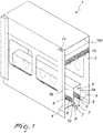
- a fan assembly for cleanrooms 2 is globally indicated by 1.
- assembly 1 comprises an inlet unit 100, arranged in the upper wall 2b of the chamber 2, of a laminar stream of gas directed towards a transport line, and suction members (not shown in the drawings) of the air for extracting the gas from chamber 2.
- the chamber 2 is defined by a floor 4, two opposing side walls 2a and by an upper wall 2b.
- the assembly 1 comprises at least one conveying channel 3 for the gas and for liquid substances present in the chamber 2 defined, preferably in a substantially central position, on the floor 4 of the chamber 2 at the transport line.
- This arrangement is extremely advantageous as it ensures that the laminar stream of gas can circulate inside the chamber 2 without microturbulences being created, thereby allowing expulsion from the chamber 2 of the particles and/or contaminants in suspension in the air that could accumulate inside the chamber 2 and the components contained therein.
- the conveyance channel 3 can be provided with a discharge outlet 7 for the liquid substances present inside the chamber 2.
- washing and sanitising fluids will then be conveyed towards the channel 3 to be in turn expelled outside of the chamber 2 through the outlet 7.
- the channel 3 can comprise a lower longitudinal discharge duct 9 for collecting the liquid substances; the discharge outlet 7 can then be placed in the lower portion of this longitudinal discharge duct 9.
- conveyance channel 3 comprising a passage 10 for a respective connecting duct 11 to the suction members, is not excluded.
- This passage 10 may be defined on a side wall of the channel 3.
- the presence of the discharge duct 9 therefore allows the liquid substances to be conveyed at a lower height with respect to that of passage 10, thus the possibility of the liquid substances being expelled through the air suction unit is further prevented.
- the liquid substances will tend, due to gravity, to accumulate on the bottom of the conveying duct 3 and, in particular, in the longitudinal discharge duct 9.
- said duct 11 having a first portion arranged below the flooring 4 of the chamber 2 and a second portion along the side wall 2a of the chamber 2 itself.
- the longitudinal discharge duct 9 may have a slope towards the outlet 7.
- the inlet unit 100 of a laminar stream of gas comprises a fan compressor 14, a pipe 15 connected downstream of the compressor 14, and a plurality of dispensing nozzles 12 surmounting the conveyance line.
- the nozzles are arranged on the upper wall 2b of the chamber 2.
- the gas introduced by the inlet apparatus will be air, preventively filtered through a suitable filter 13.
- the filter 13 is interposed between the inlet unit 100 and the chamber 2 to filter the gas introduced by the inlet unit 100 before it reaches the chamber 2.
- gas such as for example inert gases, nitrogen and the like according to the specific application needs, is not excluded.
- the present invention solves the aforementioned problems, by proposing a fan assembly 1 for cleanrooms 2, suitable for allowing expulsion of the gases outside the chamber 2, thus keeping the concentration of airborne particles within the predefined limits.
- the fan assembly 1 for cleanrooms 2 prevents microturbulences from being created in the stream of air that circulates inside the chamber 2 allowing an efficient elimination of the particles.
Landscapes
- Engineering & Computer Science (AREA)
- Chemical & Material Sciences (AREA)
- Combustion & Propulsion (AREA)
- Mechanical Engineering (AREA)
- General Engineering & Computer Science (AREA)
- Filtering Of Dispersed Particles In Gases (AREA)
- Ventilation (AREA)
- Duct Arrangements (AREA)
- Bidet-Like Cleaning Device And Other Flush Toilet Accessories (AREA)
Claims (13)
- Lüfteranordnung für Reinräume, umfassend: eine Kammer (2), die durch einen Boden (4), zwei gegenüberliegende Seitenwände (2a) und eine obere Wand (2b) definiert ist; eine Einlasseinheit (100), die an den oberen Wänden (2b) der genannten Kammer (2), zum Einleiten eines laminaren Gasstroms in die zum Boden (4) gerichtete Kammer (2), positioniert ist, wobei die Kammer (2) derart angeordnet ist, dass sie von dem von der Einlasseinheit (100) eingebrachten Gas intern belagert wird, wobei die Anordnung ferner einen Förderkanal (3) für das Gas und für flüssige Substanzen, die in der auf dem Boden (4) positionierten Kammer (2) vorhanden sind, umfasst,
wobei der Förderkanal (3) von einem Gehäuse (5), das durch eine obere Wand (5b) und zwei gegenüberliegende Seitenwände (5a) definiert ist, überragt ist, und dadurch gekennzeichnet ist, dass jede Seitenwand (5a) des Gehäuses (5) mit Durchgangsöffnungen (6), die die Kammer (2) in Verbindung mit dem Förderkanal (3) bringen, versehen ist, und dass die gegenüberliegenden Seitenwände (5a) des Gehäuses (5) in einem Abstand von den jeweiligen gegenüberliegenden Seitenwänden (2a) der Kammer (2) angeordnet sind. - Lüfteranordnung nach Anspruch 1, wobei die gegenüberliegenden Seitenwände (5a) des Gehäuses (5) parallel zueinander sind.
- Lüfteranordnung nach Anspruch 1 oder 2, wobei das Gehäuse (5) in einer zentralen Position auf dem Boden (4) der Kammer (2) angeordnet ist.
- Lüfteranordnung nach einem der vorhergehenden Ansprüche, wobei der Förderkanal (3) mit einem Auslass (7) für in der Kammer (2) vorhandene flüssige Substanzen versehen ist.
- Lüfteranordnung nach einem der vorhergehenden Ansprüche, wobei der Boden (4) von jeder Seitenwand (2a) der Kammer (2) zum Förderkanal (3) geneigt ist.
- Lüfteranordnung nach einem der vorhergehenden Ansprüche, ferner umfassend Luftansaugelemente zum Absaugen des Gases aus dem Gehäuse (5).
- Lüfteranordnung nach einem der vorhergehenden Ansprüche, wobei das Gehäuse (5) mindestens ein Gitter (8) an den Öffnungen (6) umfasst, das geeignet ist, den Durchgang des Gases zu ermöglichen und den Durchgang von Fremdkörpern zu verhindern.
- Lüfteranordnung nach einem der vorhergehenden Ansprüche 4 bis 7, wobei der Kanal (3) einen Längsauslasskanal (9) zum Sammeln der flüssigen Substanzen umfasst.
- Lüfteranordnung nach Anspruch 8, wobei der Auslass (7) in dem unteren Abschnitt des Längsauslasskanals (9) positioniert ist.
- Lüfteranordnung nach einem der vorhergehenden Ansprüche 6 bis 9, wobei der Förderkanal (3) einen Durchgang (10) für einen Verbindungskanal (11) zu den Saugelementen umfasst, wobei der Durchgang (10) an einer Seitenwand des Kanals (3) positioniert ist.
- Lüfteranordnung nach einem der vorhergehenden Ansprüche 8 bis 10, wobei der Längsauslasskanal (9) eine Neigung zum Auslass (7) aufweist, um das Ausströmen der flüssigen Substanzen durch den Auslass (7) zu erleichtern.
- Lüfteranordnung nach einem der vorhergehenden Ansprüche, wobei die Einlasseinheit (100) eines laminaren Gasstroms einen Lüfterkompressor (14), ein Rohr (15), das stromabwärts des Kompressors (14) angeschlossen ist, und mehrere Abgabedüsen (12), die an der oberen Wand (2b) der Kammer (2) positioniert sind, umfasst.
- Lüfteranordnung nach einem der vorhergehenden Ansprüche, umfassend einen Filter (13), der zwischen der Einlasseinheit (100) und der Kammer (2) angeordnet ist, um das von der Einlasseinheit (100) eingebrachte Gas zu filtern.
Applications Claiming Priority (2)
| Application Number | Priority Date | Filing Date | Title |
|---|---|---|---|
| IT102016000078030A IT201600078030A1 (it) | 2016-07-26 | 2016-07-26 | Gruppo di ventilazione per camere a contaminazione controllata |
| PCT/EP2017/068652 WO2018019771A1 (en) | 2016-07-26 | 2017-07-24 | Fan assembly for cleanrooms |
Publications (2)
| Publication Number | Publication Date |
|---|---|
| EP3491299A1 EP3491299A1 (de) | 2019-06-05 |
| EP3491299B1 true EP3491299B1 (de) | 2020-07-15 |
Family
ID=57610160
Family Applications (1)
| Application Number | Title | Priority Date | Filing Date |
|---|---|---|---|
| EP17740417.5A Active EP3491299B1 (de) | 2016-07-26 | 2017-07-24 | Gebläseanordnung für reinräume |
Country Status (7)
| Country | Link |
|---|---|
| US (1) | US11608999B2 (de) |
| EP (1) | EP3491299B1 (de) |
| JP (1) | JP6992048B2 (de) |
| CN (1) | CN109790987B (de) |
| ES (1) | ES2818649T3 (de) |
| IT (1) | IT201600078030A1 (de) |
| WO (1) | WO2018019771A1 (de) |
Family Cites Families (15)
| Publication number | Priority date | Publication date | Assignee | Title |
|---|---|---|---|---|
| CH522859A (de) * | 1970-04-28 | 1972-05-15 | Allo Pro Ag | Kammer für die Ausführung chirurgischer Eingriffe |
| JPS62138637A (ja) * | 1985-12-12 | 1987-06-22 | Matsushita Seiko Co Ltd | クリ−ンル−ム制御装置 |
| US4832717A (en) * | 1988-05-10 | 1989-05-23 | Nu Aire, Inc. | Clean air cabinet |
| DE69228014T2 (de) * | 1991-01-29 | 1999-05-27 | Shinko Electric Co., Ltd., Tokio/Tokyo | Einheit zum luftdichten Aufbewahren von Halbleiterscheiben |
| DE19619495A1 (de) * | 1996-05-14 | 1997-11-20 | Mrd Medical Research And Dev P | Sicherheitssystem mit Absaugeinrichtungen |
| JP2001054739A (ja) | 1999-08-19 | 2001-02-27 | Shibuya Kogyo Co Ltd | アイソレータ |
| US6272767B1 (en) * | 1999-10-21 | 2001-08-14 | Envirotronics, Inc. | Environmental test chamber |
| JP2002045709A (ja) * | 2000-08-08 | 2002-02-12 | Yoshihisa Hayakawa | 液貯溜タンク付きフード |
| DE10214158B4 (de) * | 2002-03-28 | 2008-04-10 | Thermo Electron Led Gmbh | Bodenwanne für eine Sicherheitswerkbank und Verfahren zu deren Herstellung |
| KR20050062366A (ko) * | 2003-12-18 | 2005-06-23 | 엠 플러스 더블유 짠더 퍼실리티 엔지니어링 게엠베하 | 순환공기, 특히 청정공기의 공조장치 |
| US7074123B2 (en) * | 2004-01-13 | 2006-07-11 | Power Of 4, L.L.C. | Cabinet for computer devices with air distribution device |
| JP6434248B2 (ja) * | 2014-08-01 | 2018-12-05 | 日本エアーテック株式会社 | 安全キャビネット |
| JP4863850B2 (ja) * | 2006-11-24 | 2012-01-25 | 三機工業株式会社 | クリーンルーム装置 |
| TWM326441U (en) * | 2007-06-01 | 2008-02-01 | Inst Of Occupational Safety & Health Council Of Labor Affairs | Biological safety cabinet with air curtain |
| JP5689255B2 (ja) | 2010-06-18 | 2015-03-25 | 株式会社エアレックス | 空気清浄用フィルタユニット及びアイソレーター装置 |
-
2016
- 2016-07-26 IT IT102016000078030A patent/IT201600078030A1/it unknown
-
2017
- 2017-07-24 CN CN201780058823.1A patent/CN109790987B/zh active Active
- 2017-07-24 ES ES17740417T patent/ES2818649T3/es active Active
- 2017-07-24 JP JP2019504971A patent/JP6992048B2/ja active Active
- 2017-07-24 WO PCT/EP2017/068652 patent/WO2018019771A1/en not_active Ceased
- 2017-07-24 EP EP17740417.5A patent/EP3491299B1/de active Active
- 2017-07-24 US US16/321,428 patent/US11608999B2/en active Active
Non-Patent Citations (1)
| Title |
|---|
| None * |
Also Published As
| Publication number | Publication date |
|---|---|
| ES2818649T3 (es) | 2021-04-13 |
| JP6992048B2 (ja) | 2022-02-03 |
| IT201600078030A1 (it) | 2018-01-26 |
| JP2019525117A (ja) | 2019-09-05 |
| EP3491299A1 (de) | 2019-06-05 |
| CN109790987A (zh) | 2019-05-21 |
| WO2018019771A1 (en) | 2018-02-01 |
| CA3032013A1 (en) | 2018-02-01 |
| US11608999B2 (en) | 2023-03-21 |
| US20210285667A1 (en) | 2021-09-16 |
| CN109790987B (zh) | 2021-02-26 |
Similar Documents
| Publication | Publication Date | Title |
|---|---|---|
| US11577950B2 (en) | Device for treating containers | |
| KR101601246B1 (ko) | 공기 정화장치 | |
| KR20150057379A (ko) | 기판 세정 장치 | |
| KR101832853B1 (ko) | 도장공정용 페인트유해물질 제거장치 | |
| KR101475866B1 (ko) | 백필터 집진장치 | |
| KR101216049B1 (ko) | 이젝터 집진 시스템 | |
| EP3491299B1 (de) | Gebläseanordnung für reinräume | |
| KR20160034154A (ko) | 도색 분진 처리장치 | |
| KR101808383B1 (ko) | 분진처리장치 | |
| KR101592390B1 (ko) | 하역차량용 건식 세륜기 | |
| CA3032013C (en) | Fan assembly for cleanrooms | |
| KR20160142469A (ko) | 재생형 필터 자동 세척장치 | |
| US10173160B2 (en) | Effluent removal system and method of use | |
| KR100826827B1 (ko) | 제습 클린 부스 | |
| KR20220058070A (ko) | 자동 수위조절 장치를 겸비한 탈취시스템 | |
| KR102093481B1 (ko) | 악취 저감 시스템 및 이를 위한 스크러버 | |
| EP1475138A1 (de) | Filterapparatur für Fluide mit partikelförmigen Abfallstoffen | |
| US20090249744A1 (en) | Packing machine | |
| JP4479000B2 (ja) | 清浄空気供給装置 | |
| NL2012844B1 (nl) | Modulaire filtertoren. | |
| TW201822870A (zh) | 濕式集塵機 | |
| KR101601250B1 (ko) | 공기 정화장치 | |
| KR100500428B1 (ko) | 에어 샤워 장치 | |
| CN117377535A (zh) | 具有过喷物去除系统的涂装设备 | |
| KR200383344Y1 (ko) | 에어 샤워 장치 |
Legal Events
| Date | Code | Title | Description |
|---|---|---|---|
| STAA | Information on the status of an ep patent application or granted ep patent |
Free format text: STATUS: UNKNOWN |
|
| STAA | Information on the status of an ep patent application or granted ep patent |
Free format text: STATUS: THE INTERNATIONAL PUBLICATION HAS BEEN MADE |
|
| PUAI | Public reference made under article 153(3) epc to a published international application that has entered the european phase |
Free format text: ORIGINAL CODE: 0009012 |
|
| STAA | Information on the status of an ep patent application or granted ep patent |
Free format text: STATUS: REQUEST FOR EXAMINATION WAS MADE |
|
| 17P | Request for examination filed |
Effective date: 20190226 |
|
| AK | Designated contracting states |
Kind code of ref document: A1 Designated state(s): AL AT BE BG CH CY CZ DE DK EE ES FI FR GB GR HR HU IE IS IT LI LT LU LV MC MK MT NL NO PL PT RO RS SE SI SK SM TR |
|
| AX | Request for extension of the european patent |
Extension state: BA ME |
|
| DAV | Request for validation of the european patent (deleted) | ||
| DAX | Request for extension of the european patent (deleted) | ||
| GRAP | Despatch of communication of intention to grant a patent |
Free format text: ORIGINAL CODE: EPIDOSNIGR1 |
|
| STAA | Information on the status of an ep patent application or granted ep patent |
Free format text: STATUS: GRANT OF PATENT IS INTENDED |
|
| INTG | Intention to grant announced |
Effective date: 20200402 |
|
| GRAS | Grant fee paid |
Free format text: ORIGINAL CODE: EPIDOSNIGR3 |
|
| GRAA | (expected) grant |
Free format text: ORIGINAL CODE: 0009210 |
|
| STAA | Information on the status of an ep patent application or granted ep patent |
Free format text: STATUS: THE PATENT HAS BEEN GRANTED |
|
| AK | Designated contracting states |
Kind code of ref document: B1 Designated state(s): AL AT BE BG CH CY CZ DE DK EE ES FI FR GB GR HR HU IE IS IT LI LT LU LV MC MK MT NL NO PL PT RO RS SE SI SK SM TR |
|
| REG | Reference to a national code |
Ref country code: CH Ref legal event code: EP Ref country code: GB Ref legal event code: FG4D |
|
| REG | Reference to a national code |
Ref country code: IE Ref legal event code: FG4D |
|
| REG | Reference to a national code |
Ref country code: DE Ref legal event code: R096 Ref document number: 602017019860 Country of ref document: DE |
|
| REG | Reference to a national code |
Ref country code: AT Ref legal event code: REF Ref document number: 1291471 Country of ref document: AT Kind code of ref document: T Effective date: 20200815 |
|
| REG | Reference to a national code |
Ref country code: LT Ref legal event code: MG4D |
|
| REG | Reference to a national code |
Ref country code: DE Ref legal event code: R079 Ref document number: 602017019860 Country of ref document: DE Free format text: PREVIOUS MAIN CLASS: F24F0003160000 Ipc: F24F0008000000 |
|
| REG | Reference to a national code |
Ref country code: AT Ref legal event code: MK05 Ref document number: 1291471 Country of ref document: AT Kind code of ref document: T Effective date: 20200715 |
|
| REG | Reference to a national code |
Ref country code: NL Ref legal event code: MP Effective date: 20200715 |
|
| PG25 | Lapsed in a contracting state [announced via postgrant information from national office to epo] |
Ref country code: FI Free format text: LAPSE BECAUSE OF FAILURE TO SUBMIT A TRANSLATION OF THE DESCRIPTION OR TO PAY THE FEE WITHIN THE PRESCRIBED TIME-LIMIT Effective date: 20200715 Ref country code: SE Free format text: LAPSE BECAUSE OF FAILURE TO SUBMIT A TRANSLATION OF THE DESCRIPTION OR TO PAY THE FEE WITHIN THE PRESCRIBED TIME-LIMIT Effective date: 20200715 Ref country code: HR Free format text: LAPSE BECAUSE OF FAILURE TO SUBMIT A TRANSLATION OF THE DESCRIPTION OR TO PAY THE FEE WITHIN THE PRESCRIBED TIME-LIMIT Effective date: 20200715 Ref country code: LT Free format text: LAPSE BECAUSE OF FAILURE TO SUBMIT A TRANSLATION OF THE DESCRIPTION OR TO PAY THE FEE WITHIN THE PRESCRIBED TIME-LIMIT Effective date: 20200715 Ref country code: PT Free format text: LAPSE BECAUSE OF FAILURE TO SUBMIT A TRANSLATION OF THE DESCRIPTION OR TO PAY THE FEE WITHIN THE PRESCRIBED TIME-LIMIT Effective date: 20201116 Ref country code: GR Free format text: LAPSE BECAUSE OF FAILURE TO SUBMIT A TRANSLATION OF THE DESCRIPTION OR TO PAY THE FEE WITHIN THE PRESCRIBED TIME-LIMIT Effective date: 20201016 Ref country code: NO Free format text: LAPSE BECAUSE OF FAILURE TO SUBMIT A TRANSLATION OF THE DESCRIPTION OR TO PAY THE FEE WITHIN THE PRESCRIBED TIME-LIMIT Effective date: 20201015 Ref country code: AT Free format text: LAPSE BECAUSE OF FAILURE TO SUBMIT A TRANSLATION OF THE DESCRIPTION OR TO PAY THE FEE WITHIN THE PRESCRIBED TIME-LIMIT Effective date: 20200715 Ref country code: BG Free format text: LAPSE BECAUSE OF FAILURE TO SUBMIT A TRANSLATION OF THE DESCRIPTION OR TO PAY THE FEE WITHIN THE PRESCRIBED TIME-LIMIT Effective date: 20201015 |
|
| PG25 | Lapsed in a contracting state [announced via postgrant information from national office to epo] |
Ref country code: LV Free format text: LAPSE BECAUSE OF FAILURE TO SUBMIT A TRANSLATION OF THE DESCRIPTION OR TO PAY THE FEE WITHIN THE PRESCRIBED TIME-LIMIT Effective date: 20200715 Ref country code: RS Free format text: LAPSE BECAUSE OF FAILURE TO SUBMIT A TRANSLATION OF THE DESCRIPTION OR TO PAY THE FEE WITHIN THE PRESCRIBED TIME-LIMIT Effective date: 20200715 Ref country code: PL Free format text: LAPSE BECAUSE OF FAILURE TO SUBMIT A TRANSLATION OF THE DESCRIPTION OR TO PAY THE FEE WITHIN THE PRESCRIBED TIME-LIMIT Effective date: 20200715 Ref country code: IS Free format text: LAPSE BECAUSE OF FAILURE TO SUBMIT A TRANSLATION OF THE DESCRIPTION OR TO PAY THE FEE WITHIN THE PRESCRIBED TIME-LIMIT Effective date: 20201115 |
|
| REG | Reference to a national code |
Ref country code: CH Ref legal event code: PL |
|
| PG25 | Lapsed in a contracting state [announced via postgrant information from national office to epo] |
Ref country code: NL Free format text: LAPSE BECAUSE OF FAILURE TO SUBMIT A TRANSLATION OF THE DESCRIPTION OR TO PAY THE FEE WITHIN THE PRESCRIBED TIME-LIMIT Effective date: 20200715 |
|
| REG | Reference to a national code |
Ref country code: ES Ref legal event code: FG2A Ref document number: 2818649 Country of ref document: ES Kind code of ref document: T3 Effective date: 20210413 |
|
| REG | Reference to a national code |
Ref country code: DE Ref legal event code: R097 Ref document number: 602017019860 Country of ref document: DE |
|
| REG | Reference to a national code |
Ref country code: BE Ref legal event code: MM Effective date: 20200731 |
|
| PG25 | Lapsed in a contracting state [announced via postgrant information from national office to epo] |
Ref country code: LI Free format text: LAPSE BECAUSE OF NON-PAYMENT OF DUE FEES Effective date: 20200731 Ref country code: LU Free format text: LAPSE BECAUSE OF NON-PAYMENT OF DUE FEES Effective date: 20200724 Ref country code: CZ Free format text: LAPSE BECAUSE OF FAILURE TO SUBMIT A TRANSLATION OF THE DESCRIPTION OR TO PAY THE FEE WITHIN THE PRESCRIBED TIME-LIMIT Effective date: 20200715 Ref country code: DK Free format text: LAPSE BECAUSE OF FAILURE TO SUBMIT A TRANSLATION OF THE DESCRIPTION OR TO PAY THE FEE WITHIN THE PRESCRIBED TIME-LIMIT Effective date: 20200715 Ref country code: CH Free format text: LAPSE BECAUSE OF NON-PAYMENT OF DUE FEES Effective date: 20200731 Ref country code: RO Free format text: LAPSE BECAUSE OF FAILURE TO SUBMIT A TRANSLATION OF THE DESCRIPTION OR TO PAY THE FEE WITHIN THE PRESCRIBED TIME-LIMIT Effective date: 20200715 Ref country code: SM Free format text: LAPSE BECAUSE OF FAILURE TO SUBMIT A TRANSLATION OF THE DESCRIPTION OR TO PAY THE FEE WITHIN THE PRESCRIBED TIME-LIMIT Effective date: 20200715 Ref country code: EE Free format text: LAPSE BECAUSE OF FAILURE TO SUBMIT A TRANSLATION OF THE DESCRIPTION OR TO PAY THE FEE WITHIN THE PRESCRIBED TIME-LIMIT Effective date: 20200715 |
|
| PLBE | No opposition filed within time limit |
Free format text: ORIGINAL CODE: 0009261 |
|
| STAA | Information on the status of an ep patent application or granted ep patent |
Free format text: STATUS: NO OPPOSITION FILED WITHIN TIME LIMIT |
|
| PG25 | Lapsed in a contracting state [announced via postgrant information from national office to epo] |
Ref country code: BE Free format text: LAPSE BECAUSE OF NON-PAYMENT OF DUE FEES Effective date: 20200731 Ref country code: AL Free format text: LAPSE BECAUSE OF FAILURE TO SUBMIT A TRANSLATION OF THE DESCRIPTION OR TO PAY THE FEE WITHIN THE PRESCRIBED TIME-LIMIT Effective date: 20200715 |
|
| 26N | No opposition filed |
Effective date: 20210416 |
|
| PG25 | Lapsed in a contracting state [announced via postgrant information from national office to epo] |
Ref country code: SK Free format text: LAPSE BECAUSE OF FAILURE TO SUBMIT A TRANSLATION OF THE DESCRIPTION OR TO PAY THE FEE WITHIN THE PRESCRIBED TIME-LIMIT Effective date: 20200715 |
|
| PG25 | Lapsed in a contracting state [announced via postgrant information from national office to epo] |
Ref country code: SI Free format text: LAPSE BECAUSE OF FAILURE TO SUBMIT A TRANSLATION OF THE DESCRIPTION OR TO PAY THE FEE WITHIN THE PRESCRIBED TIME-LIMIT Effective date: 20200715 Ref country code: IE Free format text: LAPSE BECAUSE OF NON-PAYMENT OF DUE FEES Effective date: 20200724 |
|
| PG25 | Lapsed in a contracting state [announced via postgrant information from national office to epo] |
Ref country code: TR Free format text: LAPSE BECAUSE OF FAILURE TO SUBMIT A TRANSLATION OF THE DESCRIPTION OR TO PAY THE FEE WITHIN THE PRESCRIBED TIME-LIMIT Effective date: 20200715 Ref country code: MT Free format text: LAPSE BECAUSE OF FAILURE TO SUBMIT A TRANSLATION OF THE DESCRIPTION OR TO PAY THE FEE WITHIN THE PRESCRIBED TIME-LIMIT Effective date: 20200715 Ref country code: CY Free format text: LAPSE BECAUSE OF FAILURE TO SUBMIT A TRANSLATION OF THE DESCRIPTION OR TO PAY THE FEE WITHIN THE PRESCRIBED TIME-LIMIT Effective date: 20200715 |
|
| PG25 | Lapsed in a contracting state [announced via postgrant information from national office to epo] |
Ref country code: MK Free format text: LAPSE BECAUSE OF FAILURE TO SUBMIT A TRANSLATION OF THE DESCRIPTION OR TO PAY THE FEE WITHIN THE PRESCRIBED TIME-LIMIT Effective date: 20200715 Ref country code: MC Free format text: LAPSE BECAUSE OF FAILURE TO SUBMIT A TRANSLATION OF THE DESCRIPTION OR TO PAY THE FEE WITHIN THE PRESCRIBED TIME-LIMIT Effective date: 20200715 |
|
| P01 | Opt-out of the competence of the unified patent court (upc) registered |
Effective date: 20230426 |
|
| PGFP | Annual fee paid to national office [announced via postgrant information from national office to epo] |
Ref country code: ES Payment date: 20250827 Year of fee payment: 9 |
|
| PGFP | Annual fee paid to national office [announced via postgrant information from national office to epo] |
Ref country code: DE Payment date: 20250723 Year of fee payment: 9 |
|
| PGFP | Annual fee paid to national office [announced via postgrant information from national office to epo] |
Ref country code: IT Payment date: 20250722 Year of fee payment: 9 |
|
| PGFP | Annual fee paid to national office [announced via postgrant information from national office to epo] |
Ref country code: GB Payment date: 20250724 Year of fee payment: 9 |
|
| PGFP | Annual fee paid to national office [announced via postgrant information from national office to epo] |
Ref country code: FR Payment date: 20250717 Year of fee payment: 9 |