EP3491908A1 - Moissonneuse et/ou machine de traitement du sol agricole - Google Patents
Moissonneuse et/ou machine de traitement du sol agricole Download PDFInfo
- Publication number
- EP3491908A1 EP3491908A1 EP18210080.0A EP18210080A EP3491908A1 EP 3491908 A1 EP3491908 A1 EP 3491908A1 EP 18210080 A EP18210080 A EP 18210080A EP 3491908 A1 EP3491908 A1 EP 3491908A1
- Authority
- EP
- European Patent Office
- Prior art keywords
- pressure medium
- pressure
- actuators
- axle
- medium actuators
- Prior art date
- Legal status (The legal status is an assumption and is not a legal conclusion. Google has not performed a legal analysis and makes no representation as to the accuracy of the status listed.)
- Granted
Links
Images


Classifications
-
- A—HUMAN NECESSITIES
- A01—AGRICULTURE; FORESTRY; ANIMAL HUSBANDRY; HUNTING; TRAPPING; FISHING
- A01D—HARVESTING; MOWING
- A01D75/00—Accessories for harvesters or mowers
- A01D75/28—Control mechanisms for harvesters or mowers when moving on slopes; Devices preventing lateral pull
-
- A—HUMAN NECESSITIES
- A01—AGRICULTURE; FORESTRY; ANIMAL HUSBANDRY; HUNTING; TRAPPING; FISHING
- A01F—PROCESSING OF HARVESTED PRODUCE; HAY OR STRAW PRESSES; DEVICES FOR STORING AGRICULTURAL OR HORTICULTURAL PRODUCE
- A01F15/00—Baling presses for straw, hay or the like
- A01F15/08—Details
-
- B—PERFORMING OPERATIONS; TRANSPORTING
- B60—VEHICLES IN GENERAL
- B60G—VEHICLE SUSPENSION ARRANGEMENTS
- B60G21/00—Interconnection systems for two or more resiliently-suspended wheels, e.g. for stabilising a vehicle body with respect to acceleration, deceleration or centrifugal forces
- B60G21/002—Interconnection systems for two or more resiliently-suspended wheels, e.g. for stabilising a vehicle body with respect to acceleration, deceleration or centrifugal forces longitudinally
-
- B—PERFORMING OPERATIONS; TRANSPORTING
- B60—VEHICLES IN GENERAL
- B60G—VEHICLE SUSPENSION ARRANGEMENTS
- B60G21/00—Interconnection systems for two or more resiliently-suspended wheels, e.g. for stabilising a vehicle body with respect to acceleration, deceleration or centrifugal forces
- B60G21/02—Interconnection systems for two or more resiliently-suspended wheels, e.g. for stabilising a vehicle body with respect to acceleration, deceleration or centrifugal forces permanently interconnected
- B60G21/023—Interconnection systems for two or more resiliently-suspended wheels, e.g. for stabilising a vehicle body with respect to acceleration, deceleration or centrifugal forces permanently interconnected longitudinally
-
- B—PERFORMING OPERATIONS; TRANSPORTING
- B60—VEHICLES IN GENERAL
- B60G—VEHICLE SUSPENSION ARRANGEMENTS
- B60G21/00—Interconnection systems for two or more resiliently-suspended wheels, e.g. for stabilising a vehicle body with respect to acceleration, deceleration or centrifugal forces
- B60G21/02—Interconnection systems for two or more resiliently-suspended wheels, e.g. for stabilising a vehicle body with respect to acceleration, deceleration or centrifugal forces permanently interconnected
- B60G21/06—Interconnection systems for two or more resiliently-suspended wheels, e.g. for stabilising a vehicle body with respect to acceleration, deceleration or centrifugal forces permanently interconnected fluid
- B60G21/067—Interconnection systems for two or more resiliently-suspended wheels, e.g. for stabilising a vehicle body with respect to acceleration, deceleration or centrifugal forces permanently interconnected fluid between wheels on different axles on the same side of the vehicle, i.e. the left or the right side
-
- B—PERFORMING OPERATIONS; TRANSPORTING
- B60—VEHICLES IN GENERAL
- B60G—VEHICLE SUSPENSION ARRANGEMENTS
- B60G5/00—Resilient suspensions for a set of tandem wheels or axles having interrelated movements
- B60G5/04—Resilient suspensions for a set of tandem wheels or axles having interrelated movements with two or more pivoted arms, the movements of which are resiliently interrelated, e.g. the arms being rigid
- B60G5/06—Resilient suspensions for a set of tandem wheels or axles having interrelated movements with two or more pivoted arms, the movements of which are resiliently interrelated, e.g. the arms being rigid the arms turning on a common pivot, e.g. being rigid
-
- A—HUMAN NECESSITIES
- A01—AGRICULTURE; FORESTRY; ANIMAL HUSBANDRY; HUNTING; TRAPPING; FISHING
- A01F—PROCESSING OF HARVESTED PRODUCE; HAY OR STRAW PRESSES; DEVICES FOR STORING AGRICULTURAL OR HORTICULTURAL PRODUCE
- A01F15/00—Baling presses for straw, hay or the like
- A01F15/07—Rotobalers, i.e. machines for forming cylindrical bales by winding and pressing
- A01F15/071—Wrapping devices
- A01F2015/0735—Combined machines that include a press bale and a wrapping device in a further step, e.g. turning table, not in the same closed pressing chamber
-
- B—PERFORMING OPERATIONS; TRANSPORTING
- B60—VEHICLES IN GENERAL
- B60G—VEHICLE SUSPENSION ARRANGEMENTS
- B60G2200/00—Indexing codes relating to suspension types
- B60G2200/30—Rigid axle suspensions
- B60G2200/318—Rigid axle suspensions two or more axles being mounted on a longitudinal rocking or walking beam
-
- B—PERFORMING OPERATIONS; TRANSPORTING
- B60—VEHICLES IN GENERAL
- B60G—VEHICLE SUSPENSION ARRANGEMENTS
- B60G2204/00—Indexing codes related to suspensions per se or to auxiliary parts
- B60G2204/80—Interactive suspensions; arrangement affecting more than one suspension unit
- B60G2204/81—Interactive suspensions; arrangement affecting more than one suspension unit front and rear unit
-
- B—PERFORMING OPERATIONS; TRANSPORTING
- B60—VEHICLES IN GENERAL
- B60G—VEHICLE SUSPENSION ARRANGEMENTS
- B60G2204/00—Indexing codes related to suspensions per se or to auxiliary parts
- B60G2204/80—Interactive suspensions; arrangement affecting more than one suspension unit
- B60G2204/83—Type of interconnection
- B60G2204/8304—Type of interconnection using a fluid
-
- B—PERFORMING OPERATIONS; TRANSPORTING
- B60—VEHICLES IN GENERAL
- B60G—VEHICLE SUSPENSION ARRANGEMENTS
- B60G2206/00—Indexing codes related to the manufacturing of suspensions: constructional features, the materials used, procedures or tools
- B60G2206/01—Constructional features of suspension elements, e.g. arms, dampers, springs
- B60G2206/011—Modular constructions
- B60G2206/0112—Bogies for heavy vehicles
-
- B—PERFORMING OPERATIONS; TRANSPORTING
- B60—VEHICLES IN GENERAL
- B60G—VEHICLE SUSPENSION ARRANGEMENTS
- B60G2300/00—Indexing codes relating to the type of vehicle
- B60G2300/04—Trailers
-
- B—PERFORMING OPERATIONS; TRANSPORTING
- B60—VEHICLES IN GENERAL
- B60G—VEHICLE SUSPENSION ARRANGEMENTS
- B60G2300/00—Indexing codes relating to the type of vehicle
- B60G2300/04—Trailers
- B60G2300/042—Semi-trailers
-
- B—PERFORMING OPERATIONS; TRANSPORTING
- B60—VEHICLES IN GENERAL
- B60G—VEHICLE SUSPENSION ARRANGEMENTS
- B60G2300/00—Indexing codes relating to the type of vehicle
- B60G2300/08—Agricultural vehicles
-
- B—PERFORMING OPERATIONS; TRANSPORTING
- B60—VEHICLES IN GENERAL
- B60G—VEHICLE SUSPENSION ARRANGEMENTS
- B60G2500/00—Indexing codes relating to the regulated action or device
- B60G2500/30—Height or ground clearance
Definitions
- the present invention relates to an agricultural harvesting and / or tillage machine with a machine frame, which is supported by at least one bogey landing gear on the ground, which has two each attached to an axle carrier axles, which together with the wheel axles in the manner of a rocker about a pivot axis is pivotally mounted, wherein the axle carrier for height adjustment of the bogey chassis is divided into at least two axle carrier parts, which are pivotable relative to each other.
- Agricultural harvesting and / or tillage machines such as balers or self-loading wagons with a pick-up device for picking up crops from the ground are often equipped with bogey landing gear, since such bogey landing gear enables a favorable ground leveling with uniform load distribution on both axles and wavy terrain another allows a height adjustment of the chassis in a simple manner.
- the height adjustment on the left and right lanes can also be done independently or individually, so that in a simple way a leveling can be achieved, that is, when driving parallel on a slope across the slope, the lower bogey suspension higher and / or uphill suspension lower be placed so that the machine structure is approximately horizontal or at least less inclined and a certain tilt compensation is achieved.
- this may be useful to facilitate the transfer of a finished wound bale from the pressing chamber to the winding device.
- this can be useful to achieve a uniform feed distribution when distributing the crop in the storage room, for example by turning on the scraper floor.
- bogey landing gears may also be useful on other agricultural machine types, such as seeders, tillage equipment such as plows, cultivators, harrows or tillage combinations, and haymaking machines such as rakes and tedders or other agricultural harvesting or tillage machines, especially if they are attached as attachments for cultivation a tug are formed.
- the font EP 3 069 598 A1 shows, for example, a baler, the machine frame is supported with a bogey landing gear on the ground, the rocker-like axle, on which the two axles are mounted, is divided and has two mutually pivotable legs to Multenverstellen the bogey chassis can.
- the two legs of the split axle carrier are articulated to a common pivot axis and connected to each other by a Stellaktor, so that by extending or shortening the Stellaktors different angular positions of the Achschtschenkel can be adjusted to each other, so that the Bogey suspension is adjusted in height.
- such a bogey chassis can also be an obstacle or the said height adjustment may not be sufficient.
- the machine may collapse unintentionally if one of the two wheel axles has traveled over the slope edge onto the downhill slope, even though the other wheel axle would still be placed on the upper section of the slope edge.
- driving over smaller grooves or smaller transverse grooves it can also lead to a restless driving behavior with vertical impacts or vibrations on the machine structure.
- the present invention has the object to provide an improved agricultural harvesting and / or tillage machine, which avoids the disadvantages of the prior art and the latter further develops in an advantageous manner.
- the chassis supporting the machine frame on the ground to be further developed to maintain the benefits of a bogey chassis, however, to eliminate or at least mitigate its disadvantages, despite height adjustment as simple as possible construction of the chassis should be maintained with few parts.
- a Adjusting device for variably setting a fixed, predeterminable angular position of the axle carrier to provide a total of the pivot axis in order to specify a specific pivot position of the axle carrier in terms of an absolute angular position of the axle beam relative to the machine frame.
- at least two pressure medium actuators are provided for adjusting the relative position of the axle carrier parts relative to each other and for adjusting the angular position of the axle carrier relative to the pivot axis relative to the machine frame.
- the at least two pressure medium actuators are arranged and configured such that on the one hand they enable normal bogey driving with counter-rotating up and down wheel axles, but on the other hand also enable driving with, as it were, frozen pivot position of the axle carrier or locking at least one axle carrier part with respect to the pivot axis , and equally can cause a height adjustment of the bogey suspension.
- said at least two pressure medium actuators can be articulated on one hand on one of the axle support parts and on the other hand on a Schwenkachsange, opposite the bogey suspension is tiltable.
- the mentioned Schwenkachslic can for example be a rigidly connected to the machine frame chassis suspension carrier, but if necessary. But also an adjustable wheel or axle suspension, against which the axle of the bogey chassis with two Achsconce former is pivotable and can be tilted up and down.
- each of the two pressure medium actuators executes an actuating movement when the axle carrier of the bogey chassis bobs up and down in bogey driving mode.
- a pressure medium control device for driving said at least two pressure medium actuators, which provides different operating modes for the pressure medium actuators, in which the pressure medium in controlled in various ways.
- said pressure medium control device may have a rocker operating mode in which the pressure medium actuators are short-circuited to each other, so that the pressure medium actuators reciprocate pressure means according to the displacement principle or pump back and forth, if it during up and down rocking of the axle carrier to corresponding movements of Pressure medium actuators comes.
- the pressure medium cylinder can be shut off from a pressure medium source and / or from a return to the tank of the pressure medium supply, so that pressure medium is only circulated internally between the pressure medium actuators or displaced back and forth.
- said pressure medium actuators may be so shorted that upon rocking or Niederwippen an Achsangeteils the displaced from the associated Druckstoffaktor pressure fluid forces an actuating movement of the other pressure medium actuator, which leads to a counter-teetering or teetering of the other connected to the other pressure medium actuator other Achsconceteils.
- the pressure medium actuators are thus short-circuited with each other so that they force mutually actuating movements, which lead to a pivoting or tilting of the axle beam parts in the same direction of rotation.
- this can be opposite or synchronous positioning movements of the pressure actuators.
- two pressure medium cylinders are provided as pressure medium actuators, which are arranged on the same side of the axle carrier or articulated on the same side of the pivot axis on the Schwenkachslic, so that the length of one pressure medium cylinder and shorten the other pressure medium cylinder to the axle carrier Total rocking bogey-like or swing the one axle up and the other axle down, the two pressure medium cylinder can be cross-shorted together so that pressurized fluid, which is displaced during the shortening of a cylinder from this, a length of the other cylinder forces.
- the said pressure cylinder are arranged on different sides of the axle carrier or hinged on opposite sides of the pivot axis, for example in a z-like configuration or in a configuration with a cylinder above and a cylinder below the axle carrier, so that both pressure medium cylinder length to a Rocking the entire axle carrier in one direction to allow and shorten both pressure medium cylinder to allow a tilting of the axle carrier in the other direction, the pressure medium actuators can also be so shorted together that result in the same directional actuating movements.
- the pressure fluid displaced during the shortening of the one cylinder likewise forces a shortening of the other pressure medium cylinder
- the pressure fluid displaced during the length of the one pressure medium cylinder likewise forces a length of the other pressure medium cylinder
- the aforesaid pressure medium control device advantageously also has an actuating mode in which at least one of said pressure medium actuators is connected to a pressure source and / or a return, to move to a predetermined pivot position by pressurizing and / or depressurizing, and then into the predetermined position can be determined, for example by at least one pressure chamber of the pressure medium actuator is shut off by means of a check valve.
- the pressure medium control device thus provides an active setting and determining a predetermined position of the pressure medium actuator, so that the associated Achsangeteil can be determined in an absolute angular position, as said Stellaktor as above explains a pivot point on the Schwenkachslittle or an associated Anlenkteil has.
- the pressure medium control device in the said operating mode both drive and drive by connecting to the pressure source and / or the return to a predetermined absolute angular position relative to the machine frame drive and determine so that the position of both axles of the bogey suspension is adjustable and detectable.
- the said pressure medium control device may further comprise a height adjustment mode, in which the two pressure medium actuators respectively with the said pressure source, if necessary. Also with two separate pressure sources - or a return - if necessary. Also with two separate returns - are connected to the relative angular position of the two Adjust the axle carrier parts relative to each other and thus adjust the height of the bogey chassis.
- Said pressure medium control device may advantageously comprise a valve device having different switching positions in which the pressure medium actuators in the manner described above can be shorted together and optionally connected to a pressure source or a return.
- Said valve means may comprise a plurality of check valves and / or multi-way valves.
- the mentioned pressure medium actuators and their pressure medium control device are advantageously designed such that the pressure medium actuators in the mentioned short circuit or rocker mode at least approximately synchronized move, so that the controlled by the pressure medium actuators Achsskaschenkel at least approximately synchronously with each other, that is approximately the same pivot angle pivot.
- a complete synchronization of the axle support members is not necessary, but can nevertheless be provided so that the axle support legs are actually frozen rigidly in the rocker mode of operation and only to the rocking axis can rock up and down without relative movements to each other.
- the pressure medium actuators can have mutually corresponding displacement volumes, so that the forced by the displaced pressure fluid of a pressure medium actuator actuating movement of the other pressure medium actuator in terms of magnitude at least approximately the same. If the displacement volumes of the two pressure medium actuators are approximately the same size, the pressure medium actuators can be directly short-circuited with each other.
- a compensating cylinder may be provided which, if necessary, compensates for different displacement volumes or at least equates a distance to one another.
- Such a compensating cylinder may have different sized pressure chambers, wherein a larger pressure chamber in the larger pressure chamber with the pressure medium actuator larger displacement volume and the pressure chamber smaller cross-sectional area may be connected to the pressure medium actuator smaller displacement volume.
- pressure medium actuators may be shorted in the short circuit mode crosswise with each other to perform counter-rotating movements, or be short-circuited parallel to each other to perform the same direction movements.
- pressure medium cylinders can each be arranged above the axle carrier and have a pivot point on the same side of the pivot axis, so that they move in opposite directions, that is, one pressure medium cylinder length and the other pressure medium cylinder has to shorten to a bobbing Bogey operation enable.
- the said crosswise short circuit may be provided.
- the pressure medium cylinder - for example, a pressure medium cylinder above the axle carrier and a pressure medium cylinder below the axle carrier - provided, in which both pressure medium cylinder length, when the axle generally totals in one direction, and shorten both pressure medium cylinder when the axle in the other direction wobbles, said parallel short circuit can be provided to achieve a concurrent adjustment of the cylinder.
- two pressure-medium actuators can also be provided in the development of the invention.
- two further pressure medium actuators may be provided, which may be coupled in pairs with the first two pressure medium actuators, in particular connected in series, so that the actuating movement of the further pressure medium actuators is transmitted to the respective axle carriers via the first-mentioned pressure medium actuators.
- a first pressure medium actuator is coupled to a third pressure medium actuator and a second pressure medium actuator is coupled to a fourth pressure medium actuator
- the actuating movement of the third pressure medium actuator can be transmitted by the first pressure medium actuator to the associated axle carrier, while an actuating movement of the fourth pressure medium actuator via the second pressure medium actuator to the associated axle carrier is transmitted.
- the third and fourth pressure medium actuators - be provided to adjust the articulation points of the first two Druckschaktoren - ie the first and second pressure medium actuator - on the Schwenkachslic.
- the articulation points of the first and second pressure-medium actuators shift on the said pivot-axis carrier.
- the said four pressure medium actuators in pairs via transducers for example in the form of pivoting levers be coupled to each other, wherein said pivot levers each pivotable on the Schwenkachslittle can be stored.
- said pivot levers each pivotable on the Schwenkachsvice can be stored.
- a very compact design can be achieved, in which the third and fourth pressure-medium actuators can be arranged independently of the desired adjustment direction for the articulation points of the first and second pressure-medium actuators.
- a translation or reduction effect can be achieved via said pivoting lever, which allows the desired actuating movement with limited travel of the pressure medium actuators and / or limited size of the pressure medium actuators.
- the pressure-medium control device can in its rocking operating mode in itself short-circuit the first and second pressure-medium actuators as described above, wherein the third and fourth pressure-medium actuators can be shut off or locked , so that the bogey or rocking operation can be accomplished only by moving the first and second pressure cylinder.
- the pressure medium control device in the rocker operating mode can advantageously also provide for a short circuit between the pressure medium cylinders, which also includes the additional third and fourth pressure medium actuators.
- the two first-mentioned pressure-medium actuators which are articulated on the axle carrier parts, each be short-circuited with the additional pressure medium actuator with which they are not connected in series and not coupled by said transformer. If, for example, in the above-mentioned manner the first pressure medium cylinder - coupled via the pivot lever described - coupled to the third pressure medium actuator and connected in series, said first pressure fluid cylinder with the fourth pressure medium cylinder can be short-circuited, with the second pressure medium actuator - if necessary. Via another pivoting lever - is coupled.
- the said second pressure medium cylinder is then short-circuited with the aforementioned third pressure medium actuator. Accordingly, movements of the first and second pressure-medium actuators force corresponding movements of the third and fourth pressure-medium actuators, so that all four pressure-medium actuators are displaced when the overall axis member, that is to say with both axle-support parts, bobs up and down about the pivot axis during bogey-driving operation.
- the first-mentioned at least two pressure-medium actuators need not be articulated in the manner described above in each case on the one hand to a Achsconcehbib and on the other hand on the Schwenkachslittle or another machine frame fixed part.
- the two pressure medium actuators may also have separate or different functional tasks and be articulated differently.
- the one Druckschaktor be provided for the height adjustment of the bogey chassis, in particular for pivoting the two Achschtmaschine be arranged and formed relative to each other, while the other of the at least two pressure medium actuators may be provided to adjust the absolute angular position of the axle carrier relative to the machine frame and / or determine.
- one of the two pressure medium actuators may have articulation points on different axle carrier parts, so that an adjustment of the pressure medium actuator causes a pivoting of the two axle carrier parts relative to each other.
- the other of the two pressure medium actuators can be articulated on one hand on one of the two axle support parts and on the other hand have a machine frame fixed pivot point or on the previously mentioned Schwenkachslittle or an associated element, against which the axle must turn during bogey rockers, be articulated.
- each pressure medium actuator has its own task
- the pressure medium actuators can be individually adapted to their respective task and in particular also be designed differently from each other.
- the two axis parts to each other adjusting pressure medium actuator another travel and / or a have different piston diameter than the pressure medium actuator, which adjusts the angular position of the axle parts relative to the machine frame.
- the pressure medium control device for the two pressure medium actuators may be designed differently, in particular comprise different valve arrangements, by means of which the respective pressure medium actuator can be controlled.
- said pressure medium control device in its actuating mode can drive said pressure medium actuator with a machine frame fixed pivot point by pressurizing or connecting to the return to a predetermined operating position and determine, the other pressure medium actuator can remain locked with articulation points on both axle parts or also moved to another position and then it can be locked. If necessary, it would also be conceivable to switch said pressure medium actuator, which has articulation points on both axle carrier parts, into the floating position, in which case the entire weight would be absorbed by the other axle carrier part, which is locked by the pressure medium actuator with machine frame-fixed articulation point.
- the pressure control device may include a cornering mode in which one of the two wheel axles is unloaded and / or lifted while the other axle is loaded to the machine weight optionally to wear together with the support force of the drawbar.
- the pressure-medium control device can operate as a function of a curve-driving signal, wherein such a curve-driving signal can be obtained or provided in different ways.
- a curve-driving signal may be obtained or provided in different ways.
- this may be a steering angle signal of the tractor, which indicates the steering angle of the tractor.
- the deflection of the drawbar of the attachment with respect to the tractor or with respect to an attachment may be measured with a sensor and used as a Kurvenfahrsignal, depending on one of the bogey axles can be relieved and / or raised.
- such an unequal Radachsbelastung be useful in other operating situations and provided by the pressure control device.
- the attachment for example, a baler
- shocks that occur when passing the bale on the winder better intercepted and kept away from the tractor.
- the pressure control device can, for example, have a bale transfer operating mode, which distributes the load distribution in the manner mentioned Wheel axles of the bogey landing gear controls differently, wherein the pressure control device can operate in response to a bale transfer signal.
- a bale transfer signal can also be obtained or provided in various ways.
- the opening of the tailgate of the bale forming chamber can be sensed monitored and used as a transfer signal, but also the movement of the bale out of the mold chamber on the winder itself and / or a movement of a bale ejector can be monitored by sensors to signal the pressure control device that the bale transfer takes place on the winder, and to control the axle load distribution accordingly.
- the said "machine frame fixed" pivot point does not actually have to be fixed and immovable or immovable, but means only the pivot point of the pressure medium actuator, which is located on the machine frame side and is not attached to one of the axle support members. If further pressure medium actuators are provided in the above-mentioned manner, the machine frame-fixed articulation point of the first or second pressure medium actuator can lie, for example, on the said pivot lever, which is pivotably mounted on the pivot axis carrier and is coupled to the said further pressure medium actuator.
- the agricultural machine may be provided with a weighing system which detects the pressure in at least one of the pressure medium actuators of the bogey landing gear and provides a weight signal depending on the detected pressure, which characterizes the load and / or the weight of the machine.
- the pressure in the corresponding, at least one pressure medium actuator of the bogey chassis can be detected directly in a corresponding pressure chamber of the cylinder, but also in a corresponding supply line.
- said weighing system for weight determination may also detect a load on the drawbar of the machine in addition to the pressure from the bogey chassis pressure medium actuators and to take into account also the weight component which is supported by the drawbar.
- the pressure medium actuators according to the above-described function division arranged so that one of the pressure medium actuators adjusts the Achschter relative to each other and the other pressure medium actuator adjusts the absolute angular position to the machine frame, in a simple manner, only the pressure of the actuator, which controls the relative position of the Achschter for the Weighing will be recorded and used. It may be useful to switch the pressure control device of the weighing system in a weighing mode of operation in which said pressure medium actuator for the absolute angular position in floating position, so that the axle evenly distributed, and / or the pressure medium actuator for the relative position in a predetermined To move position to set a predetermined Achky geometry with predetermined lever arms for the pressure measurement.
- the pressure in both pressure medium actuators can be used, which occurs when the two pressure medium actuators are switched to floating position, i. can move in opposite directions to keep the axle in a fixed position relative to each other, but to allow a swinging of the axle beam as a whole.
- At least one of the pressure medium actuators in particular the pressure medium actuator controlling the relative position of the two axle carrier parts, can be connected to a pressure accumulator, which pressure accumulator can work as a damper to dampen shocks picked up from the ground when driving.
- a pressure accumulator By a flow connection with a pressure accumulator, the two axle support parts relative to each other perform compensating movements, if of come from the roadway shocks.
- such an accumulator may also be useful for the pressure cylinder, which dictates the absolute angular position to allow compensating movements in a corresponding manner when road shocks occur, for example, in a phase unequal axle load distribution.
- the pressure medium actuators can basically be designed in various ways.
- double cylinder can be provided, which may have two pistons on a common piston rod, which are slidably received in each separate cylinders.
- each of the cylinders may be double-acting, so that each of the two pistons can be displaced in its respective cylinder in both directions and pressurized.
- Such a double cylinder may be useful in the various arrangements of pressure medium actuators.
- the pressure medium cylinder controlling the relative movement of the two axle carrier parts and / or the pressure medium cylinder controlling the absolute angular position to the machine frame can be designed as a double cylinder in the said manner.
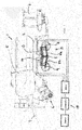
- the agricultural harvester can be designed as an attachment for attachment to a tractor, not shown, for example in the form of a baler whose machine frame 2 by means of a bogey landing gear 3 is supported on the ground.
- Fig. 1 shows only the left landing gear. However, it is understood that the harvester 1 may have such a chassis left and right.
- the machine frame 2 can be attached via a mounting device 4, for example in the form of a drawbar to the tractor, not shown, and when trained as a baler carry a bale forming chamber 5 as a machine structure.
- the two bogey trolleys 3 on the right and left sides of the machine frame 2 are designed to be height adjustable, as will be explained in more detail, wherein the trolleys 3 can advantageously be individually and independently adjustable in height to compensate for a slope can, when the harvester. 1 is moved in sloping terrain.
- both trolleys 3 can be adjusted in height to the right and left in synchronism with each other or adjusted to each other, for example, to gain more ground clearance when driving through a larger sink or driving on a ramp.
- each bogey chassis 3 comprises two axles 8.9, which are arranged in the manner of a twin axis at a short distance one behind the other and are fastened to a common axle 10, which may extend approximately lying in the direction of travel.
- the said axle 10 is pivotally mounted on a Schwenkachs phenomenon 12 about a pivot axis 11 which can extend lying transverse to the direction of travel between the axles 8 and 9, which is connected to the machine frame 2, for example, can be rigidly attached thereto.
- the named axle carrier 10 is thus tiltable up and down about a horizontal transverse axis, that is to say said pivot axis 11.
- said axle 10 is designed to be divided and comprises two axle carrier parts 10a and 10b which are pivotable relative to one another and likewise about a buckling axis extending transversely to the direction of travel.
- the two axle carrier parts 10a and 10b can be jointly pivoted on the aforementioned pivot axis 11, so that they are bendable relative to each other about the pivot axis 11 and also about the pivot axis 11 can be tilted up and down together.
- axle carrier parts 10a and 10b it would also be possible for the axle carrier parts 10a and 10b to be pivotable about two separate, parallel pivoting axles 11 and 111 and rockable up and down in the manner of a rocker, such separate pivot axles 11 and 111 advantageously being close to each other and / or approximately can be arranged centrally between the axles 8 and 9.
- At least two pressure-medium actuators 13 and 14 are provided, which may be designed in particular as a pressure medium cylinder or hydraulic cylinder.
- other training for example in the form of hydraulic rotary motors into consideration.
- the at least two pressure-medium actuators 13 and 14 can each be articulated on one of the axle carrier parts 10a or 10b and on the other hand on the pivot-axle carrier 12 or on a carrier part connected thereto or else on a machine-frame-fixed part.
- the articulation points are selected such that the pressure medium actuators 13 and 14 or their articulation points have a lever arm to the pivot axis 11 in order to exert on the axle support members 10a and 10b a torque can.
- the two pressure-medium actuators 13 and 14 can be arranged on the same side of the axle carrier 10, for example above the axle carrier 10.
- both pressure medium actuators 13 and 14 can be extended, so that the two axle beam parts 10a and 10b pivot relative to one another, as is a comparison of FIGS. 1 and 2 shows.
- the pressure medium actuators 13 and 14 can be adjusted in opposite directions, in particular one of the pressure medium actuators retracted and the other pressure medium actuator are extended.
- the pressure medium actuators 13 and 14 can be moved to a corresponding position and found there.
- a pressure medium control device 15 which can control the admission of the pressure medium actuators 13 and 14 with pressure medium, in particular hydraulic fluid, in various ways.
- Said pressure medium control device 15 may include a valve assembly 16 with one or more switching valves and / or control valves to control the application of the pressure chambers of the pressure medium actuators 13 and 14 and connect with different pressure medium circuit components, in particular optionally with a pressure source, a return to the tank and in short circuit, each with a pressure chamber of other pressure medium actuators.
- the mentioned pressure medium actuators 13 and 14 may be simply acting pressure cylinder in a simple effect, in particular on the assumption that the weight of the harvester tries to press the axles 8 and 9 of the bogey chassis 3 always to the machine frame 2 and upwards.
- double-acting pressure cylinder can be used, To be able to control the adjusting movements in both directions, in particular also to be able to control the tilting of the axle carrier 10 in bogey mode according to the displacement principle.
- Fig. 2 clarifies the pressure medium actuators 13 and 14 can be shorted fluidically, so forced from a pressure medium actuator pressurized fluid forces an actuating movement of the other pressure medium actuator.
- the pressure medium actuators 13 and 14 can be directly connected to each other in terms of flow, so that in fact pressure fluid can flow from one pressure medium actuator in the other pressure medium actuator and flow back.
- existing differences in the displacement volume or in the cross-sectional area of the pressure chambers of the two pressure-medium actuators 13 and 14 can be compensated by means of such an interposed compensating cylinder.
- FIG. 2 illustrates, in said rocker mode of operation of the pressure medium control device 15, the pressure medium actuators 13 and 14 so shorted that forcing the Verdrängerholz a shortening of a Druckstoffaktors a length of the other pressure medium actuator and / or a length of one Druckstoffaktors forces a shortening of the other pressure medium actuator.
- the pressure medium actuators 13 and 14 can in this case be shut off or disconnected from a pressure source and a return, so that a linked, short-circuited floating state of the two pressure medium actuators and thus a free rockability of the axle carrier 10 sets, in which the two axle carrier parts 10a and 10b in a predetermined Relativwolf frozen to each other.
- the displacement volumes are not exactly the same or are not compensated for by means of a compensating cylinder, during the tilting of the axle carrier 10
- relative movements of the axle beam parts to each other in the sense of a slight kinking or stretching result.
- such relative movements are kept low or completely avoided by a suitable choice of the displacement volumes or their compensation.
- the pressure medium control device 15 may terminate said short circuit mode and connect the pressure chambers of the pressure medium actuators 13 and 14 to a pressure source to both extend the pressure medium actuators 13 and 14 to pivot the axle beam members towards each other as shown in FIG FIGS. 1 and 2 shows.
- the pressure medium control device 15 may further connect the pressure medium actuators 13 and 14 in a desired operating mode in each case as desired with the pressure source or the return of the system to approach a certain Aktor ein, and then the pressure medium actuators thirteenth and 14 lock to lock in the approached position.
- the setting device for adjusting the positions of the axle carrier parts can also have more than two pressure medium actuators.
- at least two further pressure-medium actuators 17 and 18 can be provided, which can be coupled to the first-mentioned pressure-medium actuators 13 and 14, in particular connected in series, so that an adjustment of the other Pressure medium actuators 17 and 18 via the first-mentioned pressure medium actuators 13 and 14 induces an adjusting movement of the axle support parts 10a and 10b.
- said further pressure-medium actuators 17 and 18 can also be arranged on the same side of the axle carrier 10 as the other pressure-medium actuators 13 and 14, in particular above the axle carrier 10.
- further pressure-medium actuators 17 and 18 can be articulated on the one hand to the Schwenkachsmik 12 or connected to the machine frame 2 support member and on the other hand have a pivot point, which is coupled to the other pressure medium actuators 13 and 14.
- the further pressure-medium actuators 17 and 18 and the first-mentioned pressure-medium actuators 13 and 14 may each be articulated to a transformer 19 which is movably mounted and converts the actuating movement of the further pressure-medium actuators 17 and 18 into a movement of the pivot-axis-side articulation points of the first-mentioned pressure-medium actuators 13 and 14.
- Said transformer 19 may in particular be designed as a pivotable fürtragerhebel which is pivotally mounted on the Schwenkachsange 12.
- a displaceably mounted transformer for example such that the pressure medium actuators coupled to one another are articulated on a common pivot pin, which is displaceably guided in a groove.
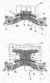
- FIG. 3 and Fig. 4 show, the other pressure medium actuators 17 and 18 are coupled in pairs with the first-mentioned pressure medium actuators 13 and 14.
- a first pressure medium actuator 13 is coupled to a third pressure medium actuator 17, while the second pressure medium actuator 14 is coupled to the fourth pressure medium actuator 18, cf.
- the pressure-medium control device 15 can in this case provide for the first and second pressure-medium actuators 13 and 14 as well as for the third and fourth pressure-medium actuators 17 and 18 respectively the operating modes described above, ie the rocker operating mode, the actuating mode and the height adjustment mode, and control the pressure medium actuators accordingly , wherein the pressure medium actuators 13 and 14 on the one hand and the pressure medium actuators 17 and 18 on the other hand each individually or in combination with each other can be acted upon correspondingly with pressurized fluid.
- the pressure medium control device 15 can also provide a special short circuit connection between the pressure medium actuators, as this Fig. 3 shows.
- each pair of pressure medium actuators can be short-circuited with each other, which are not coupled to each other via the aforementioned transformer 19.
- the first pressure-medium actuator 13 can be short-circuited to the fourth pressure-medium actuator 18, while the second pressure-medium actuator 14 is short-circuited to the third pressure-medium actuator 17, so that on the positive-displacement principle with low rockers of one axle support part, the other axle-support part wobbles and vice versa.
- Fig. 4 shows an example embodiment of the pressure medium control device, which may have a plurality of switching valves advantageously in the form of multi-way switching valves.
- the said multi-way switching valves can on the one hand Shut-off valves 21 for shutting off the respective pressure actuator from the pressure source and / or the return, and on the other hand switching valves 22 for switching the fluid connections between the pressure medium actuators and between a respective pressure medium actuator and the pressure source or the return.
- the Mehrwegeschaltventile 20 are formed, arranged and interconnected, that the pressure medium actuators 13 and 14 or 17 and 18 in the aforementioned manner either with a pressure source, a return or short circuit connected or disconnected, and can also be completely shut off to hold a used position.
- FIGS. 5 and 6 Another embodiment is in the FIGS. 5 and 6 shown with respect to the formation of the wheel axles 8 and 9, the axle beam 10 or its Achsmikmaschine 10a and 10b and the pivoting to the machine frame about the pivot axis 11 and the pivoting about the pivot axis 111 substantially to the previously described embodiment of the Fig. 1 to 4 equivalent.
- Significant difference from the previously described embodiments is the arrangement of the pressure medium actuators 13 and 14th
- the other, second pressure medium actuator 14 is articulated on the one hand on one of the axle 10b and on the other hand on the Schwenkachsange 12 or a frame-fixed carrier.
- FIGS. 5 and 6 show the achslongedseitliche pivot point of the second pressure medium actuator 14 may be summarized with the articulation point of the first pressure medium actuator 13 on this axle 10a.
- the two pressure medium actuators 13 and 14 may be arranged on the same side of the axle beam 10, in particular above the axle beam 10th
- the first pressure medium actuator 13 which is articulated on both axle support parts 10a and 10b, can be used for height adjustment. By extending and retracting the first pressure medium actuator 13, the axle support parts 10a and 10b can be pivoted relative to each other, as previously by comparing the FIGS. 1 and 2 was clarified. In order to freeze a certain relative pivot position of the two axle carrier parts 10a and 10b, the pressure medium actuator 13 can be locked or locked.
- the pivotal position of the entire axle carrier 10 with respect to the pivot axis 11 can be controlled. If the axle carrier 10 is to rock up and down in the bogey mode, the pressure medium actuator 14 can be shut off from the pressure source and the return and / or switched into floating position, so that it can move freely back and forth apart from the flow resistance.
- the pressure medium control device 15 can switch the pressure medium actuator 14 in the rocker operating mode accordingly, in particular connect the opposing pressure chambers of the pressure medium actuator 14 with each other, if the pressure chambers are the same size from the displacement volume, or else connect to each other via a balancing cylinder or else so with return and fluid supply connect that a free movement is possible.
- the two pressure medium actuators 13 and 14 may be advantageously each formed as a double cylinder, wherein two pistons may be mounted on a common piston rod, which are slidably received in each case a separate cylinder and there separate two pressure chambers from each other, so that each of the separate cylinder double-acting is.
- Such double cylinders can not only in the execution of the FIGS. 5 and 6 be useful, but also in the previously explained embodiment of the FIGS. 1 to 4 Find use.
- the pressure medium control device 15 may comprise a plurality of multi-way switching valves, by means of which the pressure chambers of the pressure medium cylinders 13 and 14 selectively pressurized from a pressure source, can be depressurized to the tank and interconnected or "shorted" to fill each other in opposite directions or to empty.
- the pressure medium actuator 14 controlling the axle carrier to the machine frame may be depressurized with all the chambers to allow rocking of the axle carrier, while the pressure medium actuator 13 controlling the relative movement may be pressure connected in at least two of the four chambers, in order to maintain a middle position in which the two axle carrier parts can assume a middle position relative to one another, for example the 180 ° position shown in the figures.
- the pressure control device 15 can switch the valves so that the relative movement of the controlling pressure medium actuator 13 is pressurized so that it collapses and accordingly pivot the two axle support parts upwards.
- the other pressure medium actuator 14, which controls the absolute angular position, can be depressurized with a cylinder part be and be pressurized with the other cylinder in the extending chamber to take a middle position. If, however, a slope compensation to be made downhill, the pressure medium actuator 13 can be pressurized in its two extending chambers to the two axle support parts to each other down to overstretch, while the absolute pressure cylinder 14 can be depressurized.
- the pressure medium control device 15 can also include a curve control mode in which the rear bogey axle 9 is relieved or lifted.
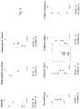
- the pressure medium actuator 14 controlling the absolute angular position to the machine frame can be pressurized to hold a certain position, while in the double cylinder 13, which controls the axle support parts to each other, at least one pressure chamber which causes a retraction (discharge mode) or both Chambers that cause a retraction (lifting mode) can be pressurized, as in the lower row of the partial views of FIG. 7 show the second and fourth illustration.
- the rear bogey axle 8 is loaded and the rear wheel is lowered accordingly, the relative cylinder 13 in both chambers, which cause an extension of the double cylinder, pressure can be applied, so that the rear axle support part 10 a driven down becomes.
- the front axle support part 10b is held in a predetermined position by freezing the pressure medium actuator 14, for example by pressurizing an extending pressure chamber and a retracting pressure chamber of the double cylinder, as the third representation in the lower row of the partial views of FIG. 7 shows.
- the Druckschaktor 14 In order to approach a specific position in the operating mode of the pressure medium control device 15, the Druckschaktor 14 is in principle connected to the pressure source or the return until the desired position is approached, whereupon the Druckstoffaktor 14 can be locked, for example by locking a switching valve.
- the other pressure medium actuator 13 can be moved by connecting to the pressure source and / or the return in a corresponding desired position and then locked to force a certain position of the two axles and hold.
Landscapes
- Engineering & Computer Science (AREA)
- Mechanical Engineering (AREA)
- Life Sciences & Earth Sciences (AREA)
- Environmental Sciences (AREA)
- Vehicle Body Suspensions (AREA)
Applications Claiming Priority (1)
| Application Number | Priority Date | Filing Date | Title |
|---|---|---|---|
| DE202017107372.6U DE202017107372U1 (de) | 2017-12-04 | 2017-12-04 | Landwirtschaftliche Ernte- und/oder Bodenbearbeitungsmaschine |
Publications (2)
| Publication Number | Publication Date |
|---|---|
| EP3491908A1 true EP3491908A1 (fr) | 2019-06-05 |
| EP3491908B1 EP3491908B1 (fr) | 2021-03-03 |
Family
ID=64604536
Family Applications (1)
| Application Number | Title | Priority Date | Filing Date |
|---|---|---|---|
| EP18210080.0A Active EP3491908B1 (fr) | 2017-12-04 | 2018-12-04 | Moissonneuse et/ou machine de traitement du sol agricole |
Country Status (2)
| Country | Link |
|---|---|
| EP (1) | EP3491908B1 (fr) |
| DE (1) | DE202017107372U1 (fr) |
Families Citing this family (2)
| Publication number | Priority date | Publication date | Assignee | Title |
|---|---|---|---|---|
| EP3845400A1 (fr) * | 2020-01-04 | 2021-07-07 | Trachsel Technik AG | Châssis pour remorque de véhicule et remorque de véhicule |
| WO2022229953A1 (fr) * | 2021-04-26 | 2022-11-03 | Ree Automotive Ltd. | Ensemble coin de véhicule à deux essieux |
Citations (4)
| Publication number | Priority date | Publication date | Assignee | Title |
|---|---|---|---|---|
| US2918292A (en) * | 1955-09-07 | 1959-12-22 | Scott Viner Company | Leveling device for mobile viner |
| EP3069598A1 (fr) * | 2015-03-20 | 2016-09-21 | PÖTTINGER Landtechnik GmbH | Presse à fourrage |
| EP3069600A1 (fr) * | 2015-03-20 | 2016-09-21 | PÖTTINGER Landtechnik GmbH | Moissonneuse |
| DE102015006221A1 (de) * | 2015-03-20 | 2016-09-22 | Alois Pöttinger Maschinenfabrik Ges.m.b.H. | Erntemaschine |
Family Cites Families (1)
| Publication number | Priority date | Publication date | Assignee | Title |
|---|---|---|---|---|
| US5794966A (en) * | 1996-02-05 | 1998-08-18 | Macleod; Kenneth J. | Vehicular suspension system |
-
2017
- 2017-12-04 DE DE202017107372.6U patent/DE202017107372U1/de active Active
-
2018
- 2018-12-04 EP EP18210080.0A patent/EP3491908B1/fr active Active
Patent Citations (4)
| Publication number | Priority date | Publication date | Assignee | Title |
|---|---|---|---|---|
| US2918292A (en) * | 1955-09-07 | 1959-12-22 | Scott Viner Company | Leveling device for mobile viner |
| EP3069598A1 (fr) * | 2015-03-20 | 2016-09-21 | PÖTTINGER Landtechnik GmbH | Presse à fourrage |
| EP3069600A1 (fr) * | 2015-03-20 | 2016-09-21 | PÖTTINGER Landtechnik GmbH | Moissonneuse |
| DE102015006221A1 (de) * | 2015-03-20 | 2016-09-22 | Alois Pöttinger Maschinenfabrik Ges.m.b.H. | Erntemaschine |
Also Published As
| Publication number | Publication date |
|---|---|
| EP3491908B1 (fr) | 2021-03-03 |
| DE202017107372U1 (de) | 2019-03-06 |
Similar Documents
| Publication | Publication Date | Title |
|---|---|---|
| EP1269825B1 (fr) | Agencement de roue porteuse pour une machine agricole | |
| EP0958730B1 (fr) | Dispositif pour actionner et réguler des cylindres de travail | |
| EP4147563B1 (fr) | Moissonneuse dotée d'une tête réglable en hauteur | |
| DE102016217593A1 (de) | Kompaktes Bodenbearbeitungsgerät | |
| DE2428917B2 (de) | Bodenbearbeitungsgeraet | |
| EP3753407B1 (fr) | Appareil agricole à réglage de l'inclinaison amélioré | |
| EP4021177A1 (fr) | Engin agricole à suspension améliorée | |
| EP2281435B1 (fr) | Combinaison d'andain | |
| EP3302016B1 (fr) | Charrue semi-portée | |
| EP3491908B1 (fr) | Moissonneuse et/ou machine de traitement du sol agricole | |
| EP3254546B1 (fr) | Engin agricole | |
| DE1557775A1 (de) | Regelmittel fuer Zugwiderstand und Arbeitstiefe | |
| EP2883722B1 (fr) | Moissonneuse automotrice dotée d'un couplage d'essieu hydraulique anti-roulis | |
| EP4021178A1 (fr) | Engin agricole à suspension améliorée | |
| DE102018209193A1 (de) | Landwirtschaftliches Bodenbearbeitungsgerät und Verfahren zu dessen Betrieb | |
| EP4165961B1 (fr) | Charrue réversible portée | |
| EP1522213B1 (fr) | Dispositif pour la fixation d'une machine agricole | |
| EP3598882B1 (fr) | Accessoire agricole | |
| DE102013101762A1 (de) | An einem Schlepper ankuppelbare Landmaschine | |
| EP3354123B1 (fr) | Appareil de traitement du sol agricole | |
| EP4124221B1 (fr) | Machine agricole et combinaison de machines agricoles | |
| DE10215033A1 (de) | Landwirtschaftliches Anhängerfahrzeug mit einer Einrichtung zum Verschieben der Ladung | |
| DE2436457B2 (de) | Hydraulische Steuervorrichtung für die Ausheb- und Absenkbewegungen eines mit mehreren Pflugscharen versehenen Pfluges | |
| AT502053B1 (de) | Anbauvorrichtung für eine landmaschine | |
| DE202022002936U1 (de) | Landwirtschaftliches Gerät mit verbesserter Neigungsregelung |
Legal Events
| Date | Code | Title | Description |
|---|---|---|---|
| PUAI | Public reference made under article 153(3) epc to a published international application that has entered the european phase |
Free format text: ORIGINAL CODE: 0009012 |
|
| STAA | Information on the status of an ep patent application or granted ep patent |
Free format text: STATUS: THE APPLICATION HAS BEEN PUBLISHED |
|
| AK | Designated contracting states |
Kind code of ref document: A1 Designated state(s): AL AT BE BG CH CY CZ DE DK EE ES FI FR GB GR HR HU IE IS IT LI LT LU LV MC MK MT NL NO PL PT RO RS SE SI SK SM TR |
|
| AX | Request for extension of the european patent |
Extension state: BA ME |
|
| STAA | Information on the status of an ep patent application or granted ep patent |
Free format text: STATUS: REQUEST FOR EXAMINATION WAS MADE |
|
| 17P | Request for examination filed |
Effective date: 20191128 |
|
| RBV | Designated contracting states (corrected) |
Designated state(s): AL AT BE BG CH CY CZ DE DK EE ES FI FR GB GR HR HU IE IS IT LI LT LU LV MC MK MT NL NO PL PT RO RS SE SI SK SM TR |
|
| GRAP | Despatch of communication of intention to grant a patent |
Free format text: ORIGINAL CODE: EPIDOSNIGR1 |
|
| RIC1 | Information provided on ipc code assigned before grant |
Ipc: A01D 75/28 20060101ALI20200820BHEP Ipc: A01F 15/08 20060101AFI20200820BHEP Ipc: B60G 21/02 20060101ALI20200820BHEP Ipc: B60G 5/06 20060101ALI20200820BHEP Ipc: B60G 21/067 20060101ALI20200820BHEP Ipc: A01F 15/07 20060101ALN20200820BHEP Ipc: B60G 21/00 20060101ALI20200820BHEP |
|
| STAA | Information on the status of an ep patent application or granted ep patent |
Free format text: STATUS: GRANT OF PATENT IS INTENDED |
|
| INTG | Intention to grant announced |
Effective date: 20200924 |
|
| GRAS | Grant fee paid |
Free format text: ORIGINAL CODE: EPIDOSNIGR3 |
|
| GRAA | (expected) grant |
Free format text: ORIGINAL CODE: 0009210 |
|
| STAA | Information on the status of an ep patent application or granted ep patent |
Free format text: STATUS: THE PATENT HAS BEEN GRANTED |
|
| AK | Designated contracting states |
Kind code of ref document: B1 Designated state(s): AL AT BE BG CH CY CZ DE DK EE ES FI FR GB GR HR HU IE IS IT LI LT LU LV MC MK MT NL NO PL PT RO RS SE SI SK SM TR |
|
| REG | Reference to a national code |
Ref country code: GB Ref legal event code: FG4D Free format text: NOT ENGLISH |
|
| REG | Reference to a national code |
Ref country code: CH Ref legal event code: EP Ref country code: AT Ref legal event code: REF Ref document number: 1366165 Country of ref document: AT Kind code of ref document: T Effective date: 20210315 |
|
| REG | Reference to a national code |
Ref country code: DE Ref legal event code: R096 Ref document number: 502018004121 Country of ref document: DE |
|
| REG | Reference to a national code |
Ref country code: IE Ref legal event code: FG4D Free format text: LANGUAGE OF EP DOCUMENT: GERMAN |
|
| REG | Reference to a national code |
Ref country code: NL Ref legal event code: FP |
|
| REG | Reference to a national code |
Ref country code: LT Ref legal event code: MG9D |
|
| PG25 | Lapsed in a contracting state [announced via postgrant information from national office to epo] |
Ref country code: LT Free format text: LAPSE BECAUSE OF FAILURE TO SUBMIT A TRANSLATION OF THE DESCRIPTION OR TO PAY THE FEE WITHIN THE PRESCRIBED TIME-LIMIT Effective date: 20210303 Ref country code: NO Free format text: LAPSE BECAUSE OF FAILURE TO SUBMIT A TRANSLATION OF THE DESCRIPTION OR TO PAY THE FEE WITHIN THE PRESCRIBED TIME-LIMIT Effective date: 20210603 Ref country code: BG Free format text: LAPSE BECAUSE OF FAILURE TO SUBMIT A TRANSLATION OF THE DESCRIPTION OR TO PAY THE FEE WITHIN THE PRESCRIBED TIME-LIMIT Effective date: 20210603 Ref country code: HR Free format text: LAPSE BECAUSE OF FAILURE TO SUBMIT A TRANSLATION OF THE DESCRIPTION OR TO PAY THE FEE WITHIN THE PRESCRIBED TIME-LIMIT Effective date: 20210303 Ref country code: FI Free format text: LAPSE BECAUSE OF FAILURE TO SUBMIT A TRANSLATION OF THE DESCRIPTION OR TO PAY THE FEE WITHIN THE PRESCRIBED TIME-LIMIT Effective date: 20210303 Ref country code: GR Free format text: LAPSE BECAUSE OF FAILURE TO SUBMIT A TRANSLATION OF THE DESCRIPTION OR TO PAY THE FEE WITHIN THE PRESCRIBED TIME-LIMIT Effective date: 20210604 |
|
| PG25 | Lapsed in a contracting state [announced via postgrant information from national office to epo] |
Ref country code: RS Free format text: LAPSE BECAUSE OF FAILURE TO SUBMIT A TRANSLATION OF THE DESCRIPTION OR TO PAY THE FEE WITHIN THE PRESCRIBED TIME-LIMIT Effective date: 20210303 Ref country code: LV Free format text: LAPSE BECAUSE OF FAILURE TO SUBMIT A TRANSLATION OF THE DESCRIPTION OR TO PAY THE FEE WITHIN THE PRESCRIBED TIME-LIMIT Effective date: 20210303 Ref country code: PL Free format text: LAPSE BECAUSE OF FAILURE TO SUBMIT A TRANSLATION OF THE DESCRIPTION OR TO PAY THE FEE WITHIN THE PRESCRIBED TIME-LIMIT Effective date: 20210303 Ref country code: SE Free format text: LAPSE BECAUSE OF FAILURE TO SUBMIT A TRANSLATION OF THE DESCRIPTION OR TO PAY THE FEE WITHIN THE PRESCRIBED TIME-LIMIT Effective date: 20210303 |
|
| PG25 | Lapsed in a contracting state [announced via postgrant information from national office to epo] |
Ref country code: EE Free format text: LAPSE BECAUSE OF FAILURE TO SUBMIT A TRANSLATION OF THE DESCRIPTION OR TO PAY THE FEE WITHIN THE PRESCRIBED TIME-LIMIT Effective date: 20210303 Ref country code: CZ Free format text: LAPSE BECAUSE OF FAILURE TO SUBMIT A TRANSLATION OF THE DESCRIPTION OR TO PAY THE FEE WITHIN THE PRESCRIBED TIME-LIMIT Effective date: 20210303 Ref country code: SM Free format text: LAPSE BECAUSE OF FAILURE TO SUBMIT A TRANSLATION OF THE DESCRIPTION OR TO PAY THE FEE WITHIN THE PRESCRIBED TIME-LIMIT Effective date: 20210303 |
|
| PG25 | Lapsed in a contracting state [announced via postgrant information from national office to epo] |
Ref country code: IS Free format text: LAPSE BECAUSE OF FAILURE TO SUBMIT A TRANSLATION OF THE DESCRIPTION OR TO PAY THE FEE WITHIN THE PRESCRIBED TIME-LIMIT Effective date: 20210703 Ref country code: SK Free format text: LAPSE BECAUSE OF FAILURE TO SUBMIT A TRANSLATION OF THE DESCRIPTION OR TO PAY THE FEE WITHIN THE PRESCRIBED TIME-LIMIT Effective date: 20210303 Ref country code: RO Free format text: LAPSE BECAUSE OF FAILURE TO SUBMIT A TRANSLATION OF THE DESCRIPTION OR TO PAY THE FEE WITHIN THE PRESCRIBED TIME-LIMIT Effective date: 20210303 Ref country code: PT Free format text: LAPSE BECAUSE OF FAILURE TO SUBMIT A TRANSLATION OF THE DESCRIPTION OR TO PAY THE FEE WITHIN THE PRESCRIBED TIME-LIMIT Effective date: 20210705 |
|
| REG | Reference to a national code |
Ref country code: DE Ref legal event code: R097 Ref document number: 502018004121 Country of ref document: DE |
|
| PLBE | No opposition filed within time limit |
Free format text: ORIGINAL CODE: 0009261 |
|
| STAA | Information on the status of an ep patent application or granted ep patent |
Free format text: STATUS: NO OPPOSITION FILED WITHIN TIME LIMIT |
|
| PG25 | Lapsed in a contracting state [announced via postgrant information from national office to epo] |
Ref country code: ES Free format text: LAPSE BECAUSE OF FAILURE TO SUBMIT A TRANSLATION OF THE DESCRIPTION OR TO PAY THE FEE WITHIN THE PRESCRIBED TIME-LIMIT Effective date: 20210303 Ref country code: DK Free format text: LAPSE BECAUSE OF FAILURE TO SUBMIT A TRANSLATION OF THE DESCRIPTION OR TO PAY THE FEE WITHIN THE PRESCRIBED TIME-LIMIT Effective date: 20210303 Ref country code: AL Free format text: LAPSE BECAUSE OF FAILURE TO SUBMIT A TRANSLATION OF THE DESCRIPTION OR TO PAY THE FEE WITHIN THE PRESCRIBED TIME-LIMIT Effective date: 20210303 |
|
| 26N | No opposition filed |
Effective date: 20211206 |
|
| PG25 | Lapsed in a contracting state [announced via postgrant information from national office to epo] |
Ref country code: SI Free format text: LAPSE BECAUSE OF FAILURE TO SUBMIT A TRANSLATION OF THE DESCRIPTION OR TO PAY THE FEE WITHIN THE PRESCRIBED TIME-LIMIT Effective date: 20210303 |
|
| PG25 | Lapsed in a contracting state [announced via postgrant information from national office to epo] |
Ref country code: IT Free format text: LAPSE BECAUSE OF FAILURE TO SUBMIT A TRANSLATION OF THE DESCRIPTION OR TO PAY THE FEE WITHIN THE PRESCRIBED TIME-LIMIT Effective date: 20210303 |
|
| PG25 | Lapsed in a contracting state [announced via postgrant information from national office to epo] |
Ref country code: IS Free format text: LAPSE BECAUSE OF FAILURE TO SUBMIT A TRANSLATION OF THE DESCRIPTION OR TO PAY THE FEE WITHIN THE PRESCRIBED TIME-LIMIT Effective date: 20210703 |
|
| PG25 | Lapsed in a contracting state [announced via postgrant information from national office to epo] |
Ref country code: MC Free format text: LAPSE BECAUSE OF FAILURE TO SUBMIT A TRANSLATION OF THE DESCRIPTION OR TO PAY THE FEE WITHIN THE PRESCRIBED TIME-LIMIT Effective date: 20210303 |
|
| REG | Reference to a national code |
Ref country code: CH Ref legal event code: PL |
|
| REG | Reference to a national code |
Ref country code: BE Ref legal event code: MM Effective date: 20211231 |
|
| PG25 | Lapsed in a contracting state [announced via postgrant information from national office to epo] |
Ref country code: LU Free format text: LAPSE BECAUSE OF NON-PAYMENT OF DUE FEES Effective date: 20211204 |
|
| PG25 | Lapsed in a contracting state [announced via postgrant information from national office to epo] |
Ref country code: BE Free format text: LAPSE BECAUSE OF NON-PAYMENT OF DUE FEES Effective date: 20211231 |
|
| PG25 | Lapsed in a contracting state [announced via postgrant information from national office to epo] |
Ref country code: LI Free format text: LAPSE BECAUSE OF NON-PAYMENT OF DUE FEES Effective date: 20211231 Ref country code: CH Free format text: LAPSE BECAUSE OF NON-PAYMENT OF DUE FEES Effective date: 20211231 |
|
| PG25 | Lapsed in a contracting state [announced via postgrant information from national office to epo] |
Ref country code: CY Free format text: LAPSE BECAUSE OF FAILURE TO SUBMIT A TRANSLATION OF THE DESCRIPTION OR TO PAY THE FEE WITHIN THE PRESCRIBED TIME-LIMIT Effective date: 20210303 |
|
| P01 | Opt-out of the competence of the unified patent court (upc) registered |
Effective date: 20230613 |
|
| PG25 | Lapsed in a contracting state [announced via postgrant information from national office to epo] |
Ref country code: HU Free format text: LAPSE BECAUSE OF FAILURE TO SUBMIT A TRANSLATION OF THE DESCRIPTION OR TO PAY THE FEE WITHIN THE PRESCRIBED TIME-LIMIT; INVALID AB INITIO Effective date: 20181204 |
|
| GBPC | Gb: european patent ceased through non-payment of renewal fee |
Effective date: 20221204 |
|
| PG25 | Lapsed in a contracting state [announced via postgrant information from national office to epo] |
Ref country code: GB Free format text: LAPSE BECAUSE OF NON-PAYMENT OF DUE FEES Effective date: 20221204 |
|
| PG25 | Lapsed in a contracting state [announced via postgrant information from national office to epo] |
Ref country code: MK Free format text: LAPSE BECAUSE OF FAILURE TO SUBMIT A TRANSLATION OF THE DESCRIPTION OR TO PAY THE FEE WITHIN THE PRESCRIBED TIME-LIMIT Effective date: 20210303 |
|
| PG25 | Lapsed in a contracting state [announced via postgrant information from national office to epo] |
Ref country code: TR Free format text: LAPSE BECAUSE OF FAILURE TO SUBMIT A TRANSLATION OF THE DESCRIPTION OR TO PAY THE FEE WITHIN THE PRESCRIBED TIME-LIMIT Effective date: 20210303 |
|
| PG25 | Lapsed in a contracting state [announced via postgrant information from national office to epo] |
Ref country code: MT Free format text: LAPSE BECAUSE OF FAILURE TO SUBMIT A TRANSLATION OF THE DESCRIPTION OR TO PAY THE FEE WITHIN THE PRESCRIBED TIME-LIMIT Effective date: 20210303 |
|
| REG | Reference to a national code |
Ref country code: AT Ref legal event code: MM01 Ref document number: 1366165 Country of ref document: AT Kind code of ref document: T Effective date: 20231204 |
|
| PG25 | Lapsed in a contracting state [announced via postgrant information from national office to epo] |
Ref country code: AT Free format text: LAPSE BECAUSE OF NON-PAYMENT OF DUE FEES Effective date: 20231204 |
|
| PGFP | Annual fee paid to national office [announced via postgrant information from national office to epo] |
Ref country code: DE Payment date: 20251216 Year of fee payment: 8 |
|
| PGFP | Annual fee paid to national office [announced via postgrant information from national office to epo] |
Ref country code: NL Payment date: 20251217 Year of fee payment: 8 Ref country code: FR Payment date: 20251229 Year of fee payment: 8 |
|
| PGFP | Annual fee paid to national office [announced via postgrant information from national office to epo] |
Ref country code: IE Payment date: 20251229 Year of fee payment: 8 |
|
| PGFP | Annual fee paid to national office [announced via postgrant information from national office to epo] |
Ref country code: AT Payment date: 20260410 Year of fee payment: 5 |