EP3492191B1 - Procédé de fabrication d'une armure de corps - Google Patents
Procédé de fabrication d'une armure de corps Download PDFInfo
- Publication number
- EP3492191B1 EP3492191B1 EP18209999.4A EP18209999A EP3492191B1 EP 3492191 B1 EP3492191 B1 EP 3492191B1 EP 18209999 A EP18209999 A EP 18209999A EP 3492191 B1 EP3492191 B1 EP 3492191B1
- Authority
- EP
- European Patent Office
- Prior art keywords
- armor
- elements
- another
- blank
- armor elements
- Prior art date
- Legal status (The legal status is an assumption and is not a legal conclusion. Google has not performed a legal analysis and makes no representation as to the accuracy of the status listed.)
- Active
Links
Images


Classifications
-
- F—MECHANICAL ENGINEERING; LIGHTING; HEATING; WEAPONS; BLASTING
- F41—WEAPONS
- F41H—ARMOUR; ARMOURED TURRETS; ARMOURED OR ARMED VEHICLES; MEANS OF ATTACK OR DEFENCE, e.g. CAMOUFLAGE, IN GENERAL
- F41H5/00—Armour; Armour plates
- F41H5/02—Plate construction
- F41H5/04—Plate construction composed of more than one layer
- F41H5/0442—Layered armour containing metal
- F41H5/0457—Metal layers in combination with additional layers made of fibres, fabrics or plastics
-
- F—MECHANICAL ENGINEERING; LIGHTING; HEATING; WEAPONS; BLASTING
- F41—WEAPONS
- F41H—ARMOUR; ARMOURED TURRETS; ARMOURED OR ARMED VEHICLES; MEANS OF ATTACK OR DEFENCE, e.g. CAMOUFLAGE, IN GENERAL
- F41H1/00—Personal protection gear
- F41H1/02—Armoured or projectile- or missile-resistant garments; Composite protection fabrics
-
- F—MECHANICAL ENGINEERING; LIGHTING; HEATING; WEAPONS; BLASTING
- F41—WEAPONS
- F41H—ARMOUR; ARMOURED TURRETS; ARMOURED OR ARMED VEHICLES; MEANS OF ATTACK OR DEFENCE, e.g. CAMOUFLAGE, IN GENERAL
- F41H5/00—Armour; Armour plates
- F41H5/02—Plate construction
- F41H5/04—Plate construction composed of more than one layer
- F41H5/0492—Layered armour containing hard elements, e.g. plates, spheres, rods, separated from each other, the elements being connected to a further flexible layer or being embedded in a plastics or an elastomer matrix
-
- A—HUMAN NECESSITIES
- A41—WEARING APPAREL
- A41D—OUTERWEAR; PROTECTIVE GARMENTS; ACCESSORIES
- A41D2500/00—Materials for garments
- A41D2500/50—Synthetic resins or rubbers
- A41D2500/52—Synthetic resins or rubbers in sheet form
-
- A—HUMAN NECESSITIES
- A41—WEARING APPAREL
- A41D—OUTERWEAR; PROTECTIVE GARMENTS; ACCESSORIES
- A41D31/00—Materials specially adapted for outerwear
- A41D31/04—Materials specially adapted for outerwear characterised by special function or use
- A41D31/24—Resistant to mechanical stress, e.g. pierce-proof
-
- B—PERFORMING OPERATIONS; TRANSPORTING
- B32—LAYERED PRODUCTS
- B32B—LAYERED PRODUCTS, i.e. PRODUCTS BUILT-UP OF STRATA OF FLAT OR NON-FLAT, e.g. CELLULAR OR HONEYCOMB, FORM
- B32B38/00—Ancillary operations in connection with laminating processes
- B32B38/0012—Mechanical treatment, e.g. roughening, deforming, stretching
-
- F—MECHANICAL ENGINEERING; LIGHTING; HEATING; WEAPONS; BLASTING
- F41—WEAPONS
- F41H—ARMOUR; ARMOURED TURRETS; ARMOURED OR ARMED VEHICLES; MEANS OF ATTACK OR DEFENCE, e.g. CAMOUFLAGE, IN GENERAL
- F41H5/00—Armour; Armour plates
- F41H5/02—Plate construction
- F41H5/04—Plate construction composed of more than one layer
- F41H5/0414—Layered armour containing ceramic material
- F41H5/0421—Ceramic layers in combination with metal layers
-
- F—MECHANICAL ENGINEERING; LIGHTING; HEATING; WEAPONS; BLASTING
- F41—WEAPONS
- F41H—ARMOUR; ARMOURED TURRETS; ARMOURED OR ARMED VEHICLES; MEANS OF ATTACK OR DEFENCE, e.g. CAMOUFLAGE, IN GENERAL
- F41H5/00—Armour; Armour plates
- F41H5/02—Plate construction
- F41H5/04—Plate construction composed of more than one layer
- F41H5/0414—Layered armour containing ceramic material
- F41H5/0428—Ceramic layers in combination with additional layers made of fibres, fabrics or plastics
-
- Y—GENERAL TAGGING OF NEW TECHNOLOGICAL DEVELOPMENTS; GENERAL TAGGING OF CROSS-SECTIONAL TECHNOLOGIES SPANNING OVER SEVERAL SECTIONS OF THE IPC; TECHNICAL SUBJECTS COVERED BY FORMER USPC CROSS-REFERENCE ART COLLECTIONS [XRACs] AND DIGESTS
- Y10—TECHNICAL SUBJECTS COVERED BY FORMER USPC
- Y10T—TECHNICAL SUBJECTS COVERED BY FORMER US CLASSIFICATION
- Y10T156/00—Adhesive bonding and miscellaneous chemical manufacture
- Y10T156/10—Methods of surface bonding and/or assembly therefor
- Y10T156/1002—Methods of surface bonding and/or assembly therefor with permanent bending or reshaping or surface deformation of self sustaining lamina
Definitions
- the invention relates to a method for producing body armor with several armor elements that are connected to one another.
- Body armor has long been known in the state of the art. It comes in various forms, allowing the body to be protected against various threats.
- Body armor can be designed as garments, such as vests or jackets, or as fixed elements. In principle, it could also be considered as armor.
- body armor typically consists of several interconnected armor elements.
- the connection is articulated to allow the wearer the greatest possible freedom of movement.
- it must be ensured that the protection intended by the body armor is still guaranteed, particularly at the joints between the armor elements and in the spaces between two interconnected armor elements.
- Body armor of the type described here can be designed as stab- and cut-resistant armor, for example, in the form of stab- and/or cut-resistant vests or jackets. In principle, bulletproof body armor is also possible.
- the various armor elements consist of a material selected for the specific threat the body armor is intended to defend against.
- slash- and/or stab-resistant body armor uses metal plates, preferably aluminum plates, as the armor element.
- Other body armor can also use fiber-reinforced plastics, composite materials, or ceramic elements.
- the armor elements are adapted to the human body shape. If the body armor is designed in the form of a garment, different sizes and different "patterns" can be created for men and women.
- the armor elements are formed in different geometric contours and shapes, for example, by cutting or punching, whereby the armor elements are flat and essentially two-dimensional. They are then formed into the respective three-dimensional shape required for their use as an armor element, for example, through forming processes such as rolling or deep drawing.
- the disadvantage is that with an increasing number of armor elements, which is necessary for a high level of wearing comfort, the effort required to produce such body armor increases significantly, since a wide variety of three-dimensional shapes must be used to bring the individual armor elements into the desired shape.
- a stab-proof vest that consists of a multitude of square plates that are arranged in an articulated manner. Although the plates can be curved, the special method of manufacture and arrangement of the plates results in gaps of varying sizes between two plates, so that the penetration of a particularly slender blade cannot be reliably prevented.
- JP H03 258 423 A A process is known with which several body components can be manufactured simultaneously in a punching and pressing process.
- the invention is therefore based on the object of improving a method for producing body armour so that it can be produced more quickly and cost-effectively.
- the inventive design of the method ensures that the individual armor elements do not have to be formed into the desired shape separately and in separate forming steps. Instead, the armor elements that are part of the armor blank can be formed together, which significantly reduces the number of required forming steps and thus lowers production time and thus also production costs. Furthermore, this ensures that the various armor elements in the subsequent body armor are optimally adapted and coordinated to one another.
- the individual armor elements are connected to one another or firmly positioned relative to one another in process step a). This ensures that the individual armor elements are deformed in a predetermined manner in process step b).
- the firm positioning of the armor elements relative to one another can be achieved, for example, by fixing the individual armor elements on or to a base. This allows them to move freely during the forming of the The armor blanks cannot move relative to each other.
- the base can have fixing elements, such as fasteners or recesses in the shape of the individual armor elements, similar to a puzzle.
- the armor elements can also be attached to the base, for example, using a removable adhesive.
- the armor elements that were separated from each other in process step c) are connected to each other in an articulated manner.
- the at least two armor elements of the armor blank are connected to each other in an arrangement in which they are also connected to each other in an articulated manner in process step d).
- the armor blank advantageously has the largest possible number of armor elements, for example, four, five, six, or eight.
- the armor blank already has all the armor elements necessary for body armor.
- body armor the individual armor elements are articulated together in a specific arrangement.
- the side edges and geometric shape elements of the adjacent armor elements, which point towards the respective neighboring element, are adapted to one another in order to maintain the desired properties, particularly in the space between the adjacent armor elements. In this area, the armor elements must therefore be optimally coordinated with one another in their geometric shape and three-dimensional design.
- the at least two armor elements in the armor blank are integrally connected to one another, in particular welded or glued to one another, or formed as a single piece.
- the armor blank is produced, in particular cut or punched, from a metal plate, in particular an aluminum plate, before being provided. Laser cutting processes or water cutting processes can be used, as can punching or conventional cutting processes.
- the individual armor elements are cut out of a plate-shaped element, for example the metal plate, whereby they remain connected to one another via webs or are reconnected to one another at these points.
- the interconnected armor elements are already connected to one another in the position and orientation in which they are also connected to one another in the finished body armor. If the armor elements are first manufactured separately and then connected to one another, preferably integrally, any waste that may arise can be reduced, so that the manufacturing costs can be further reduced in this respect. However, the subsequent connection of the armor elements to form the armor blank requires an additional process step.
- the webs or elements connecting the armor elements within the armor blank are separated in process step c), so that the individual armor elements are separated from each other. They are then hinged together, preferably in the same orientation and arrangement.
- the forming device preferably comprises a rolling device with at least one forming roller or is preferably a rolling device with at least one forming roller.
- the forming roller advantageously has different radii of curvature. Different radii of curvature can occur in different circumferential regions of the forming roller, so that the forming roller does not have a circular cross-section in these regions. Alternatively or additionally, the forming roller can also have different radii of curvature along its axial direction, so that a longitudinal section is not a rectangle.
- the two configurations can be combined, allowing the use of very irregularly shaped forming rollers.
- This allows for complete three-dimensional forming of the individual armor elements without the need for separate and additional forming steps.
- Particularly preferred is the forming of the armor blank in a single forming step. This minimizes the number of required steps and further shortens the manufacturing process.
- the forming device can comprise further devices, for example, at least one pressing device and/or at least one deep-drawing device and/or at least one punching device.
- the forming device can comprise further devices, for example, at least one pressing device and/or at least one deep-drawing device and/or at least one punching device.
- only one forming step is required to form the armor blank in at least one of these devices, preferably in all of the devices present, in order to achieve the desired shape of the armor blank.
- Body armor that can be produced or is produced using one of the methods described here is preferably protective clothing, in particular a protective vest, a protective jacket, an arm protection element, a leg protection element, or a groin protection element.
- protective clothing advantageously incorporates the individual armor elements, which are connected to one another in an articulated manner, so that they are not visible from the outside.
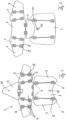
- Figure 1 shows an armor blank 2, which has several armor elements 4, which are connected to each other via connecting webs 6.
- the armor blank 2 from Figure 1 includes all armor elements 4 that are necessary for a shoulder element of body armor in the embodiment shown.
- Figure 2 shows the armor elements 4 as they are arranged in the body armor.
- the upper middle armor elements 4 are positioned in the same orientation and arrangement to each other as they are already in the Figure 1 shown armor blank 2.
- All armor elements 4 in the Figures 1 and 2 have slots 8, which are arranged in such a way that the slots 8 of two adjacently arranged armor elements 4 run parallel to each other.
- Connecting elements are inserted into these slots 8, which provide an articulated connection of the individual armor elements 4 in the Figure 2
- Two of the armor elements made of Figure 1 They also each have a further connecting element 10, by which these two armor elements 4 can be connected to each other. This is shown in Figure 2
- the two connecting elements 10 connect the two armor elements 4 in the embodiment shown.
- Figure 1 The three armor elements 4 shown below are shown in the correct arrangement relative to each other, but will be arranged in the later body armor in the Figure 2 shown orientation, i.e. rotated by 180°.
- the arrangement of Figure 1 of the armor blank 2 is chosen to reduce possible waste.
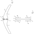
- FIG 3 schematically shows another armor blank 2, which has two armor elements 4, which are again connected to each other via connecting webs 6. These can be adhesive points, welded joints, or one-piece webs made of the same material as the armor blank 2.
- Each of the armor elements 4 has slots 8, which are arranged parallel to each other in the illustrated embodiment. This part is shown in Figure 4 shown enlarged. The slots 8 are already positioned, which are necessary for later connection of the separated armor elements 4.
- the connecting webs 6 in the illustrated embodiment are formed integrally with the armor elements 4, since the armor elements 4 and thus the armor blank 2 were cut out of a single-piece aluminum plate.
- Figure 5 shows the armor blank 2 from Figure 3 after forming. It can be seen that from the two-dimensional flat design Figure 3 a curved design in Figure 5 This can be done, for example, by a forming step with a rolling device.
- the armor blank 2 has different radii of curvature in different areas. This can also be achieved in a single forming step, for example, by the forming roller having different circumferential radii.
- the armor elements 4 are separated from each other.
- the connecting webs 6 have been removed, so that the armor elements 4 are separated from one another.
- the armor elements 4 are connected to one another via connecting elements known from the prior art in order to achieve mobility of the wearer of the body armor.
- Figure 7 shows two armor elements 4 and a base 10.
- the base 10 has two recesses 12 into which the armor elements can be inserted. Since the recesses 12 are adapted in shape and size to the armor elements 4, the armor elements 4 cannot move in the recesses 12 and, in particular, cannot shift relative to one another, so that they are firmly positioned relative to one another.
Landscapes
- Engineering & Computer Science (AREA)
- General Engineering & Computer Science (AREA)
- Ceramic Engineering (AREA)
- Aiming, Guidance, Guns With A Light Source, Armor, Camouflage, And Targets (AREA)
- Shaping Metal By Deep-Drawing, Or The Like (AREA)
- Professional, Industrial, Or Sporting Protective Garments (AREA)
Claims (7)
- Procédé de fabrication d'une armure pour le corps, comprenant plusieurs éléments d'armure (4) reliés entre eux, le procédé comprenant les étapes suivantes consistant à :a) fournir une ébauche d'armure (2) comprenant au moins deux éléments d'armure (4) reliés entre eux ou positionnés de manière fixe l'un par rapport à l'autre,b) déformer l'ébauche d'armure (2) dans au moins un dispositif de déformation, de manière à déformer lesdits au moins deux éléments d'armure (4), l'ébauche d'armure (2) présentant des rayons de courbure différents dans différentes zones,c) séparer lesdits au moins deux éléments d'armure (4) reliés entre eux, etd) relier de manière articulée les éléments d'armure séparés (4),lesdits au moins deux éléments d'armure (4) de l'ébauche d'armure (2) étant reliés entre eux selon une disposition dans laquelle on les relie entre eux également de manière articulée dans l'étape d) du procédé.
- Procédé selon la revendication 1,
caractérisé en ce que dans l'étape d) du procédé, on relie les éléments d'armure (4) entre eux de manière articulée, qui ont été séparés l'un de l'autre dans l'étape c) du procédé. - Procédé selon l'une des revendications précédentes,
caractérisé en ce que lesdits au moins deux éléments d'armure (4) dans l'ébauche d'armure (2) sont reliés entre eux par coopération de matière, en particulier soudés ou collés entre eux ou formés d'une seule pièce. - Procédé selon l'une des revendications précédentes,
caractérisé en ce qu'avant de fournir l'ébauche d'armure (2), on la réalise en particulier par découpe ou par poinçonnage à partir d'une plaque métallique, en particulier à partir d'une plaque d'acier. - Procédé selon l'une des revendications précédentes,
caractérisé en ce que le dispositif de déformation comporte un dispositif de laminage ayant au moins un cylindre de déformation, et en ce qu'il est de préférence un dispositif de laminage ayant au moins un cylindre de déformation. - Procédé selon la revendication 5,
caractérisé en ce que ledit au moins un cylindre de déformation présente différents rayons de courbure. - Procédé selon l'une des revendications précédentes,
caractérisé en ce que la déformation de l'ébauche d'armure (2) est effectuée en une seule étape de déformation.
Priority Applications (1)
| Application Number | Priority Date | Filing Date | Title |
|---|---|---|---|
| RS20250734A RS67072B1 (sr) | 2017-12-04 | 2018-12-04 | Postupak za proizvodnju pancira za ličnu zaštitu |
Applications Claiming Priority (1)
| Application Number | Priority Date | Filing Date | Title |
|---|---|---|---|
| DE102017128764.7A DE102017128764A1 (de) | 2017-12-04 | 2017-12-04 | Verfahren zum Herstellen einer Körperpanzerung |
Publications (3)
| Publication Number | Publication Date |
|---|---|
| EP3492191A1 EP3492191A1 (fr) | 2019-06-05 |
| EP3492191B1 true EP3492191B1 (fr) | 2025-04-30 |
| EP3492191C0 EP3492191C0 (fr) | 2025-04-30 |
Family
ID=64604497
Family Applications (1)
| Application Number | Title | Priority Date | Filing Date |
|---|---|---|---|
| EP18209999.4A Active EP3492191B1 (fr) | 2017-12-04 | 2018-12-04 | Procédé de fabrication d'une armure de corps |
Country Status (7)
| Country | Link |
|---|---|
| US (1) | US10928165B2 (fr) |
| EP (1) | EP3492191B1 (fr) |
| CA (1) | CA3026428A1 (fr) |
| DE (1) | DE102017128764A1 (fr) |
| ES (1) | ES3037070T3 (fr) |
| PL (1) | PL3492191T3 (fr) |
| RS (1) | RS67072B1 (fr) |
Families Citing this family (1)
| Publication number | Priority date | Publication date | Assignee | Title |
|---|---|---|---|---|
| DE202019002836U1 (de) * | 2019-07-09 | 2020-10-13 | Mk Technology Gmbh | Körperschutzpanzerung mit lösbarem Schulterschutz |
Family Cites Families (8)
| Publication number | Priority date | Publication date | Assignee | Title |
|---|---|---|---|---|
| CH213275A (de) * | 1939-12-07 | 1941-01-31 | Donnet Marg | Panzer. |
| JPH03258423A (ja) * | 1990-03-07 | 1991-11-18 | Honda Motor Co Ltd | 複数部品の塑性成形方法 |
| GB9101730D0 (en) * | 1991-01-26 | 1991-03-13 | Buchanan Douglas B | Armour |
| WO1993010419A1 (fr) * | 1991-11-23 | 1993-05-27 | Dowty Armourshield Limited | Gilet protecteur |
| US5601895A (en) * | 1993-05-10 | 1997-02-11 | Cunningham; Frank W. | Flexible puncture proof material |
| US7303711B2 (en) * | 2004-02-24 | 2007-12-04 | Velcro Industries B.V. | Fastener products |
| DE202006019712U1 (de) * | 2006-12-28 | 2008-04-30 | Müller, Lothar | Körperschutzpanzerung für die Schultergelenkzone |
| DE102016202546A1 (de) * | 2016-02-18 | 2017-08-24 | Deutsche Institute Für Textil- Und Faserforschung Denkendorf | Verbundstruktur für den Stichschutz, Verfahren zur Herstellung einer Verbundstruktur, Stichschutzeinlage sowie Schutztextil |
-
2017
- 2017-12-04 DE DE102017128764.7A patent/DE102017128764A1/de active Pending
-
2018
- 2018-12-03 US US16/207,805 patent/US10928165B2/en active Active
- 2018-12-04 CA CA3026428A patent/CA3026428A1/fr active Pending
- 2018-12-04 ES ES18209999T patent/ES3037070T3/es active Active
- 2018-12-04 RS RS20250734A patent/RS67072B1/sr unknown
- 2018-12-04 EP EP18209999.4A patent/EP3492191B1/fr active Active
- 2018-12-04 PL PL18209999.4T patent/PL3492191T3/pl unknown
Also Published As
| Publication number | Publication date |
|---|---|
| CA3026428A1 (fr) | 2019-06-04 |
| ES3037070T3 (en) | 2025-09-26 |
| PL3492191T3 (pl) | 2025-08-25 |
| DE102017128764A1 (de) | 2019-06-06 |
| US10928165B2 (en) | 2021-02-23 |
| US20190170485A1 (en) | 2019-06-06 |
| RS67072B1 (sr) | 2025-08-29 |
| EP3492191A1 (fr) | 2019-06-05 |
| EP3492191C0 (fr) | 2025-04-30 |
Similar Documents
| Publication | Publication Date | Title |
|---|---|---|
| EP3416512B1 (fr) | Structure composite pour une protection anti-perforation, procédé de fabrication d'une structure composite, entoilage de protection anti-perforation et textile protecteur | |
| EP2144721B1 (fr) | Procédé de réalisation d'une bande de filons se composant d'une pluralité de filons parallèles entre eux, et bande de filons réalisée selon ce procédé | |
| DE3822817A1 (de) | Splitterplatte vor einer sprengladung | |
| DE3516545A1 (de) | Handschuh, insbesondere torwarthandschuh | |
| DE19819737C2 (de) | Gewebe, insbesondere Stichschutzgewebe | |
| EP3492191B1 (fr) | Procédé de fabrication d'une armure de corps | |
| EP2715272B1 (fr) | Dispositif de protection balistique | |
| EP2106524B1 (fr) | Cuirasse de protection corporelle constituée d'une pluralité de plaques cuirassées | |
| DE202017007715U1 (de) | Körperpanzerung | |
| EP2830448B1 (fr) | Elément de revêtement constitué d'un treillis d'anneaux métalliques | |
| DE102012004962A1 (de) | Matratze aus Schaumstoff | |
| DE102009053053A1 (de) | Plattenförmiges Bauteil und Verfahren zur Herstellung eines plattenförmigen Bauteils | |
| DE202007012115U1 (de) | Helm mit mehrteiliger Dekorschale | |
| DE2501613A1 (de) | Segmentmatrizen | |
| DE102017208309B4 (de) | Verfahren und Vorrichtung zum Herstellen eines endlosfaserverstärkten Fahrwerkbauteils | |
| EP2561908A1 (fr) | Protège-tibia et procédé destiné à la fabrication et l'utilisation | |
| DE102016222600A1 (de) | Lagerträger, Lagergehäuse oder Teil eines Lagergehäuses und Verfahren zu deren Herstellung | |
| EP2053339B1 (fr) | Elément de blindage composite plat | |
| DE102010000648B4 (de) | Verbundpanzerungselement zum Schutz vor Geschossen | |
| EP2695718A1 (fr) | Elément de centrage pour éléments de pièces d'outil d'un outil de traitement de matière synthétique | |
| DE102015206587A1 (de) | Verfahren zur Herstellung einer Baugruppe | |
| DE102013110022B4 (de) | Verfahren zum Ausbilden einer Schäftung in einem Faserverbundwerkstoff | |
| DE1144571B (de) | Lochanordnung in Knueppeln zum Herstellen von Gasturbinen- und Kompressorschaufeln mit Kuehlkanaelen durch Verformen | |
| EP2881191B1 (fr) | Dispositif de déformation et procédé de déformation destinés à la création de saillies de couplage | |
| DE102009011173A1 (de) | Verfahren zur Herstellung eines Schmiedeteils |
Legal Events
| Date | Code | Title | Description |
|---|---|---|---|
| PUAI | Public reference made under article 153(3) epc to a published international application that has entered the european phase |
Free format text: ORIGINAL CODE: 0009012 |
|
| STAA | Information on the status of an ep patent application or granted ep patent |
Free format text: STATUS: THE APPLICATION HAS BEEN PUBLISHED |
|
| AK | Designated contracting states |
Kind code of ref document: A1 Designated state(s): AL AT BE BG CH CY CZ DE DK EE ES FI FR GB GR HR HU IE IS IT LI LT LU LV MC MK MT NL NO PL PT RO RS SE SI SK SM TR |
|
| AX | Request for extension of the european patent |
Extension state: BA ME |
|
| STAA | Information on the status of an ep patent application or granted ep patent |
Free format text: STATUS: REQUEST FOR EXAMINATION WAS MADE |
|
| 17P | Request for examination filed |
Effective date: 20191122 |
|
| RBV | Designated contracting states (corrected) |
Designated state(s): AL AT BE BG CH CY CZ DE DK EE ES FI FR GB GR HR HU IE IS IT LI LT LU LV MC MK MT NL NO PL PT RO RS SE SI SK SM TR |
|
| RAP1 | Party data changed (applicant data changed or rights of an application transferred) |
Owner name: MEHLER ENGINEERED DEFENCE GMBH |
|
| STAA | Information on the status of an ep patent application or granted ep patent |
Free format text: STATUS: EXAMINATION IS IN PROGRESS |
|
| 17Q | First examination report despatched |
Effective date: 20210929 |
|
| GRAP | Despatch of communication of intention to grant a patent |
Free format text: ORIGINAL CODE: EPIDOSNIGR1 |
|
| STAA | Information on the status of an ep patent application or granted ep patent |
Free format text: STATUS: GRANT OF PATENT IS INTENDED |
|
| INTG | Intention to grant announced |
Effective date: 20241210 |
|
| GRAS | Grant fee paid |
Free format text: ORIGINAL CODE: EPIDOSNIGR3 |
|
| GRAA | (expected) grant |
Free format text: ORIGINAL CODE: 0009210 |
|
| STAA | Information on the status of an ep patent application or granted ep patent |
Free format text: STATUS: THE PATENT HAS BEEN GRANTED |
|
| AK | Designated contracting states |
Kind code of ref document: B1 Designated state(s): AL AT BE BG CH CY CZ DE DK EE ES FI FR GB GR HR HU IE IS IT LI LT LU LV MC MK MT NL NO PL PT RO RS SE SI SK SM TR |
|
| REG | Reference to a national code |
Ref country code: CH Ref legal event code: EP Ref country code: GB Ref legal event code: FG4D Free format text: NOT ENGLISH |
|
| REG | Reference to a national code |
Ref country code: IE Ref legal event code: FG4D Free format text: LANGUAGE OF EP DOCUMENT: GERMAN |
|
| REG | Reference to a national code |
Ref country code: DE Ref legal event code: R096 Ref document number: 502018015773 Country of ref document: DE |
|
| U01 | Request for unitary effect filed |
Effective date: 20250527 |
|
| U07 | Unitary effect registered |
Designated state(s): AT BE BG DE DK EE FI FR IT LT LU LV MT NL PT RO SE SI Effective date: 20250604 |
|
| REG | Reference to a national code |
Ref country code: ES Ref legal event code: FG2A Ref document number: 3037070 Country of ref document: ES Kind code of ref document: T3 Effective date: 20250926 |
|
| PG25 | Lapsed in a contracting state [announced via postgrant information from national office to epo] |
Ref country code: GR Free format text: LAPSE BECAUSE OF FAILURE TO SUBMIT A TRANSLATION OF THE DESCRIPTION OR TO PAY THE FEE WITHIN THE PRESCRIBED TIME-LIMIT Effective date: 20250731 |
|
| PG25 | Lapsed in a contracting state [announced via postgrant information from national office to epo] |
Ref country code: HR Free format text: LAPSE BECAUSE OF FAILURE TO SUBMIT A TRANSLATION OF THE DESCRIPTION OR TO PAY THE FEE WITHIN THE PRESCRIBED TIME-LIMIT Effective date: 20250430 |
|
| PG25 | Lapsed in a contracting state [announced via postgrant information from national office to epo] |
Ref country code: IS Free format text: LAPSE BECAUSE OF FAILURE TO SUBMIT A TRANSLATION OF THE DESCRIPTION OR TO PAY THE FEE WITHIN THE PRESCRIBED TIME-LIMIT Effective date: 20250830 |
|
| REG | Reference to a national code |
Ref country code: CH Ref legal event code: U11 Free format text: ST27 STATUS EVENT CODE: U-0-0-U10-U11 (AS PROVIDED BY THE NATIONAL OFFICE) Effective date: 20260101 |
|
| PGFP | Annual fee paid to national office [announced via postgrant information from national office to epo] |
Ref country code: GB Payment date: 20251218 Year of fee payment: 8 |
|
| PGFP | Annual fee paid to national office [announced via postgrant information from national office to epo] |
Ref country code: NO Payment date: 20251216 Year of fee payment: 8 |
|
| PG25 | Lapsed in a contracting state [announced via postgrant information from national office to epo] |
Ref country code: SM Free format text: LAPSE BECAUSE OF FAILURE TO SUBMIT A TRANSLATION OF THE DESCRIPTION OR TO PAY THE FEE WITHIN THE PRESCRIBED TIME-LIMIT Effective date: 20250430 |
|
| PGFP | Annual fee paid to national office [announced via postgrant information from national office to epo] |
Ref country code: TR Payment date: 20251128 Year of fee payment: 8 |
|
| PG25 | Lapsed in a contracting state [announced via postgrant information from national office to epo] |
Ref country code: CZ Free format text: LAPSE BECAUSE OF FAILURE TO SUBMIT A TRANSLATION OF THE DESCRIPTION OR TO PAY THE FEE WITHIN THE PRESCRIBED TIME-LIMIT Effective date: 20250430 |
|
| U20 | Renewal fee for the european patent with unitary effect paid |
Year of fee payment: 8 Effective date: 20251216 |
|
| PGFP | Annual fee paid to national office [announced via postgrant information from national office to epo] |
Ref country code: PL Payment date: 20251124 Year of fee payment: 8 |
|
| PG25 | Lapsed in a contracting state [announced via postgrant information from national office to epo] |
Ref country code: SK Free format text: LAPSE BECAUSE OF FAILURE TO SUBMIT A TRANSLATION OF THE DESCRIPTION OR TO PAY THE FEE WITHIN THE PRESCRIBED TIME-LIMIT Effective date: 20250430 |
|
| PGFP | Annual fee paid to national office [announced via postgrant information from national office to epo] |
Ref country code: RS Payment date: 20251125 Year of fee payment: 8 |
|
| PLBE | No opposition filed within time limit |
Free format text: ORIGINAL CODE: 0009261 |
|
| STAA | Information on the status of an ep patent application or granted ep patent |
Free format text: STATUS: NO OPPOSITION FILED WITHIN TIME LIMIT |
|
| REG | Reference to a national code |
Ref country code: CH Ref legal event code: L10 Free format text: ST27 STATUS EVENT CODE: U-0-0-L10-L00 (AS PROVIDED BY THE NATIONAL OFFICE) Effective date: 20260311 |
|
| 26N | No opposition filed |
Effective date: 20260202 |
|
| PGFP | Annual fee paid to national office [announced via postgrant information from national office to epo] |
Ref country code: ES Payment date: 20260119 Year of fee payment: 8 |