EP3493397A1 - Vorrichtung zur montage von solarpaneelen - Google Patents
Vorrichtung zur montage von solarpaneelen Download PDFInfo
- Publication number
- EP3493397A1 EP3493397A1 EP18209118.1A EP18209118A EP3493397A1 EP 3493397 A1 EP3493397 A1 EP 3493397A1 EP 18209118 A EP18209118 A EP 18209118A EP 3493397 A1 EP3493397 A1 EP 3493397A1
- Authority
- EP
- European Patent Office
- Prior art keywords
- engagement surface
- mounting
- mounting element
- main body
- solar panels
- Prior art date
- Legal status (The legal status is an assumption and is not a legal conclusion. Google has not performed a legal analysis and makes no representation as to the accuracy of the status listed.)
- Withdrawn
Links
- 238000000034 method Methods 0.000 claims description 13
- 238000004519 manufacturing process Methods 0.000 description 6
- 239000000463 material Substances 0.000 description 6
- 239000004411 aluminium Substances 0.000 description 2
- 229910052782 aluminium Inorganic materials 0.000 description 2
- XAGFODPZIPBFFR-UHFFFAOYSA-N aluminium Chemical compound [Al] XAGFODPZIPBFFR-UHFFFAOYSA-N 0.000 description 2
- 230000000295 complement effect Effects 0.000 description 2
- 238000001125 extrusion Methods 0.000 description 2
- 229910052751 metal Inorganic materials 0.000 description 2
- 239000002184 metal Substances 0.000 description 2
- 230000009467 reduction Effects 0.000 description 1
Images



Classifications
-
- H—ELECTRICITY
- H02—GENERATION; CONVERSION OR DISTRIBUTION OF ELECTRIC POWER
- H02S—GENERATION OF ELECTRIC POWER BY CONVERSION OF INFRARED RADIATION, VISIBLE LIGHT OR ULTRAVIOLET LIGHT, e.g. USING PHOTOVOLTAIC [PV] MODULES
- H02S20/00—Supporting structures for PV modules
- H02S20/30—Supporting structures being movable or adjustable, e.g. for angle adjustment
-
- F—MECHANICAL ENGINEERING; LIGHTING; HEATING; WEAPONS; BLASTING
- F24—HEATING; RANGES; VENTILATING
- F24S—SOLAR HEAT COLLECTORS; SOLAR HEAT SYSTEMS
- F24S25/00—Arrangement of stationary mountings or supports for solar heat collector modules
- F24S25/60—Fixation means, e.g. fasteners, specially adapted for supporting solar heat collector modules
- F24S25/61—Fixation means, e.g. fasteners, specially adapted for supporting solar heat collector modules for fixing to the ground or to building structures
- F24S25/613—Fixation means, e.g. fasteners, specially adapted for supporting solar heat collector modules for fixing to the ground or to building structures in the form of bent strips or assemblies of strips; Hook-like connectors; Connectors to be mounted between building-covering elements
-
- F—MECHANICAL ENGINEERING; LIGHTING; HEATING; WEAPONS; BLASTING
- F24—HEATING; RANGES; VENTILATING
- F24S—SOLAR HEAT COLLECTORS; SOLAR HEAT SYSTEMS
- F24S25/00—Arrangement of stationary mountings or supports for solar heat collector modules
- F24S25/70—Arrangement of stationary mountings or supports for solar heat collector modules with means for adjusting the final position or orientation of supporting elements in relation to each other or to a mounting surface; with means for compensating mounting tolerances
-
- H—ELECTRICITY
- H02—GENERATION; CONVERSION OR DISTRIBUTION OF ELECTRIC POWER
- H02S—GENERATION OF ELECTRIC POWER BY CONVERSION OF INFRARED RADIATION, VISIBLE LIGHT OR ULTRAVIOLET LIGHT, e.g. USING PHOTOVOLTAIC [PV] MODULES
- H02S20/00—Supporting structures for PV modules
- H02S20/20—Supporting structures directly fixed to an immovable object
- H02S20/22—Supporting structures directly fixed to an immovable object specially adapted for buildings
- H02S20/23—Supporting structures directly fixed to an immovable object specially adapted for buildings specially adapted for roof structures
-
- Y—GENERAL TAGGING OF NEW TECHNOLOGICAL DEVELOPMENTS; GENERAL TAGGING OF CROSS-SECTIONAL TECHNOLOGIES SPANNING OVER SEVERAL SECTIONS OF THE IPC; TECHNICAL SUBJECTS COVERED BY FORMER USPC CROSS-REFERENCE ART COLLECTIONS [XRACs] AND DIGESTS
- Y02—TECHNOLOGIES OR APPLICATIONS FOR MITIGATION OR ADAPTATION AGAINST CLIMATE CHANGE
- Y02B—CLIMATE CHANGE MITIGATION TECHNOLOGIES RELATED TO BUILDINGS, e.g. HOUSING, HOUSE APPLIANCES OR RELATED END-USER APPLICATIONS
- Y02B10/00—Integration of renewable energy sources in buildings
- Y02B10/10—Photovoltaic [PV]
-
- Y—GENERAL TAGGING OF NEW TECHNOLOGICAL DEVELOPMENTS; GENERAL TAGGING OF CROSS-SECTIONAL TECHNOLOGIES SPANNING OVER SEVERAL SECTIONS OF THE IPC; TECHNICAL SUBJECTS COVERED BY FORMER USPC CROSS-REFERENCE ART COLLECTIONS [XRACs] AND DIGESTS
- Y02—TECHNOLOGIES OR APPLICATIONS FOR MITIGATION OR ADAPTATION AGAINST CLIMATE CHANGE
- Y02B—CLIMATE CHANGE MITIGATION TECHNOLOGIES RELATED TO BUILDINGS, e.g. HOUSING, HOUSE APPLIANCES OR RELATED END-USER APPLICATIONS
- Y02B10/00—Integration of renewable energy sources in buildings
- Y02B10/20—Solar thermal
-
- Y—GENERAL TAGGING OF NEW TECHNOLOGICAL DEVELOPMENTS; GENERAL TAGGING OF CROSS-SECTIONAL TECHNOLOGIES SPANNING OVER SEVERAL SECTIONS OF THE IPC; TECHNICAL SUBJECTS COVERED BY FORMER USPC CROSS-REFERENCE ART COLLECTIONS [XRACs] AND DIGESTS
- Y02—TECHNOLOGIES OR APPLICATIONS FOR MITIGATION OR ADAPTATION AGAINST CLIMATE CHANGE
- Y02E—REDUCTION OF GREENHOUSE GAS [GHG] EMISSIONS, RELATED TO ENERGY GENERATION, TRANSMISSION OR DISTRIBUTION
- Y02E10/00—Energy generation through renewable energy sources
- Y02E10/40—Solar thermal energy, e.g. solar towers
- Y02E10/47—Mountings or tracking
-
- Y—GENERAL TAGGING OF NEW TECHNOLOGICAL DEVELOPMENTS; GENERAL TAGGING OF CROSS-SECTIONAL TECHNOLOGIES SPANNING OVER SEVERAL SECTIONS OF THE IPC; TECHNICAL SUBJECTS COVERED BY FORMER USPC CROSS-REFERENCE ART COLLECTIONS [XRACs] AND DIGESTS
- Y02—TECHNOLOGIES OR APPLICATIONS FOR MITIGATION OR ADAPTATION AGAINST CLIMATE CHANGE
- Y02E—REDUCTION OF GREENHOUSE GAS [GHG] EMISSIONS, RELATED TO ENERGY GENERATION, TRANSMISSION OR DISTRIBUTION
- Y02E10/00—Energy generation through renewable energy sources
- Y02E10/50—Photovoltaic [PV] energy
Definitions
- the present invention relates to a device and method for mounting solar panels to a base, such as a roof.
- a device for mounting solar panels to a base, such as a roof is for instance known from WO 2006/101392 A2 .
- Such a device comprises a lower part and an upper part.
- the lower part is arranged for mounting the device to the roof by means of a hook-shaped body to be slid over a supporting beam of the roof and the roof tile supported thereon.
- the upper part comprises a main body connected to the lower part.
- the lower part comprises a U-shaped mounting element arranged for receiving a mounting profile for mounting solar panels thereto.
- This device has the disadvantage that the mounting element is oriented according to a fixed direction, so that solar panels can be mounted to it according to the fixed direction. Mounting solar panels to the base in another direction then requires a device in which the mounting element is oriented according to the other direction.
- the present invention aims to provide a device for mounting solar panels to a base in which the direction for mounting the solar panels is adjustable.
- the present invention provides a device for mounting solar panels to a base.
- the device comprises a lower part and an upper part.
- the lower part is arranged for mounting the device to the base.
- the upper part comprises a main body and a mounting element.
- the main body is connected to the lower part.
- the mounting element is arranged for mounting solar panels to the device.
- the mounting element is rotatably mounted onto the main body.
- the mounting element is rotatable on the main body between at least two positions allowing solar panels to be mounted to it.
- the mounting element is rotatable on the main body so that the mounting element, in every position taken up by the mounting element during rotation, allows solar panels to be mounted to it.
- the mounting element is rotatable about a predetermined rotational axis.
- the mounting element is at least rotatable about a full circle.
- the mounting element being rotatable on the main body of the upper part offers the advantage that the position of the mounting element can be quickly and easily adjusted to the direction according to which solar panels will be mounted to the base by means of the device.
- the mounting element can be arranged for directly mounting solar panels thereto.
- the mounting element can also be arranged for indirectly mounting solar panels thereto by means of an intermediate element, such as for instance a mounting profile.
- the mounting element is then preferably U-shaped for receiving the mounting profile therein.
- the upper part comprises a releasable connecting element for securing the mounting element in relation to the main body.
- the connecting element offers the advantage that, when the mounting element has been rotated into the correct position for mounting solar panels thereto according to the desired direction, the mounting element can then be secured in the respective position.
- Accidental rotation of the mounting element is hereby avoided, which is advantageous for the safe use of the device according to an embodiment of the present invention.
- the mounting element provides a first engagement surface.
- the main body provides a second engagement surface opposite the first engagement surface.
- the first engagement surface and the second engagement surface are arranged for mutually engaging the first engagement surface and the second engagement surface according to a first direction.
- the first engagement surface and the second engagement surface are further arranged for mutually engaging the first engagement surface and the second engagement surface according to a second direction.
- the second direction differs from the first direction.
- the first engagement surface and the second engagement surface are further arranged for mutually engaging the first engagement surface and the second engagement surface according to at least one additional direction.
- the at least one additional direction differs from the first direction and the second direction.
- the first engagement surface and second engagement surface offer the advantage that a number of predetermined directions are determined according to which solar panels can be mounted to the base by means of the device according to the present invention.
- the first engagement surface and the second engagement surface being able to mutually engage according to these different predetermined directions allows the corresponding position of the mounting element during rotation of the mounting element to be quickly found. This allows a quick and easy mounting of the solar panels to the base according to the desired direction.
- first engagement surface and the second engagement surface can be arranged in different ways to mutually engage according to different directions. This may for instance be achieved by providing the first engagement surface and the second engagement surface with corresponding recesses and protrusions which are shaped as a regular polygon. Another possibility is further discussed in the embodiment of the device according to the present invention mentioned below.
- one engagement surface among the first engagement surface and the second engagement surface comprises a first series of parallel grooves extending according to the first direction and a second series of parallel grooves extending according to the second direction.
- the grooves of the first series of grooves and the grooves of the second series of grooves cross each other.
- the other engagement surface among the first engagement surface and the second engagement surface comprises a third series of parallel protrusions extending according to a predetermined direction.
- the grooves in the first series are spaced a predetermined distance apart
- the grooves in the second series are spaced the predetermined distance apart
- the protrusions in the third series are spaced the predetermined distance apart.
- the first engagement surface and the second engagement surface can be arranged in an easy manner for mutually engaging the first engagement surface and the second engagement surface according to the first direction or according to the second direction.
- the engagement of the first engagement surface and the second engagement surface according to the first direction is then simply achieved by orienting the protrusions of the third series of protrusions with the grooves of the first series of grooves during rotation of the mounting element.
- Mutually engaging the first engagement surface and the second engagement surface according to the second direction is then simply achieved by orienting the protrusions of the third series of protrusions with the grooves of the second series of grooves during rotation of the mounting element.
- the first direction and the second direction are perpendicular to each other.
- This embodiment is advantageous for providing a device for mounting solar panels to an inclined roof or surface as a base, wherein solar panels can be mounted according to a downward sloping direction of the inclined roof or surface, or wherein solar panels can be mounted according to a direction transversal to the downward sloping direction of the inclined roof or surface.
- This may for instance be achieved by affixing mounting profiles for solar panels to the device according to the downward sloping direction of the roof, or by affixing mounting profiles for solar panels to the device according to the direction transversal to the downward sloping direction of the roof.
- the mounting element comprises a separate first engaging element.
- the first engaging element is attached to the remaining portion of the mounting element.
- the first engagement surface is provided on the first engaging element.
- the main body comprises a separate second engaging element.
- the second engaging element is attached to the remaining portion of the main body.
- the second engagement surface is provided on the second engaging element.
- first engaging element offers the advantage that for the first engaging element, different material properties can be chosen from those chosen for the remaining portion of the mounting element, wherein the material properties of the first engaging element may then among others be chosen for serving the function of the engagement of the first engagement surface and the second engagement surface, and wherein the material properties of the remaining portion of the mounting element may then among others be chosen for providing sturdiness to the device.
- Providing a separate first engaging element also offers the advantage that for the first engaging element, a different method for manufacturing it can be chosen than the method for manufacturing the remaining portion of the mounting element, wherein the method for manufacturing the first engaging element may then among others be chosen for providing the required features to the first engagement surface for mutually engaging the first engagement surface and the second engagement surface.
- Providing a separate second engaging element offers the advantage that for the second engaging element, different material properties can be chosen from those chosen for the remaining portion of the main body, wherein the material properties of the second engaging element may then among others be chosen for serving the function of the engagement of the first engagement surface and the second engagement surface, and wherein the material properties of the remaining portion of the main body may then among others be chosen for providing sturdiness to the device.
- Providing a separate second engaging element also offers the advantage that for the second engaging element, a different method for manufacturing it can be chosen than the method for manufacturing the remaining portion of the main body, wherein the method for manufacturing the second engaging element may then among others be chosen for providing the required features to the second engagement surface for mutually engaging the first engagement surface and the second engagement surface.
- one engagement surface among the first engagement surface and the second engagement surface has a lower hardness than the other engagement surface among the first engagement surface and the second engagement surface.
- the one engagement surface among the first engagement surface and the second engagement surface having the lower hardness comprises a plastic, and more preferably a sliding plastic, which is advantageous for allowing the first engagement surface and the second engagement surface to slide over each other during rotation of the mounting element.
- the other engagement surface among the first engagement surface and the second engagement surface having the higher hardness comprises a metal, and more preferably aluminium.
- the mutually different hardness of the first engagement surface and the second engagement surface is advantageous for enabling a strong mutual engagement of the first engagement surface and the second engagement surface, and also for securing the mounting element in relation to the main body, because the one engagement surface among the first engagement surface and the second engagement surface having the higher hardness can be pressed into the other engagement surface among the first engagement surface and the second engagement surface having the lower hardness.
- the present invention also provides a method for mounting solar panels to a base by means of the device according to the present invention.
- the method comprises the step of mounting the device to the base by means of the lower part.
- the method comprises the step of rotating the mounting element on the main body to a predetermined direction for mounting the solar panels.
- the method comprises the step of mounting a solar panel to the mounting element.
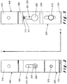
- Figures 1-3 show a device 100 according to an embodiment of the present invention in a side view, a front view and a rear view, respectively.
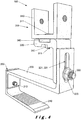
- Figures 4 and 5 show this device 100 in a perspective view in two different usage configurations of the device 100.
- the device 100 shown is intended for mounting solar panels to a base, such as for instance a slanting roof with roof tiles or other roof covering elements arranged onto supporting beams of a supporting roof structure.
- the device 100 comprises a hook-shaped lower part 200 arranged for mounting the device 100 to the roof.
- the lower part 200 comprises a first lower part portion 210 and a second lower part portion 220, which are connected to each other by means of a bolt 212 screwed through an opening arranged for that purpose through the second lower part portion 220.
- the first lower part portion 210 is slidable in relation to the second lower part portion 220 as a result of the fact that, as shown in Figure 3 , the bolt 212 is arranged in the first lower part portion 210 through an elongated slot 211 in which the bolt 212 can move up and down if the bolt 212 does not mutually secure the first lower part portion 210 and the second lower part portion 220.
- the hook shape of the lower part is used, by sliding the first lower part portion 210 underneath a supporting beam of the supporting roof structure and sliding the second lower part portion 220 over the roof covering element arranged onto the respective supporting beam.
- the height of the hook shape of the lower part 200 can be adjusted to the thickness of the supporting beam and the roof covering element by sliding the first lower part portion 210 in relation to the second lower part portion 220.
- the device 100 comprises an upper part 300 which is arranged, by means of a U-shaped mounting element 310, for mounting solar panels to the device 100.
- the upper part 300 further comprises a main body 330 by means of which the upper part 300 is connected to the lower part 200.
- the connection between the lower part 200 and the upper part 300 is realised by means of a bolt 222 and a nut 223 arranged in slots 221, 331 provided for that purpose in the second lower part portion and the main body 330, as shown in Figure 2 .
- the upper part 300 is slidable in its height direction in relation to the lower part 200 as a result of the fact that the bolt 222 can move up and down in the slots 221, 331. In this manner, the distance between the roof and solar panels mounted to the roof my means of the device 100 can be set.
- the U-shaped mounting element 310 is rotatably mounted onto the main body 330 with the opening of the U-shape facing upwards so that a mounting profile for mounting solar panels can always be slid into the mounting element 310 from the top.
- the mounting element 310 is rotatably mounted onto the main body 330 by means of a bolt 311 and a nut 312, wherein the bolt 311 is arranged through openings 313, 332 provided for that purpose in the mounting element 310.
- mounting element 310 is unrestrictedly rotatable over a full circle around the bolt 311, so that the mounting element 310 may be positioned according to any direction around the bolt 311, and be secured in that position by tightening the nut 312 onto the bolt 311.
- the upper part 300 of the device according to the embodiment shown is however further arranged for orienting the mounting element 310 according to a first preferred direction R1, as shown in Figure 4 , and a second preferred direction R2, as shown in Figure 5 .
- a first preferred direction R1 mounting profiles for mounting solar panels can be arranged in the mounting element 310 in such a way that the mounting profiles extend according to the direction transversal to the downward sloping direction of the roof, in other words: the horizontal direction.
- mounting profiles for mounting solar panels can be arranged in the mounting element 310 in such a way that the mounting profiles extend according to the downward sloping direction of the roof.
- the mounting element 310 is provided with a first engagement surface 320 and the main body 330 is provided with a second engagement surface 350.
- the first engagement surface 320 and the second engagement surface 350 face each other when the mounting element 310 is mounted onto the main body 330.
- the first engagement surface 320 and the second engagement surface 350 are further arranged in such a way that the first engagement surface 320 and the second engagement surface 350 can mutually engage according to both the first direction R1 and the second direction R2 during rotation of the mounting element 310 in relation to the main body 330.
- the first engagement surface 320 is provided with a series of protrusions 321, extending along the width direction B of the mounting element 310, and spaced at a fixed distance to each other.
- the second engagement surface 350 is provided with a first series of grooves 351 extending along the first direction R1 and a second series of grooves 352 extending along the second direction R2. Both the grooves 351 of the first series of grooves 351 and the grooves 352 of the second series of grooves 352 are at the same distance to each other as the distance between the protrusions 321 of the first engagement surface 320.
- the shape of the protrusions 321 of the first engagement surface 320 is complementary to the shape of the grooves 351 of the first series of grooves 351 of the second engagement surface 350, and complementary to the shape of the grooves 352 of the second series of grooves 352 of the second engagement surface 350.
- the protrusions 321 of the first engagement surface 320 will align with the grooves 351, 352 of the first series of grooves 351 or the second series of grooves 352 and slide into them when the mounting element 310, during rotation, is oriented according to the first direction R1 or the second direction R2, respectively.
- the user of the device 100 can quickly and without adjustments find the correct orientation of the mounting element 310 according to the first direction R1 or the first direction R2.
- the second engagement surface 350 is arranged on a separate engaging element 340 of the main body 330.
- the engaging element 340 can then be manufactured in a different way, as the engaging element 340, because of the crossing first series of grooves 351 and second series of grooves 352, is less suited for being manufactured by means of extrusion without further treatment.
- the separate engaging element 340 also allows different types of the device 100 to be provided, wherein the mounting element 310 can be oriented according to different directions for every type.
- the components of the device 100 can then be jointly manufactured, except for a modified engaging element 340 for each type of the device 100.
Landscapes
- Engineering & Computer Science (AREA)
- Chemical & Material Sciences (AREA)
- Life Sciences & Earth Sciences (AREA)
- Sustainable Development (AREA)
- Sustainable Energy (AREA)
- Thermal Sciences (AREA)
- Physics & Mathematics (AREA)
- Combustion & Propulsion (AREA)
- Mechanical Engineering (AREA)
- General Engineering & Computer Science (AREA)
- Architecture (AREA)
- Civil Engineering (AREA)
- Structural Engineering (AREA)
- Roof Covering Using Slabs Or Stiff Sheets (AREA)
Applications Claiming Priority (1)
| Application Number | Priority Date | Filing Date | Title |
|---|---|---|---|
| BE2017/5864A BE1025426B1 (nl) | 2017-11-29 | 2017-11-29 | Inrichting voor het bevestigen van zonnepanelen |
Publications (1)
| Publication Number | Publication Date |
|---|---|
| EP3493397A1 true EP3493397A1 (de) | 2019-06-05 |
Family
ID=60781410
Family Applications (1)
| Application Number | Title | Priority Date | Filing Date |
|---|---|---|---|
| EP18209118.1A Withdrawn EP3493397A1 (de) | 2017-11-29 | 2018-11-29 | Vorrichtung zur montage von solarpaneelen |
Country Status (2)
| Country | Link |
|---|---|
| EP (1) | EP3493397A1 (de) |
| BE (1) | BE1025426B1 (de) |
Cited By (13)
| Publication number | Priority date | Publication date | Assignee | Title |
|---|---|---|---|---|
| CN110460298A (zh) * | 2019-06-28 | 2019-11-15 | 常州中信博新能源科技有限公司 | 可调式太阳能光伏支架 |
| CN110762860A (zh) * | 2019-09-27 | 2020-02-07 | 海宁双丰科技股份有限公司 | 一种太阳能水箱的连接座及其安装方法 |
| DE102020100144A1 (de) * | 2019-12-20 | 2021-06-24 | Jing-Xin Solar Ltd. | Montagevorrichtung für einen trägeraufbau |
| BE1028428B1 (nl) * | 2020-06-24 | 2022-02-01 | Batimont Bvba | Inrichting voor bevestiging van een montagerail op een zadeldak |
| EP4148980A1 (de) * | 2021-09-13 | 2023-03-15 | BluBase B.V. | Dachhaken |
| EP4227599A1 (de) * | 2022-02-14 | 2023-08-16 | Van Der Valk Systemen B.V. | Befestigungsvorrichtung, dachhaken und verfahren zur befestigung einer montageschiene auf einem dach |
| IT202200011399A1 (it) * | 2022-05-30 | 2023-11-30 | Basic Soc A Responsabilita Limitata Soc Benefit | Impianto fotovoltaico |
| BE1030183B1 (de) * | 2023-05-25 | 2024-05-15 | Shanghai Chiko Solar Tech | Vollaluminiumhaken für eine photovoltaische Solarhalterung |
| EP4553403A1 (de) * | 2023-11-13 | 2025-05-14 | SL Rack GmbH | Dachhaken |
| EP4553404A1 (de) * | 2023-11-13 | 2025-05-14 | SL Rack GmbH | Dachhaken |
| DE102024139919A1 (de) * | 2023-12-30 | 2025-07-03 | Jochen Deicke | Universeller Montagehaken für Photovoltaik-Trägersysteme |
| DE102024103099A1 (de) * | 2024-02-05 | 2025-08-07 | IIS Asset Management GmbH | Halterungsvorrichtung und System für Solarpanele |
| BE1032310B1 (nl) * | 2023-12-29 | 2025-08-12 | Eco4Everyone | Dakhaak |
Citations (6)
| Publication number | Priority date | Publication date | Assignee | Title |
|---|---|---|---|---|
| DE19811399A1 (de) * | 1998-03-16 | 1999-09-23 | Dachziegelwerke Pfleiderer Gmb | Anordnung zur Dachbefestigung von Solarmodulen |
| WO2006101392A2 (en) | 2005-02-23 | 2006-09-28 | Girasol International B.V. | Device and method for fixing objects, in particular solar panels, to a roof |
| DE102005018687B3 (de) * | 2005-04-20 | 2006-11-16 | Oskar Fleck | An einem Dacheindeckungselement angebrachte Halterung zur lösbaren Befestigung eines Gegenstandes, insbesondere eines Solarmoduls |
| US20120152326A1 (en) * | 2010-12-13 | 2012-06-21 | John Raymond West | Discrete Attachment Point Apparatus and System for Photovoltaic Arrays |
| EP2733439A2 (de) * | 2012-07-20 | 2014-05-21 | Marc Crombez | Kit, System und Verfahren zum Befestigen von Solarmodulen |
| US20170229997A1 (en) * | 2016-02-10 | 2017-08-10 | Precision Tech Welding & Machine Inc. | Solar panel mounting system with adjustment features |
-
2017
- 2017-11-29 BE BE2017/5864A patent/BE1025426B1/nl not_active IP Right Cessation
-
2018
- 2018-11-29 EP EP18209118.1A patent/EP3493397A1/de not_active Withdrawn
Patent Citations (6)
| Publication number | Priority date | Publication date | Assignee | Title |
|---|---|---|---|---|
| DE19811399A1 (de) * | 1998-03-16 | 1999-09-23 | Dachziegelwerke Pfleiderer Gmb | Anordnung zur Dachbefestigung von Solarmodulen |
| WO2006101392A2 (en) | 2005-02-23 | 2006-09-28 | Girasol International B.V. | Device and method for fixing objects, in particular solar panels, to a roof |
| DE102005018687B3 (de) * | 2005-04-20 | 2006-11-16 | Oskar Fleck | An einem Dacheindeckungselement angebrachte Halterung zur lösbaren Befestigung eines Gegenstandes, insbesondere eines Solarmoduls |
| US20120152326A1 (en) * | 2010-12-13 | 2012-06-21 | John Raymond West | Discrete Attachment Point Apparatus and System for Photovoltaic Arrays |
| EP2733439A2 (de) * | 2012-07-20 | 2014-05-21 | Marc Crombez | Kit, System und Verfahren zum Befestigen von Solarmodulen |
| US20170229997A1 (en) * | 2016-02-10 | 2017-08-10 | Precision Tech Welding & Machine Inc. | Solar panel mounting system with adjustment features |
Cited By (18)
| Publication number | Priority date | Publication date | Assignee | Title |
|---|---|---|---|---|
| CN110460298A (zh) * | 2019-06-28 | 2019-11-15 | 常州中信博新能源科技有限公司 | 可调式太阳能光伏支架 |
| CN110762860A (zh) * | 2019-09-27 | 2020-02-07 | 海宁双丰科技股份有限公司 | 一种太阳能水箱的连接座及其安装方法 |
| DE102020100144A1 (de) * | 2019-12-20 | 2021-06-24 | Jing-Xin Solar Ltd. | Montagevorrichtung für einen trägeraufbau |
| DE102020100144B4 (de) | 2019-12-20 | 2022-02-17 | Jing-Xin Solar Ltd. | Montagevorrichtung für einen trägeraufbau |
| BE1028428B1 (nl) * | 2020-06-24 | 2022-02-01 | Batimont Bvba | Inrichting voor bevestiging van een montagerail op een zadeldak |
| EP4148980A1 (de) * | 2021-09-13 | 2023-03-15 | BluBase B.V. | Dachhaken |
| NL2029180B1 (nl) * | 2021-09-13 | 2023-03-23 | Kwws B V | Dakpanhaak |
| NL2030923B1 (nl) * | 2022-02-14 | 2023-08-18 | Van Der Valk Systemen B V | Bevestigingsinrichting, dakhaak, montagerail en werkwijze voor de bevestiging van objecten op een dak |
| EP4227599A1 (de) * | 2022-02-14 | 2023-08-16 | Van Der Valk Systemen B.V. | Befestigungsvorrichtung, dachhaken und verfahren zur befestigung einer montageschiene auf einem dach |
| IT202200011399A1 (it) * | 2022-05-30 | 2023-11-30 | Basic Soc A Responsabilita Limitata Soc Benefit | Impianto fotovoltaico |
| WO2023233211A1 (en) * | 2022-05-30 | 2023-12-07 | Basic Societa' A Responsabilita' Limitata Societa' Benefit | Photovoltaic system |
| BE1030183B1 (de) * | 2023-05-25 | 2024-05-15 | Shanghai Chiko Solar Tech | Vollaluminiumhaken für eine photovoltaische Solarhalterung |
| EP4553403A1 (de) * | 2023-11-13 | 2025-05-14 | SL Rack GmbH | Dachhaken |
| EP4553404A1 (de) * | 2023-11-13 | 2025-05-14 | SL Rack GmbH | Dachhaken |
| DE102023131546A1 (de) * | 2023-11-13 | 2025-05-15 | Sl Rack Gmbh | Dachhaken |
| BE1032310B1 (nl) * | 2023-12-29 | 2025-08-12 | Eco4Everyone | Dakhaak |
| DE102024139919A1 (de) * | 2023-12-30 | 2025-07-03 | Jochen Deicke | Universeller Montagehaken für Photovoltaik-Trägersysteme |
| DE102024103099A1 (de) * | 2024-02-05 | 2025-08-07 | IIS Asset Management GmbH | Halterungsvorrichtung und System für Solarpanele |
Also Published As
| Publication number | Publication date |
|---|---|
| BE1025426B1 (nl) | 2019-02-13 |
Similar Documents
| Publication | Publication Date | Title |
|---|---|---|
| BE1025426B1 (nl) | Inrichting voor het bevestigen van zonnepanelen | |
| US8806815B1 (en) | Adjustable solar panel tile roof mounting device | |
| EP3020884B1 (de) | Vorgehängte Fassadenkonstruktion | |
| EP2896764B1 (de) | System zur Halterung von Geländerplatten und Verfahren zur Einstellung der Vertikalneigung von Geländerplatten | |
| DE202015102936U1 (de) | Photovoltaikmodul-Montagebügel sowie Photovoltaiksystem | |
| EP2385323A2 (de) | Gestell zur Befestigung von Solarmodulen | |
| KR101479908B1 (ko) | 태양광 패널용 설치 구조물 | |
| WO2015042260A1 (en) | Low slope mounted photovoltaic array | |
| EP2031324A2 (de) | Solareinrichtung | |
| EP3176343A1 (de) | Befestigungsklammer für dachausrüstung | |
| DE102005043957C5 (de) | Dachhaken zur Montage von Solaranlagenmodulen auf Dächern | |
| DE3130471C2 (de) | Spiegelanordnung zum Reflektieren und Konzentrieren von Strahlungsenergie | |
| DE102016007268A1 (de) | Vorrichtungen und Verfahren zur Einstellung der Vertikalneigung von Geländerplatten | |
| WO2013110387A1 (de) | Halte- und spannvorrichtung für flexible, flächige güter | |
| DE202005004236U1 (de) | Halterung für Solarmodule am Dach | |
| DK2937491T3 (en) | Balancing device for an overlying structure | |
| EP0268125B1 (de) | Vorrichtung zum Halten einer Parabolantenne | |
| DE202015104529U1 (de) | Pflanzenkastenhalter | |
| EP3176344A1 (de) | First- oder gratlattenanordnung | |
| EP0662291B1 (de) | Trägersystem | |
| EP3090653B1 (de) | Regal | |
| EP1512344A1 (de) | Lagerbock für Fässer | |
| DE102004023878A1 (de) | Dachzubehörstütze | |
| EP1063707A3 (de) | Solarzellenanordnung | |
| EP2674987A1 (de) | Modulträger für Solarmodule sowie Anordnung mit mehreren Modulträgern |
Legal Events
| Date | Code | Title | Description |
|---|---|---|---|
| PUAI | Public reference made under article 153(3) epc to a published international application that has entered the european phase |
Free format text: ORIGINAL CODE: 0009012 |
|
| STAA | Information on the status of an ep patent application or granted ep patent |
Free format text: STATUS: THE APPLICATION HAS BEEN PUBLISHED |
|
| AK | Designated contracting states |
Kind code of ref document: A1 Designated state(s): AL AT BE BG CH CY CZ DE DK EE ES FI FR GB GR HR HU IE IS IT LI LT LU LV MC MK MT NL NO PL PT RO RS SE SI SK SM TR |
|
| AX | Request for extension of the european patent |
Extension state: BA ME |
|
| STAA | Information on the status of an ep patent application or granted ep patent |
Free format text: STATUS: REQUEST FOR EXAMINATION WAS MADE |
|
| 17P | Request for examination filed |
Effective date: 20191203 |
|
| RBV | Designated contracting states (corrected) |
Designated state(s): AL AT BE BG CH CY CZ DE DK EE ES FI FR GB GR HR HU IE IS IT LI LT LU LV MC MK MT NL NO PL PT RO RS SE SI SK SM TR |
|
| STAA | Information on the status of an ep patent application or granted ep patent |
Free format text: STATUS: EXAMINATION IS IN PROGRESS |
|
| 17Q | First examination report despatched |
Effective date: 20210629 |
|
| STAA | Information on the status of an ep patent application or granted ep patent |
Free format text: STATUS: THE APPLICATION HAS BEEN WITHDRAWN |
|
| 18W | Application withdrawn |
Effective date: 20211021 |