EP3494381B1 - Absorptionskavität mit eingangs- und ausgangswellenleitern für einen biologischen oder chemischen sensor - Google Patents
Absorptionskavität mit eingangs- und ausgangswellenleitern für einen biologischen oder chemischen sensor Download PDFInfo
- Publication number
- EP3494381B1 EP3494381B1 EP17765222.9A EP17765222A EP3494381B1 EP 3494381 B1 EP3494381 B1 EP 3494381B1 EP 17765222 A EP17765222 A EP 17765222A EP 3494381 B1 EP3494381 B1 EP 3494381B1
- Authority
- EP
- European Patent Office
- Prior art keywords
- waveguide
- absorption cavity
- injection
- extraction
- cavity
- Prior art date
- Legal status (The legal status is an assumption and is not a legal conclusion. Google has not performed a legal analysis and makes no representation as to the accuracy of the status listed.)
- Active
Links
- 238000010521 absorption reaction Methods 0.000 title claims description 134
- 239000000126 substance Substances 0.000 title claims description 20
- 238000002347 injection Methods 0.000 claims description 70
- 239000007924 injection Substances 0.000 claims description 70
- 238000000605 extraction Methods 0.000 claims description 64
- 238000004458 analytical method Methods 0.000 claims description 45
- 230000003287 optical effect Effects 0.000 claims description 23
- 230000008878 coupling Effects 0.000 claims description 12
- 238000010168 coupling process Methods 0.000 claims description 12
- 238000005859 coupling reaction Methods 0.000 claims description 12
- 238000005253 cladding Methods 0.000 claims description 4
- NCGICGYLBXGBGN-UHFFFAOYSA-N 3-morpholin-4-yl-1-oxa-3-azonia-2-azanidacyclopent-3-en-5-imine;hydrochloride Chemical compound Cl.[N-]1OC(=N)C=[N+]1N1CCOCC1 NCGICGYLBXGBGN-UHFFFAOYSA-N 0.000 claims description 2
- 238000009432 framing Methods 0.000 claims 1
- 230000006978 adaptation Effects 0.000 description 16
- 238000005259 measurement Methods 0.000 description 15
- 230000035945 sensitivity Effects 0.000 description 13
- 239000000758 substrate Substances 0.000 description 13
- XUIMIQQOPSSXEZ-UHFFFAOYSA-N Silicon Chemical compound [Si] XUIMIQQOPSSXEZ-UHFFFAOYSA-N 0.000 description 10
- 239000010703 silicon Substances 0.000 description 10
- 229910052710 silicon Inorganic materials 0.000 description 9
- PCHJSUWPFVWCPO-UHFFFAOYSA-N gold Chemical compound [Au] PCHJSUWPFVWCPO-UHFFFAOYSA-N 0.000 description 7
- 239000010931 gold Substances 0.000 description 7
- 229910052737 gold Inorganic materials 0.000 description 7
- 230000005540 biological transmission Effects 0.000 description 5
- GNPVGFCGXDBREM-UHFFFAOYSA-N germanium atom Chemical group [Ge] GNPVGFCGXDBREM-UHFFFAOYSA-N 0.000 description 5
- 239000007788 liquid Substances 0.000 description 5
- 229910000927 Ge alloy Inorganic materials 0.000 description 4
- 229910000676 Si alloy Inorganic materials 0.000 description 4
- 238000013459 approach Methods 0.000 description 4
- 239000011248 coating agent Substances 0.000 description 4
- 238000000576 coating method Methods 0.000 description 4
- 230000007423 decrease Effects 0.000 description 4
- 230000010354 integration Effects 0.000 description 4
- VYPSYNLAJGMNEJ-UHFFFAOYSA-N Silicium dioxide Chemical compound O=[Si]=O VYPSYNLAJGMNEJ-UHFFFAOYSA-N 0.000 description 3
- 239000002245 particle Substances 0.000 description 3
- 230000001902 propagating effect Effects 0.000 description 3
- 230000002745 absorbent Effects 0.000 description 2
- 239000002250 absorbent Substances 0.000 description 2
- 238000001514 detection method Methods 0.000 description 2
- 235000021183 entrée Nutrition 0.000 description 2
- 238000000407 epitaxy Methods 0.000 description 2
- 238000004519 manufacturing process Methods 0.000 description 2
- 230000010363 phase shift Effects 0.000 description 2
- 229920000297 Rayon Polymers 0.000 description 1
- 229910052581 Si3N4 Inorganic materials 0.000 description 1
- 229910004298 SiO 2 Inorganic materials 0.000 description 1
- 229910045601 alloy Inorganic materials 0.000 description 1
- 239000000956 alloy Substances 0.000 description 1
- 238000009412 basement excavation Methods 0.000 description 1
- 238000003486 chemical etching Methods 0.000 description 1
- 230000001186 cumulative effect Effects 0.000 description 1
- 230000003247 decreasing effect Effects 0.000 description 1
- 230000001419 dependent effect Effects 0.000 description 1
- 238000009792 diffusion process Methods 0.000 description 1
- 238000005530 etching Methods 0.000 description 1
- 238000011049 filling Methods 0.000 description 1
- 238000001914 filtration Methods 0.000 description 1
- 229910052732 germanium Inorganic materials 0.000 description 1
- 238000005304 joining Methods 0.000 description 1
- 239000000463 material Substances 0.000 description 1
- 238000000034 method Methods 0.000 description 1
- 230000000644 propagated effect Effects 0.000 description 1
- 230000005855 radiation Effects 0.000 description 1
- 239000002964 rayon Substances 0.000 description 1
- 239000000377 silicon dioxide Substances 0.000 description 1
- HQVNEWCFYHHQES-UHFFFAOYSA-N silicon nitride Chemical compound N12[Si]34N5[Si]62N3[Si]51N64 HQVNEWCFYHHQES-UHFFFAOYSA-N 0.000 description 1
- 239000000243 solution Substances 0.000 description 1
- 230000003595 spectral effect Effects 0.000 description 1
- 238000011144 upstream manufacturing Methods 0.000 description 1
Images



Classifications
-
- G—PHYSICS
- G01—MEASURING; TESTING
- G01N—INVESTIGATING OR ANALYSING MATERIALS BY DETERMINING THEIR CHEMICAL OR PHYSICAL PROPERTIES
- G01N21/00—Investigating or analysing materials by the use of optical means, i.e. using sub-millimetre waves, infrared, visible or ultraviolet light
- G01N21/01—Arrangements or apparatus for facilitating the optical investigation
-
- G—PHYSICS
- G01—MEASURING; TESTING
- G01N—INVESTIGATING OR ANALYSING MATERIALS BY DETERMINING THEIR CHEMICAL OR PHYSICAL PROPERTIES
- G01N21/00—Investigating or analysing materials by the use of optical means, i.e. using sub-millimetre waves, infrared, visible or ultraviolet light
- G01N21/01—Arrangements or apparatus for facilitating the optical investigation
- G01N21/03—Cuvette constructions
- G01N21/031—Multipass arrangements
-
- G—PHYSICS
- G01—MEASURING; TESTING
- G01N—INVESTIGATING OR ANALYSING MATERIALS BY DETERMINING THEIR CHEMICAL OR PHYSICAL PROPERTIES
- G01N21/00—Investigating or analysing materials by the use of optical means, i.e. using sub-millimetre waves, infrared, visible or ultraviolet light
- G01N21/17—Systems in which incident light is modified in accordance with the properties of the material investigated
- G01N21/25—Colour; Spectral properties, i.e. comparison of effect of material on the light at two or more different wavelengths or wavelength bands
- G01N21/31—Investigating relative effect of material at wavelengths characteristic of specific elements or molecules, e.g. atomic absorption spectrometry
- G01N21/35—Investigating relative effect of material at wavelengths characteristic of specific elements or molecules, e.g. atomic absorption spectrometry using infrared light
- G01N21/3504—Investigating relative effect of material at wavelengths characteristic of specific elements or molecules, e.g. atomic absorption spectrometry using infrared light for analysing gases, e.g. multi-gas analysis
-
- G—PHYSICS
- G01—MEASURING; TESTING
- G01N—INVESTIGATING OR ANALYSING MATERIALS BY DETERMINING THEIR CHEMICAL OR PHYSICAL PROPERTIES
- G01N21/00—Investigating or analysing materials by the use of optical means, i.e. using sub-millimetre waves, infrared, visible or ultraviolet light
- G01N21/01—Arrangements or apparatus for facilitating the optical investigation
- G01N21/03—Cuvette constructions
- G01N2021/0378—Shapes
-
- G—PHYSICS
- G01—MEASURING; TESTING
- G01N—INVESTIGATING OR ANALYSING MATERIALS BY DETERMINING THEIR CHEMICAL OR PHYSICAL PROPERTIES
- G01N2201/00—Features of devices classified in G01N21/00
- G01N2201/08—Optical fibres; light guides
Definitions
- the invention relates to the field of biological or chemical sensors, in particular gas concentration sensors.
- the invention relates more particularly to sensors comprising a cavity intended to receive a biological or chemical medium, in which an analysis beam is partially absorbed.
- Chemical sensors of the gas sensor type are known in the prior art, comprising a so-called absorption cavity, the internal walls of which are provided with a reflective coating.
- the absorption cavity has openings on the outside, so that it fills with the surrounding gaseous medium.
- a light source for the emission of a so-called analysis light beam
- a photo-detector for the detection of a measurement beam corresponding to the light beam. analysis after partial absorption by the gas inside the cavity.
- the absorption cavity has for example an ellipse shape, with the light source placed in a first focus of the ellipse, and the photo-detector placed in a second focus of the ellipse.
- the analysis beam emitted by the light source propagates in the cavity, is reflected on a reflecting wall thereof, and returns to the photo-detector. The analysis beam thus makes two passages in the cavity.
- the variation in light intensity I r I 0 thus makes it possible to measure a gas concentration.
- one solution consists in increasing the distance r traveled by the analysis beam in the cavity.
- the document EP 2 891876 describes for example an absorption cavity made up of a plane mirror and a spherical mirror.
- JP S63 304137 which describes an absorption cavity delimited by a concave paraboloid mirror.
- An objective of the present invention is to provide an optical device with absorption cavity, for a chemical or biological sensor such as a gas sensor, making it possible to further increase the sensitivity of the sensor.
- the measurement beam corresponds to the analysis beam at the output of the absorption cavity, that is to say after it has passed through the absorption cavity.
- the light source emitting the analysis beam is offset outside the cavity.
- the photo-detector is deported outside the cavity.
- the invention therefore makes it possible to simplify the integration of the light source and the photo-detector into a sensor with an absorption cavity.
- This simplified integration can make it possible to improve positioning and alignment precision of the light source and of the photo-detector, and therefore to improve the sensitivity of said sensor.
- the invention also makes it possible to exploit the possibilities of guided optics to process the analysis beam before it enters the absorption cavity and / or the measurement beam leaving the absorption cavity (spectral filtering, routing , etc.).
- the invention is particularly clever in that it overcomes the prejudices of those skilled in the art by proposing a new track for improving the sensitivity not based on a new form of the absorption cavity.
- the figure 1A is a sectional view, in the plane (xOy) of an orthonormal reference frame.
- the figure 1B is a sectional view, in the plane (yOz) of said reference.
- figure 1A is a top view in transparency
- figure 1B a side view in transparency
- the optical device 100 comprises an absorption cavity 110, an injection wave guide 120 and an extraction wave guide 130.
- the optical device 100 is advantageously formed in a substrate 140, for example a silicon substrate.
- the absorption cavity 110 is intended to receive a gaseous or even liquid medium, which will partly absorb an analysis light beam, the absorption being characteristic of a chemical or biological element and of the concentration of this element.
- the absorption cavity 110 here has the shape of a straight cylinder, the base of which is a half-ellipse.
- the base is parallel to the plane (xOy) (see figure 1A ).
- the generator of the cylinder is parallel to the axis (Oz).
- the height h of the cavity is therefore measured along this axis (Oz).
- the internal walls of the absorption cavity 110 are at least partially covered with a reflective coating 111, here a thin layer of gold.
- the reflective coating 111 extends in particular over an upper planar wall, a lower planar wall, and a rounded side wall of the cavity 110.
- the injection waveguide 120 is configured to guide an analysis beam 150 from the outside of the absorption cavity 110, as far as the entry thereof.
- the injection waveguide 120 has a first end 121 arranged in a first focal point F1 of the ellipse defining the absorption cavity.
- the center of the injection waveguide 120 at its end situated on the side of the absorption cavity 110, coincides with the focal point F1.
- the injection waveguide 120 here extends entirely outside the absorption cavity 110.
- the height of the injection waveguide 120 is less than that of the absorption cavity (dimension along the axis (Oz)), for example at least two times less.
- the extraction waveguide 130 is configured to guide a measurement beam 160 to the outside of the absorption cavity 110.
- the extraction waveguide 130 has a first end 131 arranged in a second focal point F2 of the ellipse defining the absorption cavity.
- the center of the extraction waveguide 130 at its end situated on the side of the absorption cavity 110, coincides with the focal point F2.
- the extraction waveguide 130 here extends entirely outside the absorption cavity 110.
- the height of the extraction waveguide 130 is less than that of the absorption cavity, for example at least two times less.
- the chemical or biological sensor 1000 comprises the optical device 100, a light source 1200 and a photo-detector 1300.
- the light source 1200 is arranged here at a second end 122 of the injection waveguide 120.
- QCL quantum cascade laser source
- NDIR non-dispersive infrared source
- the light source 1200 emits the analysis beam 150, which propagates in the injection waveguide until it enters the absorption cavity 110.
- the analysis beam 150 crosses the absorption cavity for the first time starting from the first focal point F1 of the ellipse, is reflected on the reflective coating 111 inside of the absorption cavity, and crosses the absorption cavity a second time until reaching the second focal point F2 of the ellipse and entering the extraction waveguide 130.
- the analysis beam is partially absorbed by the gaseous or liquid medium filling the absorption cavity.
- measurement beam 160 is used to mean the analysis beam at its output from the absorption cavity, at the input of the extraction waveguide, here at the second focal point F2 of the ellipse.
- the photo-detector 1300 is arranged here at a second end 132 of the extraction waveguide 130.
- thermopile for example an infrared detector, of the bolometric or pyroelectric type, or thermopile.
- the optical device according to the invention allows the light source for emitting the analysis beam, and the photo-detector for receiving the measurement beam, to be placed outside the absorption cavity. Their integration is therefore facilitated.
- the central wavelength of the analysis beam depends on the nature of the chemical or biological species to be detected.
- the materials constituting the injection waveguide 120 and the extraction waveguide 130 are adapted to said central wavelength.
- the injection waveguides 120 and extraction 130 preferably comprise a germanium core, or an alloy of silicon and germanium, and a sheath of silicon, or an alloy of silicon and germanium.
- the injection waveguides 120 and extraction 130 preferably comprise a core of silicon (Si) and a cladding in silica (SiO 2 ).
- the injection waveguides 120 and extraction 130 preferably comprise a core made of silicon nitride (Si 3 N 4 ) and a silica sheath (SiO 2 ).
- a visible analysis beam can be used to detect a biological species, preferably in a liquid medium, or for particle detection.
- the light source 1200 is integrated in the same substrate as the optical device 100.
- the light source 1200 is for example a thermal source as described in the application for patent FR 2 974 423 , emitting infrared radiation.
- the light source 1200 may be a quantum cascade laser source.
- the photo-detector 1300 is advantageously integrated in the same substrate as the optical device 100.
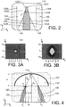
- the figure 2 schematically illustrates a detail of the injection waveguide 120, on the side of the absorption cavity 110.
- the extraction waveguide 130 has the same structure.
- the injection waveguide 120 comprises a core 123, and a so-called main sheath 124 formed here by a portion of the substrate 140 (see figure 1A ).
- the injection waveguide 120 At its end situated on the side of the absorption cavity, the injection waveguide 120 is said to be "at a point". In other words, this end is refined, on the side of the absorption cavity.
- the heart 123 has a pointed shape.
- the heart 123 has a constant height.
- the end of the tip has a square or rectangular section, defined by two third walls 123C parallel to each other, the spacing of which corresponds to the minimum spacing of the two second walls 123B.
- This square or rectangular end allows better control of the minimum width of the core 123.
- the injection waveguide 120 also has a so-called adaptation region 125.
- the adaptation region 125 also has a constant height according to the generator of the cylinder.
- the adaptation region 125 frames a decreasing width of the sheath 124, then frames the walls 123B and 123C in the shape of a point of the heart 123, by being in direct physical contact with them.
- the adaptation region 125 has a section whose width gradually increases as one approaches the absorption cavity 110, so that the width of the sheath 124 gradually decreases until it disappears entirely, then the width of the heart gradually decreases until it reaches a final width.
- the refraction index of the adaptation region 125 is lower than the refraction index of the sheath 124, and therefore a fortiori than the refraction index of the heart 123.
- the tip end of the injection waveguide 120 therefore causes a gradual reduction in the effective index of the mode guided by the injection waveguide, as one approaches the absorption cavity 110.
- the vertical dimension of said guided mode, along an axis parallel to the generatrix of the cylinder, gradually increases.
- the vertical dimension of the mode guided in said waveguide is substantially equal to the height of the cavity, that is to say to the vertical dimension of the fundamental mode of the cavity.
- the ratio between the vertical dimension of the mode guided in the waveguide and the height of the absorption cavity is for example between 0.75 and 1.25.
- a mode vertical size adaptation is thus carried out (where the vertical is the generator of the right cylinder), between the fundamental mode of the absorption cavity 110 and the mode guided in the injection waveguide.
- the extraction waveguide 130 likewise performs a vertical mode size adaptation between the fundamental mode of the absorption cavity 110 and the mode guided in the extraction waveguide.
- the vertical dimension of the mode guided in said waveguide is substantially equal to the vertical dimension of the fundamental mode of the cavity, and gradually decreases as and when one moves away from the absorption cavity.
- the mode adaptation is not necessary in the planes parallel to the base of the cylinder, since in these planes, the elliptical shape of the absorption cavity 110 ensures the convergence of the light rays from the injection waveguide towards the extraction waveguide.
- the adaptation region 125 is constituted by at least one housing, or excavation, or secondary cavity, hollowed out in the substrate, and open (e) on the absorption cavity 110.
- Said housing is therefore filled with the same gaseous or liquid medium as the absorption cavity 110, which makes it possible to optimize the mode adaptation between the injection and extraction waveguides, and the absorption cavity.
- the adaptation region 125 is formed more particularly by two housings, arranged on either side of the heart 123.
- phase constant ⁇ depends on the wavelength and the mode of the light beam propagating in the waveguide, as well as on the properties of this waveguide (in particular refractive indices and geometry).
- the effective index designates the average optical index of the medium as it is "seen" by a mode of the light beam propagating in the waveguide.
- FIGS. 3A and 3B illustrate the mode adaptation implemented in the waveguide shown in figure 2 .
- the core 123 has a constant height of 3 ⁇ m, and a maximum width of 2 ⁇ m. It is made of an alloy of silicon and germanium, and has a refractive index equal to 3.6.
- the sheath 124 is made of silicon, with a refractive index equal to 3.4.
- the central wavelength of the analysis beam is 4.26 ⁇ m.
- the absorption cavity has a height of 25 ⁇ m, defining the vertical size of the fundamental mode in said cavity.
- the abscissa axis is graduated in ⁇ m, and corresponds to a dimension along the axis (Ox) (axis of the width of the absorbent cavity).
- the ordinate axis is graduated in ⁇ m, and corresponds to a dimension along the axis (Oz) (vertical axis, or axis of the height of the absorbent cavity).
- the figure 3A represents the size of the guided mode, at a position in the waveguide of injection, respectively of extraction, where the width of the heart 123 is 1 ⁇ m.
- the guided mode has a dimension along the axis (Oz) equal to approximately 5 ⁇ m.
- the figure 3B represents the size of the guided mode, at a position in the waveguide of injection, respectively of extraction, where the width of the heart 123 is 0.1 ⁇ m.
- the guided mode has a dimension along the axis (Oz) equal to approximately 20 ⁇ m.
- the pointed shape of the end of the injection waveguide, respectively extraction therefore allows a vertical mode adaptation, between the mode guided in the injection waveguide, respectively extraction , and the fundamental mode of the absorption cavity.
- the figure 4 illustrates a variant of the optical device shown in Figures 1A and 1B .
- the central axis 126 'of the injection waveguide 120' is inclined by an angle ⁇ 1 relative to a plane of symmetry 112 'of the absorption cavity 110'.
- the plane of symmetry 112 ′ is a vertical plane parallel to the axis (Oz), and passing through one of the minor axis or the major axis of the ellipse, here the minor axis.
- the angle ⁇ 1 corresponds substantially to the angle of incidence of a light beam reaching the absorption cavity 110 ', such that the corresponding refracted ray propagates inside the absorption cavity up to l 'intersection between the plane of symmetry 112' and the elliptical wall of said cavity.
- substantially equal it is preferably meant equal to plus or minus 1 ° near, or even to plus or minus 2 ° near.
- the angle ⁇ 1 is exactly equal to ⁇ i .
- the angle ⁇ 1 is for example greater than or equal to 3 °, or even greater than or equal to 5 ° or even more, in absolute value.
- the angle ⁇ 1 is such that the central axis 126 'of the injection waveguide is inclined towards the plane of symmetry 112' of the absorption cavity.
- the injection waveguide 120 'and the extraction waveguide 130' are symmetrical to each other relative to the plane of symmetry 112 '.
- This inclination of the injection and extraction waveguides, towards the plane of symmetry 112 ′ of the absorption cavity, allows the central radius of the analysis beam to propagate from the injection waveguide towards the bottom of the absorption cavity, and from the bottom of the absorption cavity to the extraction waveguide.
- the distance between the respective ends of the injection and extraction waveguides, on the side of the cavity absorption, is high enough to avoid any evanescent coupling between these two guides. In other words, it is a question of avoiding that a guided mode at the output of the injection waveguide interferes with a guided mode at the input of the extraction waveguide.
- This distance is preferably measured between the center of the injection waveguide and the center of the extraction waveguide, at their ends located on the side of the absorption cavity.
- ⁇ x ⁇ w is chosen, with w the width of the guided mode at the output of the injection waveguide, respectively at the input of the extraction waveguide, projected onto the axis (Ox).
- the axis (Ox) is the axis joining the center of the injection waveguide and the center of the extraction waveguide, at their ends located on the side of the absorption cavity.
- the width of the guided mode at the output of the injection waveguide, respectively at the input of the extraction waveguide is a width at 1 / e 2 in intensity, for a Gaussian guided mode.
- the width of the guided mode is preferably measured in a plane orthogonal to the central axis of the injection waveguide, respectively of the extraction waveguide.
- This width is measured in particular along an axis corresponding to the intersection between such a plane, and a plane parallel to the base of the cylinder (cylinder defining the shape of the absorption cavity).
- the width of the guided mode can be used directly at the output of the injection waveguide, respectively at the input of the extraction waveguide .
- ⁇ x greater than or equal to 5 ⁇ m, and even greater than or equal to 10 ⁇ m.
- the figure 5 illustrates schematically a second embodiment of an optical device 500 and a chemical or biological sensor 5000 according to the invention.
- the injection waveguide 520 and the extraction waveguide 530 are connected together by a so-called loopback waveguide 570.
- the injection waveguide 520, the extraction waveguide 530 and the loopback waveguide 570 together form a single curved waveguide.
- the curved waveguide and the absorption cavity are arranged together to guide the light in a loop path. They are said to form a loop together.
- the curved waveguide is adapted so that the phase shift provided by a revolution in said loop, at a wavelength of interest of the analysis beam, is a multiple of 2 ⁇ .
- said loop is resonant at a wavelength of interest of the analysis beam. This resonance is for example obtained by an adequate choice of the curvilinear length of the curved waveguide.
- this curved waveguide extends between the first focal point F1 and the second focal point F2 of the ellipse, on the side opposite to the elliptical wall of the resonant cavity 510.
- This curved waveguide is coupled to a so-called main waveguide 580, by evanescent coupling.
- a guided mode of the main waveguide interferes with a guided mode of the curved waveguide, which results in a transfer of energy between these two modes.
- the main waveguide 580 here extends in a straight line, parallel to a tangent to the curved waveguide, in particular a tangent to the loopback waveguide 570.
- the main waveguide 580 and the curved waveguide Preferably, but not limited to, there is no direct physical contact between the main waveguide 580 and the curved waveguide, the distance between these two guides being adapted to the establishment of said evanescent coupling. .
- At one end of the main waveguide 580 is the light source 5200, while at the other end of the main waveguide 580 is the photodetector 5300.
- the analysis beam emitted by the light source 5200 propagates in the main wave guide 580, up to a point of coupling with the curved wave guide where it is at least partially transferred into the guide d curved wave.
- the analysis beam then performs several turns in a loop constituted by the injection waveguide 520, the absorption cavity 510, the extraction waveguide 530, and the loopback waveguide 570 .
- the analysis beam thus makes several passages in the absorption cavity 510.
- the analysis beam returning in the main waveguide 580 forms the measurement beam according to the invention, which propagates in the main waveguide 580 to the photo-detector 5300.
- This embodiment makes it possible to greatly increase the cumulative length of the path of the analysis beam in the absorption cavity 510, without harming the compactness of the optical device 500 and of the sensor 5000 according to the invention.
- the transmission rate ⁇ with gas and the transmission rate ⁇ without gas are compared, as a function of K.
- the distance between the main waveguide and the curved waveguide is less than ⁇ .
- K 0.3 and 0.5, which determines an optimal distance between the main waveguide and the curved waveguide.
- the sensitivity of the sensor according to the invention having the above characteristics is then calculated for different CO 2 concentrations.
- This sensitivity corresponds to the ratio between the light intensity measured by the photo-detector in the absence of gas, and in the presence of gas at said concentration.
- This sensitivity is compared to that of a sensor according to the prior art, the absorption cavity of which has the same dimensions.
- the gain in sensitivity is multiplied by a factor approximately equal to 4.
- the figure 6 illustrates an advantageous variant of the embodiment of the figure 5 .
- the optical device 600 and the sensor 6000 according to this variant do not differ from the embodiment illustrated in figure 5 , that in that the injection waveguide 620, the extraction waveguide 630 and the loopback waveguide 670 together form a single curved waveguide, which extends between the first focus F1 and the second focus F2 of the ellipse, passing through the rear of the cavity.
- the curved waveguide partially surrounds the absorption cavity 610, extending from the side of the cavity 610 opposite the side receiving the respective ends of the injection waveguide 620 and the extraction waveguide 630.
- the additional advantage conferred by this variant is a lesser curvature of the curved waveguide. This minimizes optical losses in the curved waveguide, in particular losses to radiative modes.
- the figure 7 schematically illustrates an example of a method of manufacturing an optical device according to the invention.
- the figures on the right represent the device in progress, according to sectional views in a plane parallel to the plane (xOy) of the coordinate system defined above.
- a substrate 71 here a silicon substrate (starting point 701).
- a layer of silicon and germanium alloy is deposited by epitaxy on the substrate 71, which is etched to form two ribbons 72.
- a ribbon will form the injection waveguide, while the other ribbon will form the extraction waveguide.
- the alloy comprises for example 40% germanium.
- the substrate 71 and the ribbons 72 are then covered with a new layer of silicon 73, deposited by epitaxy.
- the silicon layer 73 is advantageously planarized.
- the ribbons 73 are thus encapsulated in silicon.
- the cavity 74 extends over the entire thickness of the new silicon layer 73, and over part of the thickness of the substrate 71.
- the cavity is shown on the right in a top view. It has a section in the shape of an ellipse portion, and will then form the absorption cavity according to the invention.
- the cavity 74 also has, on either side of its plane of symmetry, fins 74 '.
- the fins protrude outside the main elliptical shape of the cavity. They are formed on lateral regions of the cavity, on which the analysis beam mentioned above will not be incident. They will therefore have no influence on the path of the analysis beam in the absorption cavity (reason for which they are not mentioned in the description above).
- a thin layer of gold 75 is deposited, which covers in particular the interior walls of the cavity 74, and secondary cavities 76 are engraved around the ribbons 72, on the side of the cavity, to form guides of peak wave as described with reference to the figure 2 .
- It is preferably a chemical etching. The etching may overflow in particular upstream of the points, in the cavity 74.
- the chemical substance of attack is adapted so that the thin layer of gold deposited on the underside 74 "of the cavity, is not engraved.
- a stack consisting of a substrate 77 and a thin layer of gold 78 is transferred above the cavity 74 and the ribbons 72, and vents 79 are engraved.
- the thin layer of gold 78 is situated on the side of the cavity 74, and forms the upper wall thereof.
- the absorption cavity according to the invention is thus produced.
- the vents 79 are openings etched through the substrate 77 and the thin layer of gold 78, at the fins 74 ′, to allow a surrounding medium to penetrate inside the cavity 74.
- the biological or chemical sensor according to the invention forms, for example, a gas sensor, for measuring a concentration of a predetermined gas.
- the senor makes it possible to identify a gas present in the cavity, from the values of wavelengths absorbed in the cavity.
- the sensor according to the invention allows a concentration measurement in a gaseous medium, or in a liquid medium.
- the concentration measurement is advantageously based on the Beer-Lambert law.
- a concentration of particles can be measured, the light scattered by the particles being deviated from its path inside the absorption cavity.
- the phenomenon involved is diffusion, and not absorption, this also results in a variation in light intensity between the analysis beam injected into the absorption cavity and the beam extracted by the guide extraction wave.
Landscapes
- Physics & Mathematics (AREA)
- Biochemistry (AREA)
- Health & Medical Sciences (AREA)
- Life Sciences & Earth Sciences (AREA)
- Chemical & Material Sciences (AREA)
- Analytical Chemistry (AREA)
- General Health & Medical Sciences (AREA)
- General Physics & Mathematics (AREA)
- Immunology (AREA)
- Pathology (AREA)
- Spectroscopy & Molecular Physics (AREA)
- Investigating Or Analysing Materials By Optical Means (AREA)
- Investigating Or Analysing Biological Materials (AREA)
- Measurement Of The Respiration, Hearing Ability, Form, And Blood Characteristics Of Living Organisms (AREA)
Claims (12)
- Optische Vorrichtung (100; 100'; 500, 600) für einen chemischen oder biologischen Sensor, enthaltend:- einen Absorptionshohlraum (110; 110'; 510; 610), wobei der Absorptionshohlraum reflektierende Innenwände (111) aufweist und zur Aufnahme eines chemischen oder biologischen Mediums bestimmt ist;- einen so genannten Einkopplungswellenleiter (120; 120'; 520; 620), der sich außerhalb des Absorptionshohlraums erstreckt und zur Einkopplung eines Analyselichtstrahls (150) in das Innere des Absorptionshohlraums angeordnet ist; und- einen so genannten Auskopplungswellenleiter (130; 130'; 530; 630), der sich außerhalb des Absorptionshohlraums erstreckt und zur Auskopplung eines so genannten Messlichtstrahls (160) angeordnet ist, der aus dem Inneren des Absorptionshohlraums stammt und dem Analyselichtstrahl entspricht, der den Absorptionshohlraum durchlaufen hat;
dadurch gekennzeichnet, dass
der Absorptionshohlraum (110; 110'; 510; 610) die Form eines geraden Zylinders mit einer Basis in Form eines Ellipsenabschnitts hat, dass
ein Ende (121) des Einkopplungswellenleiters an einem ersten Brennpunkt (F1) der Ellipse und ein Ende (131) des Auskopplungswellenleiters an einem zweiten Brennpunkt (F2) der Ellipse angeordnet ist, und dass
der Kern (123) des Einkopplungswellenleiters (120; 120'; 520; 620) und der Kern des Auskopplungswellenleiters (130; 130'; 530; 630) auf der Seite des Absorptionshohlraums jeweils ein spitzenförmiges Ende mit einer konstanten Höhe in einer Ebene parallel zur Mantellinie des geraden Zylinders und einen spitzenförmigen Abschnitt in Ebenen parallel zur Basis des geraden Zylinders aufweisen. - Vorrichtung (100; 100'; 500, 600) nach Anspruch 1, dadurch gekennzeichnet, dass der Einkopplungswellenleiter (120; 120'; 520; 620) und der Auskopplungswellenleiter (130; 130'; 530; 630) jeweils aufweisen:- einen Hauptmantel (124) mit einem sich verjüngenden Ende auf der Seite des Absorptionshohlraums;- einen Kern (123) mit einem spitzenförmigen Ende auf der Seite des Absorptionshohlraums, das aus dem Hauptmantel herausragt; und- einen Anpassungsbereich (125), der das sich verjüngende Ende des Hauptmantels und das spitzenförmige Ende des Kerns umgibt.
- Vorrichtung (100; 100'; 500, 600) nach Anspruch 2, dadurch gekennzeichnet, dass jeder Anpassungsbereich (125) aus zumindest einem Nebenhohlraum gebildet ist, der zum Absorptionshohlraum (110; 110'; 510; 610) hin offen ist.
- Vorrichtung (100'; 500, 600) nach einem der Ansprüche 1 bis 3, dadurch gekennzeichnet, dass eine Mittelachse (126') des Einkopplungswellenleiters und eine Mittelachse (136') des Auskopplungswellenleiters jeweils geradlinig verlaufen und jeweils um einen von Null verschiedenen Winkel (θ1; -θ1) relativ zu einer Symmetrieebene (112') des Absorptionshohlraums geneigt sind.
- Vorrichtung (100'; 500, 600) nach Anspruch 4, dadurch gekennzeichnet, dass
der von Null verschiedene Winkel (θ1; -θ1) im Wesentlichen im absoluten Wert gleich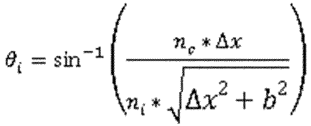 nc Brechungsindex innerhalb des Absorptionshohlraums (110'; 510; 610);ni effektiver Index der geführten Mode im Einkopplungswellenleiter (120'; 520; 620) bzw. im Auskopplungswellenleiter (130'; 530; 630) am Ende dieses Wellenleiters, das sich auf der Seite des Absorptionshohlraums befindet;Δx Abstand zwischen dem Zentrum dieses Wellenleiters (120'; 130'; 520; 530; 620; 630) an dessen Ende, das sich auf der Seite des Absorptionshohlraums befindet, und dem Mittelpunkt (0e) der Ellipse; undb Abstand zwischen dem Mittelpunkt (0e) der Ellipse und dem Grund des Absorptionshohlraums, auf der dem Einkopplungs- und dem Auskopplungswellenleiter entgegengesetzten Seite.
 - Vorrichtung (100; 100'; 500, 600) nach einem der Ansprüche 1 bis 5, dadurch gekennzeichnet, dass der Einkopplungswellenleiter (120; 120'; 520; 620) und der Auskopplungswellenleiter (130; 130'; 530; 630) bezüglich einer Symmetrieebene (112') des Absorptionshohlraums symmetrisch zueinander verlaufen.
- Vorrichtung (100; 100'; 500, 600) nach einem der Ansprüche 1 bis 6, dadurch gekennzeichnet, dass der Abstand zwischen den jeweiligen Zentren des Einkopplungswellenleiters (120; 120'; 520; 620) und des Auskopplungswellenleiters (130; 130'; 530; 630) an ihren jeweiligen Enden auf der Seite des Absorptionshohlraums größer als 5 µm ist.
- Vorrichtung (100; 100'; 500, 600) nach einem der Ansprüche 1 bis 7, dadurch gekennzeichnet, dass die Abmessungen und die Brechungsindizes des Einkopplungswellenleiters (120; 120'; 520; 620) und des Auskopplungswellenleiters (130; 130'; 530; 630) und der Abstand zwischen den jeweiligen Zentren des Einkopplungswellenleiters und des Auskopplungswellenleiters an ihren jeweiligen Enden auf der Seite des Absorptionshohlraums so angepasst sind, dass eine geführte Mode am Austritt des Einkopplungswellenleiters nicht mit einer geführten Mode am Eintritt des Auskopplungswellenleiters interferiert.
- Vorrichtung (500, 600) nach einem der Ansprüche 1 bis 8, dadurch gekennzeichnet, dass der Einkopplungswellenleiter (520; 620) und der Auskopplungswellenleiter (530; 630) durch einen sogenannten Schleifenwellenleiter (570; 670) miteinander verbunden sind, wobei der Einkopplungswellenleiter, der Auskopplungswellenleiter und der Schleifenwellenleiter aus einem Stück miteinander ausgebildet sind.
- Vorrichtung (500, 600) nach Anspruch 9, dadurch gekennzeichnet, dass sie ferner einen so genannten Hauptwellenleiter (580; 680) enthält, der parallel zu einer Tangente zum Schleifenwellenleiter (570; 670) verläuft, um den Analyselichtstrahl vom Hauptwellenleiter (580) in den Schleifenwellenleiter (570) und den Messlichtstrahl vom Schleifenwellenleiter (570) in den Hauptwellenleiter (580) durch evaneszente Kopplung zu übertragen.
- Vorrichtung (600) nach der Anspruch 9 oder 10, dadurch gekennzeichnet, dass der Schleifenwellenleiter (670) sich hinter dem Absorptionshohlraum (610) auf der Seite erstreckt, die einer die jeweiligen Enden des Einkopplungswellenleiters (620) und des Auskopplungswellenleiters aufnehmenden Seite entgegengesetzt ist.
- Chemischer bzw. biologischer Sensor (1000; 5000; 6000), dadurch gekennzeichnet, dass er enthält:- eine optische Vorrichtung (100; 100'; 500; 600) nach einem der Ansprüche 1 bis 11;- eine Lichtquelle (1200; 5200; 6200) zum Emittieren des Analyselichtstrahls (150); und- einen Photodetektor (1300; 5300; 6300) zum Empfangen des Messlichtstrahls (160).
Applications Claiming Priority (2)
| Application Number | Priority Date | Filing Date | Title |
|---|---|---|---|
| FR1657567A FR3054882B1 (fr) | 2016-08-04 | 2016-08-04 | Cavite d'absorption avec guides d'onde d'entree et sortie pour un capteur biologique ou chimique |
| PCT/FR2017/052174 WO2018024991A1 (fr) | 2016-08-04 | 2017-08-03 | Cavité d'absorption avec guides d'onde d'entrée et sortie pour un capteur biologique ou chimique |
Publications (2)
| Publication Number | Publication Date |
|---|---|
| EP3494381A1 EP3494381A1 (de) | 2019-06-12 |
| EP3494381B1 true EP3494381B1 (de) | 2020-05-20 |
Family
ID=57233659
Family Applications (1)
| Application Number | Title | Priority Date | Filing Date |
|---|---|---|---|
| EP17765222.9A Active EP3494381B1 (de) | 2016-08-04 | 2017-08-03 | Absorptionskavität mit eingangs- und ausgangswellenleitern für einen biologischen oder chemischen sensor |
Country Status (4)
| Country | Link |
|---|---|
| US (1) | US11002664B2 (de) |
| EP (1) | EP3494381B1 (de) |
| FR (1) | FR3054882B1 (de) |
| WO (1) | WO2018024991A1 (de) |
Families Citing this family (6)
| Publication number | Priority date | Publication date | Assignee | Title |
|---|---|---|---|---|
| FR3056306B1 (fr) | 2016-09-20 | 2019-11-22 | Commissariat A L'energie Atomique Et Aux Energies Alternatives | Guide optique presentant un virage a pseudo-gradient d'indice |
| FR3069707B1 (fr) | 2017-07-27 | 2019-08-30 | Commissariat A L'energie Atomique Et Aux Energies Alternatives | Dispositif infrarouge |
| US11538758B2 (en) * | 2018-03-19 | 2022-12-27 | Intel Corporation | Waveguide interconnect bridges |
| FR3104259B1 (fr) * | 2019-12-06 | 2024-03-01 | Commissariat Energie Atomique | Dispositif pour la caractérisation photo-acoustique d’une substance gazeuse et procédé de fabrication d’un tel dispositif |
| EP4084091B1 (de) * | 2019-12-27 | 2024-07-10 | Wuhan Optical Valley Information Optoelectronics Innovation Center Co., Ltd | Fotoelektrischer detektor |
| FR3112402B1 (fr) | 2020-07-07 | 2022-10-28 | Commissariat Energie Atomique | Dispositif de démultiplexage en longueur d’onde notamment pour un démultiplexage hors plan. |
Family Cites Families (9)
| Publication number | Priority date | Publication date | Assignee | Title |
|---|---|---|---|---|
| JPS63304137A (ja) * | 1987-06-04 | 1988-12-12 | Sumitomo Electric Ind Ltd | 赤外分光分析器用試料セル |
| DE10216047A1 (de) * | 2002-04-11 | 2003-10-23 | Univ Albert Ludwigs Freiburg | Monolithische Multi-Pass-Zelle |
| FR2869686B1 (fr) * | 2003-12-11 | 2009-06-05 | Flowgene Sa | Detecteur de lumiere a chambre elliptique |
| DE102004010757A1 (de) * | 2004-03-05 | 2005-09-22 | Robert Bosch Gmbh | Gassensor |
| FR2890747B1 (fr) * | 2005-09-15 | 2008-05-09 | Flowgene Sa | Methode et dispositif d'analyse de composes chimiques |
| FR2974423B1 (fr) | 2011-04-19 | 2013-12-27 | Commissariat Energie Atomique | Dispositif d'emission et de guidage d'un rayonnement infrarouge. |
| EP2950731A4 (de) * | 2013-01-31 | 2017-01-04 | Eximo Medical Ltd. | Hybridkathetervorrichtung und verfahren |
| FR3016214B1 (fr) | 2014-01-07 | 2019-09-06 | Commissariat A L'energie Atomique Et Aux Energies Alternatives | Detecteur optique d'un gaz |
| WO2016118431A1 (en) * | 2015-01-19 | 2016-07-28 | Entegris, Inc. | Small volume, long pathlength multi-pass gas cell for ir and uv monitoring |
-
2016
- 2016-08-04 FR FR1657567A patent/FR3054882B1/fr not_active Expired - Fee Related
-
2017
- 2017-08-03 US US16/322,254 patent/US11002664B2/en not_active Expired - Fee Related
- 2017-08-03 EP EP17765222.9A patent/EP3494381B1/de active Active
- 2017-08-03 WO PCT/FR2017/052174 patent/WO2018024991A1/fr not_active Ceased
Non-Patent Citations (1)
| Title |
|---|
| None * |
Also Published As
| Publication number | Publication date |
|---|---|
| US11002664B2 (en) | 2021-05-11 |
| EP3494381A1 (de) | 2019-06-12 |
| WO2018024991A1 (fr) | 2018-02-08 |
| FR3054882B1 (fr) | 2020-10-09 |
| FR3054882A1 (fr) | 2018-02-09 |
| US20190195779A1 (en) | 2019-06-27 |
Similar Documents
| Publication | Publication Date | Title |
|---|---|---|
| EP3494381B1 (de) | Absorptionskavität mit eingangs- und ausgangswellenleitern für einen biologischen oder chemischen sensor | |
| EP3276337B1 (de) | Optische vorrichtung mit mikroresonator mit segmentiertem ring | |
| EP3425344B1 (de) | Bewegungssensor mit mikroresonator mit segmentiertem ring | |
| US7489846B2 (en) | Photonic crystal sensors | |
| FR3019653A1 (fr) | Dispositif de detection a resonateur acoustique differentiel de type helmholtz | |
| US7474396B2 (en) | Raman spectroscopy system and method using a subwavelength resonant grating filter | |
| EP3563140B1 (de) | Vorrichtung zur detektion von gas oder partikeln und verfahren zur herstellung einer solchen vorrichtung | |
| EP2337167A1 (de) | Hybridlaser, mit einem Wellenleiter gekoppelt | |
| EP3650836A1 (de) | Messvorrichtung basiert auf optischer erfassung der bewegung einer opto-mechanischen kavität | |
| EP4016054B1 (de) | Optische komponente für eine atr-bildgebungsvorrichtung | |
| EP3929640B1 (de) | Optisches system mit einer integrierten optischen kopplungsvorrichtung zwischen einer ausgeweiteten laserquelle und einem wellenleiter | |
| FR2953607A1 (fr) | Dispositif de couplage d'une onde electromagnetique entre un guide d'onde et un guide metallique a fente, procede de fabrication dudit dispositif | |
| EP2818921B1 (de) | Vorrichtung zur nicht-linearen Signalumwandlung durch Vermischen von vier Wellen | |
| An et al. | Broadband Long‐Wave Infrared On‐Chip Silicon‐based Surface‐Enhanced Laser Spectroscopy Enabled by Gradient Nanoantenna Array | |
| EP3968066B1 (de) | Wellenleiter, der eine optische multimode-faser umfasst und die geführten moden räumlich konzentrieren kann | |
| WO2021240115A1 (fr) | Dispositif de répartition de lumière basé sur des réseaux de diffraction | |
| EP4016055B1 (de) | Optische komponente für eine interferometrische atr-bildgebungsvorrichtung | |
| EP4345446B1 (de) | Multispektrale reflexionsbildgebungsvorrichtung | |
| EP4187231B1 (de) | Kompakte photoakustische detektionsvorrichtung | |
| FR3110978A1 (fr) | Dispositif de répartition de lumière basé sur un guide d’onde planaire | |
| FR3056769A1 (fr) | Dispositif de couplage d'un premier guide d'ondes avec un deuxieme guide d'ondes | |
| EP4657679A1 (de) | Quantenkaskadenlaser im mittleren infrarotbereich | |
| EP3936912A1 (de) | Wellenlängen-demultiplexervorrichtung, insbesondere für out-of-plane-demultiplexing | |
| FR3154806A1 (fr) | Système opto-mécanique de transduction pour la spectrométrie photo-acoustique |
Legal Events
| Date | Code | Title | Description |
|---|---|---|---|
| STAA | Information on the status of an ep patent application or granted ep patent |
Free format text: STATUS: UNKNOWN |
|
| STAA | Information on the status of an ep patent application or granted ep patent |
Free format text: STATUS: THE INTERNATIONAL PUBLICATION HAS BEEN MADE |
|
| PUAI | Public reference made under article 153(3) epc to a published international application that has entered the european phase |
Free format text: ORIGINAL CODE: 0009012 |
|
| STAA | Information on the status of an ep patent application or granted ep patent |
Free format text: STATUS: REQUEST FOR EXAMINATION WAS MADE |
|
| 17P | Request for examination filed |
Effective date: 20190206 |
|
| AK | Designated contracting states |
Kind code of ref document: A1 Designated state(s): AL AT BE BG CH CY CZ DE DK EE ES FI FR GB GR HR HU IE IS IT LI LT LU LV MC MK MT NL NO PL PT RO RS SE SI SK SM TR |
|
| AX | Request for extension of the european patent |
Extension state: BA ME |
|
| DAV | Request for validation of the european patent (deleted) | ||
| DAX | Request for extension of the european patent (deleted) | ||
| GRAP | Despatch of communication of intention to grant a patent |
Free format text: ORIGINAL CODE: EPIDOSNIGR1 |
|
| STAA | Information on the status of an ep patent application or granted ep patent |
Free format text: STATUS: GRANT OF PATENT IS INTENDED |
|
| INTG | Intention to grant announced |
Effective date: 20191212 |
|
| GRAS | Grant fee paid |
Free format text: ORIGINAL CODE: EPIDOSNIGR3 |
|
| GRAA | (expected) grant |
Free format text: ORIGINAL CODE: 0009210 |
|
| STAA | Information on the status of an ep patent application or granted ep patent |
Free format text: STATUS: THE PATENT HAS BEEN GRANTED |
|
| AK | Designated contracting states |
Kind code of ref document: B1 Designated state(s): AL AT BE BG CH CY CZ DE DK EE ES FI FR GB GR HR HU IE IS IT LI LT LU LV MC MK MT NL NO PL PT RO RS SE SI SK SM TR |
|
| REG | Reference to a national code |
Ref country code: GB Ref legal event code: FG4D Free format text: NOT ENGLISH |
|
| REG | Reference to a national code |
Ref country code: CH Ref legal event code: EP |
|
| REG | Reference to a national code |
Ref country code: DE Ref legal event code: R096 Ref document number: 602017017091 Country of ref document: DE |
|
| REG | Reference to a national code |
Ref country code: AT Ref legal event code: REF Ref document number: 1272908 Country of ref document: AT Kind code of ref document: T Effective date: 20200615 |
|
| REG | Reference to a national code |
Ref country code: LT Ref legal event code: MG4D |
|
| REG | Reference to a national code |
Ref country code: NL Ref legal event code: MP Effective date: 20200520 |
|
| PG25 | Lapsed in a contracting state [announced via postgrant information from national office to epo] |
Ref country code: SE Free format text: LAPSE BECAUSE OF FAILURE TO SUBMIT A TRANSLATION OF THE DESCRIPTION OR TO PAY THE FEE WITHIN THE PRESCRIBED TIME-LIMIT Effective date: 20200520 Ref country code: IS Free format text: LAPSE BECAUSE OF FAILURE TO SUBMIT A TRANSLATION OF THE DESCRIPTION OR TO PAY THE FEE WITHIN THE PRESCRIBED TIME-LIMIT Effective date: 20200920 Ref country code: PT Free format text: LAPSE BECAUSE OF FAILURE TO SUBMIT A TRANSLATION OF THE DESCRIPTION OR TO PAY THE FEE WITHIN THE PRESCRIBED TIME-LIMIT Effective date: 20200921 Ref country code: FI Free format text: LAPSE BECAUSE OF FAILURE TO SUBMIT A TRANSLATION OF THE DESCRIPTION OR TO PAY THE FEE WITHIN THE PRESCRIBED TIME-LIMIT Effective date: 20200520 Ref country code: NO Free format text: LAPSE BECAUSE OF FAILURE TO SUBMIT A TRANSLATION OF THE DESCRIPTION OR TO PAY THE FEE WITHIN THE PRESCRIBED TIME-LIMIT Effective date: 20200820 Ref country code: GR Free format text: LAPSE BECAUSE OF FAILURE TO SUBMIT A TRANSLATION OF THE DESCRIPTION OR TO PAY THE FEE WITHIN THE PRESCRIBED TIME-LIMIT Effective date: 20200821 Ref country code: LT Free format text: LAPSE BECAUSE OF FAILURE TO SUBMIT A TRANSLATION OF THE DESCRIPTION OR TO PAY THE FEE WITHIN THE PRESCRIBED TIME-LIMIT Effective date: 20200520 |
|
| PG25 | Lapsed in a contracting state [announced via postgrant information from national office to epo] |
Ref country code: BG Free format text: LAPSE BECAUSE OF FAILURE TO SUBMIT A TRANSLATION OF THE DESCRIPTION OR TO PAY THE FEE WITHIN THE PRESCRIBED TIME-LIMIT Effective date: 20200820 Ref country code: RS Free format text: LAPSE BECAUSE OF FAILURE TO SUBMIT A TRANSLATION OF THE DESCRIPTION OR TO PAY THE FEE WITHIN THE PRESCRIBED TIME-LIMIT Effective date: 20200520 Ref country code: HR Free format text: LAPSE BECAUSE OF FAILURE TO SUBMIT A TRANSLATION OF THE DESCRIPTION OR TO PAY THE FEE WITHIN THE PRESCRIBED TIME-LIMIT Effective date: 20200520 Ref country code: LV Free format text: LAPSE BECAUSE OF FAILURE TO SUBMIT A TRANSLATION OF THE DESCRIPTION OR TO PAY THE FEE WITHIN THE PRESCRIBED TIME-LIMIT Effective date: 20200520 |
|
| REG | Reference to a national code |
Ref country code: AT Ref legal event code: MK05 Ref document number: 1272908 Country of ref document: AT Kind code of ref document: T Effective date: 20200520 |
|
| PG25 | Lapsed in a contracting state [announced via postgrant information from national office to epo] |
Ref country code: AL Free format text: LAPSE BECAUSE OF FAILURE TO SUBMIT A TRANSLATION OF THE DESCRIPTION OR TO PAY THE FEE WITHIN THE PRESCRIBED TIME-LIMIT Effective date: 20200520 Ref country code: NL Free format text: LAPSE BECAUSE OF FAILURE TO SUBMIT A TRANSLATION OF THE DESCRIPTION OR TO PAY THE FEE WITHIN THE PRESCRIBED TIME-LIMIT Effective date: 20200520 |
|
| PG25 | Lapsed in a contracting state [announced via postgrant information from national office to epo] |
Ref country code: SM Free format text: LAPSE BECAUSE OF FAILURE TO SUBMIT A TRANSLATION OF THE DESCRIPTION OR TO PAY THE FEE WITHIN THE PRESCRIBED TIME-LIMIT Effective date: 20200520 Ref country code: EE Free format text: LAPSE BECAUSE OF FAILURE TO SUBMIT A TRANSLATION OF THE DESCRIPTION OR TO PAY THE FEE WITHIN THE PRESCRIBED TIME-LIMIT Effective date: 20200520 Ref country code: IT Free format text: LAPSE BECAUSE OF FAILURE TO SUBMIT A TRANSLATION OF THE DESCRIPTION OR TO PAY THE FEE WITHIN THE PRESCRIBED TIME-LIMIT Effective date: 20200520 Ref country code: AT Free format text: LAPSE BECAUSE OF FAILURE TO SUBMIT A TRANSLATION OF THE DESCRIPTION OR TO PAY THE FEE WITHIN THE PRESCRIBED TIME-LIMIT Effective date: 20200520 Ref country code: DK Free format text: LAPSE BECAUSE OF FAILURE TO SUBMIT A TRANSLATION OF THE DESCRIPTION OR TO PAY THE FEE WITHIN THE PRESCRIBED TIME-LIMIT Effective date: 20200520 Ref country code: RO Free format text: LAPSE BECAUSE OF FAILURE TO SUBMIT A TRANSLATION OF THE DESCRIPTION OR TO PAY THE FEE WITHIN THE PRESCRIBED TIME-LIMIT Effective date: 20200520 Ref country code: CZ Free format text: LAPSE BECAUSE OF FAILURE TO SUBMIT A TRANSLATION OF THE DESCRIPTION OR TO PAY THE FEE WITHIN THE PRESCRIBED TIME-LIMIT Effective date: 20200520 Ref country code: ES Free format text: LAPSE BECAUSE OF FAILURE TO SUBMIT A TRANSLATION OF THE DESCRIPTION OR TO PAY THE FEE WITHIN THE PRESCRIBED TIME-LIMIT Effective date: 20200520 |
|
| REG | Reference to a national code |
Ref country code: DE Ref legal event code: R097 Ref document number: 602017017091 Country of ref document: DE |
|
| PG25 | Lapsed in a contracting state [announced via postgrant information from national office to epo] |
Ref country code: PL Free format text: LAPSE BECAUSE OF FAILURE TO SUBMIT A TRANSLATION OF THE DESCRIPTION OR TO PAY THE FEE WITHIN THE PRESCRIBED TIME-LIMIT Effective date: 20200520 Ref country code: SK Free format text: LAPSE BECAUSE OF FAILURE TO SUBMIT A TRANSLATION OF THE DESCRIPTION OR TO PAY THE FEE WITHIN THE PRESCRIBED TIME-LIMIT Effective date: 20200520 |
|
| PLBE | No opposition filed within time limit |
Free format text: ORIGINAL CODE: 0009261 |
|
| STAA | Information on the status of an ep patent application or granted ep patent |
Free format text: STATUS: NO OPPOSITION FILED WITHIN TIME LIMIT |
|
| PG25 | Lapsed in a contracting state [announced via postgrant information from national office to epo] |
Ref country code: MC Free format text: LAPSE BECAUSE OF FAILURE TO SUBMIT A TRANSLATION OF THE DESCRIPTION OR TO PAY THE FEE WITHIN THE PRESCRIBED TIME-LIMIT Effective date: 20200520 |
|
| REG | Reference to a national code |
Ref country code: CH Ref legal event code: PL |
|
| 26N | No opposition filed |
Effective date: 20210223 |
|
| PG25 | Lapsed in a contracting state [announced via postgrant information from national office to epo] |
Ref country code: CH Free format text: LAPSE BECAUSE OF NON-PAYMENT OF DUE FEES Effective date: 20200831 Ref country code: LI Free format text: LAPSE BECAUSE OF NON-PAYMENT OF DUE FEES Effective date: 20200831 Ref country code: LU Free format text: LAPSE BECAUSE OF NON-PAYMENT OF DUE FEES Effective date: 20200803 |
|
| REG | Reference to a national code |
Ref country code: BE Ref legal event code: MM Effective date: 20200831 |
|
| PG25 | Lapsed in a contracting state [announced via postgrant information from national office to epo] |
Ref country code: SI Free format text: LAPSE BECAUSE OF FAILURE TO SUBMIT A TRANSLATION OF THE DESCRIPTION OR TO PAY THE FEE WITHIN THE PRESCRIBED TIME-LIMIT Effective date: 20200520 |
|
| PG25 | Lapsed in a contracting state [announced via postgrant information from national office to epo] |
Ref country code: BE Free format text: LAPSE BECAUSE OF NON-PAYMENT OF DUE FEES Effective date: 20200831 Ref country code: IE Free format text: LAPSE BECAUSE OF NON-PAYMENT OF DUE FEES Effective date: 20200803 |
|
| PG25 | Lapsed in a contracting state [announced via postgrant information from national office to epo] |
Ref country code: TR Free format text: LAPSE BECAUSE OF FAILURE TO SUBMIT A TRANSLATION OF THE DESCRIPTION OR TO PAY THE FEE WITHIN THE PRESCRIBED TIME-LIMIT Effective date: 20200520 Ref country code: MT Free format text: LAPSE BECAUSE OF FAILURE TO SUBMIT A TRANSLATION OF THE DESCRIPTION OR TO PAY THE FEE WITHIN THE PRESCRIBED TIME-LIMIT Effective date: 20200520 Ref country code: CY Free format text: LAPSE BECAUSE OF FAILURE TO SUBMIT A TRANSLATION OF THE DESCRIPTION OR TO PAY THE FEE WITHIN THE PRESCRIBED TIME-LIMIT Effective date: 20200520 |
|
| PG25 | Lapsed in a contracting state [announced via postgrant information from national office to epo] |
Ref country code: MK Free format text: LAPSE BECAUSE OF FAILURE TO SUBMIT A TRANSLATION OF THE DESCRIPTION OR TO PAY THE FEE WITHIN THE PRESCRIBED TIME-LIMIT Effective date: 20200520 |
|
| PGFP | Annual fee paid to national office [announced via postgrant information from national office to epo] |
Ref country code: GB Payment date: 20220824 Year of fee payment: 6 Ref country code: DE Payment date: 20220822 Year of fee payment: 6 |
|
| PGFP | Annual fee paid to national office [announced via postgrant information from national office to epo] |
Ref country code: FR Payment date: 20220822 Year of fee payment: 6 |
|
| REG | Reference to a national code |
Ref country code: DE Ref legal event code: R119 Ref document number: 602017017091 Country of ref document: DE |
|
| GBPC | Gb: european patent ceased through non-payment of renewal fee |
Effective date: 20230803 |
|
| PG25 | Lapsed in a contracting state [announced via postgrant information from national office to epo] |
Ref country code: GB Free format text: LAPSE BECAUSE OF NON-PAYMENT OF DUE FEES Effective date: 20230803 |
|
| PG25 | Lapsed in a contracting state [announced via postgrant information from national office to epo] |
Ref country code: GB Free format text: LAPSE BECAUSE OF NON-PAYMENT OF DUE FEES Effective date: 20230803 Ref country code: FR Free format text: LAPSE BECAUSE OF NON-PAYMENT OF DUE FEES Effective date: 20230831 Ref country code: DE Free format text: LAPSE BECAUSE OF NON-PAYMENT OF DUE FEES Effective date: 20240301 |