EP3495192B1 - Steuergerät zur steuerung einer ausgangsleistung eines elektrofahrzeugs, elektrofahrzeug mit solch einem steuergerät und zugehöriges verfahren - Google Patents
Steuergerät zur steuerung einer ausgangsleistung eines elektrofahrzeugs, elektrofahrzeug mit solch einem steuergerät und zugehöriges verfahren Download PDFInfo
- Publication number
- EP3495192B1 EP3495192B1 EP17205824.0A EP17205824A EP3495192B1 EP 3495192 B1 EP3495192 B1 EP 3495192B1 EP 17205824 A EP17205824 A EP 17205824A EP 3495192 B1 EP3495192 B1 EP 3495192B1
- Authority
- EP
- European Patent Office
- Prior art keywords
- controller
- power
- electric vehicle
- user
- mode
- Prior art date
- Legal status (The legal status is an assumption and is not a legal conclusion. Google has not performed a legal analysis and makes no representation as to the accuracy of the status listed.)
- Active
Links
Images

Classifications
-
- B—PERFORMING OPERATIONS; TRANSPORTING
- B60—VEHICLES IN GENERAL
- B60L—PROPULSION OF ELECTRICALLY-PROPELLED VEHICLES; SUPPLYING ELECTRIC POWER FOR AUXILIARY EQUIPMENT OF ELECTRICALLY-PROPELLED VEHICLES; ELECTRODYNAMIC BRAKE SYSTEMS FOR VEHICLES IN GENERAL; MAGNETIC SUSPENSION OR LEVITATION FOR VEHICLES; MONITORING OPERATING VARIABLES OF ELECTRICALLY-PROPELLED VEHICLES; ELECTRIC SAFETY DEVICES FOR ELECTRICALLY-PROPELLED VEHICLES
- B60L15/00—Methods, circuits, or devices for controlling the traction-motor speed of electrically-propelled vehicles
- B60L15/20—Methods, circuits, or devices for controlling the traction-motor speed of electrically-propelled vehicles for control of the vehicle or its driving motor to achieve a desired performance, e.g. speed, torque, programmed variation of speed
- B60L15/2045—Methods, circuits, or devices for controlling the traction-motor speed of electrically-propelled vehicles for control of the vehicle or its driving motor to achieve a desired performance, e.g. speed, torque, programmed variation of speed for optimising the use of energy
-
- B—PERFORMING OPERATIONS; TRANSPORTING
- B60—VEHICLES IN GENERAL
- B60L—PROPULSION OF ELECTRICALLY-PROPELLED VEHICLES; SUPPLYING ELECTRIC POWER FOR AUXILIARY EQUIPMENT OF ELECTRICALLY-PROPELLED VEHICLES; ELECTRODYNAMIC BRAKE SYSTEMS FOR VEHICLES IN GENERAL; MAGNETIC SUSPENSION OR LEVITATION FOR VEHICLES; MONITORING OPERATING VARIABLES OF ELECTRICALLY-PROPELLED VEHICLES; ELECTRIC SAFETY DEVICES FOR ELECTRICALLY-PROPELLED VEHICLES
- B60L15/00—Methods, circuits, or devices for controlling the traction-motor speed of electrically-propelled vehicles
- B60L15/20—Methods, circuits, or devices for controlling the traction-motor speed of electrically-propelled vehicles for control of the vehicle or its driving motor to achieve a desired performance, e.g. speed, torque, programmed variation of speed
- B60L15/2054—Methods, circuits, or devices for controlling the traction-motor speed of electrically-propelled vehicles for control of the vehicle or its driving motor to achieve a desired performance, e.g. speed, torque, programmed variation of speed by controlling transmissions or clutches
-
- B—PERFORMING OPERATIONS; TRANSPORTING
- B60—VEHICLES IN GENERAL
- B60L—PROPULSION OF ELECTRICALLY-PROPELLED VEHICLES; SUPPLYING ELECTRIC POWER FOR AUXILIARY EQUIPMENT OF ELECTRICALLY-PROPELLED VEHICLES; ELECTRODYNAMIC BRAKE SYSTEMS FOR VEHICLES IN GENERAL; MAGNETIC SUSPENSION OR LEVITATION FOR VEHICLES; MONITORING OPERATING VARIABLES OF ELECTRICALLY-PROPELLED VEHICLES; ELECTRIC SAFETY DEVICES FOR ELECTRICALLY-PROPELLED VEHICLES
- B60L15/00—Methods, circuits, or devices for controlling the traction-motor speed of electrically-propelled vehicles
- B60L15/20—Methods, circuits, or devices for controlling the traction-motor speed of electrically-propelled vehicles for control of the vehicle or its driving motor to achieve a desired performance, e.g. speed, torque, programmed variation of speed
- B60L15/209—Methods, circuits, or devices for controlling the traction-motor speed of electrically-propelled vehicles for control of the vehicle or its driving motor to achieve a desired performance, e.g. speed, torque, programmed variation of speed for overtaking
-
- B—PERFORMING OPERATIONS; TRANSPORTING
- B60—VEHICLES IN GENERAL
- B60L—PROPULSION OF ELECTRICALLY-PROPELLED VEHICLES; SUPPLYING ELECTRIC POWER FOR AUXILIARY EQUIPMENT OF ELECTRICALLY-PROPELLED VEHICLES; ELECTRODYNAMIC BRAKE SYSTEMS FOR VEHICLES IN GENERAL; MAGNETIC SUSPENSION OR LEVITATION FOR VEHICLES; MONITORING OPERATING VARIABLES OF ELECTRICALLY-PROPELLED VEHICLES; ELECTRIC SAFETY DEVICES FOR ELECTRICALLY-PROPELLED VEHICLES
- B60L58/00—Methods or circuit arrangements for monitoring or controlling batteries or fuel cells, specially adapted for electric vehicles
- B60L58/10—Methods or circuit arrangements for monitoring or controlling batteries or fuel cells, specially adapted for electric vehicles for monitoring or controlling batteries
-
- B—PERFORMING OPERATIONS; TRANSPORTING
- B60—VEHICLES IN GENERAL
- B60L—PROPULSION OF ELECTRICALLY-PROPELLED VEHICLES; SUPPLYING ELECTRIC POWER FOR AUXILIARY EQUIPMENT OF ELECTRICALLY-PROPELLED VEHICLES; ELECTRODYNAMIC BRAKE SYSTEMS FOR VEHICLES IN GENERAL; MAGNETIC SUSPENSION OR LEVITATION FOR VEHICLES; MONITORING OPERATING VARIABLES OF ELECTRICALLY-PROPELLED VEHICLES; ELECTRIC SAFETY DEVICES FOR ELECTRICALLY-PROPELLED VEHICLES
- B60L2200/00—Type of vehicles
- B60L2200/12—Bikes
-
- B—PERFORMING OPERATIONS; TRANSPORTING
- B60—VEHICLES IN GENERAL
- B60L—PROPULSION OF ELECTRICALLY-PROPELLED VEHICLES; SUPPLYING ELECTRIC POWER FOR AUXILIARY EQUIPMENT OF ELECTRICALLY-PROPELLED VEHICLES; ELECTRODYNAMIC BRAKE SYSTEMS FOR VEHICLES IN GENERAL; MAGNETIC SUSPENSION OR LEVITATION FOR VEHICLES; MONITORING OPERATING VARIABLES OF ELECTRICALLY-PROPELLED VEHICLES; ELECTRIC SAFETY DEVICES FOR ELECTRICALLY-PROPELLED VEHICLES
- B60L2240/00—Control parameters of input or output; Target parameters
- B60L2240/80—Time limits
-
- B—PERFORMING OPERATIONS; TRANSPORTING
- B60—VEHICLES IN GENERAL
- B60L—PROPULSION OF ELECTRICALLY-PROPELLED VEHICLES; SUPPLYING ELECTRIC POWER FOR AUXILIARY EQUIPMENT OF ELECTRICALLY-PROPELLED VEHICLES; ELECTRODYNAMIC BRAKE SYSTEMS FOR VEHICLES IN GENERAL; MAGNETIC SUSPENSION OR LEVITATION FOR VEHICLES; MONITORING OPERATING VARIABLES OF ELECTRICALLY-PROPELLED VEHICLES; ELECTRIC SAFETY DEVICES FOR ELECTRICALLY-PROPELLED VEHICLES
- B60L2260/00—Operating Modes
- B60L2260/10—Temporary overload
- B60L2260/16—Temporary overload of electrical drive trains
- B60L2260/167—Temporary overload of electrical drive trains of motors or generators
-
- B—PERFORMING OPERATIONS; TRANSPORTING
- B60—VEHICLES IN GENERAL
- B60L—PROPULSION OF ELECTRICALLY-PROPELLED VEHICLES; SUPPLYING ELECTRIC POWER FOR AUXILIARY EQUIPMENT OF ELECTRICALLY-PROPELLED VEHICLES; ELECTRODYNAMIC BRAKE SYSTEMS FOR VEHICLES IN GENERAL; MAGNETIC SUSPENSION OR LEVITATION FOR VEHICLES; MONITORING OPERATING VARIABLES OF ELECTRICALLY-PROPELLED VEHICLES; ELECTRIC SAFETY DEVICES FOR ELECTRICALLY-PROPELLED VEHICLES
- B60L2260/00—Operating Modes
- B60L2260/20—Drive modes; Transition between modes
- B60L2260/26—Transition between different drive modes
-
- Y—GENERAL TAGGING OF NEW TECHNOLOGICAL DEVELOPMENTS; GENERAL TAGGING OF CROSS-SECTIONAL TECHNOLOGIES SPANNING OVER SEVERAL SECTIONS OF THE IPC; TECHNICAL SUBJECTS COVERED BY FORMER USPC CROSS-REFERENCE ART COLLECTIONS [XRACs] AND DIGESTS
- Y02—TECHNOLOGIES OR APPLICATIONS FOR MITIGATION OR ADAPTATION AGAINST CLIMATE CHANGE
- Y02T—CLIMATE CHANGE MITIGATION TECHNOLOGIES RELATED TO TRANSPORTATION
- Y02T10/00—Road transport of goods or passengers
- Y02T10/60—Other road transportation technologies with climate change mitigation effect
- Y02T10/64—Electric machine technologies in electromobility
-
- Y—GENERAL TAGGING OF NEW TECHNOLOGICAL DEVELOPMENTS; GENERAL TAGGING OF CROSS-SECTIONAL TECHNOLOGIES SPANNING OVER SEVERAL SECTIONS OF THE IPC; TECHNICAL SUBJECTS COVERED BY FORMER USPC CROSS-REFERENCE ART COLLECTIONS [XRACs] AND DIGESTS
- Y02—TECHNOLOGIES OR APPLICATIONS FOR MITIGATION OR ADAPTATION AGAINST CLIMATE CHANGE
- Y02T—CLIMATE CHANGE MITIGATION TECHNOLOGIES RELATED TO TRANSPORTATION
- Y02T10/00—Road transport of goods or passengers
- Y02T10/60—Other road transportation technologies with climate change mitigation effect
- Y02T10/70—Energy storage systems for electromobility, e.g. batteries
-
- Y—GENERAL TAGGING OF NEW TECHNOLOGICAL DEVELOPMENTS; GENERAL TAGGING OF CROSS-SECTIONAL TECHNOLOGIES SPANNING OVER SEVERAL SECTIONS OF THE IPC; TECHNICAL SUBJECTS COVERED BY FORMER USPC CROSS-REFERENCE ART COLLECTIONS [XRACs] AND DIGESTS
- Y02—TECHNOLOGIES OR APPLICATIONS FOR MITIGATION OR ADAPTATION AGAINST CLIMATE CHANGE
- Y02T—CLIMATE CHANGE MITIGATION TECHNOLOGIES RELATED TO TRANSPORTATION
- Y02T10/00—Road transport of goods or passengers
- Y02T10/60—Other road transportation technologies with climate change mitigation effect
- Y02T10/72—Electric energy management in electromobility
Definitions
- the invention regards a controller for controlling an output power of an electric vehicle, electric vehicle, in particular an electric off-road motorcycle, comprising such controller and corresponding method.
- One approach is to find a compromise between an upper limit of output power torque produced by the motor when the user fully opens the throttle and other aspects of driving like controllability or conditions under which the vehicle is driven.
- Such conditions may for example be the remaining driving distance depending on the state of charge (SOC) of the battery, a current battery temperature and/or wear level of the battery or other constraints like heat management or the like.
- the conditions and constraints under which the vehicle is operated may vary.
- the controller controlling the output of power or torque in response to a demand indicated by a throttle signal calculates an energy amount supplied to the motor of the vehicle according to a drive mode in which the controller is operated.
- the drive mode defines an algorithm that defines a power output depending from input parameters.
- a controller may use one of a plurality of such drive modes that are either set according to a user input or set automatically, which is advantageous when critical system parameters are measured, for example an excessive high temperature of one of the system components or a low SOC.
- a controller for controlling an output power of an electric vehicle in which all features of the preamble of claim 1 are disclosed, is described in Tesla Motors: “2017 Tesla Model S Owner's Manual", 3 December 2017, pages 1 - 186, Fermont, California, USA .
- the controller according to the invention is used to control an output power of a motor that propels the vehicle by controlling the amount of energy that is supplied to the motor.
- the controller generally determines this energy amount or the power to be output by the motor based on a throttle signal which is received from a throttle operated by a user. With such throttle, in case of a motorcycle usually a rotatable handle grip, the driver or rider indicates his output power wish.
- the controller is operated in a driving mode that essentially consists of an algorithm that includes the rules for determining the output power or energy to be provided taking into consideration at least the throttle signal, but preferably also other system parameters, like SOC of the battery, temperature and so on as listed above already.
- the duration of the time interval is directly controlled by the duration of the user input that generates the further signal.
- the additional power is then available exactly as long as the user indicates.
- the maximum length of the time interval is predetermined. The switching back to the original drive mode will then occur when a maximum duration from start of the operation is reached. In case that the user forgets about to release of the signal it is then ensured that the usual drive mode is nevertheless used again.
- the maximum duration is advantageously set so that most of the exceptional driving situations are well covered.
- the drive mode is one of a plurality of available drive modes which can be set by a user or that are set automatically based on measurable system parameters of the electric vehicle and the maximum energy that may be delivered to the motor is set in accordance with the currently used drive mode.
- the maximum power available may thus depend if the initial drive mode already is a drive mode with limited power output, for example when a low SOC is recognized, or a regular drive mode which limits the power only due to high temperatures or the like.
- the power switch which is operated by the user is a pushbutton, advantageously mounted on a handle bar of the motorcycle. Further advantageously, the pushbutton is arranged in a recess so that unintended operation is avoided. If the switch short circuits a pin of the controller only one wire is necessary and slightly adapted engine stop switches as commonly used for dirt bikes can be used.
- the switch can be realized in the form of a clutch lever. Then, the rider who is used to use a clutch in some of the situations may in a similar way operate the clutch lever like switch and again unintentional operation of such power switch is avoided. Further, using a clutch lever design for the switch allows that the thumb still holds the handlebar which improves control over the motorcycle.
- the invention is particularly useful for controlling the available output power of an off-road motorcycle.
- a motorcycle will be used for explanation and its operator or user is designated as rider.
- Fig. 1 is a schematic that shows the main components of an electric drive system 1 of an electric motorcycle.
- the central unit is a controller 2 which receives information on the system from various sensors and which is connected to a rechargeable battery 3.
- the rechargeable battery 3 stores electric energy and is charged by means of a charger, not shown in Fig. 1 .
- the controller 2 receives information on the status of the rechargeable battery 3 via a battery management system 4. This information includes, but is not limited to, temperature of the rechargeable battery 3 and state of charge (SOC). Using this information, the controller 2 can determine how much electric energy (per time unit) can reasonably be taken out of the rechargeable battery 3 to provide a motor 5 (electrical engine) with electric power and without badly affecting the temperature of the system or the like. In a known manner the controller 2 determines an upper limit for the current taken out of the rechargeable battery 3. Up to this upper limit the current taken out of the battery 3 and being supplied to the motor 5 can be set freely. The controller 2 sets the actual amount based on a demand that is indicated by the rider of the motorcycle.
- SOC state of charge
- the rider operates in a well-known manner which does not distinguish from a motorcycle having an internal combustion engine a throttle grip.
- the throttle grip includes a sensor 15 that determines an angle about which the grip has been rotated and generates a signal being fed to the controller 2 as a throttle input signal.
- the throttle input signal is used in the controller 2 to determine a torque request from the rider.
- the controller comprises a processor 2.1 which processes the received information to determine an output torque of the motor which is equivalent to a current for the motor 5. This determination is performed by executing a program stored in a non-volatile memory 2.2 of the controller 2.
- a program stored in a non-volatile memory 2.2 of the controller 2.
- memory 2.2 holds only one program which is loaded into the processor 2.1 upon power up of the system and executes this program using a fixed parameter set.
- a mode switch 6 is operated by the rider of the motorcycle in order to select one out of a plurality of drive modes.
- Different drive modes may be for example optimized for long distance travelling, track, road, rain and so on. It is preferred that these different drive modes all use the same program but with different parameter sets which are stored in the memory 2.2 and which are set in the program after the respective mode has been selected by the rider.
- the parameter sets are optimized for different compromises between remaining distance and power output.
- the process of selecting one of a plurality of drive modes is known in the art as well as the different modes themselves and the components as described above fulfil their well-known tasks for operating the electric motorcycle. According to the invention there is now an additional possibility for the rider to influence the way the controller 2 determines the power output in response to the throttle input signal. While the controller 2 controls the motor 5 using the selected drive mode in which typically the upper limit current is less than a maximum current that could be delivered by the rechargeable battery 3, the user can operate a power switch 7 independently from the operation of the throttle grip.
- the signal being output by the power switch 7 is preferably an "on/off"-type signal. The duration of the signal is controlled by the rider.
- the controller 2 is connected to the power switch 7 and thus receives an "on"-signal when the rider operates the power switch 7.
- the controller 2 When the controller 2 receives such power "on"-signal it ignores all the limiting factors that are taken in account when the operation is performed according to the selected drive mode. The controller 2 rather determines the maximum power available using the maximum possible current from the rechargeable battery 3. Thus, independently from the effect such power output from the motor 5 on the remaining distance, temperature of the system 1 and the like, the maximum possible output power is unlocked.
- the controller 2 is configured to adjust the current supplied to the engine in response to a fully opened throttle to this maximum current and as a result the maximum possible power or torque is output by the motor 5.
- the controller 2 will set the current accordingly.
- the rider can overrule the drive mode by such maximum power mode.
- the controller 2 switches back to its initially executed drive mode.
- the start of the operation and releasing the power switch 7 define a duration during which the controller is in the maximum power mode, provided that this duration is not longer than a predetermined maximum duration.
- the controller 2 remembers the initial drive mode that was left and turns back to it.
- the maximum duration for a time interval in which the controller 2 is operated in the maximum power mode is limited.
- the time interval is defined by the operation duration of the power switch 7. When the time interval exceeds this limit the controller 2 will also return into the initial drive mode.
- the power switch 7 connects one pin of the controller 2 with ground when the power switch 7 is operated. This pulls down a potential in the controller 2 which can be detected by the controller 2.
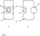
- a power switch 7 that can easily be mounted on a handlebar of a motorcycle is shown in Fig 2 a, b .
- the power switch 7 comprises a housing 8 through which a pushbutton 9 protrudes.
- the pushbutton 9 is sealed with a sealing 10 against dirt and water.
- the pushbutton 9 is arranged in a recessed portion 11 of the housing 8 so that accidental operation of the pushbutton 9 is avoided.
- the recess 11 and its function can easily be understood looking at fig. 2b . It is evident that the pushbutton 9 protrudes from the housing 8 of the power switch 7 only to such an extent that its user oriented surface of the housing 8 is approximately flat with the housing 8 in the not recessed area.
- Fig. 2b further shows that the power switch 7 being designed as a pushbutton 9 is mounted on a handlebar 12 which is indicated in cross section.
- the pushbutton 9 is biased by a spring to return into its idle position. Similar switches are known for motorcycles to interrupt the ignition but with a flat housing and projecting pushbutton so that the pushbutton may be reached easily under all circumstances and accidental operation might occur.
- the power switch 7 could be designed like a clutch lever. Then, instead of the regular clutch lever which in not necessary for electric motorcycles, such power switch 7 could be mounted. Since many of the regular clutch levers have a sensor for sensing whether the clutch is operated or not, such clutch lever could directly be used as a power switch 7 when the clutch sensor is connected to the controller 2.
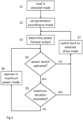
- step S1 the selected drive mode is read in from a mode switch 6 which can be any kind of user interface.
- the parameters for operating the vehicle in this selected drive mode are retrieved from memory 2.2 in step S2.
- the processor 2.1 then operates the vehicle or rather the drive system 1 of the vehicle in the selected drive mode in which the power output/torque, or equivalently the electric energy that is necessary to be supplied to the motor 5 to realize the desired output power, is determined (step S3)
- step S4 While the controller 2 operates the vehicle in the selected drive mode, operation of the power switch 7 is monitored in step S4. If it is recognized that the power switch 7 is operated, it is further determined whether the time interval from the beginning of the operation already exceeds a maximum duration (step S5). The controller 2 is switched to the maximum power drive mode if not and if currently the controller 2 is operating in the selected drive mode in step S6. The output power is then determined according to the maximum power mode. The process then returns to step S4 to observe if the power switch 7 is still operated and if the maximum duration is not exceeded. Of course, if the controller 2 is already in the maximum power mode, step 6 can be ignored then and the maximum power mode is maintained.
- step S4 If on the other hand in step S4 it is determined that the power switch 7 is not operated any more, or, in case the drive mode is still on, has not been operated at all, the controller 2 is switched back into the selected drive mode or maintained in the selected drive mode in S7. Then, the output is determined again according to the selected drive mode.
- the invention is not limited to the example of an electric motorcycle but can be applied to other electric vehicles as well.
Landscapes
- Engineering & Computer Science (AREA)
- Power Engineering (AREA)
- Transportation (AREA)
- Mechanical Engineering (AREA)
- Life Sciences & Earth Sciences (AREA)
- Sustainable Development (AREA)
- Sustainable Energy (AREA)
- Electric Propulsion And Braking For Vehicles (AREA)
Claims (10)
- Steuergerät zur Steuerung einer Ausgabeleistung eines Elektrofahrzeugs, das von einer Batterie (3) eines elektrischen Antriebssystems (1) des Elektrofahrzeugs angetrieben wird, wobei das Steuergerät (2) ausgebildet ist, umüber ein Batteriemanagementsystem (4) des elektrischen Antriebssystems (1) Informationen über einen Status der Batterie (3) zu empfangen,für einen Fahrmodus auf der Grundlage der empfangenen Informationen einen oberen Grenzwert für die von dem Motor erzeugte Ausgabeleistung zu bestimmen, wenn der Benutzer die Drosselklappe vollständig öffnet, so dass die Temperatur des elektrischen Antriebssystems (1) nicht beeinträchtigt wird,im Antriebsmodus die elektrische Leistung für einen ein Drehmoment zum Antreiben des Fahrzeugs auf der Grundlage eines Drosselklappeneingangssignals und des oberen Grenzwerts erzeugenden Motor (5) zu steuern,zusätzlich zu dem Drosselklappeneingangssignal ein weiteres vom Benutzer steuerbares Signal zu empfangen,dadurch gekennzeichnet, dassdas Steuergerät (2) ferner so konfiguriert ist, dass es, in Reaktion auf ein solches vom Benutzer steuerbares Signal, für ein Zeitintervall in einen Modus maximaler Leistung umschaltet, wobei das Zeitintervall einer durch den Beginn einer Betätigung eines Leistungsschalters (7) und das Loslassen des Leistungsschalters (7) definierten Dauer des von dem Steuergerät (2) empfangenen vom Benutzer steuerbaren Signals entspricht, wobei für das Zeitintervall ein vorbestimmtes Maximum eingestellt ist,im Modus der maximalen Leistung der obere Grenzwert ignoriert wird, so dass die maximale Leistung, die an den Motor (5) abgegeben werden kann, im Vergleich zum Antriebsmodus erhöht wird, unabhängig von einer Auswirkung der maximalen Leistung auf die Temperatur des elektrischen Antriebssystems (1).
- Steuergerät für ein Elektrofahrzeug nach Anspruch 1,
dadurch gekennzeichnet, dass
der Fahrmodus einer von mehreren verfügbaren Fahrmodi ist, die von einem Benutzer eingestellt werden können oder die auf der Grundlage von messbaren Systemparametern des Elektrofahrzeugs automatisch eingestellt werden, wobei die maximale Leistung, die an den Motor (5) abgegeben werden kann, entsprechend dem aktuell verwendeten Fahrmodus eingestellt wird. - Elektrofahrzeug mit einer Stromspeichereinheit (3), einem Motor (5) zur Erzeugung eines Antriebsmoments, einer Drosselklappe, die in Abhängigkeit von der Betätigung durch einen Benutzer ein Drosselklappensignal erzeugt, einem Steuergerät (2) nach Anspruch 1 oder 2 und dem in Abhängigkeit von einer Betätigung des Benutzers ein Signal erzeugenden Leistungsschalter (7), wobei die Dauer des Signals der Betätigung des Leistungsschalters (7) durch den Benutzer entspricht.
- Elektrofahrzeug nach Anspruch 3,
dadurch gekennzeichnet, dass
das Elektrofahrzeug ein geländegängiges Motorrad ist. - Elektrofahrzeug nach Anspruch 3 oder 4,
dadurch gekennzeichnet, dass
der Leistungsschalter (7) einen Druckknopf (9) umfasst. - Elektrofahrzeug nach Anspruch 5,
dadurch gekennzeichnet, dass
der Druckknopf (9) in einer Ausnehmung des Leistungsschaltergehäuses (8) angeordnet ist. - Elektrofahrzeug nach einem der Ansprüche 3 bis 6,
dadurch gekennzeichnet, dass
der Leistungsschalter (7) als Kupplungshebel ausgebildet ist. - Elektrofahrzeug nach einem der Ansprüche 3 bis 7,
dadurch gekennzeichnet, dass
in Reaktion auf eine Betätigung des Leistungsschalters (7) ein Eingangsanschluß des Steuergerätes (2) kurzgeschlossen wird. - Verfahren zur Steuerung einer Ausgabeleistung eines Elektrofahrzeugs, das von einer Batterie (3) eines elektrischen Antriebssystems (1) des Elektrofahrzeugs angetrieben wird, aufweisend die folgenden Schritte:- Empfangen, über ein Batteriemanagementsystem (4) des elektrischen Antriebssystems (1), von Informationen über einen Status der Batterie,- Bestimmen, für einen Fahrmodus, auf Grundlage der empfangenen Informationen, eines oberen Grenzwertes der Ausgabeleistung, die von dem Motor erzeugt wird, wenn der Benutzer die Drosselklappe vollständig öffnet, so dass die Temperatur des elektrischen Antriebssystems (1) nicht beeinträchtigt wird,- Betreiben des Elektrofahrzeugs im Fahrmodus (S3) durch einen Prozessor (2.1), der auf Grundlage eines Drosseleingangssignals und des oberen Grenzwertes die elektrische Leistung für einen ein Drehmoment zum Antreiben des Fahrzeugs erzeugenden Motor (5) steuert,- Empfangen (S4), zusätzlich zu dem Drosselklappeneingangssignal, eines weiteren vom Benutzer steuerbaren Signals und
gekennzeichnet durch- Umschalten (S6), in Reaktion auf ein solches vom Benutzer steuerbares Signal, in einen Modus maximaler Leistung für ein Zeitintervall, wobei das Zeitintervall, in dem das Steuergerät (2) in dem Modus maximaler Leistung arbeitet, einer durch den Beginn einer Betätigung eines Leistungsschalters (7) und das Loslassen des Leistungsschalters (7) definierten Dauer des von dem Steuergerät (2) empfangenen vom Benutzer steuerbaren Signals entspricht, und das Steuergerät (2) zurück in den Antriebsmodus (S7) schaltet, wenn die Dauer des weiteren Signals ein vorgegebenes Maximum überschreitet,im Modus maximaler Leistung der obere Grenzwert ignoriert wird, so dass die maximale Leistung, die an den Motor (5) abgegeben werden kann, im Vergleich zum Antriebsmodus erhöht wird, unabhängig von einer Beeinflussung der maximalen Leistung auf die Temperatur des elektrischen Antriebssystems (1). - Verfahren nach Anspruch 9,
dadurch gekennzeichnet, dass
der Fahrmodus einer von mehreren verfügbaren Fahrmodi ist, die von einem Benutzer (S 1) eingestellt werden können oder die auf Grundlage messbarer Systemparameter des Elektrofahrzeugs automatisch eingestellt werden, wobei die maximale Leistung, die an den Motor abgegeben werden kann, entsprechend dem aktuell verwendeten Fahrmodus eingestellt wird.
Priority Applications (3)
| Application Number | Priority Date | Filing Date | Title |
|---|---|---|---|
| EP17205824.0A EP3495192B1 (de) | 2017-12-07 | 2017-12-07 | Steuergerät zur steuerung einer ausgangsleistung eines elektrofahrzeugs, elektrofahrzeug mit solch einem steuergerät und zugehöriges verfahren |
| JP2018211589A JP2019106873A (ja) | 2017-12-07 | 2018-11-09 | 電気車両の出力パワーを制御する制御装置、その制御装置を備えた電気車両、および対応する方法 |
| US16/209,096 US11130410B2 (en) | 2017-12-07 | 2018-12-04 | Controller for controlling an output power of an electric vehicle, electric vehicle comprising such controller and corresponding method |
Applications Claiming Priority (1)
| Application Number | Priority Date | Filing Date | Title |
|---|---|---|---|
| EP17205824.0A EP3495192B1 (de) | 2017-12-07 | 2017-12-07 | Steuergerät zur steuerung einer ausgangsleistung eines elektrofahrzeugs, elektrofahrzeug mit solch einem steuergerät und zugehöriges verfahren |
Publications (2)
| Publication Number | Publication Date |
|---|---|
| EP3495192A1 EP3495192A1 (de) | 2019-06-12 |
| EP3495192B1 true EP3495192B1 (de) | 2025-03-05 |
Family
ID=60629494
Family Applications (1)
| Application Number | Title | Priority Date | Filing Date |
|---|---|---|---|
| EP17205824.0A Active EP3495192B1 (de) | 2017-12-07 | 2017-12-07 | Steuergerät zur steuerung einer ausgangsleistung eines elektrofahrzeugs, elektrofahrzeug mit solch einem steuergerät und zugehöriges verfahren |
Country Status (3)
| Country | Link |
|---|---|
| US (1) | US11130410B2 (de) |
| EP (1) | EP3495192B1 (de) |
| JP (1) | JP2019106873A (de) |
Families Citing this family (5)
| Publication number | Priority date | Publication date | Assignee | Title |
|---|---|---|---|---|
| JP6741645B2 (ja) | 2017-12-22 | 2020-08-19 | 株式会社Subaru | 車両の制御装置及び車両の制御方法 |
| CN112644293A (zh) * | 2020-12-28 | 2021-04-13 | 中国第一汽车股份有限公司 | 一种电动汽车控制系统 |
| US20230249581A1 (en) * | 2022-02-09 | 2023-08-10 | Nott Corporation | Methods and systems for power management of a vehicle |
| DE102022113711B4 (de) | 2022-05-31 | 2025-03-27 | Dr. Ing. H.C. F. Porsche Aktiengesellschaft | Fahrzeug mit Boostbetriebsmodus |
| CN117048366A (zh) * | 2023-09-22 | 2023-11-14 | 无锡华盛力通电驱动系统有限公司 | 一种混合电驱动utv越野行驶最大动力控制方法 |
Family Cites Families (12)
| Publication number | Priority date | Publication date | Assignee | Title |
|---|---|---|---|---|
| JP2000050418A (ja) * | 1998-07-24 | 2000-02-18 | Yamaha Motor Co Ltd | 自走式電動自転車 |
| JP2002369316A (ja) * | 2001-06-04 | 2002-12-20 | Yamaha Motor Co Ltd | 電動車両の加速制御装置 |
| JP3801045B2 (ja) * | 2001-12-25 | 2006-07-26 | トヨタ自動車株式会社 | 自動車用のバッテリ充放電制御装置 |
| JP4316179B2 (ja) * | 2002-01-11 | 2009-08-19 | 朝日電装株式会社 | ハンドルバー用スイッチケース |
| JP4205972B2 (ja) * | 2003-03-07 | 2009-01-07 | ヤマハ発動機株式会社 | 電動二輪車の駆動装置 |
| JP4751854B2 (ja) * | 2007-05-30 | 2011-08-17 | トヨタ自動車株式会社 | 車両の制御装置、制御方法、その方法を実現するプログラムおよびそのプログラムを記録した記録媒体 |
| WO2011123097A1 (en) * | 2010-03-30 | 2011-10-06 | Hewlett-Packard Development Company, L.P. | Power switch control circuitry |
| US8838308B2 (en) * | 2010-05-27 | 2014-09-16 | Boxx Corp. | Two wheeled vehicle with modular features |
| US9381826B2 (en) | 2012-10-19 | 2016-07-05 | Gogoro Inc. | Battery configuration for an electric vehicle |
| DE102013007354B4 (de) * | 2013-04-27 | 2018-05-30 | Audi Ag | Verfahren zum Betreiben einer Antriebseinrichtung eines Kraftfahrzeugs sowie entsprechende Antriebseinrichtung |
| KR101532776B1 (ko) * | 2013-11-26 | 2015-06-30 | 주식회사 만도 | 전기 자전거 |
| JP2016037104A (ja) * | 2014-08-06 | 2016-03-22 | スズキ株式会社 | 鞍乗型車両のレバースイッチ装置およびその設置方法 |
-
2017
- 2017-12-07 EP EP17205824.0A patent/EP3495192B1/de active Active
-
2018
- 2018-11-09 JP JP2018211589A patent/JP2019106873A/ja active Pending
- 2018-12-04 US US16/209,096 patent/US11130410B2/en active Active
Non-Patent Citations (2)
| Title |
|---|
| SHAH VIVEK: "Tesla Model S P100D - Deep Tread", 24 August 2016 (2016-08-24), pages 1 - 3, XP055789056, Retrieved from the Internet <URL:https://deeptread.com/blog/2016/8/24/tesla-model-s-p100d> [retrieved on 20210323] * |
| TESLA MOTORS: "2017 Tesla Model S Owner's Manual", 3 December 2017 (2017-12-03), Fremont, California, USA, pages 1 - 186, XP055789050, Retrieved from the Internet <URL:https://carmanuals2.com/get/tesla-model-s-2017-owner-s-manual-uk-104570> [retrieved on 20210323] * |
Also Published As
| Publication number | Publication date |
|---|---|
| JP2019106873A (ja) | 2019-06-27 |
| EP3495192A1 (de) | 2019-06-12 |
| US11130410B2 (en) | 2021-09-28 |
| US20190176649A1 (en) | 2019-06-13 |
Similar Documents
| Publication | Publication Date | Title |
|---|---|---|
| US11130410B2 (en) | Controller for controlling an output power of an electric vehicle, electric vehicle comprising such controller and corresponding method | |
| EP3763588B1 (de) | Freizeitfahrzeug | |
| EP3036119B1 (de) | Steuerung für elektrisches hybridfahrzeug und verfahren | |
| EP2928744B1 (de) | Steuerungssystem und -verfahren für elektrisches hybridfahrzeug | |
| CN105473407B (zh) | 混合动力电动车辆控制器及方法 | |
| JP2009174539A (ja) | 芝生業界における移動装置に適用される調整出力電圧発生装置 | |
| US20130131901A1 (en) | Regeneration control device, hybrid automobile, regeneration control method, and program | |
| JP6646260B2 (ja) | 車両の走行駆動装置 | |
| US20130173098A1 (en) | Drive Control System In Series-Hybrid Vehicle | |
| JP2016041584A (ja) | ハイブリッド電気自動車の制御装置およびハイブリッド電気自動車の制御方法 | |
| WO2013044357A1 (en) | Control strategies for state of charge of battery pack for electric vehicle with range extender | |
| KR101174960B1 (ko) | 전체-속도 조속기를 가진 엔진의 토크 속도제어 장치 | |
| JP2005304182A (ja) | ハイブリッド車両の制御装置 | |
| JP2007331599A (ja) | ハイブリッド車両の伝動状態切り替え制御装置 | |
| EP3670226B1 (de) | Steuerungsvorrichtung eines hybriden einspurfahrzeugs | |
| EP3670281B1 (de) | Steuerungsvorrichtung und steuerungsverfahren eines hybriden einspurfahrzeugs | |
| EP4454918B1 (de) | Verfahren zur steuerung eines fahrzeugs und hybridfahrzeug | |
| EP4253178B1 (de) | System zur auswahl eines fahrmodus eines fahrzeugs und verfahren dafür | |
| JP2018157665A (ja) | 作業車 | |
| WO2014114855A1 (fr) | Procede de commande et dispositif de controle d'un vehicule hybride pour la transition des modes de motorisation | |
| CN110691725B (zh) | 用于推进车辆的方法和系统 | |
| CN107054100A (zh) | 用于运行车辆的电驱动部的方法以及带有电驱动部的车辆 | |
| JP2002011127A (ja) | ゴルフカート | |
| ITTS20000010A1 (it) | Gruppo propulsore ibrido per autoveicoli |
Legal Events
| Date | Code | Title | Description |
|---|---|---|---|
| PUAI | Public reference made under article 153(3) epc to a published international application that has entered the european phase |
Free format text: ORIGINAL CODE: 0009012 |
|
| STAA | Information on the status of an ep patent application or granted ep patent |
Free format text: STATUS: THE APPLICATION HAS BEEN PUBLISHED |
|
| AK | Designated contracting states |
Kind code of ref document: A1 Designated state(s): AL AT BE BG CH CY CZ DE DK EE ES FI FR GB GR HR HU IE IS IT LI LT LU LV MC MK MT NL NO PL PT RO RS SE SI SK SM TR |
|
| AX | Request for extension of the european patent |
Extension state: BA ME |
|
| STAA | Information on the status of an ep patent application or granted ep patent |
Free format text: STATUS: REQUEST FOR EXAMINATION WAS MADE |
|
| 17P | Request for examination filed |
Effective date: 20190719 |
|
| RBV | Designated contracting states (corrected) |
Designated state(s): AL AT BE BG CH CY CZ DE DK EE ES FI FR GB GR HR HU IE IS IT LI LT LU LV MC MK MT NL NO PL PT RO RS SE SI SK SM TR |
|
| STAA | Information on the status of an ep patent application or granted ep patent |
Free format text: STATUS: EXAMINATION IS IN PROGRESS |
|
| 17Q | First examination report despatched |
Effective date: 20210329 |
|
| GRAP | Despatch of communication of intention to grant a patent |
Free format text: ORIGINAL CODE: EPIDOSNIGR1 |
|
| STAA | Information on the status of an ep patent application or granted ep patent |
Free format text: STATUS: GRANT OF PATENT IS INTENDED |
|
| INTG | Intention to grant announced |
Effective date: 20240910 |
|
| GRAJ | Information related to disapproval of communication of intention to grant by the applicant or resumption of examination proceedings by the epo deleted |
Free format text: ORIGINAL CODE: EPIDOSDIGR1 |
|
| STAA | Information on the status of an ep patent application or granted ep patent |
Free format text: STATUS: EXAMINATION IS IN PROGRESS |
|
| INTC | Intention to grant announced (deleted) | ||
| GRAP | Despatch of communication of intention to grant a patent |
Free format text: ORIGINAL CODE: EPIDOSNIGR1 |
|
| STAA | Information on the status of an ep patent application or granted ep patent |
Free format text: STATUS: GRANT OF PATENT IS INTENDED |
|
| GRAS | Grant fee paid |
Free format text: ORIGINAL CODE: EPIDOSNIGR3 |
|
| GRAA | (expected) grant |
Free format text: ORIGINAL CODE: 0009210 |
|
| STAA | Information on the status of an ep patent application or granted ep patent |
Free format text: STATUS: THE PATENT HAS BEEN GRANTED |
|
| INTG | Intention to grant announced |
Effective date: 20250116 |
|
| REG | Reference to a national code |
Ref country code: DE Ref legal event code: R084 Ref document number: 602017088139 Country of ref document: DE |
|
| AK | Designated contracting states |
Kind code of ref document: B1 Designated state(s): AL AT BE BG CH CY CZ DE DK EE ES FI FR GB GR HR HU IE IS IT LI LT LU LV MC MK MT NL NO PL PT RO RS SE SI SK SM TR |
|
| REG | Reference to a national code |
Ref country code: GB Ref legal event code: FG4D |
|
| REG | Reference to a national code |
Ref country code: CH Ref legal event code: EP |
|
| REG | Reference to a national code |
Ref country code: DE Ref legal event code: R096 Ref document number: 602017088139 Country of ref document: DE |
|
| REG | Reference to a national code |
Ref country code: IE Ref legal event code: FG4D |
|
| REG | Reference to a national code |
Ref country code: DE Ref legal event code: R081 Ref document number: 602017088139 Country of ref document: DE Owner name: HONDA MOTOR CO., LTD., JP Free format text: FORMER OWNER: HONDA RESEARCH INSTITUTE EUROPE GMBH, 63073 OFFENBACH, DE |
|
| REG | Reference to a national code |
Ref country code: GB Ref legal event code: 746 Effective date: 20250416 Ref country code: GB Ref legal event code: 732E Free format text: REGISTERED BETWEEN 20250410 AND 20250416 |
|
| PG25 | Lapsed in a contracting state [announced via postgrant information from national office to epo] |
Ref country code: RS Free format text: LAPSE BECAUSE OF FAILURE TO SUBMIT A TRANSLATION OF THE DESCRIPTION OR TO PAY THE FEE WITHIN THE PRESCRIBED TIME-LIMIT Effective date: 20250605 |
|
| PG25 | Lapsed in a contracting state [announced via postgrant information from national office to epo] |
Ref country code: FI Free format text: LAPSE BECAUSE OF FAILURE TO SUBMIT A TRANSLATION OF THE DESCRIPTION OR TO PAY THE FEE WITHIN THE PRESCRIBED TIME-LIMIT Effective date: 20250305 |
|
| REG | Reference to a national code |
Ref country code: NL Ref legal event code: MP Effective date: 20250305 |
|
| PG25 | Lapsed in a contracting state [announced via postgrant information from national office to epo] |
Ref country code: ES Free format text: LAPSE BECAUSE OF FAILURE TO SUBMIT A TRANSLATION OF THE DESCRIPTION OR TO PAY THE FEE WITHIN THE PRESCRIBED TIME-LIMIT Effective date: 20250305 |
|
| REG | Reference to a national code |
Ref country code: LT Ref legal event code: MG9D |
|
| PG25 | Lapsed in a contracting state [announced via postgrant information from national office to epo] |
Ref country code: NO Free format text: LAPSE BECAUSE OF FAILURE TO SUBMIT A TRANSLATION OF THE DESCRIPTION OR TO PAY THE FEE WITHIN THE PRESCRIBED TIME-LIMIT Effective date: 20250605 |
|
| PG25 | Lapsed in a contracting state [announced via postgrant information from national office to epo] |
Ref country code: HR Free format text: LAPSE BECAUSE OF FAILURE TO SUBMIT A TRANSLATION OF THE DESCRIPTION OR TO PAY THE FEE WITHIN THE PRESCRIBED TIME-LIMIT Effective date: 20250305 |
|
| PG25 | Lapsed in a contracting state [announced via postgrant information from national office to epo] |
Ref country code: LV Free format text: LAPSE BECAUSE OF FAILURE TO SUBMIT A TRANSLATION OF THE DESCRIPTION OR TO PAY THE FEE WITHIN THE PRESCRIBED TIME-LIMIT Effective date: 20250305 |
|
| PG25 | Lapsed in a contracting state [announced via postgrant information from national office to epo] |
Ref country code: GR Free format text: LAPSE BECAUSE OF FAILURE TO SUBMIT A TRANSLATION OF THE DESCRIPTION OR TO PAY THE FEE WITHIN THE PRESCRIBED TIME-LIMIT Effective date: 20250606 Ref country code: BG Free format text: LAPSE BECAUSE OF FAILURE TO SUBMIT A TRANSLATION OF THE DESCRIPTION OR TO PAY THE FEE WITHIN THE PRESCRIBED TIME-LIMIT Effective date: 20250305 |
|
| REG | Reference to a national code |
Ref country code: AT Ref legal event code: MK05 Ref document number: 1772655 Country of ref document: AT Kind code of ref document: T Effective date: 20250305 |
|
| PG25 | Lapsed in a contracting state [announced via postgrant information from national office to epo] |
Ref country code: NL Free format text: LAPSE BECAUSE OF FAILURE TO SUBMIT A TRANSLATION OF THE DESCRIPTION OR TO PAY THE FEE WITHIN THE PRESCRIBED TIME-LIMIT Effective date: 20250305 |
|
| PG25 | Lapsed in a contracting state [announced via postgrant information from national office to epo] |
Ref country code: SE Free format text: LAPSE BECAUSE OF FAILURE TO SUBMIT A TRANSLATION OF THE DESCRIPTION OR TO PAY THE FEE WITHIN THE PRESCRIBED TIME-LIMIT Effective date: 20250305 |
|
| PG25 | Lapsed in a contracting state [announced via postgrant information from national office to epo] |
Ref country code: SM Free format text: LAPSE BECAUSE OF FAILURE TO SUBMIT A TRANSLATION OF THE DESCRIPTION OR TO PAY THE FEE WITHIN THE PRESCRIBED TIME-LIMIT Effective date: 20250305 |
|
| PG25 | Lapsed in a contracting state [announced via postgrant information from national office to epo] |
Ref country code: PT Free format text: LAPSE BECAUSE OF FAILURE TO SUBMIT A TRANSLATION OF THE DESCRIPTION OR TO PAY THE FEE WITHIN THE PRESCRIBED TIME-LIMIT Effective date: 20250707 |
|
| PG25 | Lapsed in a contracting state [announced via postgrant information from national office to epo] |
Ref country code: PL Free format text: LAPSE BECAUSE OF FAILURE TO SUBMIT A TRANSLATION OF THE DESCRIPTION OR TO PAY THE FEE WITHIN THE PRESCRIBED TIME-LIMIT Effective date: 20250305 Ref country code: IT Free format text: LAPSE BECAUSE OF FAILURE TO SUBMIT A TRANSLATION OF THE DESCRIPTION OR TO PAY THE FEE WITHIN THE PRESCRIBED TIME-LIMIT Effective date: 20250305 |
|
| PG25 | Lapsed in a contracting state [announced via postgrant information from national office to epo] |
Ref country code: AT Free format text: LAPSE BECAUSE OF FAILURE TO SUBMIT A TRANSLATION OF THE DESCRIPTION OR TO PAY THE FEE WITHIN THE PRESCRIBED TIME-LIMIT Effective date: 20250305 |
|
| PG25 | Lapsed in a contracting state [announced via postgrant information from national office to epo] |
Ref country code: EE Free format text: LAPSE BECAUSE OF FAILURE TO SUBMIT A TRANSLATION OF THE DESCRIPTION OR TO PAY THE FEE WITHIN THE PRESCRIBED TIME-LIMIT Effective date: 20250305 Ref country code: CZ Free format text: LAPSE BECAUSE OF FAILURE TO SUBMIT A TRANSLATION OF THE DESCRIPTION OR TO PAY THE FEE WITHIN THE PRESCRIBED TIME-LIMIT Effective date: 20250305 |
|
| PG25 | Lapsed in a contracting state [announced via postgrant information from national office to epo] |
Ref country code: RO Free format text: LAPSE BECAUSE OF FAILURE TO SUBMIT A TRANSLATION OF THE DESCRIPTION OR TO PAY THE FEE WITHIN THE PRESCRIBED TIME-LIMIT Effective date: 20250305 |
|
| PG25 | Lapsed in a contracting state [announced via postgrant information from national office to epo] |
Ref country code: SK Free format text: LAPSE BECAUSE OF FAILURE TO SUBMIT A TRANSLATION OF THE DESCRIPTION OR TO PAY THE FEE WITHIN THE PRESCRIBED TIME-LIMIT Effective date: 20250305 |
|
| PG25 | Lapsed in a contracting state [announced via postgrant information from national office to epo] |
Ref country code: IS Free format text: LAPSE BECAUSE OF FAILURE TO SUBMIT A TRANSLATION OF THE DESCRIPTION OR TO PAY THE FEE WITHIN THE PRESCRIBED TIME-LIMIT Effective date: 20250705 |
|
| REG | Reference to a national code |
Ref country code: DE Ref legal event code: R097 Ref document number: 602017088139 Country of ref document: DE |
|
| PGFP | Annual fee paid to national office [announced via postgrant information from national office to epo] |
Ref country code: DE Payment date: 20251215 Year of fee payment: 9 |
|
| PGFP | Annual fee paid to national office [announced via postgrant information from national office to epo] |
Ref country code: GB Payment date: 20251218 Year of fee payment: 9 |
|
| PLBE | No opposition filed within time limit |
Free format text: ORIGINAL CODE: 0009261 |
|
| STAA | Information on the status of an ep patent application or granted ep patent |
Free format text: STATUS: NO OPPOSITION FILED WITHIN TIME LIMIT |
|
| PG25 | Lapsed in a contracting state [announced via postgrant information from national office to epo] |
Ref country code: DK Free format text: LAPSE BECAUSE OF FAILURE TO SUBMIT A TRANSLATION OF THE DESCRIPTION OR TO PAY THE FEE WITHIN THE PRESCRIBED TIME-LIMIT Effective date: 20250305 |
|
| REG | Reference to a national code |
Ref country code: CH Ref legal event code: L10 Free format text: ST27 STATUS EVENT CODE: U-0-0-L10-L00 (AS PROVIDED BY THE NATIONAL OFFICE) Effective date: 20260114 |
|
| PGFP | Annual fee paid to national office [announced via postgrant information from national office to epo] |
Ref country code: FR Payment date: 20251218 Year of fee payment: 9 |
|
| 26N | No opposition filed |
Effective date: 20251208 |