EP3495683B1 - Support de frein pour un frein à disque - Google Patents
Support de frein pour un frein à disque Download PDFInfo
- Publication number
- EP3495683B1 EP3495683B1 EP18195467.8A EP18195467A EP3495683B1 EP 3495683 B1 EP3495683 B1 EP 3495683B1 EP 18195467 A EP18195467 A EP 18195467A EP 3495683 B1 EP3495683 B1 EP 3495683B1
- Authority
- EP
- European Patent Office
- Prior art keywords
- brake
- brake carrier
- bridge strut
- side bridge
- reaction
- Prior art date
- Legal status (The legal status is an assumption and is not a legal conclusion. Google has not performed a legal analysis and makes no representation as to the accuracy of the status listed.)
- Active
Links
Images


Classifications
-
- F—MECHANICAL ENGINEERING; LIGHTING; HEATING; WEAPONS; BLASTING
- F16—ENGINEERING ELEMENTS AND UNITS; GENERAL MEASURES FOR PRODUCING AND MAINTAINING EFFECTIVE FUNCTIONING OF MACHINES OR INSTALLATIONS; THERMAL INSULATION IN GENERAL
- F16D—COUPLINGS FOR TRANSMITTING ROTATION; CLUTCHES; BRAKES
- F16D65/00—Parts or details
- F16D65/005—Components of axially engaging brakes not otherwise provided for
- F16D65/0068—Brake calipers
-
- F—MECHANICAL ENGINEERING; LIGHTING; HEATING; WEAPONS; BLASTING
- F16—ENGINEERING ELEMENTS AND UNITS; GENERAL MEASURES FOR PRODUCING AND MAINTAINING EFFECTIVE FUNCTIONING OF MACHINES OR INSTALLATIONS; THERMAL INSULATION IN GENERAL
- F16D—COUPLINGS FOR TRANSMITTING ROTATION; CLUTCHES; BRAKES
- F16D55/00—Brakes with substantially-radial braking surfaces pressed together in axial direction, e.g. disc brakes
- F16D55/02—Brakes with substantially-radial braking surfaces pressed together in axial direction, e.g. disc brakes with axially-movable discs or pads pressed against axially-located rotating members
- F16D55/22—Brakes with substantially-radial braking surfaces pressed together in axial direction, e.g. disc brakes with axially-movable discs or pads pressed against axially-located rotating members by clamping an axially-located rotating disc between movable braking members, e.g. movable brake discs or brake pads
- F16D55/224—Brakes with substantially-radial braking surfaces pressed together in axial direction, e.g. disc brakes with axially-movable discs or pads pressed against axially-located rotating members by clamping an axially-located rotating disc between movable braking members, e.g. movable brake discs or brake pads with a common actuating member for the braking members
- F16D55/225—Brakes with substantially-radial braking surfaces pressed together in axial direction, e.g. disc brakes with axially-movable discs or pads pressed against axially-located rotating members by clamping an axially-located rotating disc between movable braking members, e.g. movable brake discs or brake pads with a common actuating member for the braking members the braking members being brake pads
- F16D55/226—Brakes with substantially-radial braking surfaces pressed together in axial direction, e.g. disc brakes with axially-movable discs or pads pressed against axially-located rotating members by clamping an axially-located rotating disc between movable braking members, e.g. movable brake discs or brake pads with a common actuating member for the braking members the braking members being brake pads in which the common actuating member is moved axially, e.g. floating caliper disc brakes
-
- F—MECHANICAL ENGINEERING; LIGHTING; HEATING; WEAPONS; BLASTING
- F16—ENGINEERING ELEMENTS AND UNITS; GENERAL MEASURES FOR PRODUCING AND MAINTAINING EFFECTIVE FUNCTIONING OF MACHINES OR INSTALLATIONS; THERMAL INSULATION IN GENERAL
- F16D—COUPLINGS FOR TRANSMITTING ROTATION; CLUTCHES; BRAKES
- F16D65/00—Parts or details
- F16D65/005—Components of axially engaging brakes not otherwise provided for
- F16D65/0056—Brake supports
-
- F—MECHANICAL ENGINEERING; LIGHTING; HEATING; WEAPONS; BLASTING
- F16—ENGINEERING ELEMENTS AND UNITS; GENERAL MEASURES FOR PRODUCING AND MAINTAINING EFFECTIVE FUNCTIONING OF MACHINES OR INSTALLATIONS; THERMAL INSULATION IN GENERAL
- F16D—COUPLINGS FOR TRANSMITTING ROTATION; CLUTCHES; BRAKES
- F16D55/00—Brakes with substantially-radial braking surfaces pressed together in axial direction, e.g. disc brakes
- F16D2055/0004—Parts or details of disc brakes
- F16D2055/0008—Brake supports
-
- F—MECHANICAL ENGINEERING; LIGHTING; HEATING; WEAPONS; BLASTING
- F16—ENGINEERING ELEMENTS AND UNITS; GENERAL MEASURES FOR PRODUCING AND MAINTAINING EFFECTIVE FUNCTIONING OF MACHINES OR INSTALLATIONS; THERMAL INSULATION IN GENERAL
- F16D—COUPLINGS FOR TRANSMITTING ROTATION; CLUTCHES; BRAKES
- F16D55/00—Brakes with substantially-radial braking surfaces pressed together in axial direction, e.g. disc brakes
- F16D2055/0004—Parts or details of disc brakes
- F16D2055/0016—Brake calipers
-
- F—MECHANICAL ENGINEERING; LIGHTING; HEATING; WEAPONS; BLASTING
- F16—ENGINEERING ELEMENTS AND UNITS; GENERAL MEASURES FOR PRODUCING AND MAINTAINING EFFECTIVE FUNCTIONING OF MACHINES OR INSTALLATIONS; THERMAL INSULATION IN GENERAL
- F16D—COUPLINGS FOR TRANSMITTING ROTATION; CLUTCHES; BRAKES
- F16D55/00—Brakes with substantially-radial braking surfaces pressed together in axial direction, e.g. disc brakes
- F16D55/02—Brakes with substantially-radial braking surfaces pressed together in axial direction, e.g. disc brakes with axially-movable discs or pads pressed against axially-located rotating members
- F16D55/22—Brakes with substantially-radial braking surfaces pressed together in axial direction, e.g. disc brakes with axially-movable discs or pads pressed against axially-located rotating members by clamping an axially-located rotating disc between movable braking members, e.g. movable brake discs or brake pads
- F16D55/224—Brakes with substantially-radial braking surfaces pressed together in axial direction, e.g. disc brakes with axially-movable discs or pads pressed against axially-located rotating members by clamping an axially-located rotating disc between movable braking members, e.g. movable brake discs or brake pads with a common actuating member for the braking members
- F16D55/225—Brakes with substantially-radial braking surfaces pressed together in axial direction, e.g. disc brakes with axially-movable discs or pads pressed against axially-located rotating members by clamping an axially-located rotating disc between movable braking members, e.g. movable brake discs or brake pads with a common actuating member for the braking members the braking members being brake pads
- F16D55/226—Brakes with substantially-radial braking surfaces pressed together in axial direction, e.g. disc brakes with axially-movable discs or pads pressed against axially-located rotating members by clamping an axially-located rotating disc between movable braking members, e.g. movable brake discs or brake pads with a common actuating member for the braking members the braking members being brake pads in which the common actuating member is moved axially, e.g. floating caliper disc brakes
- F16D55/2262—Brakes with substantially-radial braking surfaces pressed together in axial direction, e.g. disc brakes with axially-movable discs or pads pressed against axially-located rotating members by clamping an axially-located rotating disc between movable braking members, e.g. movable brake discs or brake pads with a common actuating member for the braking members the braking members being brake pads in which the common actuating member is moved axially, e.g. floating caliper disc brakes the axial movement being guided by open sliding surfaces, e.g. grooves
Definitions
- the invention relates to a brake carrier for receiving brake linings for a disc brake with a brake disc, the brake carrier having an application-side bridge strut on an application side of the disc brake and a reaction-side bridge strut arranged in parallel with respect to a brake carrier axis on a reaction side of the disc brake.
- the connection-side bridge strut and the reaction-side bridge strut are connected to one another at a first end of the brake carrier via a first connecting web.
- the application-side bridge strut and the reaction-side bridge strut are connected to one another at a second end of the brake carrier via a second connecting web.
- the brake carrier has a brake lining receiving side provided with brake carrier horns and a brake carrier side oriented towards the roadway.
- the brake carrier side facing the road is referred to below as the brake carrier underside.
- the brake carrier has two arcuate sections, wherein an underside of an arcuate section oriented towards the roadway or two undersides of the arcuate sections oriented towards the roadway can be tilted at an angle of 1 ° to 20 °. This relieves tension within the brake carrier.
- the tilted arrangement is only present at the stress-critical points on the brake carrier. There is no effective protection against influences such as snow, dirt or sand, since the undersides of the arcuate sections that are aligned with the roadway do not include the rib sections of the brake carrier.
- the object of the invention is to provide a brake carrier which improves the coefficient of friction between the brake disc and the brake lining and prevents or at least minimizes the differential wear.
- the application-side bridge strut has a first bevel on the brake carrier underside of the brake carrier facing the roadway, and the first incline of the application-side bridge strut, starting from a first brake carrier horn to a second brake carrier horn, is arranged continuously and the reaction-side bridge strut has a second slope on the brake carrier underside and the second slope of the reaction-side bridge strut, starting from a third brake carrier horn to a fourth brake carrier horn, is arranged continuously.
- the brake carrier Since the brake carrier is designed to be open on the lane side, among other things, they are stored during driving. Dirt, water, snow, salt, brake debris or sand in the interior of the brake carrier between the brake disc and the brake pads. The dirt, rain, salt, brake debris or sand will be referred to as deposits in the following description, whereby the deposits listed are not exhaustive.
- the bevels on the underside of the brake carrier remove the deposits from the interior of the brake carrier in a targeted manner to the outside. This avoids an accumulation of deposits in the interior of the brake carrier and the coefficient of friction is not negatively influenced by the deposits. This also counteracts the settling of the deposits in the interior of the brake carrier, so that differential wear is avoided or at least minimized.
- the inclination of the first incline of the application-side bridge strut, based in the direction of the brake carrier underside of the brake disc, and the inclination of the second incline of the reaction-side bridge strut, related to the brake carrier underside of the brake disc increases.
- the first slope of the bridge strut on the tensioning side and the first slope of the bridge strut on the reaction side act as a funnel that becomes smaller in the direction of the roadway. Deposits can use it It is very difficult to get into the interior of the brake carrier and also facilitate the targeted removal of the deposits from the brake carrier.
- the brake carrier has an imaginary first plane “E” and an imaginary second plane “E2”.
- the first slope of the tension-side bridge strut is tilted at an angle (a) with respect to the imaginary first plane "E” and the second slope of the reaction-side bridge strut is tilted at an angle ( ⁇ ) with respect to the second plane "E2".
- the first slope of the tensioning-side bridge strut is advantageously tilted at an angle ( ⁇ ) between 1.5 ° and 15 ° and the second slope of the reaction-side bridge strut at an angle ( ⁇ ) between 1.5 ° and 10 ° are, whereby a particularly controlled and targeted removal of the deposits is possible.
- the first incline of the tension-side bridge strut is tilted at an angle ( ⁇ ) of 5 ° and the second incline of the reaction-side bridge strut is tilted at an angle ( ⁇ ) of 3 °.
- the first incline of the application-side bridge strut has a nose parallel to the brake carrier axis and / or the second incline of the reaction-side bridge brace has a nose parallel to the brake carrier axis.
- the nose of the bridge strut on the application side and / or the nose of the bridge strut on the reaction side are advantageously formed in one piece with the brake carrier in a further embodiment. This means that the brake carrier with the nose of the bridge strut on the application side and / or the nose of the bridge strut on the reaction side are cast as one component. Additional work steps are not necessary.
- first bevel of the tension-side bridge strut and the second bevel of the reaction-side bridge strut are continuous between the first connecting web and the second connecting web. Due to the continuous bevels, unwanted friction between the brake disc and the brake pads is reduced to a minimum or completely prevented. In addition, the interior of the brake carrier is maximally protected against the accumulation of deposits, so that the differential wear is reduced as far as possible.
- the first bevel of the engagement-side bridge strut is arranged continuously, starting from a third brake carrier horn to a fourth brake carrier horn, and the second bevel of the reaction-side bridge strut is arranged continuously between the first connecting web and the second connecting web.
- the first slope of the tension-side bridge strut is between the first connecting web and the second connecting web arranged continuously.
- the second bevel of the reaction-side bridge strut starting from a first brake carrier horn to a second brake carrier horn, is arranged continuously.
- Fig. 1 shows a disc brake 2 with a brake disc 6 and two brake linings 20, 20a, for braking the vehicle while driving, from the underside 14 of the brake carrier.
- the disc brake 2 has a sliding caliper 17 which is slidably mounted on a brake carrier 1 via two sliding bolts 18, 18a is.
- the brake disk 6 is arranged axially to a brake carrier axis A in the brake carrier 1.
- the brake carrier 1 has, on an application side 9, an application-side bridge strut 3 and, in parallel, on a reaction side 10, a reaction-side bridge strut 3a.
- a first connecting web 4 connects the application-side bridge strut 3 and the reaction-side bridge strut 3a at a first end 7 of the brake carrier 1.
- a second connecting web 4a connects the application-side bridge strut 3 and the reaction-side bridge strut 3a of the brake carrier 1.
- the application-side bridge strut 3 and the reaction-side bridge strut 3a each have a slope 15, 15a on the underside 14 of the brake carrier.
- the first bevel 15 of the bridge strut 3 on the tensioning side extends along from a third brake carrier horn 12b to a fourth brake carrier horn 12c ( Fig. 2a ).
- the second bevel 15a of the reaction-side bridge strut 3a extends along from a first brake carrier horn 12 to a second brake carrier horn 12a ( Fig. 2a ).
- Deposits are thus rejected while driving or when the vehicle is at a standstill directly on the first slope 15 of the application-side bridge strut 3 and on the second slope 15a of the reaction-side bridge strut 3a and transported away from the brake disc 6 to the outside.
- Deposits generated by the disc brake 2 itself such as brake dust or other deposits, cannot or only conditionally settle between the brake disc 6 and the brake linings 20, 20a. This prevents or minimizes additional friction between the brake disk 6 and the brake linings 20, 20a.
- the braking process of the vehicle from driving to a standstill is shortened by the improved coefficient of friction between the brake disc 6 and the brake linings 20, 20a and the vehicle comes to a standstill more quickly.
- the differential wear between the brake linings 20, 20a and the brake disc 2 is also reduced. This means that deposits have a clearance, i.e. the distance between the Brake disc 2 and the brake pads 20, 20a, not or not completely, so that the clearance is maintained in the unbraked state of the vehicle. Additional wear of the brake linings 20, 20a in the unbraked state of the vehicle is avoided or at least reduced.
- the brake carrier 1 has a brake lining receiving side 13 and a brake lining 20, 20a facing away from the side 14.
- the first bevel 15 of the tension-side bridge strut 3 and the second bevel 15a of the reaction-side bridge strut 3a are clearly visible.
- the first bevel 15 of the bridge strut 3 on the tensioning side is, based on an imaginary first plane E in the direction of the brake disc 6 (see Fig. Fig. 1 ) of the brake carrier 1, tilted at an angle a of 5 °.
- the reaction-side bridge strut 3a is parallel, based on an imaginary second plane E2 in the direction of the brake disc 6 (see Fig. Fig. 1 ) of the brake carrier 1, tilted at an angle ⁇ of 3 °.
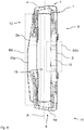
- Fig.2a shows the brake carrier Fig. 1 and Fig. 2 from a side-rotated view.
- Fig. 2a the arrangement of the first slope 15 of the application-side bridge strut 3 and the second slope 15a of the reaction-side bridge strut 3a on the side 14 of the brake carrier 1 facing away from the brake lining 20, 20a can be seen.
- the brake carrier horns 12, 12a, 12b, 12c for receiving the brake pads 20, 20a (cf. Fig. 1 ) of the brake carrier 1 can be seen.
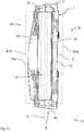
- Figure 2b shows the brake carrier 1 after Fig. 1 to Fig. 2a from the brake carrier underside 14, but in the removed state.
- an imaginary area B of the first bevel 15 is shown on the connection-side bridge strut 3 and an imaginary area B1 of the second bevel 15a is shown on the reaction-side bridge strut 3a.
- the areas B, B1 illustrate the arrangement of the bevels 15, 15a on the bridge struts 3, 3a.
- the first bevel 15 of the bridge strut 3 on the clamping side extends along from a third brake carrier horn 12b to a fourth brake carrier horn 12c.
- the second bevel 15a of the reaction-side bridge strut 3a extends along from a first brake carrier horn 12 to a second brake carrier horn 12a.
- Fig. 3 shows a brake carrier 1 after Figures 1 to 2b , in which the first bevel 15 of the tension-side bridge strut 3 and the second bevel 15a of the reaction-side bridge strut 3a are arranged between the first connecting web 4 and the second connecting web 4a.
- the arrangement of the first bevel 15 of the tension-side bridge strut 3 is marked for clarity by an imaginary area B3.
- the arrangement of the second bevel 15a of the reaction-side bridge strut 3, on the other hand, is marked with an imaginary area B4 for clarity.
- the bevels 15, 15a are arranged on the underside of the brake carrier side 14 of the bridge struts 3, 3a of the brake carrier 1 and make it difficult for deposits to penetrate into an interior 19 of the brake carrier 1.
- the first bevel 15 of the tension-side bridge strut 3 is namely arranged parallel to the brake carrier axis A over the entire length of the tension-side bridge strut 3.
- the second bevel 15a of the reaction-side bridge strut 3a is arranged parallel to the brake carrier axis A over the entire length of the reaction-side bridge strut 3a.
- a third variant of the brake carrier 1 shows Fig. 4.
- Fig. 4 shows the brake carrier 1 with a first connecting web 4 in cross section.
- the first bevel 15 of the bridge strut 3 on the tensioning side is, based on an imaginary first plane E in the direction of the brake disc 6 (see Fig. Fig. 1 ) of the brake carrier 1, tilted at an angle ⁇ of 5 °.
- the reaction-side bridge strut 3a is parallel, based on an imaginary second plane E2 in the direction of the brake disc 6 (see Fig. Fig. 1 ) of the brake carrier 1, tilted at an angle ⁇ of 3 °.
- the first bevel 15 of the bridge strut 3 on the tensioning side has a first nose 16.
- a second nose 16a is arranged on the second bevel 15a of the reaction-side bridge strut 3a.
- the first nose 16 of the first bevel 15 of the bridge strut 3 on the tensioning side is arranged in the direction of the brake carrier underside 14 in relation to an imaginary first plane E.
- the second nose 16a of the second bevel 15a of the reaction-side bridge strut 3a is also arranged in the direction of the brake carrier underside 14 in relation to an imaginary second plane E2.
- the lugs 16, 16a represent an additional limitation so that deposits which could penetrate the interior 19 of the brake carrier 1 from the outside ricochet off the lugs 16, 16a and are guided away from the brake disk 6 along the bevels 15, 15a.
- Fig. 5 shows the brake carrier 1 after Fig. 4 of the brake carrier underside 14.
- the continuous arrangement of the first nose 16 of the first bevel 15 of the tensioning-side bridge strut and the continuous arrangement of the second nose 16a of the second bevel 15a of the reaction-side bridge brace 3a are visible parallel in the direction of the brake carrier axis A.
- the first nose 16 of the first bevel 15 of the tension-side bridge strut 3 extends from the third brake carrier horn 12b to the fourth brake carrier horn 12c ( Fig.2a ).
- the second nose 16a of the second bevel 15a of the reaction-side bridge strut 3a extends from the first brake carrier horn 12 to the second brake carrier horn 12a ( Fig.2a ).
- the area of the first nose 16 of the first bevel 15 of the tension-side bridge strut 3 is shown by an imaginary area B5 and the second nose 16a of the second bevel 15a of the reaction-side bridge strut is shown by an imaginary area B6.
- Fig. 6 shows the brake carrier 1 after Fig. 4 in a laterally rotated perspective.
- the continuously arranged first nose 16 of the first bevel 15 of the tension-side bridge strut 3 is visible here, which extends from the third brake carrier horn 12b to the fourth brake carrier horn 12c.
- the continuous arranged second nose 16a of the second bevel 15a of the reaction-side bridge strut 3a is visible, which extends from the first brake carrier horn 12 extends to the second brake carrier horn 12a.
- Fig. 7 shows the area of the slopes 15, 15a of the brake carrier 1 Fig. 6 from the underside of the brake carrier 14.
- the first nose 16 of the first bevel 15 of the tension-side bridge strut 3 and the second nose 16a of the second bevel 15a of the reaction-side bridge strut 3a between the first connecting web 4 and the second connecting web 4a are continuously and without interruption.
- the area of the first nose 16 of the first bevel 15 of the tension-side bridge strut 3 is shown by an imaginary area B7 and that of the nose 16a of the second bevel 15a of the reaction-side bridge strut 3a is shown by an imaginary area B8.
- FIG. 8 Another embodiment of the brake carrier 1 according to Fig. 6 shows Fig. 8 .
- the second bevel 15a of the reaction-side bridge strut 3a is arranged continuously from a first connecting web 4 of the brake carrier 1 to a second connecting web 4a of the brake carrier 1.
- the connection-side bridge strut 3 is arranged continuously from a third brake carrier horn 12b to a fourth brake carrier horn 12c.
- An imaginary area B9 marks the second bevel 15a of the reaction-side bridge strut 3a.
- the first slope 15 of the bridge strut 3 on the tensioning side is illustrated by an imaginary area B10.
- Fig. 9 however shows a brake carrier 1 Fig. 6 , the first bevel 15 of the tension-side bridge strut 3 from a first connecting web 4 of the brake carrier 1 to a second Connecting web 4a of the brake carrier 1 is arranged continuously and the second bevel 15a of the reaction-side bridge strut 3a is arranged continuously from a first brake carrier horn 12 to a second brake carrier horn 12a.
- An imaginary area B11 illustrates the second bevel 15a of the reaction-side bridge strut 3a.
- the first bevel 15 of the bridge strut 3 on the tensioning side is illustrated by an imaginary area B12.
- Fig. 10 shows a further embodiment of the brake carrier 1 according to Fig. 6 .
- the connection-side bridge strut 3 of the brake carrier 1 has a first slope 15 and the reaction-side bridge strut 3a of the brake carrier 1 has a second slope 15a.
- a second nose 16a is arranged on the reaction-side bridge strut 3a.
- An imaginary area B13 illustrates the arrangement of the second bevel 15a of the reaction-side bridge strut 3a.
- the second bevel 15a and the second nose 16a of the reaction-side bridge strut 3a are arranged continuously from a first connecting web 4 of the brake carrier 1 to a second connecting web 4a of the brake carrier 1.
- the first bevel 15 of the bridge strut 3 on the application side is arranged continuously from a third brake carrier horn 12b of the brake carrier 1 to a fourth brake carrier horn 12c of the brake carrier 1.
- the first bevel 15 of the tension-side bridge strut 3 is illustrated by an imaginary area B14.
- Fig. 11 shows a brake carrier 1 after Fig. 6 , in which the tension-side bridge strut 3 has a first slope 15 and the reaction-side bridge strut 3a has a second slope 15a. Furthermore, on the tension-side bridge strut 3 is a first nose 16 arranged. Both the first bevel 15 of the engagement-side bridge strut 3 with the first nose 16 and the second bevel 15a of the reaction-side bridge strut 3a are arranged continuously from a first connecting web 4 of the brake carrier 1 to a second connecting web 4a of the brake carrier 1.
- An imaginary area B15 illustrates the second bevel 15a of the reaction-side bridge strut 3a. The first bevel 15 of the bridge strut 3 on the tensioning side with the first nose 16 is illustrated by an imaginary area B16.
- the imaginary area B15 shows the second bevel 15a of the reaction-side bridge strut 3a.
Landscapes
- Engineering & Computer Science (AREA)
- General Engineering & Computer Science (AREA)
- Mechanical Engineering (AREA)
- Braking Arrangements (AREA)
Claims (9)
- Support de frein (1) pour un frein à disque (2) doté d'un disque à frein (6), le support de frein (1) présentant une entretoise de pont côté application du frein (3) sur une face d'application du frein (9) du frein à disque (2) et une entretoise de pont côté réaction (3a) disposée en parallèle, par rapport à un axe de support de frein (A), sur une face de réaction (10) du frein à disque (2), dans lequel l'entretoise de pont côté application du frein (3) et l'entretoise de pont côté réaction (3a) sont reliées l'une à l'autre au niveau d'une première extrémité (7) du support de frein (1) par l'intermédiaire d'une première nervure de liaison (4), et l'entretoise de pont côté application du frein (3) et l'entretoise de pont côté réaction (3a) sont reliées l'une à l'autre au niveau d'une deuxième extrémité (8) du support de frein (1) par l'intermédiaire d'une deuxième nervure de liaison (4a), et le support de frein (1) présente une face de réception de garniture de frein (13) dotée de cornes de support de frein (12, 12a, 12b, 12c) et une face inférieure de support de frein (14) opposée à la face de réception de garniture de frein (13), caractérisé en ce que l'entretoise de pont côté application du frein (3) présente une première pente (15) sur la face inférieure de support de frein (14) du support de frein (1), et la première pente (15) de l'entretoise de pont côté application du frein (3) est disposée en continu en partant de la troisième corne de support de frein (12b) jusqu'à la quatrième corne de support de frein (12c), et l'entretoise de pont côté réaction (3a) présente une deuxième pente (15a) sur la face inférieure de support de frein (14) du support de frein (1), et la deuxième pente (15a) de l'entretoise de pont côté réaction (3a) est disposée en continu en partant de la première corne de support de frein (12) jusqu'à la deuxième corne de support de frein (12a).
- Support de frein (1) pour un frein à disque (2) selon la revendication 1, caractérisé en ce que l'inclinaison de la première pente (15) de l'entretoise de pont côté application du frein (3) et l'inclinaison de la deuxième pente (15a) de l'entretoise de pont côté réaction (3a) augmentent par rapport au côté détourné (14) du disque à frein (6) en direction de la garniture de frein (20, 20a).
- Support de frein (1) pour un frein à disque (2) selon la revendication 1 ou 2, caractérisé en ce que le support de frein (1) présente un premier plan imaginaire (E) et un deuxième plan imaginaire (E2), et la première pente (15) de l'entretoise de pont côté application du frein (3) est inclinée d'un angle (ex) par rapport au premier plan (E), et la deuxième pente (15a) de l'entretoise de pont côté réaction (3a) est inclinée d'un angle (β) par rapport au deuxième plan (E2) .
- Support de frein (1) pour un frein à disque (2) selon l'une quelconque des revendications précédentes, caractérisé en ce que la première pente (15) de l'entretoise de pont côté application du frein (3) est inclinée d'un angle (α) compris entre 1,5° et 15°, ou de préférence d'un angle (α) de 5°, et la deuxième pente (15a) de l'entretoise de pont côté réaction (3a) est inclinée d'un angle (β) compris entre 1,5° et 10°, ou de préférence d'un angle (β) de 3°.
- Support de frein (1) pour un frein à disque (2) selon l'une quelconque des revendications précédentes, caractérisé en ce que la première pente (15) de l'entretoise de pont côté application du frein (3) présente une première came (16) en parallèle à l'axe de support de frein (A), et/ou la deuxième pente (15a) de l'entretoise de pont côté réaction (3a) présente une deuxième came (16a) en parallèle à l'axe de support de frein (A).
- Support de frein (1) pour un frein à disque (2) selon la revendication 5, caractérisé en ce que la première came (16) de l'entretoise de pont côté application du frein (3) est réalisée d'un seul tenant avec le support de frein (1), et la deuxième came (16a) de l'entretoise de pont côté réaction (3a) est réalisée d'un seul tenant avec le support de frein (1).
- Support de frein (1) pour un frein à disque (2) selon l'une quelconque des revendications précédentes, caractérisé en ce que la première pente (15) de l'entretoise de pont côté application du frein (3) et la deuxième pente (15a) de l'entretoise de pont côté réaction (3a) sont disposées en continu entre la première nervure de liaison (4) et la deuxième nervure de liaison (4a).
- Support de frein (1) pour un frein à disque (2) selon l'une quelconque des revendications précédentes, caractérisé en ce que la première pente (15) de l'entretoise de pont côté application du frein (3) est disposée en continu, en partant de la troisième corne de support de frein (12b) jusqu'à la quatrième corne de support de frein (12c), et la deuxième pente (15a) de l'entretoise de pont côté réaction (3a) est disposée en continu entre la première nervure de liaison (4) et la deuxième nervure de liaison (4a).
- Support de frein (1) pour un frein à disque (2) selon l'une quelconque des revendications précédentes, caractérisé en ce que la première pente (15) de l'entretoise de pont côté application du frein (3) est disposée en continu entre la première nervure de liaison (4) et la deuxième nervure de liaison (4a), et la deuxième pente (15a) de l'entretoise de pont côté réaction (3a) est disposée en continu, en partant de la première corne de support de frein (12) jusqu'à la deuxième corne de support de frein (12a).
Applications Claiming Priority (1)
| Application Number | Priority Date | Filing Date | Title |
|---|---|---|---|
| DE102017011338.6A DE102017011338A1 (de) | 2017-12-08 | 2017-12-08 | Bremsträger für eine Scheibenbremse |
Publications (2)
| Publication Number | Publication Date |
|---|---|
| EP3495683A1 EP3495683A1 (fr) | 2019-06-12 |
| EP3495683B1 true EP3495683B1 (fr) | 2020-11-11 |
Family
ID=63642857
Family Applications (1)
| Application Number | Title | Priority Date | Filing Date |
|---|---|---|---|
| EP18195467.8A Active EP3495683B1 (fr) | 2017-12-08 | 2018-09-19 | Support de frein pour un frein à disque |
Country Status (3)
| Country | Link |
|---|---|
| US (1) | US11448273B2 (fr) |
| EP (1) | EP3495683B1 (fr) |
| DE (1) | DE102017011338A1 (fr) |
Families Citing this family (1)
| Publication number | Priority date | Publication date | Assignee | Title |
|---|---|---|---|---|
| EP3498395B1 (fr) * | 2017-12-13 | 2021-09-01 | Meritor Heavy Vehicle Braking Systems (UK) Limited | Coulée de support de frein et procédé de fabrication de coulée de support de frein |
Family Cites Families (13)
| Publication number | Priority date | Publication date | Assignee | Title |
|---|---|---|---|---|
| DE4036272A1 (de) * | 1990-11-14 | 1992-05-21 | Perrot Bremse Gmbh Deutsche | Gleitsattel-scheibenbremse |
| DE4343737B4 (de) | 1993-09-02 | 2005-11-17 | Deutsche Perrot-Bremse Gmbh | Scheibenbremse |
| JP4112067B2 (ja) * | 1998-03-31 | 2008-07-02 | 株式会社日立製作所 | ディスクブレーキ |
| DE29821643U1 (de) * | 1998-12-04 | 1999-02-11 | BPW Bergische Achsen KG, 51674 Wiehl | Fahrzeugbremse |
| GB0618416D0 (en) * | 2006-09-19 | 2006-11-01 | Spa | A brake carrier |
| GB2451690B (en) * | 2007-08-10 | 2009-08-05 | Ap Racing Ltd | A disc brake caliper body and a disc brake caliper comprising such a body |
| GB201009030D0 (en) * | 2010-06-01 | 2010-07-14 | Meritor Heavy Vehicle Braking | Disc brake |
| US20120067678A1 (en) * | 2010-09-21 | 2012-03-22 | Kelsey-Hayes Company | Anchor bracket for use in a disc brake assembly and method for making the same |
| DE102011103963B3 (de) * | 2011-06-10 | 2012-09-06 | Wabco Radbremsen Gmbh | Scheibenbremse, insbesondere für Nutzfahrzeuge |
| US9353810B2 (en) * | 2013-02-21 | 2016-05-31 | Kelsey-Hayes Company | Disc brake assembly with non-rotatable vehicle component and method for producing same |
| WO2015050638A1 (fr) * | 2013-10-02 | 2015-04-09 | Bendix Spicer Foundation Brake Llc | Système et procédé de montage et de maintien de plaquette de frein à disque |
| DE102013016312A1 (de) * | 2013-10-04 | 2015-04-09 | Knorr-Bremse Systeme für Nutzfahrzeuge GmbH | Scheibenbremse |
| DE102016104967A1 (de) * | 2015-10-09 | 2017-04-13 | Knorr-Bremse Systeme für Nutzfahrzeuge GmbH | Bremsträger |
-
2017
- 2017-12-08 DE DE102017011338.6A patent/DE102017011338A1/de not_active Withdrawn
-
2018
- 2018-09-19 EP EP18195467.8A patent/EP3495683B1/fr active Active
- 2018-12-03 US US16/207,272 patent/US11448273B2/en active Active
Non-Patent Citations (1)
| Title |
|---|
| None * |
Also Published As
| Publication number | Publication date |
|---|---|
| US11448273B2 (en) | 2022-09-20 |
| EP3495683A1 (fr) | 2019-06-12 |
| DE102017011338A1 (de) | 2019-06-13 |
| US20190178318A1 (en) | 2019-06-13 |
Similar Documents
| Publication | Publication Date | Title |
|---|---|---|
| DE60123644T2 (de) | Bremsvorrichtung, scheibenbremse, trommelbremse sowie verfahren zur herstellung einer bremsvorrichtung | |
| EP2245331A1 (fr) | Disque de frein | |
| EP2718582B1 (fr) | Frein à disque, en particulier pour véhicules utilitaires | |
| EP0341610A1 (fr) | Frein à disque à garniture partielle | |
| DE4208391A1 (de) | Motorradreifen | |
| DE102014112665A1 (de) | Bremsbelaghalterung einer Scheibenbremse, Scheibenbremse und Bremsbelag | |
| DE102013100162B4 (de) | Scheibenbremse für ein Nutzfahrzeug | |
| EP3495683B1 (fr) | Support de frein pour un frein à disque | |
| DE102009013358A1 (de) | Bremsscheibe für ein Fahrzeug sowie Verfahren zum Herstellen einer solchen | |
| EP0980989A2 (fr) | Frein à disque pour véhicules | |
| WO2020025307A1 (fr) | Support de garniture pour un système de fixation de garniture de frein d'un véhicule ferroviaire et système de fixation de garniture de frein | |
| DE3422878A1 (de) | Scheibenbremse | |
| DE102019103300B4 (de) | Fahrzeugrad Isolator | |
| DE102007020572A1 (de) | Bremsbelag für eine Scheibenbremse | |
| DE8519567U1 (de) | Scheibenbremse mit Bremssattel und durch Haken im Bremssattel befestigten Bremsbelägen | |
| EP0984188B1 (fr) | Frein à disque à garniture partielle | |
| DE102015212017A1 (de) | Bremstrommel | |
| DE102015121942A1 (de) | Scheibenbremse für ein Nutzfahrzeug sowie Bremsbelag für eine Scheibenbremse | |
| DE102014113369A1 (de) | Anordnung eines Bremsträgers einer Scheibenbremse an einer Fahrzeugachse, Bremsträger und Scheibenbremse | |
| DE60122726T2 (de) | Bremselement, scheibenbremse, trommelbremse | |
| EP0976581B1 (fr) | Dispositif de fixation pour roues ferroviaires et méthode correspondante pour fixer | |
| DE112015004926B4 (de) | Bremse | |
| DE10297013T5 (de) | Buchse für eine Scheibenbremse | |
| DE29823591U1 (de) | Scheibenbremse für Fahrzeuge | |
| DE102020125134A1 (de) | Räumleiste für den Räumschild eines Schneepfluges |
Legal Events
| Date | Code | Title | Description |
|---|---|---|---|
| PUAI | Public reference made under article 153(3) epc to a published international application that has entered the european phase |
Free format text: ORIGINAL CODE: 0009012 |
|
| STAA | Information on the status of an ep patent application or granted ep patent |
Free format text: STATUS: THE APPLICATION HAS BEEN PUBLISHED |
|
| AK | Designated contracting states |
Kind code of ref document: A1 Designated state(s): AL AT BE BG CH CY CZ DE DK EE ES FI FR GB GR HR HU IE IS IT LI LT LU LV MC MK MT NL NO PL PT RO RS SE SI SK SM TR |
|
| AX | Request for extension of the european patent |
Extension state: BA ME |
|
| STAA | Information on the status of an ep patent application or granted ep patent |
Free format text: STATUS: REQUEST FOR EXAMINATION WAS MADE |
|
| 17P | Request for examination filed |
Effective date: 20191212 |
|
| RBV | Designated contracting states (corrected) |
Designated state(s): AL AT BE BG CH CY CZ DE DK EE ES FI FR GB GR HR HU IE IS IT LI LT LU LV MC MK MT NL NO PL PT RO RS SE SI SK SM TR |
|
| RIC1 | Information provided on ipc code assigned before grant |
Ipc: F16D 65/00 20060101AFI20200406BHEP |
|
| GRAP | Despatch of communication of intention to grant a patent |
Free format text: ORIGINAL CODE: EPIDOSNIGR1 |
|
| STAA | Information on the status of an ep patent application or granted ep patent |
Free format text: STATUS: GRANT OF PATENT IS INTENDED |
|
| INTG | Intention to grant announced |
Effective date: 20200629 |
|
| GRAS | Grant fee paid |
Free format text: ORIGINAL CODE: EPIDOSNIGR3 |
|
| GRAA | (expected) grant |
Free format text: ORIGINAL CODE: 0009210 |
|
| STAA | Information on the status of an ep patent application or granted ep patent |
Free format text: STATUS: THE PATENT HAS BEEN GRANTED |
|
| AK | Designated contracting states |
Kind code of ref document: B1 Designated state(s): AL AT BE BG CH CY CZ DE DK EE ES FI FR GB GR HR HU IE IS IT LI LT LU LV MC MK MT NL NO PL PT RO RS SE SI SK SM TR |
|
| REG | Reference to a national code |
Ref country code: GB Ref legal event code: FG4D Free format text: NOT ENGLISH |
|
| REG | Reference to a national code |
Ref country code: CH Ref legal event code: EP |
|
| REG | Reference to a national code |
Ref country code: AT Ref legal event code: REF Ref document number: 1333771 Country of ref document: AT Kind code of ref document: T Effective date: 20201115 |
|
| REG | Reference to a national code |
Ref country code: DE Ref legal event code: R096 Ref document number: 502018002985 Country of ref document: DE |
|
| REG | Reference to a national code |
Ref country code: IE Ref legal event code: FG4D Free format text: LANGUAGE OF EP DOCUMENT: GERMAN |
|
| REG | Reference to a national code |
Ref country code: NL Ref legal event code: MP Effective date: 20201111 |
|
| PG25 | Lapsed in a contracting state [announced via postgrant information from national office to epo] |
Ref country code: GR Free format text: LAPSE BECAUSE OF FAILURE TO SUBMIT A TRANSLATION OF THE DESCRIPTION OR TO PAY THE FEE WITHIN THE PRESCRIBED TIME-LIMIT Effective date: 20210212 Ref country code: NO Free format text: LAPSE BECAUSE OF FAILURE TO SUBMIT A TRANSLATION OF THE DESCRIPTION OR TO PAY THE FEE WITHIN THE PRESCRIBED TIME-LIMIT Effective date: 20210211 Ref country code: FI Free format text: LAPSE BECAUSE OF FAILURE TO SUBMIT A TRANSLATION OF THE DESCRIPTION OR TO PAY THE FEE WITHIN THE PRESCRIBED TIME-LIMIT Effective date: 20201111 Ref country code: RS Free format text: LAPSE BECAUSE OF FAILURE TO SUBMIT A TRANSLATION OF THE DESCRIPTION OR TO PAY THE FEE WITHIN THE PRESCRIBED TIME-LIMIT Effective date: 20201111 Ref country code: PT Free format text: LAPSE BECAUSE OF FAILURE TO SUBMIT A TRANSLATION OF THE DESCRIPTION OR TO PAY THE FEE WITHIN THE PRESCRIBED TIME-LIMIT Effective date: 20210311 |
|
| RAP4 | Party data changed (patent owner data changed or rights of a patent transferred) |
Owner name: ZF CV SYSTEMS EUROPE BV |
|
| PG25 | Lapsed in a contracting state [announced via postgrant information from national office to epo] |
Ref country code: BG Free format text: LAPSE BECAUSE OF FAILURE TO SUBMIT A TRANSLATION OF THE DESCRIPTION OR TO PAY THE FEE WITHIN THE PRESCRIBED TIME-LIMIT Effective date: 20210211 Ref country code: SE Free format text: LAPSE BECAUSE OF FAILURE TO SUBMIT A TRANSLATION OF THE DESCRIPTION OR TO PAY THE FEE WITHIN THE PRESCRIBED TIME-LIMIT Effective date: 20201111 Ref country code: PL Free format text: LAPSE BECAUSE OF FAILURE TO SUBMIT A TRANSLATION OF THE DESCRIPTION OR TO PAY THE FEE WITHIN THE PRESCRIBED TIME-LIMIT Effective date: 20201111 Ref country code: IS Free format text: LAPSE BECAUSE OF FAILURE TO SUBMIT A TRANSLATION OF THE DESCRIPTION OR TO PAY THE FEE WITHIN THE PRESCRIBED TIME-LIMIT Effective date: 20210311 Ref country code: LV Free format text: LAPSE BECAUSE OF FAILURE TO SUBMIT A TRANSLATION OF THE DESCRIPTION OR TO PAY THE FEE WITHIN THE PRESCRIBED TIME-LIMIT Effective date: 20201111 |
|
| REG | Reference to a national code |
Ref country code: LT Ref legal event code: MG9D |
|
| PG25 | Lapsed in a contracting state [announced via postgrant information from national office to epo] |
Ref country code: HR Free format text: LAPSE BECAUSE OF FAILURE TO SUBMIT A TRANSLATION OF THE DESCRIPTION OR TO PAY THE FEE WITHIN THE PRESCRIBED TIME-LIMIT Effective date: 20201111 |
|
| PG25 | Lapsed in a contracting state [announced via postgrant information from national office to epo] |
Ref country code: LT Free format text: LAPSE BECAUSE OF FAILURE TO SUBMIT A TRANSLATION OF THE DESCRIPTION OR TO PAY THE FEE WITHIN THE PRESCRIBED TIME-LIMIT Effective date: 20201111 Ref country code: SK Free format text: LAPSE BECAUSE OF FAILURE TO SUBMIT A TRANSLATION OF THE DESCRIPTION OR TO PAY THE FEE WITHIN THE PRESCRIBED TIME-LIMIT Effective date: 20201111 Ref country code: RO Free format text: LAPSE BECAUSE OF FAILURE TO SUBMIT A TRANSLATION OF THE DESCRIPTION OR TO PAY THE FEE WITHIN THE PRESCRIBED TIME-LIMIT Effective date: 20201111 Ref country code: SM Free format text: LAPSE BECAUSE OF FAILURE TO SUBMIT A TRANSLATION OF THE DESCRIPTION OR TO PAY THE FEE WITHIN THE PRESCRIBED TIME-LIMIT Effective date: 20201111 Ref country code: CZ Free format text: LAPSE BECAUSE OF FAILURE TO SUBMIT A TRANSLATION OF THE DESCRIPTION OR TO PAY THE FEE WITHIN THE PRESCRIBED TIME-LIMIT Effective date: 20201111 Ref country code: EE Free format text: LAPSE BECAUSE OF FAILURE TO SUBMIT A TRANSLATION OF THE DESCRIPTION OR TO PAY THE FEE WITHIN THE PRESCRIBED TIME-LIMIT Effective date: 20201111 |
|
| REG | Reference to a national code |
Ref country code: DE Ref legal event code: R097 Ref document number: 502018002985 Country of ref document: DE |
|
| PG25 | Lapsed in a contracting state [announced via postgrant information from national office to epo] |
Ref country code: DK Free format text: LAPSE BECAUSE OF FAILURE TO SUBMIT A TRANSLATION OF THE DESCRIPTION OR TO PAY THE FEE WITHIN THE PRESCRIBED TIME-LIMIT Effective date: 20201111 |
|
| REG | Reference to a national code |
Ref country code: DE Ref legal event code: R081 Ref document number: 502018002985 Country of ref document: DE Owner name: ZF CV SYSTEMS EUROPE BV, BE Free format text: FORMER OWNER: WABCO EUROPE BVBA, BRUESSEL, BE |
|
| PLBE | No opposition filed within time limit |
Free format text: ORIGINAL CODE: 0009261 |
|
| STAA | Information on the status of an ep patent application or granted ep patent |
Free format text: STATUS: NO OPPOSITION FILED WITHIN TIME LIMIT |
|
| 26N | No opposition filed |
Effective date: 20210812 |
|
| PG25 | Lapsed in a contracting state [announced via postgrant information from national office to epo] |
Ref country code: IT Free format text: LAPSE BECAUSE OF FAILURE TO SUBMIT A TRANSLATION OF THE DESCRIPTION OR TO PAY THE FEE WITHIN THE PRESCRIBED TIME-LIMIT Effective date: 20201111 Ref country code: AL Free format text: LAPSE BECAUSE OF FAILURE TO SUBMIT A TRANSLATION OF THE DESCRIPTION OR TO PAY THE FEE WITHIN THE PRESCRIBED TIME-LIMIT Effective date: 20201111 Ref country code: NL Free format text: LAPSE BECAUSE OF FAILURE TO SUBMIT A TRANSLATION OF THE DESCRIPTION OR TO PAY THE FEE WITHIN THE PRESCRIBED TIME-LIMIT Effective date: 20201111 |
|
| PG25 | Lapsed in a contracting state [announced via postgrant information from national office to epo] |
Ref country code: SI Free format text: LAPSE BECAUSE OF FAILURE TO SUBMIT A TRANSLATION OF THE DESCRIPTION OR TO PAY THE FEE WITHIN THE PRESCRIBED TIME-LIMIT Effective date: 20201111 |
|
| PG25 | Lapsed in a contracting state [announced via postgrant information from national office to epo] |
Ref country code: ES Free format text: LAPSE BECAUSE OF FAILURE TO SUBMIT A TRANSLATION OF THE DESCRIPTION OR TO PAY THE FEE WITHIN THE PRESCRIBED TIME-LIMIT Effective date: 20201111 |
|
| REG | Reference to a national code |
Ref country code: CH Ref legal event code: PL |
|
| REG | Reference to a national code |
Ref country code: BE Ref legal event code: MM Effective date: 20210930 |
|
| PG25 | Lapsed in a contracting state [announced via postgrant information from national office to epo] |
Ref country code: IS Free format text: LAPSE BECAUSE OF FAILURE TO SUBMIT A TRANSLATION OF THE DESCRIPTION OR TO PAY THE FEE WITHIN THE PRESCRIBED TIME-LIMIT Effective date: 20210311 Ref country code: MC Free format text: LAPSE BECAUSE OF FAILURE TO SUBMIT A TRANSLATION OF THE DESCRIPTION OR TO PAY THE FEE WITHIN THE PRESCRIBED TIME-LIMIT Effective date: 20201111 |
|
| PG25 | Lapsed in a contracting state [announced via postgrant information from national office to epo] |
Ref country code: LU Free format text: LAPSE BECAUSE OF NON-PAYMENT OF DUE FEES Effective date: 20210919 Ref country code: IE Free format text: LAPSE BECAUSE OF NON-PAYMENT OF DUE FEES Effective date: 20210919 Ref country code: FR Free format text: LAPSE BECAUSE OF NON-PAYMENT OF DUE FEES Effective date: 20210930 Ref country code: BE Free format text: LAPSE BECAUSE OF NON-PAYMENT OF DUE FEES Effective date: 20210930 |
|
| PG25 | Lapsed in a contracting state [announced via postgrant information from national office to epo] |
Ref country code: LI Free format text: LAPSE BECAUSE OF NON-PAYMENT OF DUE FEES Effective date: 20210930 Ref country code: CH Free format text: LAPSE BECAUSE OF NON-PAYMENT OF DUE FEES Effective date: 20210930 |
|
| GBPC | Gb: european patent ceased through non-payment of renewal fee |
Effective date: 20220919 |
|
| PG25 | Lapsed in a contracting state [announced via postgrant information from national office to epo] |
Ref country code: CY Free format text: LAPSE BECAUSE OF FAILURE TO SUBMIT A TRANSLATION OF THE DESCRIPTION OR TO PAY THE FEE WITHIN THE PRESCRIBED TIME-LIMIT Effective date: 20201111 |
|
| P01 | Opt-out of the competence of the unified patent court (upc) registered |
Effective date: 20230528 |
|
| PG25 | Lapsed in a contracting state [announced via postgrant information from national office to epo] |
Ref country code: HU Free format text: LAPSE BECAUSE OF FAILURE TO SUBMIT A TRANSLATION OF THE DESCRIPTION OR TO PAY THE FEE WITHIN THE PRESCRIBED TIME-LIMIT; INVALID AB INITIO Effective date: 20180919 |
|
| PG25 | Lapsed in a contracting state [announced via postgrant information from national office to epo] |
Ref country code: GB Free format text: LAPSE BECAUSE OF NON-PAYMENT OF DUE FEES Effective date: 20220919 |
|
| PG25 | Lapsed in a contracting state [announced via postgrant information from national office to epo] |
Ref country code: MK Free format text: LAPSE BECAUSE OF FAILURE TO SUBMIT A TRANSLATION OF THE DESCRIPTION OR TO PAY THE FEE WITHIN THE PRESCRIBED TIME-LIMIT Effective date: 20201111 |
|
| PG25 | Lapsed in a contracting state [announced via postgrant information from national office to epo] |
Ref country code: MT Free format text: LAPSE BECAUSE OF FAILURE TO SUBMIT A TRANSLATION OF THE DESCRIPTION OR TO PAY THE FEE WITHIN THE PRESCRIBED TIME-LIMIT Effective date: 20201111 |
|
| REG | Reference to a national code |
Ref country code: AT Ref legal event code: MM01 Ref document number: 1333771 Country of ref document: AT Kind code of ref document: T Effective date: 20230919 |
|
| PG25 | Lapsed in a contracting state [announced via postgrant information from national office to epo] |
Ref country code: AT Free format text: LAPSE BECAUSE OF NON-PAYMENT OF DUE FEES Effective date: 20230919 |
|
| PG25 | Lapsed in a contracting state [announced via postgrant information from national office to epo] |
Ref country code: AT Free format text: LAPSE BECAUSE OF NON-PAYMENT OF DUE FEES Effective date: 20230919 |
|
| PGFP | Annual fee paid to national office [announced via postgrant information from national office to epo] |
Ref country code: DE Payment date: 20250702 Year of fee payment: 8 |
|
| PG25 | Lapsed in a contracting state [announced via postgrant information from national office to epo] |
Ref country code: TR Free format text: LAPSE BECAUSE OF FAILURE TO SUBMIT A TRANSLATION OF THE DESCRIPTION OR TO PAY THE FEE WITHIN THE PRESCRIBED TIME-LIMIT Effective date: 20201111 |
|
| PGFP | Annual fee paid to national office [announced via postgrant information from national office to epo] |
Ref country code: AT Payment date: 20260410 Year of fee payment: 5 |