EP3495984A1 - Lecteur de carte protégé contre la manipulation doté d'un couvercle de protection d'alésage - Google Patents
Lecteur de carte protégé contre la manipulation doté d'un couvercle de protection d'alésage Download PDFInfo
- Publication number
- EP3495984A1 EP3495984A1 EP17205467.8A EP17205467A EP3495984A1 EP 3495984 A1 EP3495984 A1 EP 3495984A1 EP 17205467 A EP17205467 A EP 17205467A EP 3495984 A1 EP3495984 A1 EP 3495984A1
- Authority
- EP
- European Patent Office
- Prior art keywords
- card reader
- conductor track
- conductor
- foil
- bohrschutzabdeckung
- Prior art date
- Legal status (The legal status is an assumption and is not a legal conclusion. Google has not performed a legal analysis and makes no representation as to the accuracy of the status listed.)
- Withdrawn
Links
Images

Classifications
-
- G—PHYSICS
- G06—COMPUTING OR CALCULATING; COUNTING
- G06K—GRAPHICAL DATA READING; PRESENTATION OF DATA; RECORD CARRIERS; HANDLING RECORD CARRIERS
- G06K7/00—Methods or arrangements for sensing record carriers, e.g. for reading patterns
- G06K7/0013—Methods or arrangements for sensing record carriers, e.g. for reading patterns by galvanic contacts, e.g. card connectors for ISO-7816 compliant smart cards or memory cards, e.g. SD card readers
- G06K7/0056—Methods or arrangements for sensing record carriers, e.g. for reading patterns by galvanic contacts, e.g. card connectors for ISO-7816 compliant smart cards or memory cards, e.g. SD card readers housing of the card connector
- G06K7/0078—Methods or arrangements for sensing record carriers, e.g. for reading patterns by galvanic contacts, e.g. card connectors for ISO-7816 compliant smart cards or memory cards, e.g. SD card readers housing of the card connector reinforced housing for protection against damage, be it due malevolent action, such as drilling and other ways of forced entry, or by accident, such as shock due to dropping
-
- G—PHYSICS
- G06—COMPUTING OR CALCULATING; COUNTING
- G06K—GRAPHICAL DATA READING; PRESENTATION OF DATA; RECORD CARRIERS; HANDLING RECORD CARRIERS
- G06K7/00—Methods or arrangements for sensing record carriers, e.g. for reading patterns
- G06K7/0013—Methods or arrangements for sensing record carriers, e.g. for reading patterns by galvanic contacts, e.g. card connectors for ISO-7816 compliant smart cards or memory cards, e.g. SD card readers
- G06K7/0021—Methods or arrangements for sensing record carriers, e.g. for reading patterns by galvanic contacts, e.g. card connectors for ISO-7816 compliant smart cards or memory cards, e.g. SD card readers for reading/sensing record carriers having surface contacts
-
- G—PHYSICS
- G06—COMPUTING OR CALCULATING; COUNTING
- G06K—GRAPHICAL DATA READING; PRESENTATION OF DATA; RECORD CARRIERS; HANDLING RECORD CARRIERS
- G06K7/00—Methods or arrangements for sensing record carriers, e.g. for reading patterns
- G06K7/0013—Methods or arrangements for sensing record carriers, e.g. for reading patterns by galvanic contacts, e.g. card connectors for ISO-7816 compliant smart cards or memory cards, e.g. SD card readers
- G06K7/0086—Methods or arrangements for sensing record carriers, e.g. for reading patterns by galvanic contacts, e.g. card connectors for ISO-7816 compliant smart cards or memory cards, e.g. SD card readers the connector comprising a circuit for steering the operations of the card connector
- G06K7/0091—Methods or arrangements for sensing record carriers, e.g. for reading patterns by galvanic contacts, e.g. card connectors for ISO-7816 compliant smart cards or memory cards, e.g. SD card readers the connector comprising a circuit for steering the operations of the card connector the circuit comprising an arrangement for avoiding intrusions and unwanted access to data inside of the connector
Definitions
- the present invention relates to a card reader having a contacting unit for exchanging data with a chip card and a plastic Bohrschutzabdeckung covering the contacting and / or an electronic component connected thereto with a plastic-coated printed circuit board film, which has a nationwide Bohrtik conductor track structure, as well as a Bohrtikabdeckung made of plastic, in particular Bohrschutzhaube, with a plastic injection molded conductor sheet, which has a nationwide drilling protection track structure.
- a card reader with such a cover is for example by the EP 3 196 799 A1 known.
- This known card reader has a plastic injection-molded part in the form of a drill protection hood with a drill protection conductor track structure provided thereon.
- the Bohrschutzhaube is an injection-molded plastic part, the inside of which is back-injected with a two-ply conductor foil, which has a nationwide Bohrschutz conductor track structure with at least one continuous electrical conductor track.
- the conductor foil is integrally connected or fused to the plastic material of the drill protection hood. If the Bohrschutzhaube is pierced or abraded for manipulation purposes, thereby also the continuous trace is severed, over which a current flows during operation. This circuit interruption is detected by a monitoring unit, which then no longer permits read operation or deactivates the contactor unit.
- the conductor foil has a single-layer or multi-layer drilling protection conductor track structure, which can be applied, in particular printed, to a carrier layer or an intermediate layer of the conductor track foil.
- Transparent or clear electrically conductive ink is sold, for example, by Nanolntegris Technologies, Inc., by Henkel under the name Loctite ECI 5000 and by Applied Ink Solutions under the brand name Orga-Con TM.
- These known inks contain, for example, electrically conductive polymers or silver nanowires.
- transparent electrically conductive structures can be printed up to a resolution of 100 ⁇ m on flexible and rigid substrates of eg PET, PC, PMMA, PI or glass.
- the trace (s) of the printed drill protection trace structure are not visible to a viewer and prevent the gap between two traces from being noticeable, thus even more effectively avoiding the undetected drilling of the bore shield trace structure energized during operation.
- the conductor film advantageously forms the side of the Bohrtikabdeckung facing the contacting or the electronic component, so that only the plastic of the Bohrtikabdeckung should be removed (sanded) in order to get to the conductor film at all.
- the at least one drill protection conductor track has a line width of at most 0.2 mm, in particular at most 0.15 mm, and a line spacing of at most 0.3 mm, in particular at most 0.2 mm.
- the card reader may be mounted on a printed circuit board which electrically contacts the drill protection trace structure.
- the at least one drill protection conductor track preferably has electrical connection contacts at its two ends, in particular in the form of exposed electrical contact surfaces, which are contacted by electrical mating contacts of the card reader, which in turn can be connected to a monitoring unit.
- the Bohrschutzabdeckung is designed as Bohrschutzhaube whose Dome inside or outside is formed by the conductor foil.
- the contacting unit can be completely covered by the drill protection hood.
- the invention also relates to a plastic drill protection cover for protecting electronic components or data lines with a plastic-coated printed circuit board foil which has a nationwide drill protection printed circuit trace structure, which according to the invention has an electrically conductive, transparent ink applied to the conductor foil, in particular imprinted.
- the conductor foil has a single-layer or multi-layer drill protection conductor track structure which is applied, in particular printed, to a carrier layer or an intermediate layer of the conductor track foil.
- the electronic components may be, for example, processors that encrypt the data to be exchanged, and act on the data lines to electrical lines.
- the Bohrschutz-Leiterbahn founded has at least one Bohrschutz conductor track with a line thickness of at most 0.2 mm, in particular at most 0.15 mm, and with a line spacing of at most 0.3 mm, in particular at most 0.2 mm.
- the at least one drill protection conductor track each have electrical connection contacts at its two ends, in particular in the form of exposed electrical contact surfaces.
- the Bohrtikabdeckung is designed as Bohrschutzhaube whose Dome inside and / or outside is formed by the conductor foil.
- the in Fig. 1 shown card reader 1 is a so-called push / pull card reader, in which a smart card 2 inserted by the user in the insertion direction 3 via a Receiveein Fighting Anlagen réelle 4 in the card slot of a contact carrier 5 (or a card reader housing) to the data exchange position and after the data exchange from the user is pulled out of the card reader 1 again.
- the smart card 2 carries a microchip (not shown) for storing the data, the contacts of which are provided as electrical contact pads (not shown) on the card surface.
- a contacting unit 6 is arranged for data exchange with the chip card 2 inserted into the card slot through the card insertion opening 4.
- the contacting unit 6 has a plurality of elastically deformable contact springs 7 , which protrude with their free contact ends in the card path. As a result of the inserted chip card 2, the free contact ends of the contact springs 7 are deflected out of the card path and contact the electrical contact fields of the chip card 2.
- the contact carrier 5 together with the contacting unit 6 is covered on the underside by a drill protection cover made of plastic in the form of a drill protection hood 8 , the inside of the hood being formed by a plastic-coated conductor foil 9 ( Fig. 2 ).
- the contact carrier 5 is inserted accurately positioned in the Bohrschutzhaube 8 and attached thereto.
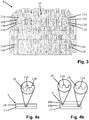
- the flexible conductor foil 9 is in Fig. 3 shown as a flat foil blank.
- At least one blanket protection strip conductor structure 10 in the form of four meandering protection strips 11a-11d is printed on the strip conductor 9 with a transparent, electrically conductive ink having a line width of at most 0.2 mm and a line spacing of at most 0.3 mm. by virtue of the transparent ink, the printed Bohrschutz-Leiterbahn Modell 10 or their Bohrschutz tracks 11a-11d are not visible to a viewer.
- Two drill protection tracks 11a, 11b are located on the in Fig. 3 left half and two anti-drilling conductor tracks 11c, 11d are arranged on the right half of the conductor foil 9.
- the erected conductor sheet 9 is inserted into the injection mold of the Bohrschutzhaube 8, wherein the side walls of the erected conductor sheet 9 overlap each other, so that the erected conductor sheet 9 area-comprehensive a seamless Bohrschutz conductor track structure 10 has.
- the conductor film 9 is back-injected with plastic, which then forms the inside of the hood, as in Fig. 2 is shown.
- Each of the four printed drill protection printed circuit traces 11a-11d has at its two ends two connection contacts 12a-12d in the form of exposed electrical contact surfaces on the inside of the hood.
- four mating contacts 13 are mounted in the form of double contact pads, which each contact two of the total of eight terminals 12a-12d of Bohrschutzhaube 8.
- the mating contacts 13 are guided laterally next to the contact carrier 5 up to above the contact carrier 5.
- the Bohrschutzhaube 8 including Mixierech 6 is attached to the underside of a printed circuit board indicated by dash-dot lines 14 , precisely by means of Positioniervorsprüngen 15 on the contact carrier 5 and the Bohrschutzhaube 8, which engage in corresponding openings of the circuit board 14.
- the Bohrtikhaube 8 is bolted to the circuit board 14 via screws that go through holes 16 in the four corners of Bohrschutzhaube 8.
- the conductor foil 9 may have a single-layer drill protection strip conductor structure 10 with one or more drill protection strip conductors 11a, 11b, which are printed with the transparent ink on a carrier layer 17 of the strip conductor film 9.
- the printed side of the carrier layer 17 is covered with a protective layer 18 , so that during injection molding of the Bohrschutzhaube 8 the Bohrschutz-conductor tracks 11a, 11b are protected and one of the two layers 17, 18 is firmly bonded to the plastic.
- the conductor film 9 has a two-layer drill protection conductor track structure 10, each having one or more drill protection conductor tracks 11a, 11b.
- a Bohrschutz- conductor 11a (or more), which are covered with a first, inner protective layer 18a .
- this inner protective layer 18a is printed, with the transparent ink, a tamper-resistant conductive trace 11b (or more) covered with a second outer protective layer 18b .
- the Bohrschutz interconnects 11a, 11b protected and the carrier or outer protective layer 17, 18b is firmly bonded to the plastic.
- the drill protection hood 8 If, for manipulation purposes, the drill protection hood 8 is pierced or ground off from the outside, this inevitably destroys its invisible drill protection conductor track structure 10 over which a current flows during operation, and consequently the circuit which has been closed up to that point is interrupted. This is detected by a monitoring unit (not shown) of the printed circuit board 14, which then no longer permits read operation or deactivates the contacting unit 6. If the Bohrschutzhaube 8 is lifted off the circuit board 14 for manipulation purposes, the electrical contact between the terminals 12a-12d of the Bohrschutzhaube 8 and the mating contacts 13 of the contact carrier 5 is inevitably interrupted and consequently interrupted until then closed circuit. This is also detected by the monitoring unit, which then no longer permits reading or the contacting unit 6 is disabled. An unnoticed manipulation of the card reader 1 is thus not possible, whereby a "secure card reader" is provided.
Landscapes
- Engineering & Computer Science (AREA)
- Artificial Intelligence (AREA)
- Computer Vision & Pattern Recognition (AREA)
- Physics & Mathematics (AREA)
- General Physics & Mathematics (AREA)
- Theoretical Computer Science (AREA)
- Structure Of Printed Boards (AREA)
- Credit Cards Or The Like (AREA)
Priority Applications (2)
| Application Number | Priority Date | Filing Date | Title |
|---|---|---|---|
| EP17205467.8A EP3495984A1 (fr) | 2017-12-05 | 2017-12-05 | Lecteur de carte protégé contre la manipulation doté d'un couvercle de protection d'alésage |
| US16/208,865 US20190171851A1 (en) | 2017-12-05 | 2018-12-04 | Tamper-proof card reader with a drilling protection cover |
Applications Claiming Priority (1)
| Application Number | Priority Date | Filing Date | Title |
|---|---|---|---|
| EP17205467.8A EP3495984A1 (fr) | 2017-12-05 | 2017-12-05 | Lecteur de carte protégé contre la manipulation doté d'un couvercle de protection d'alésage |
Publications (1)
| Publication Number | Publication Date |
|---|---|
| EP3495984A1 true EP3495984A1 (fr) | 2019-06-12 |
Family
ID=60629465
Family Applications (1)
| Application Number | Title | Priority Date | Filing Date |
|---|---|---|---|
| EP17205467.8A Withdrawn EP3495984A1 (fr) | 2017-12-05 | 2017-12-05 | Lecteur de carte protégé contre la manipulation doté d'un couvercle de protection d'alésage |
Country Status (2)
| Country | Link |
|---|---|
| US (1) | US20190171851A1 (fr) |
| EP (1) | EP3495984A1 (fr) |
Citations (4)
| Publication number | Priority date | Publication date | Assignee | Title |
|---|---|---|---|---|
| EP2047414A2 (fr) * | 2006-08-03 | 2009-04-15 | Smart Packaging Solutions (SPS) | Document sécurisé, notamment passeport électronique à sécurité renforcée |
| DE202014101751U1 (de) * | 2014-04-14 | 2014-04-24 | Johnson Electric S.A. | Sicherheitshülle mit zerreißbarem Substrat |
| EP2950234A1 (fr) * | 2014-05-27 | 2015-12-02 | ddm hopt + schuler GmbH & Co. KG. | Lecteur de carte protégé contre la manipulation doté d'une structure à pistes conductives imprimées anti-perçage |
| EP3196799A1 (fr) | 2016-01-25 | 2017-07-26 | ddm hopt + schuler GmbH & Co. KG. | Lecteur de carte protege contre la manipulation dote d'un couvercle presentant un circuit imprime double-couche moule |
Family Cites Families (8)
| Publication number | Priority date | Publication date | Assignee | Title |
|---|---|---|---|---|
| DE102006039136A1 (de) * | 2005-09-13 | 2007-03-15 | Amphenol-Tuchel Electronics Gmbh | Manipulations- und Durchbohrschutz für Smart Card Reader |
| EP1873680A1 (fr) * | 2006-06-23 | 2008-01-02 | ddm hopt + schuler GmbH & Co. KG. | Lecteur de carte protégé contre la manipulation |
| FR2909469B1 (fr) * | 2006-12-01 | 2009-01-02 | Itt Mfg Enterprises Inc | Agencement de securite contre la fraude pour connecteur electrique pour carte a puce |
| EP2000945B1 (fr) * | 2007-06-01 | 2010-08-04 | ddm hopt + schuler GmbH & Co. KG. | Lecteur de carte protégé contre la manipulation |
| US9298956B2 (en) * | 2013-10-04 | 2016-03-29 | Square, Inc. | Tamper protection mesh in an electronic device |
| US9342717B2 (en) * | 2014-02-26 | 2016-05-17 | Ncr Corporation | Tamper detection system and method |
| FR3043231B1 (fr) * | 2015-11-03 | 2017-12-22 | Ingenico Group | Corps de lecteur de carte a memoire a treillis de protection recto-verso |
| US10019607B2 (en) * | 2016-01-25 | 2018-07-10 | Ddm Hopt + Schuler Gmbh & Co. Kg | Manipulation-proof card reader with a covering hood which has a back-moulded double-layered conductor track foil |
-
2017
- 2017-12-05 EP EP17205467.8A patent/EP3495984A1/fr not_active Withdrawn
-
2018
- 2018-12-04 US US16/208,865 patent/US20190171851A1/en not_active Abandoned
Patent Citations (4)
| Publication number | Priority date | Publication date | Assignee | Title |
|---|---|---|---|---|
| EP2047414A2 (fr) * | 2006-08-03 | 2009-04-15 | Smart Packaging Solutions (SPS) | Document sécurisé, notamment passeport électronique à sécurité renforcée |
| DE202014101751U1 (de) * | 2014-04-14 | 2014-04-24 | Johnson Electric S.A. | Sicherheitshülle mit zerreißbarem Substrat |
| EP2950234A1 (fr) * | 2014-05-27 | 2015-12-02 | ddm hopt + schuler GmbH & Co. KG. | Lecteur de carte protégé contre la manipulation doté d'une structure à pistes conductives imprimées anti-perçage |
| EP3196799A1 (fr) | 2016-01-25 | 2017-07-26 | ddm hopt + schuler GmbH & Co. KG. | Lecteur de carte protege contre la manipulation dote d'un couvercle presentant un circuit imprime double-couche moule |
Also Published As
| Publication number | Publication date |
|---|---|
| US20190171851A1 (en) | 2019-06-06 |
Similar Documents
| Publication | Publication Date | Title |
|---|---|---|
| DE3535791C2 (fr) | ||
| DE69011223T2 (de) | Verbinderanordnung mit einem beweglichen Wagen. | |
| EP0996932B1 (fr) | Support de donnees exploitable sans contact | |
| DE2723736A1 (de) | Dateneingabevorrichtung mit einem tastenfeld | |
| DE69000153T2 (de) | Tragbare, mit bausteinen verbindbare elektronik. | |
| DE102013114293A1 (de) | Elektronische Vorrichtung mit manipulationsbeständiger Umhüllung | |
| DE60109836T2 (de) | Anti-Eindringvorrichtung | |
| EP2000945A1 (fr) | Lecteur de carte protégé contre la manipulation | |
| EP2637485B1 (fr) | Lecteur de carte avec une pièce d'injection en plastique comprenant une structure à pistes conductrices, feuille composite, procédé de fabrication d'une structure à pistes conductrices | |
| EP1873680A1 (fr) | Lecteur de carte protégé contre la manipulation | |
| WO2014005571A2 (fr) | Support pour composants électriques conçu pour un véhicule automobile et production | |
| EP2950234A1 (fr) | Lecteur de carte protégé contre la manipulation doté d'une structure à pistes conductives imprimées anti-perçage | |
| DE202018006661U1 (de) | Modularer Steckverbinder austauschbarer Modul-Leiterplatte | |
| DE10327022B3 (de) | Blisterpackungsanordnung mit störungsfreier Kontaktgabe bei der Entnahme | |
| DE9105960U1 (de) | Schutzvorrichtung für Schaltungsteile und/oder Daten in einem Gerät zur Authentifikation und Betragsbestätigung | |
| DE102013111073A1 (de) | Elektronische Schaltung | |
| EP3196799B1 (fr) | Lecteur de carte protege contre la manipulation dote d'un couvercle presentant un circuit imprime double-couche moule | |
| DE102010040942A1 (de) | Kartenleser mit "Anti Removal Switch" | |
| EP3495984A1 (fr) | Lecteur de carte protégé contre la manipulation doté d'un couvercle de protection d'alésage | |
| EP3739500B1 (fr) | Lecteur de cartes à manipulation sécurisée doté d'un capot de protection multicouche collé | |
| EP1785911A1 (fr) | Lecteur de carte avec couvercle en plastique muni de pistes conductrices | |
| DE20308813U1 (de) | Schlüssel für ein Schließsystem | |
| DE10236666A1 (de) | Verfahren zum Herstellen von Kontaktlosen und/oder gemischten Chipkarten | |
| EP2195760B1 (fr) | Dispositif de protection et procédé de fabrication d'un dispositif de protection | |
| EP2210221B1 (fr) | Fabrication d'un support de données portable |
Legal Events
| Date | Code | Title | Description |
|---|---|---|---|
| PUAI | Public reference made under article 153(3) epc to a published international application that has entered the european phase |
Free format text: ORIGINAL CODE: 0009012 |
|
| AK | Designated contracting states |
Kind code of ref document: A1 Designated state(s): AL AT BE BG CH CY CZ DE DK EE ES FI FR GB GR HR HU IE IS IT LI LT LU LV MC MK MT NL NO PL PT RO RS SE SI SK SM TR |
|
| AX | Request for extension of the european patent |
Extension state: BA ME |
|
| 17P | Request for examination filed |
Effective date: 20190807 |
|
| RBV | Designated contracting states (corrected) |
Designated state(s): AL AT BE BG CH CY CZ DE DK EE ES FI FR GB GR HR HU IE IS IT LI LT LU LV MC MK MT NL NO PL PT RO RS SE SI SK SM TR |
|
| STAA | Information on the status of an ep patent application or granted ep patent |
Free format text: STATUS: THE APPLICATION IS DEEMED TO BE WITHDRAWN |
|
| 18D | Application deemed to be withdrawn |
Effective date: 20200701 |