EP3496579B1 - Capsule filtrante pour la post-filtration de café et utilisation de ladite capsule - Google Patents
Capsule filtrante pour la post-filtration de café et utilisation de ladite capsule Download PDFInfo
- Publication number
- EP3496579B1 EP3496579B1 EP18706466.2A EP18706466A EP3496579B1 EP 3496579 B1 EP3496579 B1 EP 3496579B1 EP 18706466 A EP18706466 A EP 18706466A EP 3496579 B1 EP3496579 B1 EP 3496579B1
- Authority
- EP
- European Patent Office
- Prior art keywords
- filter
- filter element
- cover
- particularly preferably
- capsule
- Prior art date
- Legal status (The legal status is an assumption and is not a legal conclusion. Google has not performed a legal analysis and makes no representation as to the accuracy of the status listed.)
- Active
Links
Images


Classifications
-
- A—HUMAN NECESSITIES
- A47—FURNITURE; DOMESTIC ARTICLES OR APPLIANCES; COFFEE MILLS; SPICE MILLS; SUCTION CLEANERS IN GENERAL
- A47J—KITCHEN EQUIPMENT; COFFEE MILLS; SPICE MILLS; APPARATUS FOR MAKING BEVERAGES
- A47J31/00—Apparatus for making beverages
- A47J31/24—Coffee-making apparatus in which hot water is passed through the filter under pressure, i.e. in which the coffee grounds are extracted under pressure
- A47J31/34—Coffee-making apparatus in which hot water is passed through the filter under pressure, i.e. in which the coffee grounds are extracted under pressure with hot water under liquid pressure
- A47J31/36—Coffee-making apparatus in which hot water is passed through the filter under pressure, i.e. in which the coffee grounds are extracted under pressure with hot water under liquid pressure with mechanical pressure-producing means
- A47J31/3604—Coffee-making apparatus in which hot water is passed through the filter under pressure, i.e. in which the coffee grounds are extracted under pressure with hot water under liquid pressure with mechanical pressure-producing means with a mechanism arranged to move the brewing chamber between loading, infusing and ejecting stations
- A47J31/3623—Cartridges being employed
-
- A—HUMAN NECESSITIES
- A47—FURNITURE; DOMESTIC ARTICLES OR APPLIANCES; COFFEE MILLS; SPICE MILLS; SUCTION CLEANERS IN GENERAL
- A47J—KITCHEN EQUIPMENT; COFFEE MILLS; SPICE MILLS; APPARATUS FOR MAKING BEVERAGES
- A47J31/00—Apparatus for making beverages
- A47J31/24—Coffee-making apparatus in which hot water is passed through the filter under pressure, i.e. in which the coffee grounds are extracted under pressure
-
- A—HUMAN NECESSITIES
- A47—FURNITURE; DOMESTIC ARTICLES OR APPLIANCES; COFFEE MILLS; SPICE MILLS; SUCTION CLEANERS IN GENERAL
- A47J—KITCHEN EQUIPMENT; COFFEE MILLS; SPICE MILLS; APPARATUS FOR MAKING BEVERAGES
- A47J31/00—Apparatus for making beverages
- A47J31/06—Filters or strainers for coffee or tea makers ; Holders therefor
- A47J31/0657—Filters or strainers for coffee or tea makers ; Holders therefor for brewing coffee under pressure, e.g. for espresso machines
-
- A—HUMAN NECESSITIES
- A23—FOODS OR FOODSTUFFS; TREATMENT THEREOF, NOT COVERED BY OTHER CLASSES
- A23F—COFFEE; TEA; THEIR SUBSTITUTES; MANUFACTURE, PREPARATION, OR INFUSION THEREOF
- A23F5/00—Coffee; Coffee substitutes; Preparations thereof
- A23F5/16—Removing unwanted substances
- A23F5/18—Removing unwanted substances from coffee extract
-
- A—HUMAN NECESSITIES
- A47—FURNITURE; DOMESTIC ARTICLES OR APPLIANCES; COFFEE MILLS; SPICE MILLS; SUCTION CLEANERS IN GENERAL
- A47J—KITCHEN EQUIPMENT; COFFEE MILLS; SPICE MILLS; APPARATUS FOR MAKING BEVERAGES
- A47J31/00—Apparatus for making beverages
- A47J31/44—Parts or details or accessories of beverage-making apparatus
- A47J31/4403—Constructional details
- A47J31/446—Filter holding means; Attachment of filters to beverage-making apparatus
-
- B—PERFORMING OPERATIONS; TRANSPORTING
- B01—PHYSICAL OR CHEMICAL PROCESSES OR APPARATUS IN GENERAL
- B01D—SEPARATION
- B01D29/00—Filters with filtering elements stationary during filtration, e.g. pressure or suction filters, not covered by groups B01D24/00 - B01D27/00; Filtering elements therefor
- B01D29/11—Filters with filtering elements stationary during filtration, e.g. pressure or suction filters, not covered by groups B01D24/00 - B01D27/00; Filtering elements therefor with bag, cage, hose, tube, sleeve or like filtering elements
- B01D29/31—Self-supporting filtering elements
-
- B—PERFORMING OPERATIONS; TRANSPORTING
- B01—PHYSICAL OR CHEMICAL PROCESSES OR APPARATUS IN GENERAL
- B01D—SEPARATION
- B01D61/00—Processes of separation using semi-permeable membranes, e.g. dialysis, osmosis or ultrafiltration; Apparatus, accessories or auxiliary operations specially adapted therefor
- B01D61/14—Ultrafiltration; Microfiltration
- B01D61/145—Ultrafiltration
Definitions
- a filter capsule for post-filtration of extracted coffee contains or consists of a housing and at least one filter element.
- the housing contains or consists of a base, at least one side wall and at least one cover, with the at least one filter element being arranged in an interior space of the housing.
- Coffee machines for preparing pressure-extracted coffee specialties generally use brewing systems in which the coffee drink is brewed under pressure (approx. 4-16 bar).
- brewing sieves are used, which can be cleaned automatically and prevent clogging of the brewing sieves by deposits of components of the coffee beans (e.g. insoluble components of the ground coffee beans and coffee oils) during operation. Clogging of the brewing screens is generally achieved through relatively large screen apertures (i.e., wide mesh screen holes).
- screen apertures i.e., wide mesh screen holes.
- Classic filter coffee has almost no particles and no "crema”.
- the reason for this is that classic filter coffee is usually brewed without any pressure being applied, i.e. the brewing pressure usually only corresponds to the hydrostatic pressure of the water column above the filter base. 16 bar) is reached.
- the production of classic filter coffee involves long brewing times. Since significantly finer (i.e. more closely meshed) sieves are also used in its production (pore diameter in the range from 1 to 50 ⁇ m), the sieve bottoms of these sieves often have a larger area. This prevents the extraction time from being unnecessarily increased.
- the screens used here are often made of paper and/or metal.
- the DE 2 341 187 A1 discloses a hermetic, thin-walled packaging for the conditioning of freshly roasted coffee, characterized in that it contains an activated carbon cartridge used to absorb at least a portion of the volatiles produced as a result of degassing of the coffee products is intended.
- the U.S. 2008/038441 A1 discloses a beverage dispenser including a high pressure brewing zone, a low pressure zone, and a filter, wherein the filter is configured to remove at least some cholesterol-rich oils from the brewed beverage.
- U.S. 2,626,558A discloses a coffee maker and method suitable for producing a coffee beverage that can be stored for a long period of time without becoming rancid, unappetizing and cloudy.
- the WO 2011/097866 A1 discloses a filtration device of a pressure coffee machine having a filter top and a filter bottom, wherein a gas-liquid mixing chamber is formed between a filter lower cover and a filter upper cover, and a coffee filter screen is inserted in a central opening of the lower lid and/or a central flow restriction opening.
- the WO 2018/011020 A1 discloses a coffee maker for brewing pressure extracted, low particulate coffee.
- a filter capsule for post-filtration of extracted, preferably pressure-extracted, coffee, the filter capsule containing or consisting of a housing and at least one filter element.
- the housing contains or consists of a base, at least one side wall and at least one cover and the at least one filter element is arranged in an interior space of the housing.
- the filter capsule is characterized in that the lid has at least one continuous fluid inlet, which is arranged adjacent to a central axis of a base surface of the lid, and the lid has at least one continuous fluid outlet.
- a filtration process can take place in the filter capsule according to the invention, which follows a brewing process of coffee under pressure.
- the filter element in the filter capsule allows the finest components, ie suspended particles (eg sediments and emulsified coffee oils) in the (pressure) extracted coffee, to be removed from the pressure-extracted coffee.
- any "crema” that may have formed is filtered off or destroyed.
- the coffee beverage gets a different taste and due to the lack of the finest, dispersed components, as well as the "crema", a significantly different appearance.
- a coffee product can be provided that differs from classic (pressure) brewed coffee.
- the coffee product tastes close to or even better than classic filter coffee and can also be used in small Deliver quantities (e.g. by the cup) at a rate known from pressure-extracted coffee machines.
- both classic pressure-extracted coffee products and a coffee product that is very similar or identical to a classic filter coffee can be provided. Consequently can the operator of the coffee machine can quickly be offered different taste experiences in cup volumes.
- a further advantage is that the filter capsule can be produced inexpensively and is easy to handle.
- a receiving area can be provided in a coffee machine, for example, in which the filter capsule can be attached or attached to the coffee machine in a simple manner and can also be removed from the coffee machine again in a simple manner. Receiving areas are conceivable here, as are already known from coffee machines, in which capsules filled with coffee are attached.
- the filter element of the filter capsule can contain at least one filter, which preferably has a maximum pore size of 80 ⁇ m and preferably has a thickness of 0.1 mm to 10 mm.
- the filter element can contain at least one fine filter, which preferably has a maximum pore size of 25 ⁇ m and particularly preferably has a thickness of 0.1 mm to 10 mm.
- the filter element can contain at least one ultra-fine filter, which preferably has a maximum pore size of 10 ⁇ m and particularly preferably has a thickness of 0.1 mm to 10 mm.
- the filter element can also contain or consist of at least one filter (e.g. as mentioned above), at least one fine filter and at least one ultra-fine filter.
- the at least one fine filter is particularly preferably arranged downstream of the filter and the at least one ultra-fine filter is arranged downstream of the fine filter.
- the maximum pore size (mesh size) of the fine filter is smaller than that of the filter and the maximum pore size of the superfine filter is smaller than that of the fine filter. Equipping the filter element with a fine filter and/or ultra-fine filter has the advantage that smaller particles can be gradually separated from the coffee. In addition, with the resulting multiple layers of the filter element, a significantly higher capacity of the filter element can be achieved than if only one filter, fine filter or ultra-fine filter is used. The available filter surface is therefore optimally utilized.
- the maximum pore size of an element can be determined in a simple manner by flowing a dispersion of particles of known size distribution through the element and then measuring the size distribution of the Particles on the side of entry of the dispersion and/or the side of exit of the dispersion is determined by a microscopic method.
- the filter element can have a length, a width and/or a diameter in the range from 1 to 10 cm, preferably 2 to 9 cm, particularly preferably 3 to 8 cm, very particularly preferably 4 to 7 cm, in particular 5 to 6 cm.
- the filter element can have a height in a range from 1 to 14 cm, preferably 2 to 12 cm, particularly preferably 3 to 10 cm, very particularly preferably 4 to 8 cm, in particular 5 to 6 cm.
- the size scaling of the filter element which correlates with the range of the filter, can be done via the height of the filter element, i.e. the width and length of the filter element can remain unchanged.
- the filter capsule housing only the length of at least one side wall has to be adjusted accordingly, which has the advantage that the base and the cover with all of their components can remain unchanged.
- the filter element preferably at least one filter, at least one fine filter and/or at least one ultra-fine filter of the filter element can essentially be configured in the form of a straight or skewed cylinder.
- the cylinder has a straight or oblique cylindrical recess in the center of the cylinder.
- the cylinder preferably has a base, optionally provided with a central hole, selected from the group consisting of circular base, semi-circular base, crescent-shaped base, elliptical base and base with at least two corners.
- a circular base is particularly preferred.
- the radial flow has the advantage that the filter element has a smaller maximum spatial extent for a specific screen area than with the axial flow. Furthermore, the fluid inlet and fluid outlet of the filter capsule can thus be implemented in a simple manner on (only) one specific side (for example in the cover of the filter capsule). It is advantageous if the mesh size of the screens used increases in the direction of flow ie the fluid flows, for example, first through a filter (outer shell of the cylinder), then through a fine filter (middle shell of the cylinder) and then through a micro-filter (inner shell of the cylinder).
- the radial flow has the advantage that it is more economical and ecological than the axial flow with comparable filtration quality, since the surface of the ultra-fine filter is smaller than the surface of the fine filter and the surface of the fine filter is smaller than the surface of the filter.
- the bottom of the filter capsule can have a base with a length, a width and/or a diameter which is larger than the length, the width and/or the diameter of the base of the filter element, preferably 0.01 to 5 mm, in particular preferably 0.05 to 4 mm, very particularly preferably 0.1 to 3 mm, in particular 0.2 to 2 mm, larger.
- the length, width and/or diameter of the lid is greater than that of the base.
- the bottom of the filter capsule can have at least one elevation, preferably at least one circular elevation, on a side facing the at least one filter element, which extends in the direction of the filter element, preferably in the direction of an ultra-fine filter of the filter element, and closes the space between the bottom and the filter element in a liquid-tight manner .
- the elevation causes liquid flowing into the filter capsule (through an inlet) to pass the filter element and finally leave the filter capsule (through an outlet), i.e. it does not run past the filter element.
- the survey thus has the function of a sealing element.
- the bottom of the filter capsule can have a thickness in the range from 0.1 to 2 mm, preferably 0.2 to 1.5 mm, particularly preferably 0.3 to 1.0 mm, in particular 0.4 to 0.5 mm.
- the bottom of the filter capsule may contain or consist of an elastic area.
- the elasticity of the elastic area is preferably brought about by a specific thickness, a specific geometry (eg bellows) and/or a specific material.
- the specific material is particularly preferably selected from the group consisting of elastomers and thermoplastics.
- the material is selected from the group consisting of made of silicone, rubber, polypropylene, polyethylene, polystyrene and mixtures thereof.
- the base can bulge due to overpressure inside the filter capsule, whereby liquid can flow past the filter element ("bypass"). This prevents the filter capsule from being destroyed by overpressure. Even a sudden clogging of the filter element for some unforeseeable reason (e.g. a defect in the brewing sieve upstream of the filter capsule) does not lead to the overpressure-related destruction of the filter capsule. It can be seen from the result in the cup that the filter is no longer working, as the cup then contains classic pressure-brewed coffee. Furthermore, the curvature of the bottom can also cause a signal in a pressure sensor that rests on the bottom of the filter capsule. Thus, a coffee machine having the filter capsule and the pressure sensor can also use this route to process and output the information that there is overpressure in the filter capsule and that it needs to be replaced.
- the bottom of the filter capsule can have an indentation that extends in the direction of the lid, preferably at least 25% of the height of the at least one side wall, more preferably at least 50% of the height of the at least one side wall, most preferably at least 75% of the height of the at least a side wall, in particular at least 90% of the height of the at least one side wall.
- the indentation of the base can preferably be arranged in a cylindrical recess of the filter element.
- the indentation of the base can contain at least one rib extending in the direction of the at least one side wall, preferably at least two ribs extending in the direction of the at least one side wall, particularly preferably at least four ribs extending in the direction of the at least one side wall. Very particularly preferably, two ribs are arranged opposite each other. In particular, the ribs extend along the indentation of the base towards the lid, optionally to a length that is at least 50% of the length of the at least one sidewall.
- the rib or several ribs have the advantage that the filter element is aligned, fixed and/or centered in the filter capsule or in the housing of the filter capsule.
- the indentation of the base can contain a base surface groove, which is preferably arranged in a base surface of the indentation arranged parallel to the cover, particularly preferably arranged concentrically around a central axis of a base surface of the cover.
- the base groove can serve to accommodate a bulge of an adapter capsule provided for receiving the filter capsule and thus to fix and/or center the filter capsule in the adapter capsule.
- the indentation of the base can contain a side surface groove, which is preferably arranged in a side surface of the indentation arranged essentially perpendicularly to the cover, particularly preferably arranged concentrically around a central axis of a base area of the cover.
- the lateral surface groove can serve to accommodate a bulge of an adapter capsule provided for receiving the filter capsule and thus to fix and/or center the filter capsule in the adapter capsule.
- the at least one side wall of the filter capsule can have a height that is greater than the height of the filter element, preferably 0.01 to 5 mm, particularly preferably 0.05 to 4 mm, very particularly preferably 0.1 to 3 mm, in particular 0.2 up to 2 mm, larger.
- the at least one side wall of the filter capsule can be reversibly connected to the cover, preferably via a positive and/or non-positive connection, particularly preferably via a screw connection or clamp connection (reusable solution).
- a positive and/or non-positive connection particularly preferably via a screw connection or clamp connection (reusable solution).
- reusable solution reusable solution
- the at least one side wall of the filter capsule can be irreversibly connected to the cover, preferably via a material connection, particularly preferably via a welded connection or adhesive connection (disposable solution).
- a material connection particularly preferably via a welded connection or adhesive connection (disposable solution).
- the at least one side wall of the filter capsule can have a thickness in the range from 0.1 to 2 mm, preferably 0.2 to 1.5 mm, particularly preferably 0.3 to 1.0 mm, in particular 0.4 to 0.5 mm. exhibit.
- the side wall can contain at least one rib extending in the direction of the filter element, preferably at least two ribs extending in the direction of the filter element, particularly preferably at least four ribs extending in the direction of the filter element. Very particularly preferably, two ribs are arranged opposite each other. In particular, the ribs extend along the at least one side wall in the direction of the cover, optionally over a length which is at least 50% of the length of the at least one side wall.
- the rib or several ribs have the advantage that the filter element is aligned, fixed and/or centered in the filter capsule or in the housing of the filter capsule.
- the at least one side wall of the filter capsule can contain or consist of an elastic area.
- the elasticity of the elastic area is preferably brought about by a specific thickness, a specific geometry (e.g. bellows) and/or a specific material.
- the specific material is particularly preferably selected from the group consisting of elastomers and thermoplastics. In particular, the material is selected from the group consisting of silicone, rubber, polypropylene, polyethylene, polystyrene and mixtures thereof.
- the at least one side wall is designed to be elastic at least in some areas (eg by means of an elastic material or a low thickness of the base), excess pressure inside the filter capsule can cause the at least one side wall to bulge. This bulging can cause a signal in a pressure sensor which is in contact with the at least one side wall of the filter capsule.
- a coffee machine having the filter capsule and the pressure sensor can process and output the information that there is overpressure in the filter capsule and that it needs to be replaced.
- the lid of the filter capsule can have a base with a length, a width and/or a diameter that is greater than the length, the width and/or the diameter of the base of the filter element, preferably 0.01 to 5 mm, in particular preferably 0.05 to 4 mm, very particularly preferably 0.1 to 3 mm, in particular 0.2 to 2 mm larger, optionally the length, width and/or the diameter of the lid is larger than the length, width and/or or the diameter of the bottom.
- the lid of the filter capsule has at least one continuous fluid inlet (inlet of liquid from the inlet of a coffee machine) which is arranged adjacent to a central axis of a base area of the lid and particularly preferably contains a membrane to prevent liquid from dripping out of the filter capsule.
- This causes the filter capsule to have a central or coaxial inlet connection to a coffee machine, which enables the filter to be inserted in any direction.
- the cover of the filter capsule has at least one continuous fluid outlet (outlet of liquid to the outlet of a coffee machine), which is preferably arranged along a central axis of a base area of the cover and particularly preferably contains a membrane to prevent liquid from dripping out of the filter capsule.
- This causes the filter capsule to have a central or coaxial outlet connection to a coffee machine, which enables the filter to be inserted in any direction.
- the cover of the filter capsule can have at least one, preferably at least two, particularly preferably at least four, in particular at least eight, spacers on a side facing away from the at least one filter element, which spacers are optionally monolithic with the cover.
- the spacer or spacers improve the stability of the fluidic connection of the filter capsule to a drain to a coffee machine.
- the cover of the filter capsule can have at least one, preferably at least two, particularly preferably at least three, in particular at least four, fluid channels on a side facing the at least one filter element, which preferably extend from a center of a base area of the cover in the direction of at least one side wall of the filter capsule and are particularly preferably closed on a side of the filter element facing the cover, optionally via a fluid channel disk.
- the presence of several fluid channels has the advantage that a more defined liquid flow and a more even distribution of the coffee flow to the filter element is created. This measure allows the full capacity of the filter element to be used and the service life of the filter to be extended.
- the cover of the filter capsule can have a predetermined breaking point, preferably a membrane, which is suitable for directing the fluid flow in the filter capsule past the filter element in the event of excess pressure.
- a predetermined breaking point preferably a membrane
- the advantage of this embodiment is that in the event of a (massive) excess pressure, liquid is not routed via the filter element through the filter capsule (“bypass”) and thus pressure-related destruction of the filter capsule is avoided.
- the cover of the filter capsule can have a sealing film that seals a fluid inlet and/or fluid outlet of the cover in a fluid-tight manner.
- the advantage here is that when the filter capsule is removed from a coffee machine, there is no leakage of liquid (coffee) from the filter capsule.
- the cover of the filter capsule can have at least one elevation, preferably at least one circular elevation, on the side facing the at least one filter element, which extends in the direction of the filter element, preferably in the direction of an ultra-fine filter of the filter element, and closes the space between the cover and the filter element in a liquid-tight manner .
- the elevation causes liquid flowing into the filter capsule (through an inlet) to pass the filter element and finally leave the filter capsule (through an outlet), i.e. it does not run past the filter element.
- the survey thus has the function of a sealing element.
- the cover of the filter capsule can contain a sealing foil.
- a fluid inlet and fluid outlet of the cover can be closed reversibly with the sealing film, which increases the long-term stability of the filter capsule during storage until use and makes the filter capsule more hygienic.
- the filter elements can be provided in blisters, for example.
- the filter capsule can contain a fluid channel disc which is arranged between the cover and a side of the filter element which faces towards the cover.
- the fluid channel disk can have a continuous recess, the continuous recess preferably being arranged essentially in the center of a base surface of the fluid channel disk.
- the fluid channel disk contains at least regions and at least parts of a fluid channel.
- at least one fluid channel or several fluid channels can be realized not only or not at all in the cover, but on or in the fluid channel disk, which is arranged between the cover and the filter element.
- the fluid channel disk can have at least one, preferably at least two, particularly preferably at least three, in particular at least four, fluid channels on a side facing the at least one filter element, which preferably extend from a center of a base area of the fluid channel disk in the direction of at least one side wall of the filter capsule and in particular are preferably closed on a side of the filter element facing the cover, optionally via a fluid channel disk.
- the fluid channel disk can have at least one elevation, preferably at least one circular elevation, on a side facing the at least one filter element, which extends in the direction of the filter element, preferably in the direction of a superfine filter of the filter element, and closes the space between the fluid channel disk and the filter element in a liquid-tight manner.
- the elevation causes liquid flowing into the filter capsule (through an inlet) to pass the filter element and finally the filter capsule (through an outlet), i.e. does not pass the filter element.
- the survey thus has the function of a sealing element.
- the fluid channel disk can have a predetermined breaking point, preferably a membrane, which is suitable for directing the fluid flow in the filter capsule past the filter element in the event of excess pressure.
- a predetermined breaking point preferably a membrane
- the advantage of this embodiment is that in the event of a (massive) excess pressure, liquid is not routed via the filter element through the filter capsule (“bypass”) and thus pressure-related destruction of the filter capsule is avoided.
- the fluid channel disk can be arranged parallel to a base surface of the cover.
- the filter capsule can contain at least one fluid line, which enters the filter capsule in an area adjacent to a central axis through a base surface of the lid through the lid, extends on a side of the lid facing the filter element in the direction of the at least one side wall, preferably along the extends at least one side wall, particularly preferably extends through the at least one filter element, particularly preferably extends into an area in the middle of the filter capsule and in particular exits along the central axis through the base of the lid through the lid from the filter capsule.
- the filter capsule can contain a catch screen, which is arranged downstream of the at least one filter element, is preferably integrated in the cover or is arranged between the filter element and the cover (e.g. in the outlet area of the filter capsule), and particularly preferably a pore size in the range from 50 to 500 microns, very particularly preferably has a thickness of 0.1 mm to 10 mm.
- the catch screen is arranged parallel to a base area of the cover. The catch screen causes macroscopic particles and fibers of the filter element, which can become detached from the filter element during operation of the filter capsule, to be caught and held back.
- the filter capsule can be connected to an adapter capsule.
- the adapter capsule is preferably suitable for this, with a holder for a coffee machine to be connected, preferably via a reversible connection, particularly preferably via a screw cap, flap cap and/or bayonet cap.
- the adapter capsule can contain at least one magnet, the at least one magnet preferably being suitable for detecting whether the adapter capsule is connected to a filter capsule.
- the adapter capsule can contain at least one fixing element mounted via a spring element, the fixing element preferably being suitable for pressing the filter capsule against a holder of a coffee machine, in particular by exerting pressure on an indentation in the bottom of the housing of the filter element.
- the fixing element can also be suitable for establishing a fluidic connection between an inlet and an outlet of the coffee machine in the absence of a filter capsule. This suitability has the advantage that a cleaning procedure for the coffee machine is simplified, since the inlet and outlet of the coffee machine to the filter capsule are short-circuited and can therefore be rinsed without any problems.
- the adapter capsule can contain at least one base surface bulge, which is preferably suitable for latching into a base surface groove of a recess in the bottom of the housing.
- the adapter capsule can contain at least one side surface bulge, which is preferably suitable for latching in a side surface groove of a recess in the bottom of the housing.
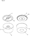
- figure 1 shows parts of a housing of a filter capsule according to the invention. At the edge of the bottom 1 of the housing there extends a side wall 2 which in this case has a cylinder-like shape.
- the cover 3 is attached reversibly or irreversibly to the side wall 2 .
- the cover has at least one fluid channel 12 .
- FIG. 2 shows different views of a filter capsule according to the invention.
- the base 1 is monolithically connected to the side wall 2 and the side wall 2 is irreversibly connected to the cover 3.
- the filter element 4 is arranged in the housing formed from the base 1, side wall 2 and cover 3.
- a circular elevation 5 on the bottom 1 and a circular elevation 33 on the cover 3 prevent liquid in the filter capsule from being able to flow past the filter element 4 .
- the base 1 has an indentation 6 which has a bulge 7 in the direction of the filter element 4 and a base groove 8 .
- a fluid channel 17 of the filter capsule, which extends along the side wall 2, is also shown.
- This filter capsule also contains a catch screen 18 to catch macroscopic particles and fibers of the filter element 4 and hold them back.
- the filter capsule has a predetermined breaking point 13 in the cover (here: a membrane), which breaks in the event of excess pressure. Liquid can thus flow past the filter element 4 directly from the inlet to the outlet of the filter capsule ("bypass"). Consequently, a possible destruction of the filter capsule due to excess pressure can be avoided.
- FIG. 3 shows further different views of a filter capsule according to the invention.
- the base 1 is also here monolithically connected to the side wall 2 and the side wall 2 is irreversibly connected to the cover 3 .
- the filter element 4 is arranged in the housing formed from the base 1, side wall 2 and cover 3.
- a circular elevation 5 on the bottom 1 and a circular elevation 33 on the cover 3 prevent liquid in the filter capsule from being able to flow past the filter element 4 .
- the base 1 has an indentation 6 which has a bulge 7 in the direction of the filter element 4 and a base groove 8 .
- a fluid channel 12 located in the cover 3 is also shown.
- a fluid channel 17 of the filter capsule, which extends along the side wall 2, is also shown.
- the arrangement is one Lateral surface groove 32 of the indentation 6 of the bottom 1 of the housing highlighted, which facilitates the connection of an adapter capsule to the filter capsule.
- This filter capsule also contains a predetermined breaking point 13 in the cover (here: a membrane), which breaks in the event of excess pressure and does not allow liquid to pass through the filter element 4, but instead short-circuits the inlet and outlet ("bypass"). Consequently, a possible destruction of the filter capsule due to excess pressure can be avoided.
- FIG 4 shows a cross section of a filter capsule according to the invention.
- the base 1 is also here monolithically connected to the side wall 2 and the side wall 2 is irreversibly connected to the cover 3 .
- the filter element 4 is arranged in the housing formed from the base 1, side wall 2 and cover 3.
- a circular elevation 5 on the bottom 1 and a circular elevation 33 on the cover 3 prevent liquid in the filter capsule from being able to flow past the filter element 4 .
- the base 1 has an indentation 6 which has a bulge 7 in the direction of the filter element 4 and a base groove 8 .
- a fluid channel 17 of the filter capsule, which extends along the side wall 2, is also shown.
- a side surface groove 32 of the indentation 6 of the base 1 of the housing is emphasized, which facilitates the connection of an adapter capsule to the filter capsule.
- a strainer 18 to catch and hold back macroscopic particles and fibers of the filter element 4 and a sealing surface 30 located in the cover 3 for the supply of liquid and a sealing surface 31 located in the cover 3 for the drainage of liquid.
- the base 1 here has a base area 1' which is elastic (elastic material or small thickness). This has the advantage that in the event of excess pressure in the filter capsule, liquid is not retained by the sealing of the circular elevation 5 on the bottom 1 of the housing. Rather, under these conditions, liquid can flow past the filter element 4 ("bypass") and pressure-related damage to the filter capsule can be avoided.
- FIG. 5 shows schematically the structure of a filter element according to the invention.
- the base 1 is also here monolithic with the side wall 2.
- a filter element 4 is inserted in the monolithic piece of base 1 and side wall 2.
- a strainer 18 is placed on the filter element 4 to catch and hold back macroscopic particles and fibers of the filter element 4 during operation of the filter capsule.
- a fluid channel disk 14 is placed on the catch screen 18 and has a continuous recess 15 in its center and contains at least one fluid channel 16 .
- the cover 3 is placed on this fluid channel disk 14 and can be reversibly or irreversibly connected to the side wall 2 in order to close the housing.
- the cover 3 has a fluid inlet 9 and a fluid outlet 10, which can optionally be closed using a sealing film 34 in order to increase the long-term stability of the filter capsule during storage.
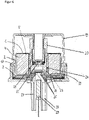
- FIG 6 shows a cross section of a filter capsule according to the invention, which is inserted into an adapter capsule 19 .
- the bottom 1 of the filter capsule is monolithically connected to the side wall 2 and the side wall 2 is irreversibly connected to the cover 3.
- the filter element 4 is arranged in the housing formed from the base 1, side wall 2 and cover 3.
- a circular elevation 5 on the bottom 1 and a circular elevation 33 on the cover 3 prevent liquid in the filter capsule from being able to flow past the filter element 4 .
- a fixing element 20 of the adapter capsule 19 is arranged in an indentation on the bottom 1 of the filter capsule, with the fixing element 20 being positively connected to the filter capsule via a side surface bulge 24 of the adapter capsule 19 in a side surface groove of the indentation on the bottom 1 of the filter capsule.
- a spring element 21 of the adapter capsule 19 exerts spring pressure on the filter capsule and presses it against an inlet 27 and an outlet 28 of a coffee machine.
- a sealing ring 25 and a silicone seal 26 of the adapter capsule 19 ensure that no liquid runs past the filter capsule.
- the adapter capsule 19 also has a magnet 22 with which it can be detected whether a filter capsule is inserted into the adapter capsule 19 or not. The detection can take place, for example, via a sensor 29 of the coffee machine.
Landscapes
- Engineering & Computer Science (AREA)
- Food Science & Technology (AREA)
- Chemical & Material Sciences (AREA)
- Life Sciences & Earth Sciences (AREA)
- Polymers & Plastics (AREA)
- Chemical Kinetics & Catalysis (AREA)
- Water Supply & Treatment (AREA)
- Mechanical Engineering (AREA)
- Apparatus For Making Beverages (AREA)
Claims (15)
- Capsule filtrante pour la post-filtration de café extrait, dans laquelle la capsule filtrante contient un boîtier et au moins un élément filtrant (4) ou en est constituée, dans laquelle le boîtier contient un fond (1, 1'), au moins une paroi latérale (2) et au moins un couvercle (3) ou en est constitué et l'au moins un élément filtrant (4) est disposé dans un espace intérieur du boîtier, caractérisée en ce quele couvercle (3) présente au moins une entrée de fluide (9) continue, qui est disposée de manière adjacente à un axe central d'une surface de base du couvercle (3), etle couvercle (3) présente au moins une sortie de fluide (10) continue.
- Capsule filtrante selon la revendication 1, caractérisée en ce que l'élément filtrant (4)i) contient au moins un filtre, qui présente une taille de pores maximale de 80 µm et présente de préférence une épaisseur de 0,1 mm à 10 mm ; et/ouii) contient au moins un filtre fin, qui présente de préférence une taille de pores maximale de 25 µm et de manière particulièrement préférée une épaisseur de 0,1 mm à 10 mm ; et/ouiii) contient au moins un filtre ultrafin, qui présente de préférence une taille de pores maximale de 10 µm et de manière particulièrement préférée une épaisseur de 0,1 mm à 10 mm ;ou en est constitué, dans laquelle l'élément filtrant (4) contient de préférence au moins un filtre, au moins un filtre fin et au moins un filtre ultrafin ou en est constitué et de manière particulièrement préférée l'au moins un filtre fin est disposé en aval du filtre et l'au moins un filtre ultrafin est disposé en aval du filtre fin.
- Capsule filtrante selon l'une quelconque des revendications précédentes, caractérisée en ce que l'élément filtrant (4)i) présente une longueur, une largeur et/ou un diamètre dans la plage de 1 à 10 cm, de préférence 2 à 9 cm, de manière particulièrement préférée 3 à 8 cm, mieux encore 4 à 7 cm, en particulier 5 à 6 cm ; et/ouii) présente une hauteur dans une plage de 1 à 14 cm, de préférence 2 à 12 cm, de manière particulièrement préférée 3 à 10 cm, mieux encore 4 à 8 cm, en particulier de 5 à 6 cm.
- Capsule filtrante selon l'une quelconque des revendications précédentes, caractérisée en ce que l'élément filtrant (4), de préférence au moins un filtre, filtre fin et/ou filtre ultrafin de l'élément filtrant (4), contienti) du papier ; et/ouii) du plastique ; et/ouiii) du métal ;ou en est constitué.
- Capsule filtrante selon l'une quelconque des revendications précédentes, caractérisée en ce que l'élément filtrant (4), de préférence au moins un filtre, filtre fin et/ou filtre ultrafin de l'élément filtrant (4), est configuré sensiblement sous la forme d'un cylindre droit ou incliné, éventuellement avec un évidement cylindrique droit ou incliné au centre du cylindre, dans laquelle le cylindre présente de préférence une surface de base, éventuellement pourvue d'un trou au centre, qui est choisie dans le groupe constitué par une surface de base circulaire, une surface de base semi-circulaire, une surface de base en forme de croissant, une surface de base elliptique et une surface de base avec au moins deux coins, dans laquelle une surface de base circulaire est particulièrement préférée.
- Capsule filtrante selon l'une quelconque des revendications précédentes, caractérisée en ce que l'élément filtrant (4), de préférence au moins un filtre, filtre fin et/ou filtre ultrafin de l'élément filtrant (4), peut être traversé par un fluide, de préférence une solution aqueuse, de préférence encore du café,i) radialement, de préférence peut être traversé radialement en direction d'un axe du cylindre par un fluide venant de l'amont et/ou peut être traversé radialement dans une direction s'écartant d'un axe du cylindre par un fluide venant de l'aval ; et/ouii) peut être traversé axialement, de préférence par un fluide venant de l'amont dans une direction le long d'un axe du cylindre depuis un côté supérieur de l'élément filtrant (4) vers un côté inférieur de l'élément filtrant (4) et/ou peut être traversé par un fluide venant de l'aval dans une direction le long d'un axe du cylindre depuis un côté inférieur de l'élément filtrant (4) vers un côté supérieur de l'élément filtrant (4).
- Capsule filtrante selon l'une quelconque des revendications précédentes, caractérisée en ce que le fond (1, 1')i) présente une surface de base avec une longueur, une largeur et/ou un diamètre qui est plus grand(e) que la longueur, la largeur et/ou le diamètre de la surface de base de l'élément filtrant (4), de préférence de 0,01 à 5 mm, de manière particulièrement préférée de 0,05 à 4 mm, mieux encore de 0,1 à 3 mm, en particulier de 0,2 à 2 mm, plus grand(e), dans laquelle éventuellement la longueur, la largeur et/ou le diamètre du couvercle (3) est plus grand(e) que celui(celle) du fond (1, 1') ; et/ouii) présente sur un côté tourné vers le au moins un élément filtrant (4) au moins une élévation, de préférence au moins une élévation circulaire (5), qui s'étend en direction de l'élément filtrant (4), de préférence s'étend en direction d'un filtre ultrafin de l'élément filtrant (4), et ferme l'espace entre le fond (1, 1') et l'élément filtrant (4) de manière étanche aux liquides ; et/ouiii) présente une épaisseur dans la plage de 0,1 à 2 mm, de préférence de 0,2 à 1,5 mm, de manière particulièrement préférée de 0,3 à 1,0 mm, en particulier de 0,4 à 0,5 mm ; et/ouiv) contient une zone élastique ou en est constituée, de préférence une zone élastique dont l'élasticité est provoquée par une certaine épaisseur, une certaine géométrie et/ou un certain matériau.
- Capsule filtrante selon l'une quelconque des revendications précédentes, caractérisée en ce que le fond (1, 1') présente un renfoncement (6) qui s'étend en direction du couvercle (3), de préférence sur au moins 25 % de la hauteur de la au moins une paroi latérale (2), de manière particulièrement préférée au moins 50 % de la hauteur de la au moins une paroi latérale (2), mieux encore au moins 75 % de la hauteur de la au moins une paroi latérale (2), en particulier au moins 90 % de la hauteur de la au moins une paroi latérale (2), dans laquelle le renfoncement (6) de préférencei) est disposé dans un évidement cylindrique de l'élément filtrant (4) ; et/ouii) contient au moins une nervure s'étendant en direction de la au moins une paroi latérale (2), de préférence au moins deux nervures s'étendant en direction de la au moins une paroi latérale (2), de manière particulièrement préférée au moins quatre nervures s'étendant en direction de la au moins une paroi latérale (2), mieux encore respectivement deux nervures sont disposées à l'opposé l'une de l'autre et les nervures s'étendent en particulier le long du renfoncement (6) du fond (1, 1') en direction du couvercle (3), éventuellement sur une longueur qui atteint au moins 50 % de la longueur de la au moins une paroi latérale (2) ; et/ouiii) contient une rainure de surface de base (8), qui est de préférence disposée dans une surface de base du renfoncement (6) disposée parallèlement au couvercle (3), de manière particulièrement préférée est disposée de manière concentrique autour d'un axe central d'une surface de base du couvercle (3) ; et/ouiv) contient une rainure de surface latérale (32), qui est de préférence disposée dans une surface latérale du renfoncement (6) disposée sensiblement perpendiculairement au couvercle (3), de manière particulièrement préférée est disposée de manière concentrique autour d'un axe central d'une surface de base du couvercle (3).
- Capsule filtrante selon l'une quelconque des revendications précédentes, caractérisée en ce que la au moins une paroi latérale (2)i) présente une hauteur qui est plus grande que la hauteur de l'élément filtrant (4) de préférence de 0,01 à 5 mm, de manière particulièrement préférée de 0,05 à 4 mm, mieux encore de 0,1 à 3 mm, en particulier de 0,2 à 2 mm, plus grande ; et/ouii) est reliée de manière réversible au couvercle (3), de préférence par l'intermédiaire d'une liaison par complémentarité de formes et/ou à force, de manière particulièrement préférée par l'intermédiaire d'une liaison par vissage ou liaison par serrage, ou est reliée de manière irréversible au couvercle (3), de préférence par l'intermédiaire d'une liaison de matière, de manière particulièrement préférée par l'intermédiaire d'une liaison soudée ou liaison adhésive ; et/ouiii) présente une épaisseur dans la plage de 0,1 à 2 mm, de préférence de 0,2 à 1,5 mm, de manière particulièrement préférée de 0,3 à 1,0 mm, en particulier de 0,4 à 0,5 mm ; et/ouiv) contient au moins une nervure s'étendant en direction de l'élément filtrant (4), de préférence au moins deux nervures s'étendant en direction de l'élément filtrant (4), de manière particulièrement préférée au moins quatre nervures s'étendant en direction de l'élément filtrant (4), mieux encore respectivement deux nervures sont disposées à l'opposé l'une de l'autre et les nervures s'étendent en particulier le long de la au moins une paroi latérale (2) en direction du couvercle (3), éventuellement sur une longueur qui atteint au moins 50 % de la longueur de la au moins une paroi latérale (2) ; et/ouv) contient une zone élastique ou en est constituée, de préférence une zone élastique dont l'élasticité est provoquée par une certaine épaisseur, une certaine géométrie et/ou un certain matériau.
- Capsule filtrante selon l'une quelconque des revendications précédentes, caractérisée en ce que le couvercle (3)i) présente une surface de base avec une longueur, une largeur et/ou un diamètre qui est plus grand(e) que la longueur, la largeur et/ou le diamètre de la surface de base de l'élément filtrant (4), de préférence de 0,01 à 5 mm, de manière particulièrement préférée de 0,05 à 4 mm, mieux encore de 0,1 à 3 mm, en particulier de 0,2 à 2 mm, plus grand(e), dans laquelle éventuellement la longueur, la largeur et/ou le diamètre du couvercle (3) est plus grand(e) que celui(celle) du fond (1, 1') ; et/ouii) la au moins une entrée de fluide (9), qui est disposée de manière adjacente à un axe central d'une surface de base du couvercle (3), contient une membrane pour éviter que le liquide ne s'égoutte de la capsule filtrante ; et/ouiii) la au moins une sortie de fluide (10), qui est disposée le long d'un axe central d'une surface de base du couvercle (3), contient de manière particulièrement préférée une membrane pour éviter que le liquide ne s'égoutte de la capsule filtrante ; et/ouiv) présente sur un côté opposé à l'au moins un élément filtrant (4) au moins une, de préférence au moins deux, de manière particulièrement préférée au moins quatre, en particulier au moins huit éléments d'écartement (11), qui sont éventuellement monolithiques avec le couvercle (3) ; et/ouv) présente sur un côté tourné vers l'au moins un élément filtrant (4) au moins un, de préférence au moins deux, de manière particulièrement préférée au moins trois, en particulier au moins quatre canaux de fluide (12), qui s'étendent de préférence depuis un centre d'une surface de base du couvercle (3) en direction d'au moins une paroi latérale (2) de la capsule filtrante et de manière particulièrement préférée sont fermés vers un côté de l'élément filtrant (4) tourné vers le couvercle (3), éventuellement par l'intermédiaire d'un disque de canal de fluide (14) ; et/ouvi) présente un point de rupture (13), de préférence une membrane, qui est adaptée pour dévier le flux de fluide dans la capsule filtrante devant l'élément filtrant (4) en cas de surpression ; et/ouvii) présente une feuille d'étanchéité (34), qui ferme de manière étanche aux fluides une entrée de fluide (9) et/ou sortie de fluide (10) du couvercle (3) ; et/ouviii) présente sur un côté tourné vers l'au moins un élément filtrant (4) au moins une élévation, de préférence au moins une élévation circulaire (33), qui s'étend en direction de l'élément filtrant (4), de préférence s'étend en direction d'un filtre ultrafin de l'élément filtrant (4), et ferme l'espace entre le couvercle (3) et l'élément filtrant (4) de manière étanche aux liquides.
- Capsule filtrante selon l'une quelconque des revendications précédentes, caractérisée en ce que la capsule filtrante contient un disque de canal de fluide (14), qui est disposé entre le couvercle (3) et un côté de l'élément filtrant (4) tourné vers le couvercle (3), dans laquelle le disque de canal de fluide (14) de préférencei) présente un évidement traversant (15), dans laquelle l'évidement traversant (15) est de préférence disposé sensiblement au centre d'une surface de base du disque de canal de fluide (14) ; et/ouii) présente sur un côté tourné vers l'au moins un élément filtrant (4) au moins un, de préférence au moins deux, de manière particulièrement préférée au moins trois, en particulier au moins quatre canaux de fluide (16), qui s'étendent de préférence depuis un centre d'une surface de base du disque de canal de fluide (14) en direction d'au moins une paroi latérale (2) de la capsule de filtre et de manière particulièrement préférée sont fermés vers un côté de l'élément filtrant (4) tourné vers le couvercle (3), éventuellement par l'intermédiaire d'un disque de canal de fluide (14) ; et/ouiii) présente sur un côté tourné vers le au moins un élément filtrant (4) au moins une élévation, de préférence au moins une élévation circulaire, qui s'étend en direction de l'élément filtrant (4), de préférence s'étend en direction d'un filtre ultrafin de l'élément filtrant (4), et ferme de manière étanche aux liquides l'espace entre le disque de canal de fluide (14) et l'élément filtrant (4) ; et/ouiv) présente un point de rupture (13), de préférence une membrane, qui est adaptée pour dévier le flux de fluide dans la capsule filtrante devant l'élément filtrant (4) en cas de surpression ; et/ouv) est disposé parallèlement à une surface de base du couvercle (3).
- Capsule filtrante selon l'une quelconque des revendications précédentes, caractérisée en ce que la capsule filtrante contient au moins une conduite de fluide (17), qui entre dans la capsule filtrante à travers le couvercle (3) dans une zone adjacente à un axe central à travers une surface de base du couvercle (3), s'étend sur un côté du couvercle (3) tourné vers l'élément filtrant (4) en direction de la au moins une paroi latérale (2), s'étend de préférence le long de la au moins une paroi latérale (2), s'étend de manière particulièrement préférée à travers le au moins un élément filtrant (4), s'étend mieux encore dans une zone au centre de la capsule filtrante et sort de la capsule filtrante à travers le couvercle (3) en particulier le long de l'axe central à travers la surface de base du couvercle (3).
- Capsule filtrante selon l'une quelconque des revendications précédentes, caractérisée en ce que la capsule filtrante contient un tamis de capture (18), qui est disposé en aval de l'au moins un élément filtrant, est de préférence intégré dans le couvercle (3) ou est disposé entre l'élément filtrant (4) et le couvercle (3), et de manière particulièrement préférée présente une taille de pores dans la plage de 50 à 500 µm, mieux encore présente une épaisseur de 0,1 mm à 10 mm et en particulier est disposé parallèlement à une surface de base du couvercle (3).
- Capsule filtrante selon l'une quelconque des revendications précédentes, caractérisée en ce que la capsule filtrante est reliée à une capsule d'adaptation (19), dans laquelle la capsule d'adaptation (19) de préférencei) est adaptée pour être reliée à un support d'une machine à café, de préférence par l'intermédiaire d'une liaison réversible, de manière particulièrement préférée par l'intermédiaire d'une fermeture à vis, fermeture à clapet et/ou fermeture à baïonnette ; et/ouii) contient au moins un aimant (22), dans laquelle le au moins un aimant (22) est de préférence adapté pour détecter si la capsule d'adaptation (19) est reliée à une capsule filtrante ; et/ouiii) contient au moins un élément de fixation (20) monté par l'intermédiaire d'un élément ressort (21), dans laquelle l'élément de fixation (20) est de préférence approprié pour presser la capsule filtrante contre un support d'une machine à café, en particulier par l'exercice d'une pression sur un renfoncement (6) dans le fond (1, 1') du boîtier de l'élément filtrant (4) et de manière particulièrement préférée est adapté pour établir une liaison fluidique entre une arrivée (27) et une évacuation (28) de la machine à café en l'absence d'une capsule filtrante ; et/ouiv) contient au moins un renflement de surface de base (23), qui est de préférence adapté pour s'encliqueter dans une rainure de surface de base (8) d'un renfoncement (6) du fond (1, 1') du boîtier ; et/ouv) contient au moins un renflement de surface latérale (24), qui est de préférence adapté pour s'encliqueter dans une rainure de surface latérale (32) d'un renfoncement (6) du fond (1, 1') du boîtier.
- Utilisation de la capsule filtrante selon l'une quelconque des revendications précédentes pour la post-filtration de café.
Applications Claiming Priority (2)
| Application Number | Priority Date | Filing Date | Title |
|---|---|---|---|
| DE102017202685.5A DE102017202685A1 (de) | 2017-02-20 | 2017-02-20 | Filterkapsel zur Nachfiltration von Kaffee und Verwendung hiervon |
| PCT/EP2018/053765 WO2018149911A1 (fr) | 2017-02-20 | 2018-02-15 | Capsule filtrante pour la post-filtration de café et utilisation de ladite capsule |
Publications (2)
| Publication Number | Publication Date |
|---|---|
| EP3496579A1 EP3496579A1 (fr) | 2019-06-19 |
| EP3496579B1 true EP3496579B1 (fr) | 2022-08-03 |
Family
ID=61256936
Family Applications (1)
| Application Number | Title | Priority Date | Filing Date |
|---|---|---|---|
| EP18706466.2A Active EP3496579B1 (fr) | 2017-02-20 | 2018-02-15 | Capsule filtrante pour la post-filtration de café et utilisation de ladite capsule |
Country Status (8)
| Country | Link |
|---|---|
| US (1) | US11617468B2 (fr) |
| EP (1) | EP3496579B1 (fr) |
| JP (1) | JP7104467B2 (fr) |
| KR (1) | KR102397671B1 (fr) |
| CN (1) | CN110300535A (fr) |
| DE (1) | DE102017202685A1 (fr) |
| TW (1) | TWI733983B (fr) |
| WO (1) | WO2018149911A1 (fr) |
Families Citing this family (2)
| Publication number | Priority date | Publication date | Assignee | Title |
|---|---|---|---|---|
| TWI714360B (zh) * | 2019-11-21 | 2020-12-21 | 錢文正 | 濾杯結構 |
| US20240382035A1 (en) * | 2020-06-19 | 2024-11-21 | Carimali S.P.A. | Coffee machine with automatic locking of the filter-holder |
Family Cites Families (48)
| Publication number | Priority date | Publication date | Assignee | Title |
|---|---|---|---|---|
| US2626558A (en) | 1949-01-07 | 1953-01-27 | Jacob R Stein | Method of preparing coffee |
| US2997178A (en) * | 1959-04-13 | 1961-08-22 | Lorimer William | Water filter |
| DE6607066U (de) | 1965-07-14 | 1971-01-14 | Siemens Elektrogeraete Gmbh | Filter zur zubereitung von bruehgetraenken |
| DE6939904U (de) | 1969-10-13 | 1970-03-05 | Vox Kaffee Werk Groneweg & Mei | Filtertuete zum aufbereiten eines kaffeegetraenkes |
| US3773180A (en) * | 1972-04-10 | 1973-11-20 | D Harrison | Oil filter housing assembly |
| CH562852A5 (en) * | 1972-08-15 | 1975-06-13 | Basf Ag | Perylene tetracarboxylic diimide dyes - contg n-substd pyrazole groups,for mass-colouring of plastics |
| CH561644A5 (fr) * | 1972-08-15 | 1975-05-15 | Battelle Memorial Institute | |
| DE3200440A1 (de) | 1982-01-09 | 1983-07-21 | Licentia Patent-Verwaltungs-Gmbh, 6000 Frankfurt | Dauerverwendbarer trichterfoermiger kaffeefilter |
| JPS60106551U (ja) * | 1983-12-26 | 1985-07-20 | 株式会社東芝 | コ−ヒ−ミル |
| US4735716A (en) * | 1986-01-27 | 1988-04-05 | Cuno Corporated | Quick-change filter cartridge and head therefor |
| JPS62211799A (ja) * | 1986-03-12 | 1987-09-17 | 株式会社クボタ | 自動販売機の抽出濾過装置 |
| US4642183A (en) * | 1986-03-21 | 1987-02-10 | Hebert Alfred M | Oil filter |
| DE10022538C2 (de) | 2000-05-09 | 2002-05-29 | Wmf Wuerttemberg Metallwaren | Verfahren und Vorrichtung zum Abscheiden von Getränkesatz |
| US7087166B1 (en) * | 2001-10-01 | 2006-08-08 | Entegris, Inc. | Filter element and filter device having replaceable filter |
| US6786134B2 (en) | 2002-02-07 | 2004-09-07 | The Coca-Cola Company | Coffee and tea dispenser |
| NL1020755C2 (nl) | 2002-05-31 | 2003-12-02 | Antonius Klaassen | Filter voor extractie inrichting. |
| JP4339358B2 (ja) | 2003-05-27 | 2009-10-07 | コーニンクレッカ フィリップス エレクトロニクス エヌ ヴィ | ブリュー容器並びにこのようなブリュー容器を有するフォームユニット及び飲料メーカー |
| US7717026B1 (en) | 2003-05-28 | 2010-05-18 | Food Equipment Technologies Company, Inc. | Multicontrolled brewer for optimum flavor extraction |
| US20080038441A1 (en) | 2003-07-22 | 2008-02-14 | The Coca-Cola Company | Systems and Methods of Brewing Low-Cholesterol Espresso |
| DE102004002005A1 (de) | 2004-01-14 | 2005-08-11 | Schifferle, René | Portionskapsel mit gemahlenem Kaffee zur Herstellung eines Kaffeegetränks |
| US7089849B2 (en) | 2004-05-06 | 2006-08-15 | Electrical And Electronics Limited | Single/multiple beverage machine |
| AU2005240216B2 (en) | 2004-05-06 | 2011-01-20 | Electrical And Electronics Limited | Single/multiple beverage machine |
| CN2732112Y (zh) | 2004-09-23 | 2005-10-12 | 何庭华 | 一体式蒸气压力咖啡壶 |
| JP2005187076A (ja) | 2005-01-17 | 2005-07-14 | Hoshizaki Electric Co Ltd | 水利用装置 |
| DK1767467T3 (da) | 2005-09-21 | 2009-08-10 | Illycaffe Spa | Indsats indeholdende et stof til ekstrahering af en drik |
| JP4990578B2 (ja) | 2006-08-01 | 2012-08-01 | キリンビバレッジ株式会社 | 茶殻分離液の製造方法 |
| ITMI20070740A1 (it) | 2007-04-12 | 2008-10-13 | Rossi Corp S R L | Capsula monouso di contenimento di un essenza aromatica per la produzione di un infuso |
| WO2011030340A2 (fr) | 2009-09-09 | 2011-03-17 | Strauss Water Ltd | Dispositif de filtration de liquide |
| DE102010004729B4 (de) | 2010-01-14 | 2017-04-27 | Wmf Group Gmbh | Vorrichtung nach dem Steigrohrprinzip für die Zubereitung eines Heißgetränks, insbesondere Espressokanne |
| CN101862120A (zh) * | 2010-02-11 | 2010-10-20 | 广东新宝电器股份有限公司 | 一种压力咖啡机的过滤装置 |
| DE102010012788B4 (de) | 2010-03-16 | 2018-05-17 | Wmf Group Gmbh | Espressomaschine oder Kaffeevollautomat mit automatischer Homogenisierung |
| EP2401945A1 (fr) | 2010-07-01 | 2012-01-04 | Nestec S.A. | Dispositif d'adaptation d'une capsule d'aliments dans un support de capsule |
| DE102010048517A1 (de) | 2010-10-14 | 2012-04-19 | Yafes Tandir | Wieder Verwendbare Filterkapsel |
| ITBO20110101A1 (it) | 2011-03-02 | 2012-09-03 | Macchiavelli Srl | Capsula intercambiabile per la preparazione di una infusione di caffe', e procedimento per l'ottenimento di una infusione di tale caffe' |
| GB201112058D0 (en) | 2011-07-13 | 2011-08-31 | Mars Inc | Beverage preparation capsules |
| DK2742122T3 (en) | 2011-08-12 | 2018-02-26 | Univ Denmark Tech Dtu | Filtering apparatus and process for mixing, extracting and / or separating |
| CN202714726U (zh) | 2012-06-14 | 2013-02-06 | 漳州灿坤实业有限公司 | 一种可拆装的咖啡机过滤机构 |
| DE202012007498U1 (de) | 2012-08-03 | 2012-08-29 | Rebecca Filter Gmbh | Kalkschutzgranulat integriert in einem zylindrischen Filter |
| CN202918964U (zh) | 2012-11-13 | 2013-05-08 | 苏州凯新分离科技有限公司 | 一种咖啡液膜浓缩装置 |
| ITPD20130051A1 (it) * | 2013-03-01 | 2014-09-02 | Laica Spa | Filtro e serbatoio per macchina per la preparazione di bevande calde |
| DE102013011746A1 (de) | 2013-07-13 | 2015-01-15 | Manfred Völker | Chlormessung/Filterprüfung/Solebehälterüberwachung einer Wasseraufbereitungsanlage |
| CN104679042A (zh) | 2013-12-03 | 2015-06-03 | 常州新江南能源设备有限公司 | 反渗透压力可调式爆破装置 |
| ITBO20130702A1 (it) | 2013-12-20 | 2015-06-21 | Macchiavelli Srl | Capsula intercambiabile per la preparazione di una infusione di un prodotto in polvere e relativo procedimento per l'ottenimento di una tale infusione |
| KR102136337B1 (ko) | 2013-12-30 | 2020-07-22 | 코웨이 주식회사 | 음료추출장치 및 음료추출방법 |
| AU2015275748B2 (en) | 2014-06-18 | 2019-05-16 | Luigi Lavazza S.P.A. | Cartridge for preparing a liquid product and method for producing it |
| US10399006B2 (en) | 2015-03-17 | 2019-09-03 | California Extraction Ventures, Inc. | Catalyzing pressure wave extraction method and apparatus |
| CN104840103A (zh) | 2015-04-28 | 2015-08-19 | 周林斌 | 一种磨豆咖啡壶的流水装置 |
| DE102016212988A1 (de) | 2016-07-15 | 2018-01-18 | Wmf Group Gmbh | Kaffeemaschine zur Zubereitung von druckextrahierten Kaffee mit geringem Partikelgehalt, Verfahren hierzu und Verwendung der Kaffeemaschine |
-
2017
- 2017-02-20 DE DE102017202685.5A patent/DE102017202685A1/de not_active Withdrawn
-
2018
- 2018-02-09 TW TW107104683A patent/TWI733983B/zh active
- 2018-02-15 EP EP18706466.2A patent/EP3496579B1/fr active Active
- 2018-02-15 CN CN201880012751.1A patent/CN110300535A/zh active Pending
- 2018-02-15 WO PCT/EP2018/053765 patent/WO2018149911A1/fr not_active Ceased
- 2018-02-15 US US16/486,890 patent/US11617468B2/en active Active
- 2018-02-15 KR KR1020197023874A patent/KR102397671B1/ko active Active
- 2018-02-15 JP JP2019544903A patent/JP7104467B2/ja active Active
Also Published As
| Publication number | Publication date |
|---|---|
| TW201840289A (zh) | 2018-11-16 |
| US20200229632A1 (en) | 2020-07-23 |
| JP2020508137A (ja) | 2020-03-19 |
| EP3496579A1 (fr) | 2019-06-19 |
| US11617468B2 (en) | 2023-04-04 |
| DE102017202685A1 (de) | 2018-08-23 |
| KR20190121302A (ko) | 2019-10-25 |
| WO2018149911A1 (fr) | 2018-08-23 |
| JP7104467B2 (ja) | 2022-07-21 |
| CN110300535A (zh) | 2019-10-01 |
| KR102397671B1 (ko) | 2022-05-16 |
| TWI733983B (zh) | 2021-07-21 |
Similar Documents
| Publication | Publication Date | Title |
|---|---|---|
| DE69502802T2 (de) | Filtriereinrichtung mit niedrigem restvolumen | |
| EP1944248B1 (fr) | Capsule, moyen de pénétration du fond d'une capsule et dispositif de préparation d'une boisson | |
| EP3271043B1 (fr) | Dispositif filtrant | |
| DE60220407T2 (de) | Aufschraubbarer hybridfilter | |
| WO2022263250A2 (fr) | Filtre à microplastique pour lave-linge | |
| EP3383232B1 (fr) | Machine à café pour la préparation de café extrait sous pression avec une faible teneur en particules, procédé associé et utilisation de la machine à café | |
| DE102008012521A1 (de) | Filtervorrichtung sowie Filterelement für eine dahingehende Filtervorrichtung | |
| DE102011005106A1 (de) | Umgehungsventil, Einrichtung mit Umgehungsventil und Filtereinsatz der Einrichtung | |
| EP2448647A1 (fr) | Dispositif de filtration et agencement d'élément filtrant destiné à être utilisé dans le dispositif de filtration | |
| EP3496579B1 (fr) | Capsule filtrante pour la post-filtration de café et utilisation de ladite capsule | |
| DE102021002428A1 (de) | Filtervorrichtung | |
| DE102008027250B4 (de) | Gehäuse zur Filtration | |
| EP2187789B1 (fr) | Système comprenant une machine d'infusion et un support de doses | |
| DE10113179A1 (de) | Filter | |
| DE3000013C2 (fr) | ||
| EP3684494B1 (fr) | Dispositif de filtration | |
| EP3144053B1 (fr) | Récipient pour une cartouche filtrante et ensemble de filtre | |
| EP2956385B1 (fr) | Capsule | |
| EP1419807B1 (fr) | Dispositif de filtration avec cartouche filtrante remplaçable | |
| EP3967662A1 (fr) | Cartouche filtrante et dispositif filtrant | |
| DE202006004529U1 (de) | Filtereinsatz mit Verschluss für zweite Filterkammer | |
| DE3700999C2 (de) | Saugfilter für ein flüssiges Medium | |
| EP4115964B1 (fr) | Dispositif filtre | |
| EP3915447B1 (fr) | Dispositif de préparation de boissons chaudes doté d'un dispositif d'évacuation | |
| EP4458446A1 (fr) | Dispositif de filtration |
Legal Events
| Date | Code | Title | Description |
|---|---|---|---|
| STAA | Information on the status of an ep patent application or granted ep patent |
Free format text: STATUS: UNKNOWN |
|
| STAA | Information on the status of an ep patent application or granted ep patent |
Free format text: STATUS: THE INTERNATIONAL PUBLICATION HAS BEEN MADE |
|
| PUAI | Public reference made under article 153(3) epc to a published international application that has entered the european phase |
Free format text: ORIGINAL CODE: 0009012 |
|
| STAA | Information on the status of an ep patent application or granted ep patent |
Free format text: STATUS: REQUEST FOR EXAMINATION WAS MADE |
|
| 17P | Request for examination filed |
Effective date: 20190312 |
|
| AK | Designated contracting states |
Kind code of ref document: A1 Designated state(s): AL AT BE BG CH CY CZ DE DK EE ES FI FR GB GR HR HU IE IS IT LI LT LU LV MC MK MT NL NO PL PT RO RS SE SI SK SM TR |
|
| AX | Request for extension of the european patent |
Extension state: BA ME |
|
| RIN1 | Information on inventor provided before grant (corrected) |
Inventor name: OBERHANSL, DENIS Inventor name: STARTZ, ARMIN Inventor name: ARNDT, PETER Inventor name: SCHIRRMACHER, PHILIPP Inventor name: BAIS, JOHANNES |
|
| DAV | Request for validation of the european patent (deleted) | ||
| DAX | Request for extension of the european patent (deleted) | ||
| RAP3 | Party data changed (applicant data changed or rights of an application transferred) |
Owner name: WMF GMBH |
|
| GRAP | Despatch of communication of intention to grant a patent |
Free format text: ORIGINAL CODE: EPIDOSNIGR1 |
|
| STAA | Information on the status of an ep patent application or granted ep patent |
Free format text: STATUS: GRANT OF PATENT IS INTENDED |
|
| INTG | Intention to grant announced |
Effective date: 20220422 |
|
| GRAS | Grant fee paid |
Free format text: ORIGINAL CODE: EPIDOSNIGR3 |
|
| GRAA | (expected) grant |
Free format text: ORIGINAL CODE: 0009210 |
|
| STAA | Information on the status of an ep patent application or granted ep patent |
Free format text: STATUS: THE PATENT HAS BEEN GRANTED |
|
| AK | Designated contracting states |
Kind code of ref document: B1 Designated state(s): AL AT BE BG CH CY CZ DE DK EE ES FI FR GB GR HR HU IE IS IT LI LT LU LV MC MK MT NL NO PL PT RO RS SE SI SK SM TR |
|
| REG | Reference to a national code |
Ref country code: AT Ref legal event code: REF Ref document number: 1508067 Country of ref document: AT Kind code of ref document: T Effective date: 20220815 Ref country code: CH Ref legal event code: EP |
|
| REG | Reference to a national code |
Ref country code: DE Ref legal event code: R096 Ref document number: 502018010293 Country of ref document: DE |
|
| REG | Reference to a national code |
Ref country code: IE Ref legal event code: FG4D Free format text: LANGUAGE OF EP DOCUMENT: GERMAN Ref country code: NL Ref legal event code: FP |
|
| REG | Reference to a national code |
Ref country code: LT Ref legal event code: MG9D |
|
| PG25 | Lapsed in a contracting state [announced via postgrant information from national office to epo] |
Ref country code: SE Free format text: LAPSE BECAUSE OF FAILURE TO SUBMIT A TRANSLATION OF THE DESCRIPTION OR TO PAY THE FEE WITHIN THE PRESCRIBED TIME-LIMIT Effective date: 20220803 Ref country code: RS Free format text: LAPSE BECAUSE OF FAILURE TO SUBMIT A TRANSLATION OF THE DESCRIPTION OR TO PAY THE FEE WITHIN THE PRESCRIBED TIME-LIMIT Effective date: 20220803 Ref country code: PT Free format text: LAPSE BECAUSE OF FAILURE TO SUBMIT A TRANSLATION OF THE DESCRIPTION OR TO PAY THE FEE WITHIN THE PRESCRIBED TIME-LIMIT Effective date: 20221205 Ref country code: NO Free format text: LAPSE BECAUSE OF FAILURE TO SUBMIT A TRANSLATION OF THE DESCRIPTION OR TO PAY THE FEE WITHIN THE PRESCRIBED TIME-LIMIT Effective date: 20221103 Ref country code: LV Free format text: LAPSE BECAUSE OF FAILURE TO SUBMIT A TRANSLATION OF THE DESCRIPTION OR TO PAY THE FEE WITHIN THE PRESCRIBED TIME-LIMIT Effective date: 20220803 Ref country code: LT Free format text: LAPSE BECAUSE OF FAILURE TO SUBMIT A TRANSLATION OF THE DESCRIPTION OR TO PAY THE FEE WITHIN THE PRESCRIBED TIME-LIMIT Effective date: 20220803 Ref country code: FI Free format text: LAPSE BECAUSE OF FAILURE TO SUBMIT A TRANSLATION OF THE DESCRIPTION OR TO PAY THE FEE WITHIN THE PRESCRIBED TIME-LIMIT Effective date: 20220803 Ref country code: ES Free format text: LAPSE BECAUSE OF FAILURE TO SUBMIT A TRANSLATION OF THE DESCRIPTION OR TO PAY THE FEE WITHIN THE PRESCRIBED TIME-LIMIT Effective date: 20220803 |
|
| PG25 | Lapsed in a contracting state [announced via postgrant information from national office to epo] |
Ref country code: PL Free format text: LAPSE BECAUSE OF FAILURE TO SUBMIT A TRANSLATION OF THE DESCRIPTION OR TO PAY THE FEE WITHIN THE PRESCRIBED TIME-LIMIT Effective date: 20220803 Ref country code: IS Free format text: LAPSE BECAUSE OF FAILURE TO SUBMIT A TRANSLATION OF THE DESCRIPTION OR TO PAY THE FEE WITHIN THE PRESCRIBED TIME-LIMIT Effective date: 20221203 Ref country code: HR Free format text: LAPSE BECAUSE OF FAILURE TO SUBMIT A TRANSLATION OF THE DESCRIPTION OR TO PAY THE FEE WITHIN THE PRESCRIBED TIME-LIMIT Effective date: 20220803 Ref country code: GR Free format text: LAPSE BECAUSE OF FAILURE TO SUBMIT A TRANSLATION OF THE DESCRIPTION OR TO PAY THE FEE WITHIN THE PRESCRIBED TIME-LIMIT Effective date: 20221104 |
|
| PG25 | Lapsed in a contracting state [announced via postgrant information from national office to epo] |
Ref country code: SM Free format text: LAPSE BECAUSE OF FAILURE TO SUBMIT A TRANSLATION OF THE DESCRIPTION OR TO PAY THE FEE WITHIN THE PRESCRIBED TIME-LIMIT Effective date: 20220803 Ref country code: RO Free format text: LAPSE BECAUSE OF FAILURE TO SUBMIT A TRANSLATION OF THE DESCRIPTION OR TO PAY THE FEE WITHIN THE PRESCRIBED TIME-LIMIT Effective date: 20220803 Ref country code: DK Free format text: LAPSE BECAUSE OF FAILURE TO SUBMIT A TRANSLATION OF THE DESCRIPTION OR TO PAY THE FEE WITHIN THE PRESCRIBED TIME-LIMIT Effective date: 20220803 Ref country code: CZ Free format text: LAPSE BECAUSE OF FAILURE TO SUBMIT A TRANSLATION OF THE DESCRIPTION OR TO PAY THE FEE WITHIN THE PRESCRIBED TIME-LIMIT Effective date: 20220803 |
|
| REG | Reference to a national code |
Ref country code: DE Ref legal event code: R097 Ref document number: 502018010293 Country of ref document: DE |
|
| PG25 | Lapsed in a contracting state [announced via postgrant information from national office to epo] |
Ref country code: SK Free format text: LAPSE BECAUSE OF FAILURE TO SUBMIT A TRANSLATION OF THE DESCRIPTION OR TO PAY THE FEE WITHIN THE PRESCRIBED TIME-LIMIT Effective date: 20220803 Ref country code: EE Free format text: LAPSE BECAUSE OF FAILURE TO SUBMIT A TRANSLATION OF THE DESCRIPTION OR TO PAY THE FEE WITHIN THE PRESCRIBED TIME-LIMIT Effective date: 20220803 |
|
| PLBE | No opposition filed within time limit |
Free format text: ORIGINAL CODE: 0009261 |
|
| STAA | Information on the status of an ep patent application or granted ep patent |
Free format text: STATUS: NO OPPOSITION FILED WITHIN TIME LIMIT |
|
| PG25 | Lapsed in a contracting state [announced via postgrant information from national office to epo] |
Ref country code: AL Free format text: LAPSE BECAUSE OF FAILURE TO SUBMIT A TRANSLATION OF THE DESCRIPTION OR TO PAY THE FEE WITHIN THE PRESCRIBED TIME-LIMIT Effective date: 20220803 |
|
| P01 | Opt-out of the competence of the unified patent court (upc) registered |
Effective date: 20230525 |
|
| 26N | No opposition filed |
Effective date: 20230504 |
|
| PG25 | Lapsed in a contracting state [announced via postgrant information from national office to epo] |
Ref country code: SI Free format text: LAPSE BECAUSE OF FAILURE TO SUBMIT A TRANSLATION OF THE DESCRIPTION OR TO PAY THE FEE WITHIN THE PRESCRIBED TIME-LIMIT Effective date: 20220803 |
|
| PG25 | Lapsed in a contracting state [announced via postgrant information from national office to epo] |
Ref country code: MC Free format text: LAPSE BECAUSE OF FAILURE TO SUBMIT A TRANSLATION OF THE DESCRIPTION OR TO PAY THE FEE WITHIN THE PRESCRIBED TIME-LIMIT Effective date: 20220803 |
|
| REG | Reference to a national code |
Ref country code: BE Ref legal event code: MM Effective date: 20230228 |
|
| GBPC | Gb: european patent ceased through non-payment of renewal fee |
Effective date: 20230215 |
|
| PG25 | Lapsed in a contracting state [announced via postgrant information from national office to epo] |
Ref country code: LU Free format text: LAPSE BECAUSE OF NON-PAYMENT OF DUE FEES Effective date: 20230215 |
|
| REG | Reference to a national code |
Ref country code: IE Ref legal event code: MM4A |
|
| PG25 | Lapsed in a contracting state [announced via postgrant information from national office to epo] |
Ref country code: GB Free format text: LAPSE BECAUSE OF NON-PAYMENT OF DUE FEES Effective date: 20230215 |
|
| PG25 | Lapsed in a contracting state [announced via postgrant information from national office to epo] |
Ref country code: IE Free format text: LAPSE BECAUSE OF NON-PAYMENT OF DUE FEES Effective date: 20230215 Ref country code: GB Free format text: LAPSE BECAUSE OF NON-PAYMENT OF DUE FEES Effective date: 20230215 Ref country code: FR Free format text: LAPSE BECAUSE OF NON-PAYMENT OF DUE FEES Effective date: 20230228 |
|
| PG25 | Lapsed in a contracting state [announced via postgrant information from national office to epo] |
Ref country code: BE Free format text: LAPSE BECAUSE OF NON-PAYMENT OF DUE FEES Effective date: 20230228 |
|
| PGFP | Annual fee paid to national office [announced via postgrant information from national office to epo] |
Ref country code: NL Payment date: 20240129 Year of fee payment: 7 |
|
| PGFP | Annual fee paid to national office [announced via postgrant information from national office to epo] |
Ref country code: AT Payment date: 20240124 Year of fee payment: 7 |
|
| PG25 | Lapsed in a contracting state [announced via postgrant information from national office to epo] |
Ref country code: BG Free format text: LAPSE BECAUSE OF FAILURE TO SUBMIT A TRANSLATION OF THE DESCRIPTION OR TO PAY THE FEE WITHIN THE PRESCRIBED TIME-LIMIT Effective date: 20220803 |
|
| PG25 | Lapsed in a contracting state [announced via postgrant information from national office to epo] |
Ref country code: BG Free format text: LAPSE BECAUSE OF FAILURE TO SUBMIT A TRANSLATION OF THE DESCRIPTION OR TO PAY THE FEE WITHIN THE PRESCRIBED TIME-LIMIT Effective date: 20220803 |
|
| PG25 | Lapsed in a contracting state [announced via postgrant information from national office to epo] |
Ref country code: CY Free format text: LAPSE BECAUSE OF FAILURE TO SUBMIT A TRANSLATION OF THE DESCRIPTION OR TO PAY THE FEE WITHIN THE PRESCRIBED TIME-LIMIT; INVALID AB INITIO Effective date: 20180215 |
|
| PG25 | Lapsed in a contracting state [announced via postgrant information from national office to epo] |
Ref country code: HU Free format text: LAPSE BECAUSE OF FAILURE TO SUBMIT A TRANSLATION OF THE DESCRIPTION OR TO PAY THE FEE WITHIN THE PRESCRIBED TIME-LIMIT; INVALID AB INITIO Effective date: 20180215 |
|
| REG | Reference to a national code |
Ref country code: NL Ref legal event code: MM Effective date: 20250301 |
|
| REG | Reference to a national code |
Ref country code: AT Ref legal event code: MM01 Ref document number: 1508067 Country of ref document: AT Kind code of ref document: T Effective date: 20250215 |
|
| PG25 | Lapsed in a contracting state [announced via postgrant information from national office to epo] |
Ref country code: AT Free format text: LAPSE BECAUSE OF NON-PAYMENT OF DUE FEES Effective date: 20250215 |
|
| PG25 | Lapsed in a contracting state [announced via postgrant information from national office to epo] |
Ref country code: NL Free format text: LAPSE BECAUSE OF NON-PAYMENT OF DUE FEES Effective date: 20250301 |
|
| PG25 | Lapsed in a contracting state [announced via postgrant information from national office to epo] |
Ref country code: TR Free format text: LAPSE BECAUSE OF FAILURE TO SUBMIT A TRANSLATION OF THE DESCRIPTION OR TO PAY THE FEE WITHIN THE PRESCRIBED TIME-LIMIT Effective date: 20220803 |
|
| REG | Reference to a national code |
Ref country code: CH Ref legal event code: U11 Free format text: ST27 STATUS EVENT CODE: U-0-0-U10-U11 (AS PROVIDED BY THE NATIONAL OFFICE) Effective date: 20260301 |
|
| PGFP | Annual fee paid to national office [announced via postgrant information from national office to epo] |
Ref country code: DE Payment date: 20260206 Year of fee payment: 9 |
|
| PGFP | Annual fee paid to national office [announced via postgrant information from national office to epo] |
Ref country code: IT Payment date: 20260209 Year of fee payment: 9 |
|
| PGFP | Annual fee paid to national office [announced via postgrant information from national office to epo] |
Ref country code: CH Payment date: 20260301 Year of fee payment: 9 |