EP3496636B1 - Bandscheibenersatz - Google Patents
Bandscheibenersatz Download PDFInfo
- Publication number
- EP3496636B1 EP3496636B1 EP17840294.7A EP17840294A EP3496636B1 EP 3496636 B1 EP3496636 B1 EP 3496636B1 EP 17840294 A EP17840294 A EP 17840294A EP 3496636 B1 EP3496636 B1 EP 3496636B1
- Authority
- EP
- European Patent Office
- Prior art keywords
- layer
- disc replacement
- intervertebral disc
- spring constant
- compressible
- Prior art date
- Legal status (The legal status is an assumption and is not a legal conclusion. Google has not performed a legal analysis and makes no representation as to the accuracy of the status listed.)
- Active
Links
Images







Classifications
-
- A—HUMAN NECESSITIES
- A61—MEDICAL OR VETERINARY SCIENCE; HYGIENE
- A61F—FILTERS IMPLANTABLE INTO BLOOD VESSELS; PROSTHESES; DEVICES PROVIDING PATENCY TO, OR PREVENTING COLLAPSING OF, TUBULAR STRUCTURES OF THE BODY, e.g. STENTS; ORTHOPAEDIC, NURSING OR CONTRACEPTIVE DEVICES; FOMENTATION; TREATMENT OR PROTECTION OF EYES OR EARS; BANDAGES, DRESSINGS OR ABSORBENT PADS; FIRST-AID KITS
- A61F2/00—Filters implantable into blood vessels; Prostheses, i.e. artificial substitutes or replacements for parts of the body; Appliances for connecting them with the body; Devices providing patency to, or preventing collapsing of, tubular structures of the body, e.g. stents
- A61F2/02—Prostheses implantable into the body
- A61F2/30—Joints
- A61F2/44—Joints for the spine, e.g. vertebrae, spinal discs
- A61F2/442—Intervertebral or spinal discs, e.g. resilient
-
- B—PERFORMING OPERATIONS; TRANSPORTING
- B33—ADDITIVE MANUFACTURING TECHNOLOGY
- B33Y—ADDITIVE MANUFACTURING, i.e. MANUFACTURING OF THREE-DIMENSIONAL [3D] OBJECTS BY ADDITIVE DEPOSITION, ADDITIVE AGGLOMERATION OR ADDITIVE LAYERING, e.g. BY 3D PRINTING, STEREOLITHOGRAPHY OR SELECTIVE LASER SINTERING
- B33Y80/00—Products made by additive manufacturing
-
- A—HUMAN NECESSITIES
- A61—MEDICAL OR VETERINARY SCIENCE; HYGIENE
- A61F—FILTERS IMPLANTABLE INTO BLOOD VESSELS; PROSTHESES; DEVICES PROVIDING PATENCY TO, OR PREVENTING COLLAPSING OF, TUBULAR STRUCTURES OF THE BODY, e.g. STENTS; ORTHOPAEDIC, NURSING OR CONTRACEPTIVE DEVICES; FOMENTATION; TREATMENT OR PROTECTION OF EYES OR EARS; BANDAGES, DRESSINGS OR ABSORBENT PADS; FIRST-AID KITS
- A61F2/00—Filters implantable into blood vessels; Prostheses, i.e. artificial substitutes or replacements for parts of the body; Appliances for connecting them with the body; Devices providing patency to, or preventing collapsing of, tubular structures of the body, e.g. stents
- A61F2/02—Prostheses implantable into the body
- A61F2/30—Joints
- A61F2/44—Joints for the spine, e.g. vertebrae, spinal discs
- A61F2/442—Intervertebral or spinal discs, e.g. resilient
- A61F2/4425—Intervertebral or spinal discs, e.g. resilient made of articulated components
-
- A—HUMAN NECESSITIES
- A61—MEDICAL OR VETERINARY SCIENCE; HYGIENE
- A61F—FILTERS IMPLANTABLE INTO BLOOD VESSELS; PROSTHESES; DEVICES PROVIDING PATENCY TO, OR PREVENTING COLLAPSING OF, TUBULAR STRUCTURES OF THE BODY, e.g. STENTS; ORTHOPAEDIC, NURSING OR CONTRACEPTIVE DEVICES; FOMENTATION; TREATMENT OR PROTECTION OF EYES OR EARS; BANDAGES, DRESSINGS OR ABSORBENT PADS; FIRST-AID KITS
- A61F2/00—Filters implantable into blood vessels; Prostheses, i.e. artificial substitutes or replacements for parts of the body; Appliances for connecting them with the body; Devices providing patency to, or preventing collapsing of, tubular structures of the body, e.g. stents
- A61F2/02—Prostheses implantable into the body
- A61F2/30—Joints
- A61F2002/30001—Additional features of subject-matter classified in A61F2/28, A61F2/30 and subgroups thereof
- A61F2002/30108—Shapes
- A61F2002/30199—Three-dimensional shapes
- A61F2002/30224—Three-dimensional shapes cylindrical
- A61F2002/3023—Three-dimensional shapes cylindrical wedge-shaped cylinders
-
- A—HUMAN NECESSITIES
- A61—MEDICAL OR VETERINARY SCIENCE; HYGIENE
- A61F—FILTERS IMPLANTABLE INTO BLOOD VESSELS; PROSTHESES; DEVICES PROVIDING PATENCY TO, OR PREVENTING COLLAPSING OF, TUBULAR STRUCTURES OF THE BODY, e.g. STENTS; ORTHOPAEDIC, NURSING OR CONTRACEPTIVE DEVICES; FOMENTATION; TREATMENT OR PROTECTION OF EYES OR EARS; BANDAGES, DRESSINGS OR ABSORBENT PADS; FIRST-AID KITS
- A61F2/00—Filters implantable into blood vessels; Prostheses, i.e. artificial substitutes or replacements for parts of the body; Appliances for connecting them with the body; Devices providing patency to, or preventing collapsing of, tubular structures of the body, e.g. stents
- A61F2/02—Prostheses implantable into the body
- A61F2/30—Joints
- A61F2002/30001—Additional features of subject-matter classified in A61F2/28, A61F2/30 and subgroups thereof
- A61F2002/30316—The prosthesis having different structural features at different locations within the same prosthesis; Connections between prosthetic parts; Special structural features of bone or joint prostheses not otherwise provided for
- A61F2002/30535—Special structural features of bone or joint prostheses not otherwise provided for
- A61F2002/30565—Special structural features of bone or joint prostheses not otherwise provided for having spring elements
- A61F2002/30566—Helical springs
- A61F2002/30568—Multiple spring systems including two or more helical springs
-
- A—HUMAN NECESSITIES
- A61—MEDICAL OR VETERINARY SCIENCE; HYGIENE
- A61F—FILTERS IMPLANTABLE INTO BLOOD VESSELS; PROSTHESES; DEVICES PROVIDING PATENCY TO, OR PREVENTING COLLAPSING OF, TUBULAR STRUCTURES OF THE BODY, e.g. STENTS; ORTHOPAEDIC, NURSING OR CONTRACEPTIVE DEVICES; FOMENTATION; TREATMENT OR PROTECTION OF EYES OR EARS; BANDAGES, DRESSINGS OR ABSORBENT PADS; FIRST-AID KITS
- A61F2/00—Filters implantable into blood vessels; Prostheses, i.e. artificial substitutes or replacements for parts of the body; Appliances for connecting them with the body; Devices providing patency to, or preventing collapsing of, tubular structures of the body, e.g. stents
- A61F2/02—Prostheses implantable into the body
- A61F2/30—Joints
- A61F2002/30001—Additional features of subject-matter classified in A61F2/28, A61F2/30 and subgroups thereof
- A61F2002/30621—Features concerning the anatomical functioning or articulation of the prosthetic joint
-
- A—HUMAN NECESSITIES
- A61—MEDICAL OR VETERINARY SCIENCE; HYGIENE
- A61F—FILTERS IMPLANTABLE INTO BLOOD VESSELS; PROSTHESES; DEVICES PROVIDING PATENCY TO, OR PREVENTING COLLAPSING OF, TUBULAR STRUCTURES OF THE BODY, e.g. STENTS; ORTHOPAEDIC, NURSING OR CONTRACEPTIVE DEVICES; FOMENTATION; TREATMENT OR PROTECTION OF EYES OR EARS; BANDAGES, DRESSINGS OR ABSORBENT PADS; FIRST-AID KITS
- A61F2/00—Filters implantable into blood vessels; Prostheses, i.e. artificial substitutes or replacements for parts of the body; Appliances for connecting them with the body; Devices providing patency to, or preventing collapsing of, tubular structures of the body, e.g. stents
- A61F2/02—Prostheses implantable into the body
- A61F2/30—Joints
- A61F2/30767—Special external or bone-contacting surface, e.g. coating for improving bone ingrowth
- A61F2/30771—Special external or bone-contacting surface, e.g. coating for improving bone ingrowth applied in original prostheses, e.g. holes or grooves
- A61F2002/30841—Sharp anchoring protrusions for impaction into the bone, e.g. sharp pins, spikes
-
- A—HUMAN NECESSITIES
- A61—MEDICAL OR VETERINARY SCIENCE; HYGIENE
- A61F—FILTERS IMPLANTABLE INTO BLOOD VESSELS; PROSTHESES; DEVICES PROVIDING PATENCY TO, OR PREVENTING COLLAPSING OF, TUBULAR STRUCTURES OF THE BODY, e.g. STENTS; ORTHOPAEDIC, NURSING OR CONTRACEPTIVE DEVICES; FOMENTATION; TREATMENT OR PROTECTION OF EYES OR EARS; BANDAGES, DRESSINGS OR ABSORBENT PADS; FIRST-AID KITS
- A61F2/00—Filters implantable into blood vessels; Prostheses, i.e. artificial substitutes or replacements for parts of the body; Appliances for connecting them with the body; Devices providing patency to, or preventing collapsing of, tubular structures of the body, e.g. stents
- A61F2/02—Prostheses implantable into the body
- A61F2/30—Joints
- A61F2/30767—Special external or bone-contacting surface, e.g. coating for improving bone ingrowth
- A61F2/30771—Special external or bone-contacting surface, e.g. coating for improving bone ingrowth applied in original prostheses, e.g. holes or grooves
- A61F2002/30904—Special external or bone-contacting surface, e.g. coating for improving bone ingrowth applied in original prostheses, e.g. holes or grooves serrated profile, i.e. saw-toothed
-
- A—HUMAN NECESSITIES
- A61—MEDICAL OR VETERINARY SCIENCE; HYGIENE
- A61F—FILTERS IMPLANTABLE INTO BLOOD VESSELS; PROSTHESES; DEVICES PROVIDING PATENCY TO, OR PREVENTING COLLAPSING OF, TUBULAR STRUCTURES OF THE BODY, e.g. STENTS; ORTHOPAEDIC, NURSING OR CONTRACEPTIVE DEVICES; FOMENTATION; TREATMENT OR PROTECTION OF EYES OR EARS; BANDAGES, DRESSINGS OR ABSORBENT PADS; FIRST-AID KITS
- A61F2210/00—Particular material properties of prostheses classified in groups A61F2/00 - A61F2/26 or A61F2/82 or A61F9/00 or A61F11/00 or subgroups thereof
- A61F2210/0014—Particular material properties of prostheses classified in groups A61F2/00 - A61F2/26 or A61F2/82 or A61F9/00 or A61F11/00 or subgroups thereof using shape memory or superelastic materials, e.g. nitinol
-
- A—HUMAN NECESSITIES
- A61—MEDICAL OR VETERINARY SCIENCE; HYGIENE
- A61F—FILTERS IMPLANTABLE INTO BLOOD VESSELS; PROSTHESES; DEVICES PROVIDING PATENCY TO, OR PREVENTING COLLAPSING OF, TUBULAR STRUCTURES OF THE BODY, e.g. STENTS; ORTHOPAEDIC, NURSING OR CONTRACEPTIVE DEVICES; FOMENTATION; TREATMENT OR PROTECTION OF EYES OR EARS; BANDAGES, DRESSINGS OR ABSORBENT PADS; FIRST-AID KITS
- A61F2310/00—Prostheses classified in A61F2/28 or A61F2/30 - A61F2/44 being constructed from or coated with a particular material
- A61F2310/00005—The prosthesis being constructed from a particular material
- A61F2310/00011—Metals or alloys
- A61F2310/00023—Titanium or titanium-based alloys, e.g. Ti-Ni alloys
-
- A—HUMAN NECESSITIES
- A61—MEDICAL OR VETERINARY SCIENCE; HYGIENE
- A61F—FILTERS IMPLANTABLE INTO BLOOD VESSELS; PROSTHESES; DEVICES PROVIDING PATENCY TO, OR PREVENTING COLLAPSING OF, TUBULAR STRUCTURES OF THE BODY, e.g. STENTS; ORTHOPAEDIC, NURSING OR CONTRACEPTIVE DEVICES; FOMENTATION; TREATMENT OR PROTECTION OF EYES OR EARS; BANDAGES, DRESSINGS OR ABSORBENT PADS; FIRST-AID KITS
- A61F2310/00—Prostheses classified in A61F2/28 or A61F2/30 - A61F2/44 being constructed from or coated with a particular material
- A61F2310/00005—The prosthesis being constructed from a particular material
- A61F2310/00011—Metals or alloys
- A61F2310/00029—Cobalt-based alloys, e.g. Co-Cr alloys or Vitallium
-
- B—PERFORMING OPERATIONS; TRANSPORTING
- B29—WORKING OF PLASTICS; WORKING OF SUBSTANCES IN A PLASTIC STATE IN GENERAL
- B29C—SHAPING OR JOINING OF PLASTICS; SHAPING OF MATERIAL IN A PLASTIC STATE, NOT OTHERWISE PROVIDED FOR; AFTER-TREATMENT OF THE SHAPED PRODUCTS, e.g. REPAIRING
- B29C64/00—Additive manufacturing, i.e. manufacturing of three-dimensional [3D] objects by additive deposition, additive agglomeration or additive layering, e.g. by 3D printing, stereolithography or selective laser sintering
- B29C64/10—Processes of additive manufacturing
- B29C64/141—Processes of additive manufacturing using only solid materials
- B29C64/153—Processes of additive manufacturing using only solid materials using layers of powder being selectively joined, e.g. by selective laser sintering or melting
-
- B—PERFORMING OPERATIONS; TRANSPORTING
- B29—WORKING OF PLASTICS; WORKING OF SUBSTANCES IN A PLASTIC STATE IN GENERAL
- B29L—INDEXING SCHEME ASSOCIATED WITH SUBCLASS B29C, RELATING TO PARTICULAR ARTICLES
- B29L2031/00—Other particular articles
- B29L2031/753—Medical equipment; Accessories therefor
- B29L2031/7532—Artificial members, protheses
-
- B—PERFORMING OPERATIONS; TRANSPORTING
- B33—ADDITIVE MANUFACTURING TECHNOLOGY
- B33Y—ADDITIVE MANUFACTURING, i.e. MANUFACTURING OF THREE-DIMENSIONAL [3D] OBJECTS BY ADDITIVE DEPOSITION, ADDITIVE AGGLOMERATION OR ADDITIVE LAYERING, e.g. BY 3D PRINTING, STEREOLITHOGRAPHY OR SELECTIVE LASER SINTERING
- B33Y10/00—Processes of additive manufacturing
-
- B—PERFORMING OPERATIONS; TRANSPORTING
- B33—ADDITIVE MANUFACTURING TECHNOLOGY
- B33Y—ADDITIVE MANUFACTURING, i.e. MANUFACTURING OF THREE-DIMENSIONAL [3D] OBJECTS BY ADDITIVE DEPOSITION, ADDITIVE AGGLOMERATION OR ADDITIVE LAYERING, e.g. BY 3D PRINTING, STEREOLITHOGRAPHY OR SELECTIVE LASER SINTERING
- B33Y50/00—Data acquisition or data processing for additive manufacturing
- B33Y50/02—Data acquisition or data processing for additive manufacturing for controlling or regulating additive manufacturing processes
Definitions
- the spine plays a prominent role in spinal cord and nerve root protection, weight bearing, and movement.
- the intervertebral disc is a core component of the spine and the spinal motion axis.
- the intervertebral disc acts in the spine as a stabilizer, and as a mechanism for force distribution between the vertebral bodies. Without the disc, collapse of the intervertebral space occurs in conjunction with abnormal joint mechanics and premature development of arthritic changes.
- existing intervertebral disc replacements often reduce compressive support, overload same level facet joints, and generate excessive wear particles from the bearing surfaces.
- Patent documents WO2017/100366 and US4759769 show state of the art intervertebral disc replacements.
- At least a second compressible column spring of the plurality of compressible column springs includes a coil having a third spring constant, wherein the third spring constant is different from at least one of the first and second spring constants.
- the disc replacement undergoes compression at a first rate when a compressive force is applied until a height of the disc replacement reaches a first predetermined value, and undergoes compression at a second rate as the height of the disc replacement is further reduced, wherein the second rate is less than the first rate.
- each of the first layer and the third layer has a plurality of fixation mechanisms that engage the first vertebral bone or the second vertebral bone to fix the position of the intervertebral disc replacement with respect to the first and second vertebral bones.
- Each coil has a cross-section, and the cross-section of each coil has a flat lower surface and a flat upper surface that is parallel to the flat lower surface.
- Each cross-section has a maximum width, and according to some embodiments, each of the flat upper surface and the flat lower surface has a width that is at least 30% of the maximum width. According to some embodiments, each of the flat upper surface and the flat lower surface has a width that is at least 90% of the maximum width. According to some embodiments, each cross-section is substantially rectangular.
- the plurality of compressible column springs are arranged in one or more concentric rings around the center of motion of the intervertebral disc replacement. At least one of the plurality of compressible column springs includes coils that are wound clockwise, and at least one of the plurality of compressible column springs includes coils that are wound counter-clockwise.
- the intervertebral disc replacement mimics the compressive, extension, flexion, and rotational behavior of a human intervertebral disc.
- the intervertebral disc replacement further includes a barrier attached to the first layer and the third layer and enclosing the second layer, wherein the barrier forms a fluid-tight seal with the first layer and the third layer.
- each column spring has an outer circumference between about 3 mm and about 40 mm.
- the intervertebral disc replacement includes one or more of titanium, nitinol, cobalt chrome, and high density polycarbonate.
- each of the plurality of compressible column springs has a height that decreases when a compressive force is applied, and a structure that prevents the height from decreasing beyond a predetermined limit.
- a difference between the first spring constant and the second spring constant is determined by a difference in at least one of a group consisting of a height of a cross section, a width of a cross-section, a pitch, and a material of the first coil and the second coil.
- the first layer, the second layer, and the third layer are one unitary piece.
- the second layer includes a first plurality of compressible column springs attached to the upper surface of the first layer, a second plurality of compressible column springs attached to the lower surface of the third layer, and a fourth layer disposed between and attached to the first plurality of compressible column springs and the second plurality of compressible column springs.
- both of the first layer and the third layer has a height that varies.
- a method of producing an intervertebral disc replacement includes forming, using a powder-based 3D printer, a first layer.
- the method further includes forming, using the powder-based 3D printer, a second layer on top of the first layer, the second layer comprising a plurality of compressible column springs.
- the method further includes forming, using the powder-based 3D printer, a third layer on top of the second layer, and removing unbound powder from the plurality of compressible column springs.
- Each of the plurality of compressible column springs includes a plurality of stacked coils, and each coil of each of the plurality of stacked coils has a spring constant.
- At least one of the plurality of compressible column springs is formed to include a first coil having a first spring constant and a second coil having a second spring constant, wherein the first spring constant is different from the second spring constant.
- the method further includes, prior to forming the intervertebral disc replacement, obtaining at least one of x-ray, magnetic resonance imaging (MRI), computed tomography (CT), patient body mass above the disc replacement, and determining the angles of the end plates and the position of each of the plurality of compressible column springs and the spring constants of each of the plurality of stacked coils based on the obtained data to match a patient specific level lordosis and movement needs.
- MRI magnetic resonance imaging
- CT computed tomography
- forming the second layer includes forming, using the powder-based 3D printer, a first plurality of compressible column springs attached to the upper surface of the first layer, forming, using the powder-based 3D printer, a fourth layer attached to the first plurality of compressible column springs, and forming, using the powder-based 3D printer, a second plurality of compressible column springs attached to the fourth layer and the lower surface of the third layer.
- the human intervertebral disc is composed of an inner gel-like matrix called the nucleus pulposus and an outer surrounding fibrous band called the annulus fibrosus.
- the disc's viscoelastic attributes provide shock absorbing capability that attenuate and transmit compressive and shear stresses. This force dampening protects the surrounding soft tissues and osseous structures from injurious loads.
- the disc's interposed position between adjacent vertebral bodies contributes to the spine's flexibility and provides mechanical restraints to excessive and deleterious spinal motion.
- the intervertebral disc, the vertebral bodies, and the facet joints form the "triple joint complex" that allows for physiologic spinal flexion, extension, lateral bending and rotation.
- LBP lumbar back pain
- Pain receptors sense this deterioration and stimulate a pain response commonly referred to as axial neck or back pain. Pain primarily emanating from the disc injury is referred to as discogenic pain. Moreover, an extruded disc through direct compression of surrounding nerve roots/spinal cord and/or an inflammatory modulated mechanism can cause radicular symptoms (nerve pain) in the upper and/or lower extremities. Clinically, this underlying pathology presents as some combination of motor weakness, pain, and sensory dysthesia.
- surgeons perform a spinal arthrodesis to address the triple joint dysfunction and pain generated by the compromised intervertebral disc.
- an arthrodes the residual intervertebral disc is excised and an osteoconductive spacer is implanted and secured between the neighboring vertebrae by some combination of screws and plates/rods attached to the vertebra.
- the immobilized spacer forms a bone bridge, fusing adjacent vertebral bodies together. This procedure has provided for significant pain relief for many patients, but to the detriment of spinal motion near the fusion segment. Removal of motion at one segment alters the biomechanical environment, and necessarily magnifies the stresses at the triple joint complexes of adj acent joints.
- arthrodesis is not without potential surgical complications, such as nonunion, infection, and injury to major blood vessels manipulated during the surgical approach.
- spinal intervertebral disc arthroplasty has gained popularity and has proven to be a viable alternative to arthrodesis for the treatment of discogenic spinal disease. Similar to arthrodesis, the injured intervertebral disc is excised, but instead of fusion of adjacent vertebra, a prosthetic disc is implanted that allows for preservation of motion.
- Many devices are currently marketed, both in the cervical and lumbar spine. Different devices can be primarily distinguished by their degree of constraint, type of bearing surfaces, geometry of bearing surfaces, and end plate interface.
- the disc replacement device described herein affords desirable characteristics and provides solutions to clinically relevant deficiencies in current spinal disc arthroplasty implants.
- the basic functional unit can be arranged in a unique geometric pattern that allows for spring-like mechanical properties.
- the unit can be composed of titanium and/or other biocompatible materials. This design stands in stark contrast to the "ball and socket" design of the vast majority of currently marketed products, and offers clear advantages to current technology.
- a spring-like device in accordance with the principles of the invention demonstrates similar biomechanical properties to the viscoelastic properties of the native intervertebral disc.
- the device design can be readily manipulated to share more of the motion segment load, thereby achieving desirable compression and shear stress dampening. Clinically, this can lead to decreased incidence of facet and adjacent level disc disease, the preponderant reasons for current device failures.
- the disc can include a plurality of compressible springs. Each spring can be made of a plurality of coils, and the coils that make up a single spring may have different spring constants, such that the spring constant along the length of a single spring changes. Having a number of such springs in the disc replacement allows the disc replacement to have a different response to low compression loads compared to high compression loads, mimicking the behavior of a native disc.
- the disc includes springs that are wound clockwise and springs that are wound counter-clockwise.
- each spring can act as an antagonist to a strategically placed oppositely-wound spring. This allows for some rotation of the disc, but modulates unconstrained rotation.
- the clockwise and counter-clockwise springs are positioned to enable the disc to provide rotational characteristics similar to those of a native disc.
- the implant can be engineered to more precisely achieve the targeted instantaneous axes of rotation and spinal motion parameters. Accordingly, the load experienced by surrounding joints can be minimized, again reducing the likelihood of same level facet disease and adjacent level disc disease.
- the disc replacement can have a plurality of springs that can be finely tuned to mimic the compressive characteristics of a native disc. For example, certain areas of the plurality of springs can be designed to be more or less resistant to compression, by changing the spring constant of individual or even portions of springs. One can thus design regions of the disc known to experience greater forces to be less compliant, while less load-bearing areas can be more compressible.
- the compressive lattice can also be designed to mimic the instantaneous axes of rotation that are characteristic of a native disc in its usual planes of motion.
- the superior vertebra rotating about a fixed point in the disc.
- this point within the disc can change.
- the term instantaneous axis of rotation is used to describe the axis of rotation at a particular time in the motion arc.
- the device in accordance with the principles of the invention can be designed in such a manner as to place the axis of rotation in an appropriate position, so the resulting moment can place lesser loads on the facet joints, leading to diminished pain and lessening the likelihood of clinical failure.
- the disc replacement described herein can be designed to have one or more axes of rotation in the same anatomic region as a native intervertebral disc.
- the column springs can be more compressible in certain areas to facilitate rotation at appropriate positions, and can inhibit rotation at inappropriate positions.
- the compressive and rotational qualities can also be fine-tuned depending on the intended anatomic position of the replacement disc.
- Cervical intervertebral discs and lumbar intervertebral discs can be designed differently to meet the particular motion profile, instantaneous axis of rotation characteristics, and load-bearing requirements of the target region of the spine.
- the device affords a near frictionless bearing surface, as opposed to the metal-polyethylene or metal-metal bearing surface of current implants.
- the design yields significantly less wear debris and minimizes the risk of osteolysis and chronic inflammation at the implant site. This also results in a decrease in the incidence of implant loosening, and a reduction in revision rates due to implant loosening.
- the disc replacement may be manufactured using a 3D printer, allowing it to be constructed to meet the exact, unique characteristics required for a given patient.
- the flexibility to augment implant dimensions and configurations via the 3D printing manufacturing process enables the device to address pre-operative sagittal plane deformity and reestablish normal lordosis.
- the overall dimensions of the disc replacement, including its height and width, as well as the shape of the bone-contacting surfaces, can be customized.
- the individual pieces can be structured to provide a compressive response like that of a native disc.
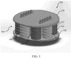
- FIG. 1 shows a disc replacement 100 that includes a first layer 102 having a lower surface for contacting a first vertebral bone.
- the disc replacement 100 includes a second layer 104 coupled to the first layer 102, the second layer 104 comprising a plurality of compressible column springs 106, 108.
- the disc replacement 100 includes a third layer 110 coupled to the second layer 104, the third layer 110 having an upper surface for contacting a second vertebral bone.
- Each of the plurality of compressible column springs includes a plurality of stacked coils, wherein each coil of each of the plurality of stacked coils has a spring constant (K).
- At least one of the plurality of compressible column springs includes a first coil 112 having a first spring constant and a second coil 114 having a second spring constant, wherein the first spring constant is different from the second spring constant.
- the natural intervertebral disc is a mechanical entity with viscoelastic properties whose attributes are correlated to the speed by which force is exerted on it.
- the compressible column spring is designed to have different K's along its length. This allows the disc replacement to respond differently to sudden impact versus gradually applied loads.
- the difference between resistance to impact and resistance to gradually built pressure is important to keep the vertebrae and the spinal column safe under impact while allowing freedom of movement under gradual application of pressure.
- the first layer 102 and third layer 110 have a thickness that varies such that the upper surface and lower surface of a single layer may not be parallel.
- This design of the layers provides patient specific lordosis and kyphosis.
- the disc replacement be asymmetric.
- the thickness of the layers themselves may not be constant, and the distance between the upper surface of the first layer and the lower surface of the third layer may vary. Further, the distance between the lower surface of the first layer and the upper surface of the third layer may also vary.
- the design also allows for patient-specific as well as level specific range of motion with as close to natural as possible free movement and resistance to movement.
- the spring constant of the plurality of coils can be varied.
- the height of a cross-section of a coil can be varied, as well as the pitch of the coils that make up the column springs. The pitch is defined as the distance in between a column spring's adjacent coils.
- the spring constant can also be varied by varying the materials used to make the spring. For example, if one coil of the spring is made from a first material and another coil of the spring is made from a second material having different elastic and deformation properties, the two coils will have different spring constants even if their dimensions are the same.
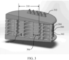
- Figure 3 shows a cross section of an intervertebral disc replacement.
- each coil has a cross section 300.
- the cross-section 300 of each coil has a substantially flat lower surface 302 and a substantially flat upper surface 304 that is substantially parallel to the substantially flat lower surface 302.
- the cross sections can be substantially rectangular.
- Each cross-section has a width 306 and a height 308.
- each column spring has an outer diameter 310 that is between about 3 mm and about 40 mm.
- the disc replacement can also have one or more fixation mechanisms 312 that engage the adjacent vertebra to fix the position of the disc replacement with respect to the vertebra.
- the fixation mechanisms can be spikes with tapered ends that contact the vertebra, though the embodiments of the invention are not limited to this design.
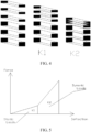
- Figure 4 illustrates the compression characteristics of the intervertebral disc replacement according to some embodiments.
- the left-hand portion of Figure 4 is a schematic illustration of a column spring having three upper coils with a first spring constant K1, and three lower coils with a second spring constant K2 that is greater than the first spring constant K1.
- the spring first compresses at a first rate determined primarily by the spring constant K1 of the upper springs.
- the lower springs undergo little or no compression.
- the spring then compresses at a second rate that is determined primarily by the second spring constant, K2.
- the lower coils compress at this second rate until they, too, are fully compressed.
- the disc replacement undergoes compression at a first rate when a compressive force is applied until a height of the disc replacement reaches a first predetermined value, and then the disc replacement undergoes compression at a second rate as the height of the disc replacement is further reduced, wherein the second rate is less than the first rate.
- the plurality of springs by virtue of their coil design will impart a different compliance to the disc replacement at low loads compared to high loads. At low loads and slower rate of load application the disc replacement will be compliant with low stiffness, and for high loads or rapid rates of load application the disc replacement will be stiff or non-compliant.
- Figures 4 and 5 illustrate a column spring with coils having two different spring constants
- the embodiments of the invention are not limited to column springs with coils with just two spring constants.
- a column spring may have coils of three or more spring constants. Coils having the same spring constant may be grouped together within the column spring, or may be interspersed throughout the column spring. Further, when a compressive force is applied to a spring, coils within the spring having different spring constants may undergo compression at the same time, but at different rates.
- a disc replacement may comprise a single column spring.
- the coils of the single column spring may have one or more spring constants.
- a disc replacement according to some embodiments may include a plurality of column springs, each having a single spring constant along its length. The spring constants of the plurality of column springs may all be the same, or may vary from column spring to column spring.
- Figure 6 shows an intervertebral disc replacement with beveled coils according to some additional embodiments
- Figure 7 shows the first and second layers of the disc replacement of Figure 6 .
- the coils of the column springs can have edges that are beveled or rounded.
- the coils have a cross-section with a flat upper surface and a flat lower surface, but the cross-section is not a rectangle like the cross-section 300 in Figure 3 .
- the cross-section has a maximum width, and each of the flat upper surface and the flat lower surface has a width that is at least 30% of the maximum width.
- each of the flat upper surface and the flat lower surface has a width that is at least 90% of the maximum width.
- the flat upper and lower surfaces of the cross-sections of the coils creates a large surface area over which pressure can be distributed. If the coils are sufficiently compressed that they come into contact with each other, the forces applied by one coil on an adjacent coil are spread out over the flat surface, reducing the pressure at any single point. If the coils had a circular cross-section, each coil would contact its neighbor at only the top or bottom point of the cross-section, concentrating the force on that point. This potentially leads to wear and the release of debris as pieces of the spring break off due to excessive force.
- the design of the coils according to some embodiments of the invention prevents erosion of the coils by distributing forces over a larger surface area. When the column spring is uncompressed or partially compressed, a space exists between adjacent coils of a given spring, allowing the disc replacement to absorb shock exerted on the spine.
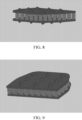
- Figures 8-10 shows an intervertebral disc replacement undergoing complete compression.
- Figure 8 shows how the coils of the column springs are maximally compressed. Each coil, with the exclusion of the upper-most and lower-most coils, comes into contact with the coils above and below it such that the distance between the first layer and the third layer reaches a minimum value, beyond which the disc replacement can no longer be compressed.
- the intervertebral disc replacement can thus be designed to have a minimum height that is predetermined based on the patient's physiology.
- Figure 9 shows a cross-section of the disc replacement shown in Figure 8 .
- the cross-sections of the coils are visible, showing how the flat upper surface of each coil, with the exclusion of the upper-most coils, contacts the flat lower surface of the coil above it. This distributes the forces on each coil over a larger area, thereby reducing the pressure at any single point.
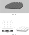
- Figure 10 shows the first and second layers of the disc replacement shown in Figures 8 and 9 . While Figure 10 shows that all the column springs become maximally compressed at the same height, the embodiments of the invention are not limited to this concept.
- the minimum height of the disc replacement may be determined by the maximally-compressed height of one or more of the springs. Further, the minimum height might be different for different regions of the disc replacement. For example, the middle of the disc replacement may be compressible to a first minimum height, while the outer edges of the disc replacement may be further compressed to a second minimum height.
- Figure 11 shows additional images of a fully-compressed disc replacement.
- the intervertebral disc replacement includes a barrier disposed between the first layer and the third layer and surrounding the second layer.
- a disc replacement including a barrier is shown in Figure 12 .
- the barrier 1200 surrounds the second layer, preventing the body from protruding or growing into the area of the column springs, thus protecting the springs from interference by the body.
- the barrier may be made of one or more of Gortex, polycarbonate, silastic, and any biocompatible membrane or tissue.
- the barrier may be made of a material that is impermeable and wear resistant.
- the barrier may be mechanically or chemically bonded to the upper and lower layers, or both mechanically and chemically bonded.
- the barrier may form a fluid-tight seal with the first layer and the third layer.
- FIG. 13 An intervertebral disc replacement comprising two layers of column springs according to some embodiments of the invention is shown in Figure 13 .
- the second layer includes a first plurality of compressible column springs 1300 attached to the upper surface of the first layer, a second plurality of compressible column springs 1302 attached to the lower surface of the third layer, and a fourth layer 1304 disposed between and attached to the first plurality of compressible column springs 1300 and the second plurality of compressible column springs 1302.
- Figure 14 shows the intervertebral disc replacement of Figure 13 wherein the top plate has been rendered transparent.
- Figure 15 shows a side view of the disc replacement shown in Figures 13 and 14 .
- At least one of the plurality of compressible column springs in the intervertebral disc replacement includes coils that are wound clockwise, and at least one of the plurality of compressible column springs includes coils that are wound counter-clockwise, as shown in Figure 1 .
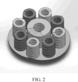
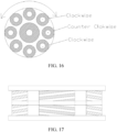
- Figure 16 shows a disc replacement in which the clockwise- and counter-clockwise-wound coils are alternated. This can enhance the stability of the disc replacement, and can prevent overrotation.
- Figure 17 illustrates a disc replacement having a first plurality of column springs disposed below a second plurality of column springs. As shown in Figure 17 , the lower coils can be wound in the same direction as their upper counterparts, or can be would in the opposite direction.
- Figure 18 shows a single compressible column spring according to some embodiments. When maximally compressed, the spring makes a continuous column.
- the embodiments of the invention are not limited to column springs having rectangular cross-sections like the one shown in Figure 18 .
- the edges of the coils may be shaved or rounded such that, when maximally compressed, the spring forms a column whose outer surface is uneven, different from that of a straight cylinder.
- FIG 19 An intervertebral disc replacement according to some additional embodiments is shown in Figure 19 .
- the intervertebral disc replacement has a second layer comprising a compressible lattice.
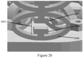
- Figure 20 shows a zoomed-in image of the compressible lattice according to some embodiments.
- the compressible lattice can be formed from layers of springs, or "struts.”
- each strut 2000 has an O-like shape that can be compressed, thereby reducing the height of the strut, and can expand and/or return to its original state depending upon the forces being applied.
- the struts can be of a shape-memory type so that when the compressive forces are removed, the struts return to their original position.
- Each strut can further comprise a stopper 2002.
- the stopper 2002 can be any mechanism that limits the extent to which the strut 2000 can be compressed, thereby preventing mechanical failure of the strut 100 due to excessive compression. The stoppers thus provide an elastic limit so that the struts do not fatigue or fracture.
- the stopper 2002 comprises two T-like features, an upright T-like feature 2004, and an inverted T-like feature 2006, disposed within the O-like strut 2000.
- the T-like features 2004, 2006 are brought nearer to each other.
- the compression continues until the two T-like features 2004, 2006 come into contact with one another.
- the features prevent the strut from further compressing, providing a minimum displacement between the top and bottom layers of the disc replacement.
- the elasticity and/or shape memory of the struts can allow the device to accommodate expansion and compression.
- the lattice structure shown in the figures undergoes almost no lateral expansion when the disc replacement is compressed vertically.
- the compressive quality of the lattice can be a result of the compressive design of each of the struts.
- the compressive lattice can be finely tuned to mimic the compressive characteristics of a native disc. For example, certain areas of the compressive lattice can be designed to be more or less resistant to compression, essentially changing the spring constant. One can thus design regions of the disc replacement known to experience greater forces to be less compliant, while less load-bearing areas can be more compressible.
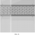
- Figure 21 shows a side view of an intervertebral disc replacement comprising a compressible lattice.
- Figure 22 shows a cross-section of an intervertebral disc replacement comprising a compressible lattice.
- Figure 23 shows the first and second layers of an intervertebral disc replacement comprising a compressible lattice.
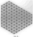
- Figure 24 shows a top view of the compressible lattice.
- the lattice has a repeating hexagonal structure. While the lattices shown in the figures have a regular, repeating structure, the shape and size of the individual elements can in fact be varied. For example, in some regions the lattice can be thicker to provide additional support and resistance to compression.
- the lattice is also not limited to the number of layers shown in the figures.
- the lattice could comprise more or fewer layers, and the struts could be made larger or smaller.
- the springs within the lattice may have different diameters and thicknesses, and the spacing between them may vary. These parameters may be adjusted such that different regions have different compressive and rotational qualities, allowing the disc replacement to mimic the movement of a native disc.
- the intervertebral disc replacement is fabricated using 3D printing.
- a powder-based 3D printer such as a powder and laser-based 3D printer, can be used to form the first layer, the second layer comprising a plurality of column springs, and the third layer.
- the disc replacement can be formed as a single piece, or as multiple pieces that are then connected.
- the column springs are printed directly on top of the first layer, and the third layer is printed on top of the plurality of column springs.
- each layer can be printed directly on the layer below it.
- the disc replacement may also be inverted such that the layer that will be uppermost in the patient's body is printed first.
- the disc replacement comprises one or more of titanium, nitinol, cobalt chrome, high density polycarbonate, and any other material used for implants in the human body. Titanium can be advantageous because it is not magnetic or ferromagnetic, and is biocompatible. All biocompatible materials are contemplated in accordance with the principles of the invention.
- the 3D printing process includes printing using multiple materials in a single disc.
- the first and/or third layer may be printed using a first material, while the plurality of column springs is printed using a second material.
- the column springs themselves may comprise more than one material.
- different materials may be used to vary the spring constant within a single column spring, or from one column spring to the next.
- Multiple materials may also be used to form the first layer and the third layer.
- the first layer may comprise different material(s) than the third layer according to some embodiments.
- the disc replacement is formed using sintering.
- Sintering is the process of compacting and forming a solid mass of material by heat and/or pressure without melting it to the point of liquefaction.
- the embodiments of the invention are not limited to 3D printing and sintering, and other appropriate manufacturing methods may also be implemented.
- the device can be 3D printed, its shape, as well as its compressive and rotational characteristics, can be patient-specific.
- the surface area of the first and third layers may appear elliptical, kidney shaped, oval, or trapezoidal from a top-down view, while appearing scalloped or winged from a cross-sectional view, for example.
- the dimensions of the disc replacement are patient-specific, designed to match the size of the native disc, and meet the rotational, compressive, and load-bearing requirements of the native disc that will be replaced.
- the design of the disc replacement may take into account data from an X-ray, a magnetic resonance image (MRI), or a computer tomography (CT) scan.
- the disc replacement may also be tailored in a patient specific manner taking into account the exact patient disc geometry from X-ray/MRI/ CT, the disc level (each disc level requires different mechanical properties), the weight of the patient body portion above the disc, etc. Based on these factors, the disc replacement will be a patient specific disc in which the end plates and their angle, the disc replacement's volume, its springs geometry (both the individual construction of each spring and its resistance, as well as number of springs and their disposition along the disc area) are all tailored to meet the exact needs of the patient.
Landscapes
- Health & Medical Sciences (AREA)
- Engineering & Computer Science (AREA)
- Biomedical Technology (AREA)
- Orthopedic Medicine & Surgery (AREA)
- Neurology (AREA)
- Cardiology (AREA)
- Vascular Medicine (AREA)
- Manufacturing & Machinery (AREA)
- Chemical & Material Sciences (AREA)
- Oral & Maxillofacial Surgery (AREA)
- Transplantation (AREA)
- Heart & Thoracic Surgery (AREA)
- Materials Engineering (AREA)
- Life Sciences & Earth Sciences (AREA)
- Animal Behavior & Ethology (AREA)
- General Health & Medical Sciences (AREA)
- Public Health (AREA)
- Veterinary Medicine (AREA)
- Prostheses (AREA)
Claims (14)
- Bandscheibenersatz, umfassend:eine erste Schicht, die eine untere Oberfläche zum Berühren eines ersten Wirbelknochens aufweist;eine zweite Schicht, die mit der ersten Schicht gekoppelt ist, die zweite Schicht umfassend eine Vielzahl von komprimierbaren Säulenfedern; undeine dritte Schicht, die mit der zweiten Schicht gekoppelt ist, wobei die dritte Schicht eine obere Oberfläche zum Berühren eines zweiten Wirbelknochens aufweist,wobei die erste Schicht, die zweite Schicht und die dritte Schicht ein einheitliches Stück sind,wobei die erste Schicht und die dritte Schicht eine Dicke aufweisen, die variiert,wobei jede der Vielzahl von komprimierbaren Säulenfedern eine Vielzahl von gestapelten Spulen umfasst,wobei jede Spule von jeder der Vielzahl von gestapelten Spulen eine Federkonstante (K) aufweist undwobei mindestens eine der Vielzahl von komprimierbaren Säulenfedern eine erste Spule, die eine erste Federkonstante aufweist, und eine zweite Spule umfasst, umfassend eine zweite Federkonstante, wobei sich die erste Federkonstante von der zweiten Federkonstante unterscheidet.
- Bandscheibenersatz nach Anspruch 1, wobei mindestens eine zweite komprimierbare Säulenfeder der Vielzahl von komprimierbaren Säulenfedern eine Spule umfasst, die eine dritte Federkonstante aufweist, wobei sich die dritte Federkonstante von mindestens einer von der ersten und der zweiten Federkonstante unterscheidet.
- Bandscheibenersatz nach Anspruch 1, wobei der Bandscheibenersatz einer Kompression bei einer ersten Geschwindigkeit unterzogen wird, wenn eine komprimierende Kraft ausgeübt wird, bis eine Höhe des Bandscheibenersatzes einen ersten zuvor bestimmten Wert erreicht, und wobei der Bandscheibenersatz der Kompression bei einer zweiten Geschwindigkeit unterzogen wird, während die Höhe des Bandscheibenersatzes weiter reduziert wird, wobei die zweite Geschwindigkeit kleiner als die erste Geschwindigkeit ist,
wobei insbesondere jede der ersten Schicht und der dritten Schicht eine Vielzahl von Fixierungsmechanismen aufweist, die in den ersten Wirbelknochen oder den zweiten Wirbelknochen eingreift, um eine Position des Bandscheibenersatzes in Bezug auf den ersten und den zweiten Wirbelknochen zu fixieren. - Bandscheibenersatz nach Anspruch 1, wobei jede Spule einen Querschnitt aufweist, wobei der Querschnitt jeder Spule eine flache untere Oberfläche und eine flache obere Oberfläche aufweist, die parallel zu der flachen unteren Oberfläche ist,
wobei, insbesondere, wenn eine Säulenfeder der Vielzahl von komprimierbaren Säulenfedern maximal komprimiert ist, die untere flache Oberfläche und die obere flache Oberfläche angrenzender Spulen einander berühren, wodurch eine kontinuierliche Säule ohne Raum zwischen angrenzenden Spulen ausgebildet wird, und wobei eine Höhe der kontinuierlichen Säule eine zuvor bestimmte Grenze definiert, über die hinweg der Bandscheibenersatz nicht komprimiert werden kann. - Bandscheibenersatz nach Anspruch 4, wobei insbesondere jeder Querschnitt eine maximale Breite aufweist, undwobei jede der flachen oberen Oberfläche und der flachen unteren Oberfläche eine Breite aufweist, die mindestens 30 % der maximalen Breite oder mindestens 90 % der maximalen Breite beträgt,wobei, insbesondere, jeder Querschnitt im Wesentlichen rechteckig ist.
- Bandscheibenersatz nach Anspruch 1, wobei die Vielzahl von komprimierbaren Säulenfedern in einem oder mehreren konzentrischen Ringen um eine Bewegungsmitte des Bandscheibenersatzes herum angeordnet ist,wobei insbesondere mindestens eine der Vielzahl von komprimierbaren Säulenfedern Spulen umfasst, die im Uhrzeigersinn gewickelt sind, undwobei mindestens eine der Vielzahl von komprimierbaren Säulenfedern Spulen umfasst, die gegen den Uhrzeigersinn gewickelt sind.
- Bandscheibenersatz nach Anspruch 1, wobei die Bandscheibenersatzvorrichtung komprimierendes, Extensions-, Flexions- und Rotationsverhalten einer menschlichen Bandscheibe nachahmt.
- Bandscheibenersatz nach Anspruch 1, ferner umfassend eine Barriere, die an der ersten Schicht und der dritten Schicht angebracht ist und die zweite Schicht umschließt, wobei die Barriere eine fluiddichte Dichtung mit der ersten Schicht und der dritten Schicht ausbildet.
- Bandscheibenersatz nach Anspruch 1, wobei jede Säulenfeder einen Außenumfang zwischen etwa 3 mm und etwa 40 mm aufweist,
wobei insbesondere der Bandscheibenersatz eines oder mehrere von Titan, Nitinol, Kobaltchrom und hochdichtem Polycarbonat umfasst. - Bandscheibenersatz nach Anspruch 1, wobei jede der Vielzahl von komprimierbaren Säulenfedern eine Höhe aufweist, die abnimmt, wenn eine komprimierende Kraft ausgeübt wird, und eine Struktur, die verhindert, dass die Höhe über eine zuvor bestimmte Grenze hinaus abnimmt,
wobei insbesondere ein Unterschied zwischen der ersten Federkonstante und der zweiten Federkonstante durch einen Unterschied in mindestens einem von einer Gruppe bestimmt wird, bestehend aus einer Höhe eines Querschnitts, einer Breite eines Querschnitts, einer Steigung und einem Material der ersten Spule und der zweiten Spule. - Bandscheibenersatz nach Anspruch 1, wobei die zweite Schicht umfasst:eine erste Vielzahl von komprimierbaren Säulenfedern, die an der oberen Oberfläche der ersten Schicht angebracht ist;eine zweite Vielzahl von komprimierbaren Säulenfedern, die an der unteren Oberfläche der dritten Schicht angebracht ist; undeine vierte Schicht, die zwischen der ersten Vielzahl von komprimierbaren Säulenfedern und der zweiten Vielzahl von komprimierbaren Säulenfedern angeordnet und an dieser angebracht ist.
- Verfahren zum Herstellen eines Bandscheibenersatzes, das Verfahren umfassend:Ausbilden, unter Verwendung eines pulverbasierten 3D-Druckers, einer ersten Schicht;Ausbilden, unter Verwendung des pulverbasierten 3D-Druckers, einer zweiten Schicht auf der ersten Schicht, die zweite Schicht umfassend eine Vielzahl von komprimierbaren Säulenfedern;Ausbilden, unter Verwendung des pulverbasierten 3D-Druckers, einer dritten Schicht auf der zweiten Schicht; undEntfernen von ungebundenen Pulvern aus der Vielzahl von komprimierbaren Säulenfedern,wobei die erste Schicht, die zweite Schicht und die dritte Schicht ein einheitliches Stück sind,wobei die erste Schicht und die dritte Schicht eine Dicke aufweisen, die variiert,wobei jede der Vielzahl von komprimierbaren Säulenfedern eine Vielzahl von gestapelten Spulen umfasst,wobei jede Spule von jeder der Vielzahl von gestapelten Spulen eine Federkonstante aufweist, undwobei mindestens eine der Vielzahl von komprimierbaren Säulenfedern ausgebildet ist, um eine erste Spule, die eine erste Federkonstante aufweist, und eine zweite Spule einzuschließen, die eine zweite Federkonstante aufweist, wobei sich die erste Federkonstante von der zweiten Federkonstante unterscheidet.
- Verfahren zum Herstellen eines Bandscheibenersatzes nach Anspruch 12, ferner umfassend:vor dem Ausbilden des Bandscheibenersatzes, Erhalten von Daten, umfassend mindestens eines von Röntgen, Magnetresonanzbildgebung (MRT), Computertomographie (CT), Patientenkörpermasse über dem Bandscheibenersatz; undBestimmen von Winkeln der ersten Schicht und der dritten Schicht und einer Position jeder der Vielzahl von komprimierbaren Säulenfedern und der Federkonstante jeder der Vielzahl von gestapelten Spulen basierend auf den erhaltenen Daten, um den patientenspezifischen Grad an Lordose- und Bewegungsanforderungen zu entsprechen.
- Verfahren zum Herstellen eines Bandscheibenersatzes nach Anspruch 12, wobei das Ausbilden der zweiten Schicht umfasst:Ausbilden, unter Verwendung des pulverbasierten 3D-Druckers, einer ersten Vielzahl von komprimierbaren Säulenfedern, die an einer oberen Oberfläche der ersten Schicht angebracht ist;Ausbilden, unter Verwendung des pulverbasierten 3D-Druckers, einer vierten Schicht, die an der ersten Vielzahl von komprimierbaren Säulenfedern angebracht ist; undAusbilden, unter Verwendung des pulverbasierten 3D-Druckers, einer zweiten Vielzahl von komprimierbaren Säulenfedern, die an der vierten Schicht und einer unteren Oberfläche der dritten Schicht angebracht ist.
Applications Claiming Priority (2)
| Application Number | Priority Date | Filing Date | Title |
|---|---|---|---|
| US15/234,923 US10390959B2 (en) | 2015-11-24 | 2016-08-11 | Intervertebral disc replacement |
| PCT/US2017/046339 WO2018031801A1 (en) | 2016-08-11 | 2017-08-10 | Intervertebral disc replacement |
Publications (5)
| Publication Number | Publication Date |
|---|---|
| EP3496636A1 EP3496636A1 (de) | 2019-06-19 |
| EP3496636A4 EP3496636A4 (de) | 2020-04-22 |
| EP3496636C0 EP3496636C0 (de) | 2023-12-13 |
| EP3496636B1 true EP3496636B1 (de) | 2023-12-13 |
| EP3496636B8 EP3496636B8 (de) | 2024-01-24 |
Family
ID=66520318
Family Applications (1)
| Application Number | Title | Priority Date | Filing Date |
|---|---|---|---|
| EP17840294.7A Active EP3496636B8 (de) | 2016-08-11 | 2017-08-10 | Bandscheibenersatz |
Country Status (3)
| Country | Link |
|---|---|
| EP (1) | EP3496636B8 (de) |
| CA (1) | CA3033354A1 (de) |
| WO (1) | WO2018031801A1 (de) |
Family Cites Families (7)
| Publication number | Priority date | Publication date | Assignee | Title |
|---|---|---|---|---|
| CA1283501C (en) * | 1987-02-12 | 1991-04-30 | Thomas P. Hedman | Artificial spinal disc |
| US20020128714A1 (en) * | 1999-06-04 | 2002-09-12 | Mark Manasas | Orthopedic implant and method of making metal articles |
| BR0313499A (pt) * | 2002-08-15 | 2005-07-05 | David Gerber | Disco intervertebral |
| EP1651150B1 (de) * | 2003-08-07 | 2021-03-24 | Dynamic Spine, Inc. | Intervertebral-prothesenvorrichtung und relevante vorrichtungen und verfahren zur implantation der intervertebralen prothesenvorrichtung |
| US7309357B2 (en) * | 2004-12-30 | 2007-12-18 | Infinesse, Corporation | Prosthetic spinal discs |
| US7578848B2 (en) * | 2005-03-03 | 2009-08-25 | Cervical Xpand, Llc | Intervertebral stabilizer |
| AU2016366191B2 (en) * | 2015-12-07 | 2019-10-03 | Nexus Spine, L.L.C. | Porous interbody spacer |
-
2017
- 2017-08-10 EP EP17840294.7A patent/EP3496636B8/de active Active
- 2017-08-10 CA CA3033354A patent/CA3033354A1/en active Pending
- 2017-08-10 WO PCT/US2017/046339 patent/WO2018031801A1/en not_active Ceased
Also Published As
| Publication number | Publication date |
|---|---|
| EP3496636A4 (de) | 2020-04-22 |
| EP3496636C0 (de) | 2023-12-13 |
| CA3033354A1 (en) | 2018-02-15 |
| EP3496636A1 (de) | 2019-06-19 |
| WO2018031801A1 (en) | 2018-02-15 |
| EP3496636B8 (de) | 2024-01-24 |
Similar Documents
| Publication | Publication Date | Title |
|---|---|---|
| US10390959B2 (en) | Intervertebral disc replacement | |
| US7309357B2 (en) | Prosthetic spinal discs | |
| US8298287B2 (en) | Intervertebral motion disc with helical shock absorber | |
| US9636234B2 (en) | Hybrid intervertebral disc spacer device and method of manufacturing the same | |
| US8236055B2 (en) | Intervertebral prosthesis for supporting adjacent vertebral bodies enabling the creation of soft fusion and method | |
| KR101052833B1 (ko) | 유연성을 갖는 척추체간 케이지 | |
| US10925749B2 (en) | Intervertebral cage and method of treating vertebrae with an intervertebral cage | |
| Eijkelkamp et al. | Requirements for an artificial intervertebral disc | |
| US20090105835A1 (en) | Vertebral Body Replacement and Method for Spanning a Space Formed upon Removal of a Vertebral Body | |
| US11298931B2 (en) | Intervertebral disc replacement | |
| Biswas et al. | Optimization of spinal implant screw for lower vertebra through finite element studies | |
| WO2011016989A2 (en) | Toroid-shaped spinal disc | |
| WO2017190236A1 (en) | Vertebral implant | |
| EP3496636B1 (de) | Bandscheibenersatz | |
| US12447023B2 (en) | Cervical cage | |
| RU2465870C1 (ru) | Протез межпозвоночного диска | |
| EP3597154A1 (de) | Magnetische bandscheibenersatzvorrichtungen | |
| Mabrouk et al. | A biomechanical analysis of prosthesis disc in lumbar spinal segment using three-dimensional finite element modelling | |
| Borkowski et al. | Finite element analysis of artificial disc with an elastomeric core in the lumbar spine | |
| Lin et al. | Finite element analysis of cervical spine with different constrained types of total disc replacement | |
| Pan et al. | Biomechanical effects of the CoflexTM implantation on the lumbar spine. A nonlinear finite element analysis | |
| US20100249932A1 (en) | Materials, Devices and Methods for Intervertebral Stabilization Via Use of In Situ Shape Recovery | |
| Sharma et al. | Finite Element Modelling and Comparative Assessment of Single-Level Cervical Disc Replacement with Fusion Surgery | |
| Gao et al. | Design of Posterior Lumbar Fusion Internal Fixation Screws | |
| Kubiak | Design and evaluation of devices for the treatment of intervertebral disorders |
Legal Events
| Date | Code | Title | Description |
|---|---|---|---|
| STAA | Information on the status of an ep patent application or granted ep patent |
Free format text: STATUS: THE INTERNATIONAL PUBLICATION HAS BEEN MADE |
|
| PUAI | Public reference made under article 153(3) epc to a published international application that has entered the european phase |
Free format text: ORIGINAL CODE: 0009012 |
|
| STAA | Information on the status of an ep patent application or granted ep patent |
Free format text: STATUS: REQUEST FOR EXAMINATION WAS MADE |
|
| 17P | Request for examination filed |
Effective date: 20190301 |
|
| AK | Designated contracting states |
Kind code of ref document: A1 Designated state(s): AL AT BE BG CH CY CZ DE DK EE ES FI FR GB GR HR HU IE IS IT LI LT LU LV MC MK MT NL NO PL PT RO RS SE SI SK SM TR |
|
| AX | Request for extension of the european patent |
Extension state: BA ME |
|
| RAP1 | Party data changed (applicant data changed or rights of an application transferred) |
Owner name: AGADA MEDICAL LTD. |
|
| DAV | Request for validation of the european patent (deleted) | ||
| DAX | Request for extension of the european patent (deleted) | ||
| A4 | Supplementary search report drawn up and despatched |
Effective date: 20200319 |
|
| RIC1 | Information provided on ipc code assigned before grant |
Ipc: A61F 2/30 20060101ALI20200313BHEP Ipc: A61B 17/86 20060101ALI20200313BHEP Ipc: A61B 17/70 20060101ALI20200313BHEP Ipc: A61F 2/44 20060101ALI20200313BHEP Ipc: A61B 17/56 20060101AFI20200313BHEP Ipc: A61B 17/58 20060101ALI20200313BHEP Ipc: B33Y 80/00 20150101ALI20200313BHEP Ipc: A61F 2/28 20060101ALI20200313BHEP Ipc: A61F 2/00 20060101ALI20200313BHEP Ipc: A61B 17/68 20060101ALI20200313BHEP Ipc: B29L 31/00 20060101ALI20200313BHEP |
|
| GRAP | Despatch of communication of intention to grant a patent |
Free format text: ORIGINAL CODE: EPIDOSNIGR1 |
|
| STAA | Information on the status of an ep patent application or granted ep patent |
Free format text: STATUS: GRANT OF PATENT IS INTENDED |
|
| RIC1 | Information provided on ipc code assigned before grant |
Ipc: B29L 31/00 20060101ALI20230622BHEP Ipc: B33Y 80/00 20150101ALI20230622BHEP Ipc: A61F 2/44 20060101ALI20230622BHEP Ipc: A61F 2/30 20060101ALI20230622BHEP Ipc: A61F 2/28 20060101ALI20230622BHEP Ipc: A61F 2/00 20060101ALI20230622BHEP Ipc: A61B 17/86 20060101ALI20230622BHEP Ipc: A61B 17/70 20060101ALI20230622BHEP Ipc: A61B 17/68 20060101ALI20230622BHEP Ipc: A61B 17/58 20060101ALI20230622BHEP Ipc: A61B 17/56 20060101AFI20230622BHEP |
|
| INTG | Intention to grant announced |
Effective date: 20230707 |
|
| GRAS | Grant fee paid |
Free format text: ORIGINAL CODE: EPIDOSNIGR3 |
|
| GRAA | (expected) grant |
Free format text: ORIGINAL CODE: 0009210 |
|
| STAA | Information on the status of an ep patent application or granted ep patent |
Free format text: STATUS: THE PATENT HAS BEEN GRANTED |
|
| AK | Designated contracting states |
Kind code of ref document: B1 Designated state(s): AL AT BE BG CH CY CZ DE DK EE ES FI FR GB GR HR HU IE IS IT LI LT LU LV MC MK MT NL NO PL PT RO RS SE SI SK SM TR |
|
| REG | Reference to a national code |
Ref country code: GB Ref legal event code: FG4D |
|
| REG | Reference to a national code |
Ref country code: CH Ref legal event code: EP |
|
| REG | Reference to a national code |
Ref country code: DE Ref legal event code: R096 Ref document number: 602017077533 Country of ref document: DE |
|
| REG | Reference to a national code |
Ref country code: DE Ref legal event code: R081 Ref document number: 602017077533 Country of ref document: DE Owner name: AGADA MEDICAL LTD., IL Free format text: FORMER OWNER: AGADA MEDICAL LTD., ZICHRON YAAKOV, IL |
|
| REG | Reference to a national code |
Ref country code: CH Ref legal event code: PK Free format text: BERICHTIGUNG B8 |
|
| REG | Reference to a national code |
Ref country code: IE Ref legal event code: FG4D |
|
| RAP4 | Party data changed (patent owner data changed or rights of a patent transferred) |
Owner name: AGADA MEDICAL LTD. |
|
| U01 | Request for unitary effect filed |
Effective date: 20240112 |
|
| U07 | Unitary effect registered |
Designated state(s): AT BE BG DE DK EE FI FR IT LT LU LV MT NL PT SE SI Effective date: 20240123 |
|
| PG25 | Lapsed in a contracting state [announced via postgrant information from national office to epo] |
Ref country code: GR Free format text: LAPSE BECAUSE OF FAILURE TO SUBMIT A TRANSLATION OF THE DESCRIPTION OR TO PAY THE FEE WITHIN THE PRESCRIBED TIME-LIMIT Effective date: 20240314 |
|
| PG25 | Lapsed in a contracting state [announced via postgrant information from national office to epo] |
Ref country code: ES Free format text: LAPSE BECAUSE OF FAILURE TO SUBMIT A TRANSLATION OF THE DESCRIPTION OR TO PAY THE FEE WITHIN THE PRESCRIBED TIME-LIMIT Effective date: 20231213 |
|
| PG25 | Lapsed in a contracting state [announced via postgrant information from national office to epo] |
Ref country code: GR Free format text: LAPSE BECAUSE OF FAILURE TO SUBMIT A TRANSLATION OF THE DESCRIPTION OR TO PAY THE FEE WITHIN THE PRESCRIBED TIME-LIMIT Effective date: 20240314 Ref country code: ES Free format text: LAPSE BECAUSE OF FAILURE TO SUBMIT A TRANSLATION OF THE DESCRIPTION OR TO PAY THE FEE WITHIN THE PRESCRIBED TIME-LIMIT Effective date: 20231213 |
|
| PG25 | Lapsed in a contracting state [announced via postgrant information from national office to epo] |
Ref country code: RS Free format text: LAPSE BECAUSE OF FAILURE TO SUBMIT A TRANSLATION OF THE DESCRIPTION OR TO PAY THE FEE WITHIN THE PRESCRIBED TIME-LIMIT Effective date: 20231213 Ref country code: NO Free format text: LAPSE BECAUSE OF FAILURE TO SUBMIT A TRANSLATION OF THE DESCRIPTION OR TO PAY THE FEE WITHIN THE PRESCRIBED TIME-LIMIT Effective date: 20240313 Ref country code: HR Free format text: LAPSE BECAUSE OF FAILURE TO SUBMIT A TRANSLATION OF THE DESCRIPTION OR TO PAY THE FEE WITHIN THE PRESCRIBED TIME-LIMIT Effective date: 20231213 |
|
| PG25 | Lapsed in a contracting state [announced via postgrant information from national office to epo] |
Ref country code: IS Free format text: LAPSE BECAUSE OF FAILURE TO SUBMIT A TRANSLATION OF THE DESCRIPTION OR TO PAY THE FEE WITHIN THE PRESCRIBED TIME-LIMIT Effective date: 20240413 |
|
| PG25 | Lapsed in a contracting state [announced via postgrant information from national office to epo] |
Ref country code: CZ Free format text: LAPSE BECAUSE OF FAILURE TO SUBMIT A TRANSLATION OF THE DESCRIPTION OR TO PAY THE FEE WITHIN THE PRESCRIBED TIME-LIMIT Effective date: 20231213 |
|
| PG25 | Lapsed in a contracting state [announced via postgrant information from national office to epo] |
Ref country code: SK Free format text: LAPSE BECAUSE OF FAILURE TO SUBMIT A TRANSLATION OF THE DESCRIPTION OR TO PAY THE FEE WITHIN THE PRESCRIBED TIME-LIMIT Effective date: 20231213 |
|
| PG25 | Lapsed in a contracting state [announced via postgrant information from national office to epo] |
Ref country code: SM Free format text: LAPSE BECAUSE OF FAILURE TO SUBMIT A TRANSLATION OF THE DESCRIPTION OR TO PAY THE FEE WITHIN THE PRESCRIBED TIME-LIMIT Effective date: 20231213 Ref country code: SK Free format text: LAPSE BECAUSE OF FAILURE TO SUBMIT A TRANSLATION OF THE DESCRIPTION OR TO PAY THE FEE WITHIN THE PRESCRIBED TIME-LIMIT Effective date: 20231213 Ref country code: RO Free format text: LAPSE BECAUSE OF FAILURE TO SUBMIT A TRANSLATION OF THE DESCRIPTION OR TO PAY THE FEE WITHIN THE PRESCRIBED TIME-LIMIT Effective date: 20231213 Ref country code: IS Free format text: LAPSE BECAUSE OF FAILURE TO SUBMIT A TRANSLATION OF THE DESCRIPTION OR TO PAY THE FEE WITHIN THE PRESCRIBED TIME-LIMIT Effective date: 20240413 Ref country code: CZ Free format text: LAPSE BECAUSE OF FAILURE TO SUBMIT A TRANSLATION OF THE DESCRIPTION OR TO PAY THE FEE WITHIN THE PRESCRIBED TIME-LIMIT Effective date: 20231213 |
|
| PG25 | Lapsed in a contracting state [announced via postgrant information from national office to epo] |
Ref country code: PL Free format text: LAPSE BECAUSE OF FAILURE TO SUBMIT A TRANSLATION OF THE DESCRIPTION OR TO PAY THE FEE WITHIN THE PRESCRIBED TIME-LIMIT Effective date: 20231213 |
|
| PG25 | Lapsed in a contracting state [announced via postgrant information from national office to epo] |
Ref country code: PL Free format text: LAPSE BECAUSE OF FAILURE TO SUBMIT A TRANSLATION OF THE DESCRIPTION OR TO PAY THE FEE WITHIN THE PRESCRIBED TIME-LIMIT Effective date: 20231213 |
|
| REG | Reference to a national code |
Ref country code: DE Ref legal event code: R097 Ref document number: 602017077533 Country of ref document: DE |
|
| U20 | Renewal fee for the european patent with unitary effect paid |
Year of fee payment: 8 Effective date: 20240827 |
|
| PLBE | No opposition filed within time limit |
Free format text: ORIGINAL CODE: 0009261 |
|
| STAA | Information on the status of an ep patent application or granted ep patent |
Free format text: STATUS: NO OPPOSITION FILED WITHIN TIME LIMIT |
|
| 26N | No opposition filed |
Effective date: 20240916 |
|
| REG | Reference to a national code |
Ref country code: CH Ref legal event code: PL |
|
| PG25 | Lapsed in a contracting state [announced via postgrant information from national office to epo] |
Ref country code: MC Free format text: LAPSE BECAUSE OF FAILURE TO SUBMIT A TRANSLATION OF THE DESCRIPTION OR TO PAY THE FEE WITHIN THE PRESCRIBED TIME-LIMIT Effective date: 20231213 Ref country code: CH Free format text: LAPSE BECAUSE OF NON-PAYMENT OF DUE FEES Effective date: 20240831 |
|
| PG25 | Lapsed in a contracting state [announced via postgrant information from national office to epo] |
Ref country code: IE Free format text: LAPSE BECAUSE OF NON-PAYMENT OF DUE FEES Effective date: 20240810 |
|
| U20 | Renewal fee for the european patent with unitary effect paid |
Year of fee payment: 9 Effective date: 20250827 |
|
| PGFP | Annual fee paid to national office [announced via postgrant information from national office to epo] |
Ref country code: GB Payment date: 20250821 Year of fee payment: 9 |
|
| PG25 | Lapsed in a contracting state [announced via postgrant information from national office to epo] |
Ref country code: CY Free format text: LAPSE BECAUSE OF FAILURE TO SUBMIT A TRANSLATION OF THE DESCRIPTION OR TO PAY THE FEE WITHIN THE PRESCRIBED TIME-LIMIT; INVALID AB INITIO Effective date: 20170810 |
|
| PG25 | Lapsed in a contracting state [announced via postgrant information from national office to epo] |
Ref country code: HU Free format text: LAPSE BECAUSE OF FAILURE TO SUBMIT A TRANSLATION OF THE DESCRIPTION OR TO PAY THE FEE WITHIN THE PRESCRIBED TIME-LIMIT; INVALID AB INITIO Effective date: 20170810 |