EP3497703B1 - Keramische materialverbundstruktur zur verwendung in einer kernreaktorumgebung und verfahren zur herstellung einer vorform für eine solche keramische materialverbundstruktur - Google Patents
Keramische materialverbundstruktur zur verwendung in einer kernreaktorumgebung und verfahren zur herstellung einer vorform für eine solche keramische materialverbundstruktur Download PDFInfo
- Publication number
- EP3497703B1 EP3497703B1 EP17840171.7A EP17840171A EP3497703B1 EP 3497703 B1 EP3497703 B1 EP 3497703B1 EP 17840171 A EP17840171 A EP 17840171A EP 3497703 B1 EP3497703 B1 EP 3497703B1
- Authority
- EP
- European Patent Office
- Prior art keywords
- layer
- composite
- sic
- fiber
- cladding
- Prior art date
- Legal status (The legal status is an assumption and is not a legal conclusion. Google has not performed a legal analysis and makes no representation as to the accuracy of the status listed.)
- Active
Links
Images


















Classifications
-
- G—PHYSICS
- G21—NUCLEAR PHYSICS; NUCLEAR ENGINEERING
- G21C—NUCLEAR REACTORS
- G21C3/00—Reactor fuel elements and their assemblies; Selection of substances for use as reactor fuel elements
- G21C3/02—Fuel elements
- G21C3/04—Constructional details
- G21C3/06—Casings; Jackets
- G21C3/07—Casings; Jackets characterised by their material, e.g. alloys
-
- C—CHEMISTRY; METALLURGY
- C04—CEMENTS; CONCRETE; ARTIFICIAL STONE; CERAMICS; REFRACTORIES
- C04B—LIME, MAGNESIA; SLAG; CEMENTS; COMPOSITIONS THEREOF, e.g. MORTARS, CONCRETE OR LIKE BUILDING MATERIALS; ARTIFICIAL STONE; CERAMICS; REFRACTORIES; TREATMENT OF NATURAL STONE
- C04B35/00—Shaped ceramic products characterised by their composition; Ceramics compositions; Processing powders of inorganic compounds preparatory to the manufacturing of ceramic products
-
- B—PERFORMING OPERATIONS; TRANSPORTING
- B32—LAYERED PRODUCTS
- B32B—LAYERED PRODUCTS, i.e. PRODUCTS BUILT-UP OF STRATA OF FLAT OR NON-FLAT, e.g. CELLULAR OR HONEYCOMB, FORM
- B32B18/00—Layered products essentially comprising ceramics, e.g. refractory products
-
- C—CHEMISTRY; METALLURGY
- C04—CEMENTS; CONCRETE; ARTIFICIAL STONE; CERAMICS; REFRACTORIES
- C04B—LIME, MAGNESIA; SLAG; CEMENTS; COMPOSITIONS THEREOF, e.g. MORTARS, CONCRETE OR LIKE BUILDING MATERIALS; ARTIFICIAL STONE; CERAMICS; REFRACTORIES; TREATMENT OF NATURAL STONE
- C04B35/00—Shaped ceramic products characterised by their composition; Ceramics compositions; Processing powders of inorganic compounds preparatory to the manufacturing of ceramic products
- C04B35/515—Shaped ceramic products characterised by their composition; Ceramics compositions; Processing powders of inorganic compounds preparatory to the manufacturing of ceramic products based on non-oxide ceramics
- C04B35/56—Shaped ceramic products characterised by their composition; Ceramics compositions; Processing powders of inorganic compounds preparatory to the manufacturing of ceramic products based on non-oxide ceramics based on carbides or oxycarbides
- C04B35/565—Shaped ceramic products characterised by their composition; Ceramics compositions; Processing powders of inorganic compounds preparatory to the manufacturing of ceramic products based on non-oxide ceramics based on carbides or oxycarbides based on silicon carbide
-
- C—CHEMISTRY; METALLURGY
- C04—CEMENTS; CONCRETE; ARTIFICIAL STONE; CERAMICS; REFRACTORIES
- C04B—LIME, MAGNESIA; SLAG; CEMENTS; COMPOSITIONS THEREOF, e.g. MORTARS, CONCRETE OR LIKE BUILDING MATERIALS; ARTIFICIAL STONE; CERAMICS; REFRACTORIES; TREATMENT OF NATURAL STONE
- C04B35/00—Shaped ceramic products characterised by their composition; Ceramics compositions; Processing powders of inorganic compounds preparatory to the manufacturing of ceramic products
- C04B35/622—Forming processes; Processing powders of inorganic compounds preparatory to the manufacturing of ceramic products
- C04B35/626—Preparing or treating the powders individually or as batches ; preparing or treating macroscopic reinforcing agents for ceramic products, e.g. fibres; mechanical aspects section B
- C04B35/63—Preparing or treating the powders individually or as batches ; preparing or treating macroscopic reinforcing agents for ceramic products, e.g. fibres; mechanical aspects section B using additives specially adapted for forming the products, e.g.. binder binders
- C04B35/632—Organic additives
- C04B35/634—Polymers
-
- C—CHEMISTRY; METALLURGY
- C04—CEMENTS; CONCRETE; ARTIFICIAL STONE; CERAMICS; REFRACTORIES
- C04B—LIME, MAGNESIA; SLAG; CEMENTS; COMPOSITIONS THEREOF, e.g. MORTARS, CONCRETE OR LIKE BUILDING MATERIALS; ARTIFICIAL STONE; CERAMICS; REFRACTORIES; TREATMENT OF NATURAL STONE
- C04B35/00—Shaped ceramic products characterised by their composition; Ceramics compositions; Processing powders of inorganic compounds preparatory to the manufacturing of ceramic products
- C04B35/71—Ceramic products containing macroscopic reinforcing agents
- C04B35/78—Ceramic products containing macroscopic reinforcing agents containing non-metallic materials
- C04B35/80—Fibres, filaments, whiskers, platelets, or the like
-
- C—CHEMISTRY; METALLURGY
- C23—COATING METALLIC MATERIAL; COATING MATERIAL WITH METALLIC MATERIAL; CHEMICAL SURFACE TREATMENT; DIFFUSION TREATMENT OF METALLIC MATERIAL; COATING BY VACUUM EVAPORATION, BY SPUTTERING, BY ION IMPLANTATION OR BY CHEMICAL VAPOUR DEPOSITION, IN GENERAL; INHIBITING CORROSION OF METALLIC MATERIAL OR INCRUSTATION IN GENERAL
- C23C—COATING METALLIC MATERIAL; COATING MATERIAL WITH METALLIC MATERIAL; SURFACE TREATMENT OF METALLIC MATERIAL BY DIFFUSION INTO THE SURFACE, BY CHEMICAL CONVERSION OR SUBSTITUTION; COATING BY VACUUM EVAPORATION, BY SPUTTERING, BY ION IMPLANTATION OR BY CHEMICAL VAPOUR DEPOSITION, IN GENERAL
- C23C16/00—Chemical coating by decomposition of gaseous compounds, without leaving reaction products of surface material in the coating, i.e. chemical vapour deposition [CVD] processes
- C23C16/22—Chemical coating by decomposition of gaseous compounds, without leaving reaction products of surface material in the coating, i.e. chemical vapour deposition [CVD] processes characterised by the deposition of inorganic material, other than metallic material
- C23C16/30—Deposition of compounds, mixtures or solid solutions, e.g. borides, carbides, nitrides
- C23C16/32—Carbides
- C23C16/325—Silicon carbide
-
- F—MECHANICAL ENGINEERING; LIGHTING; HEATING; WEAPONS; BLASTING
- F28—HEAT EXCHANGE IN GENERAL
- F28D—HEAT-EXCHANGE APPARATUS, NOT PROVIDED FOR IN ANOTHER SUBCLASS, IN WHICH THE HEAT-EXCHANGE MEDIA DO NOT COME INTO DIRECT CONTACT
- F28D7/00—Heat-exchange apparatus having stationary tubular conduit assemblies for both heat-exchange media, the media being in contact with different sides of a conduit wall
- F28D7/16—Heat-exchange apparatus having stationary tubular conduit assemblies for both heat-exchange media, the media being in contact with different sides of a conduit wall the conduits being arranged in parallel spaced relation
- F28D7/163—Heat-exchange apparatus having stationary tubular conduit assemblies for both heat-exchange media, the media being in contact with different sides of a conduit wall the conduits being arranged in parallel spaced relation with conduit assemblies having a particular shape, e.g. square or annular; with assemblies of conduits having different geometrical features; with multiple groups of conduits connected in series or parallel and arranged inside common casing
- F28D7/1653—Heat-exchange apparatus having stationary tubular conduit assemblies for both heat-exchange media, the media being in contact with different sides of a conduit wall the conduits being arranged in parallel spaced relation with conduit assemblies having a particular shape, e.g. square or annular; with assemblies of conduits having different geometrical features; with multiple groups of conduits connected in series or parallel and arranged inside common casing the conduit assemblies having a square or rectangular shape
-
- F—MECHANICAL ENGINEERING; LIGHTING; HEATING; WEAPONS; BLASTING
- F28—HEAT EXCHANGE IN GENERAL
- F28F—DETAILS OF HEAT-EXCHANGE AND HEAT-TRANSFER APPARATUS, OF GENERAL APPLICATION
- F28F19/00—Preventing the formation of deposits or corrosion, e.g. by using filters or scrapers
- F28F19/02—Preventing the formation of deposits or corrosion, e.g. by using filters or scrapers by using coatings, e.g. vitreous or enamel coatings
-
- F—MECHANICAL ENGINEERING; LIGHTING; HEATING; WEAPONS; BLASTING
- F28—HEAT EXCHANGE IN GENERAL
- F28F—DETAILS OF HEAT-EXCHANGE AND HEAT-TRANSFER APPARATUS, OF GENERAL APPLICATION
- F28F21/00—Constructions of heat-exchange apparatus characterised by the selection of particular materials
- F28F21/04—Constructions of heat-exchange apparatus characterised by the selection of particular materials of ceramic; of concrete; of natural stone
-
- G—PHYSICS
- G21—NUCLEAR PHYSICS; NUCLEAR ENGINEERING
- G21C—NUCLEAR REACTORS
- G21C21/00—Apparatus or processes specially adapted to the manufacture of reactors or parts thereof
- G21C21/02—Manufacture of fuel elements or breeder elements contained in non-active casings
-
- G—PHYSICS
- G21—NUCLEAR PHYSICS; NUCLEAR ENGINEERING
- G21C—NUCLEAR REACTORS
- G21C3/00—Reactor fuel elements and their assemblies; Selection of substances for use as reactor fuel elements
- G21C3/02—Fuel elements
- G21C3/04—Constructional details
- G21C3/16—Details of the construction within the casing
- G21C3/20—Details of the construction within the casing with coating on fuel or on inside of casing; with non-active interlayer between casing and active material with multiple casings or multiple active layers
-
- G—PHYSICS
- G21—NUCLEAR PHYSICS; NUCLEAR ENGINEERING
- G21C—NUCLEAR REACTORS
- G21C3/00—Reactor fuel elements and their assemblies; Selection of substances for use as reactor fuel elements
- G21C3/42—Selection of substances for use as reactor fuel
- G21C3/58—Solid reactor fuel Pellets made of fissile material
- G21C3/62—Ceramic fuel
-
- C—CHEMISTRY; METALLURGY
- C04—CEMENTS; CONCRETE; ARTIFICIAL STONE; CERAMICS; REFRACTORIES
- C04B—LIME, MAGNESIA; SLAG; CEMENTS; COMPOSITIONS THEREOF, e.g. MORTARS, CONCRETE OR LIKE BUILDING MATERIALS; ARTIFICIAL STONE; CERAMICS; REFRACTORIES; TREATMENT OF NATURAL STONE
- C04B2235/00—Aspects relating to ceramic starting mixtures or sintered ceramic products
- C04B2235/02—Composition of constituents of the starting material or of secondary phases of the final product
- C04B2235/50—Constituents or additives of the starting mixture chosen for their shape or used because of their shape or their physical appearance
- C04B2235/52—Constituents or additives characterised by their shapes
- C04B2235/5208—Fibers
- C04B2235/5216—Inorganic
- C04B2235/524—Non-oxidic, e.g. borides, carbides, silicides or nitrides
- C04B2235/5244—Silicon carbide
-
- C—CHEMISTRY; METALLURGY
- C04—CEMENTS; CONCRETE; ARTIFICIAL STONE; CERAMICS; REFRACTORIES
- C04B—LIME, MAGNESIA; SLAG; CEMENTS; COMPOSITIONS THEREOF, e.g. MORTARS, CONCRETE OR LIKE BUILDING MATERIALS; ARTIFICIAL STONE; CERAMICS; REFRACTORIES; TREATMENT OF NATURAL STONE
- C04B2235/00—Aspects relating to ceramic starting mixtures or sintered ceramic products
- C04B2235/60—Aspects relating to the preparation, properties or mechanical treatment of green bodies or pre-forms
- C04B2235/602—Making the green bodies or pre-forms by moulding
- C04B2235/6028—Shaping around a core which is removed later
-
- C—CHEMISTRY; METALLURGY
- C04—CEMENTS; CONCRETE; ARTIFICIAL STONE; CERAMICS; REFRACTORIES
- C04B—LIME, MAGNESIA; SLAG; CEMENTS; COMPOSITIONS THEREOF, e.g. MORTARS, CONCRETE OR LIKE BUILDING MATERIALS; ARTIFICIAL STONE; CERAMICS; REFRACTORIES; TREATMENT OF NATURAL STONE
- C04B2235/00—Aspects relating to ceramic starting mixtures or sintered ceramic products
- C04B2235/60—Aspects relating to the preparation, properties or mechanical treatment of green bodies or pre-forms
- C04B2235/614—Gas infiltration of green bodies or pre-forms
-
- C—CHEMISTRY; METALLURGY
- C04—CEMENTS; CONCRETE; ARTIFICIAL STONE; CERAMICS; REFRACTORIES
- C04B—LIME, MAGNESIA; SLAG; CEMENTS; COMPOSITIONS THEREOF, e.g. MORTARS, CONCRETE OR LIKE BUILDING MATERIALS; ARTIFICIAL STONE; CERAMICS; REFRACTORIES; TREATMENT OF NATURAL STONE
- C04B2235/00—Aspects relating to ceramic starting mixtures or sintered ceramic products
- C04B2235/60—Aspects relating to the preparation, properties or mechanical treatment of green bodies or pre-forms
- C04B2235/616—Liquid infiltration of green bodies or pre-forms
-
- C—CHEMISTRY; METALLURGY
- C04—CEMENTS; CONCRETE; ARTIFICIAL STONE; CERAMICS; REFRACTORIES
- C04B—LIME, MAGNESIA; SLAG; CEMENTS; COMPOSITIONS THEREOF, e.g. MORTARS, CONCRETE OR LIKE BUILDING MATERIALS; ARTIFICIAL STONE; CERAMICS; REFRACTORIES; TREATMENT OF NATURAL STONE
- C04B2237/00—Aspects relating to ceramic laminates or to joining of ceramic articles with other articles by heating
- C04B2237/30—Composition of layers of ceramic laminates or of ceramic or metallic articles to be joined by heating, e.g. Si substrates
- C04B2237/32—Ceramic
- C04B2237/36—Non-oxidic
- C04B2237/363—Carbon
-
- C—CHEMISTRY; METALLURGY
- C04—CEMENTS; CONCRETE; ARTIFICIAL STONE; CERAMICS; REFRACTORIES
- C04B—LIME, MAGNESIA; SLAG; CEMENTS; COMPOSITIONS THEREOF, e.g. MORTARS, CONCRETE OR LIKE BUILDING MATERIALS; ARTIFICIAL STONE; CERAMICS; REFRACTORIES; TREATMENT OF NATURAL STONE
- C04B2237/00—Aspects relating to ceramic laminates or to joining of ceramic articles with other articles by heating
- C04B2237/30—Composition of layers of ceramic laminates or of ceramic or metallic articles to be joined by heating, e.g. Si substrates
- C04B2237/32—Ceramic
- C04B2237/36—Non-oxidic
- C04B2237/365—Silicon carbide
-
- C—CHEMISTRY; METALLURGY
- C04—CEMENTS; CONCRETE; ARTIFICIAL STONE; CERAMICS; REFRACTORIES
- C04B—LIME, MAGNESIA; SLAG; CEMENTS; COMPOSITIONS THEREOF, e.g. MORTARS, CONCRETE OR LIKE BUILDING MATERIALS; ARTIFICIAL STONE; CERAMICS; REFRACTORIES; TREATMENT OF NATURAL STONE
- C04B2237/00—Aspects relating to ceramic laminates or to joining of ceramic articles with other articles by heating
- C04B2237/30—Composition of layers of ceramic laminates or of ceramic or metallic articles to be joined by heating, e.g. Si substrates
- C04B2237/32—Ceramic
- C04B2237/38—Fiber or whisker reinforced
-
- C—CHEMISTRY; METALLURGY
- C04—CEMENTS; CONCRETE; ARTIFICIAL STONE; CERAMICS; REFRACTORIES
- C04B—LIME, MAGNESIA; SLAG; CEMENTS; COMPOSITIONS THEREOF, e.g. MORTARS, CONCRETE OR LIKE BUILDING MATERIALS; ARTIFICIAL STONE; CERAMICS; REFRACTORIES; TREATMENT OF NATURAL STONE
- C04B2237/00—Aspects relating to ceramic laminates or to joining of ceramic articles with other articles by heating
- C04B2237/50—Processing aspects relating to ceramic laminates or to the joining of ceramic articles with other articles by heating
- C04B2237/58—Forming a gradient in composition or in properties across the laminate or the joined articles
-
- C—CHEMISTRY; METALLURGY
- C04—CEMENTS; CONCRETE; ARTIFICIAL STONE; CERAMICS; REFRACTORIES
- C04B—LIME, MAGNESIA; SLAG; CEMENTS; COMPOSITIONS THEREOF, e.g. MORTARS, CONCRETE OR LIKE BUILDING MATERIALS; ARTIFICIAL STONE; CERAMICS; REFRACTORIES; TREATMENT OF NATURAL STONE
- C04B2237/00—Aspects relating to ceramic laminates or to joining of ceramic articles with other articles by heating
- C04B2237/50—Processing aspects relating to ceramic laminates or to the joining of ceramic articles with other articles by heating
- C04B2237/76—Forming laminates or joined articles comprising at least one member in the form other than a sheet or disc, e.g. two tubes or a tube and a sheet or disc
- C04B2237/765—Forming laminates or joined articles comprising at least one member in the form other than a sheet or disc, e.g. two tubes or a tube and a sheet or disc at least one member being a tube
-
- F—MECHANICAL ENGINEERING; LIGHTING; HEATING; WEAPONS; BLASTING
- F28—HEAT EXCHANGE IN GENERAL
- F28D—HEAT-EXCHANGE APPARATUS, NOT PROVIDED FOR IN ANOTHER SUBCLASS, IN WHICH THE HEAT-EXCHANGE MEDIA DO NOT COME INTO DIRECT CONTACT
- F28D21/00—Heat-exchange apparatus not covered by any of the groups F28D1/00 - F28D20/00
- F28D2021/0019—Other heat exchangers for particular applications; Heat exchange systems not otherwise provided for
- F28D2021/0054—Other heat exchangers for particular applications; Heat exchange systems not otherwise provided for for nuclear applications
-
- F—MECHANICAL ENGINEERING; LIGHTING; HEATING; WEAPONS; BLASTING
- F28—HEAT EXCHANGE IN GENERAL
- F28F—DETAILS OF HEAT-EXCHANGE AND HEAT-TRANSFER APPARATUS, OF GENERAL APPLICATION
- F28F2255/00—Heat exchanger elements made of materials having special features or resulting from particular manufacturing processes
- F28F2255/06—Heat exchanger elements made of materials having special features or resulting from particular manufacturing processes composite, e.g. polymers with fillers or fibres
-
- F—MECHANICAL ENGINEERING; LIGHTING; HEATING; WEAPONS; BLASTING
- F28—HEAT EXCHANGE IN GENERAL
- F28F—DETAILS OF HEAT-EXCHANGE AND HEAT-TRANSFER APPARATUS, OF GENERAL APPLICATION
- F28F9/00—Casings; Header boxes; Auxiliary supports for elements; Auxiliary members within casings
- F28F9/007—Auxiliary supports for elements
- F28F9/013—Auxiliary supports for elements for tubes or tube-assemblies
-
- G—PHYSICS
- G21—NUCLEAR PHYSICS; NUCLEAR ENGINEERING
- G21C—NUCLEAR REACTORS
- G21C3/00—Reactor fuel elements and their assemblies; Selection of substances for use as reactor fuel elements
- G21C3/30—Assemblies of a number of fuel elements in the form of a rigid unit
- G21C3/32—Bundles of parallel pin-, rod-, or tube-shaped fuel elements
-
- Y—GENERAL TAGGING OF NEW TECHNOLOGICAL DEVELOPMENTS; GENERAL TAGGING OF CROSS-SECTIONAL TECHNOLOGIES SPANNING OVER SEVERAL SECTIONS OF THE IPC; TECHNICAL SUBJECTS COVERED BY FORMER USPC CROSS-REFERENCE ART COLLECTIONS [XRACs] AND DIGESTS
- Y02—TECHNOLOGIES OR APPLICATIONS FOR MITIGATION OR ADAPTATION AGAINST CLIMATE CHANGE
- Y02E—REDUCTION OF GREENHOUSE GAS [GHG] EMISSIONS, RELATED TO ENERGY GENERATION, TRANSMISSION OR DISTRIBUTION
- Y02E30/00—Energy generation of nuclear origin
- Y02E30/30—Nuclear fission reactors
Definitions
- This patent document relates to relates to systems, structures, devices, and fabrication processes in connection with casing, housing or cladding structures for holding nuclear fuel materials for use in nuclear reactors, or in connection with heat exchangers, or nosecones or nozzles, or with flow channel inserts.
- US 2006/0359524 discloses in this respect a multi-layered ceramic tube having an inner monolithic layer of high purity beta phase stoichiometric silicon carbide, a central composite layer of continuous beta phase stoichiometric silicon carbide fibers, and outer layer of fine-grained silicon carbide.
- JPH 06 287 062 discloses a reinforced SiC- based ceramic member comprising only two layers : an inner reinforcing layer with a SiC matrix incorporated with at least one kind of reinforcing material selected from long fibers, short fibers and whiskers, and a conventional SiC sintered compact layer.
- This patent document relates to systems, structures , devices, and fabrication processes for ceramic matrix composites suitable for use in a nuclear reactor environment and other applications requiring materials that can withstand high temperatures and/or highly corrosive environments.
- a ceramic composite structure as defined in claim 1 is provided..
- the structure further includes one or more composite layers placed between the inner composite layer and the middle composite layer, each of the one or more composite layers having a different composite structure.
- a plurality of thin layers can be deposited between the outer monolithic layer and the one or more monolithic layers, and between each of the one or more monolithic layers, to inhibit crack propagation.
- the plurality of thin layers may include a ductile material.
- the plurality of thin layers may include pyrolytic carbon or metal.
- the first composite structure comprises a reinforced silicon carbide (SiC) composite.
- the reinforced SiC composite may include a braided SiC fiber composite, a wound SiC fiber composite, or a small-scale additive composite.
- the additives in the small-scale additive composite may include SiC whiskers, powders, or fibers in nano-scale.
- angles between fibers of the braided fiber composite are in a range of 35 to 75 degrees.
- the second composite structure comprises a reinforced silicon carbide (SiC) composite.
- the reinforced SiC composite may include a braided SiC fiber composite, a wound SiCfiber composite, or a small-scale SiC additive composite.
- additives in the small-scale additive composite include SiC whiskers, powders, or fibers in nano-scale.
- angles between fibers of the braided fiber composite are in a range of 35 to 75 degrees.
- the outer monolithic layer may include a dense ⁇ -SiC material.
- the structure may also include a barrier coating layer placed outside of the outer monolithic layer.
- the barrier layer can comprise a metal or a ceramic.
- thickness of the inner composite layer and the middle composite layer comprises greater than 50% of the overall thickness. In some implementations, thickness of the inner composite layer and the middle composite layer comprises greater than 70% of the overall thickness.
- the inner composite layer comprises a smooth inner surface.
- the outer monolithic layer in some implementations, is structured with respect to the inner and middle composite layers to remain in compression when subjected to an operating stress, such as operating stresses of a nuclear reactor.
- the external shell is structured for fabrication of a nuclear fuel cladding for holding a nuclear fuel material, a part of a heat exchanger, a part of a nozzle, a nosecone, a shroud, a combustor liner, or a flow channel insert.
- a method of fabricating a preform suitable for use in ceramic composite manufacture as defined in claim 11 is provided..
- the fiber is arranged on an outside surface of the support structure.
- the fiber can also be arranged on an inside surface of the support structure.
- the applying of the slurry includes impregnating the slurry into the fiber.
- the applying of the slurry may also include brushing, spraying, vacuum molding, or warm pressing the slurry to the fiber.
- the removing of the support structure may include sliding, pushing, or melting the support structure from the preform.
- the method further includes placing the preform in a chemical vapor deposition (CVD) coating process or a chemical vapor infiltration (CVI) process, and densifying the preform by the CVD or CVI coating process at a densification temperature.
- the one or more binders are selected so each selected binder deteriorates at a temperature below the densification temperature.
- the one or more binders include Polypropylene Carbonate Polymer.
- the one or more binders are solid at a room temperature.
- the one or more binders may be soluble in the one or more solvents.
- the one or more solvents may include acetone, methyl ethyl ketone, or ethanol.
- the plurality of additives includes powders, whiskers, fibers, granules or any combination thereof. In some implementations, sizes of the plurality of additives are smaller than 1 mm.
- the preform formed by the slurry and the first layer of the fiber preform is in a tubular geometry.
- the arranging of the fiber includes braiding the fiber into a tube.
- the preform formed by the slurry and the first layer of the fiber preform is in a non-tubular geometry.
- the arranging of the fiber includes weaving the fiber into a planar sheet.
- the arranging of the fiber includes arranging or shaping the fiber in a hoop or axial orientation.
- the support structure is structured to exhibit a low surface friction.
- the support structure can include graphite, molybdenum disulfide (MoS2), polytetrafluoroethylene (PTFE), or boron nitride (BN).
- MoS2 molybdenum disulfide
- PTFE polytetrafluoroethylene
- BN boron nitride
- the support structure is structured to exhibit a melting temperature lower than a burnout temperature of a binder of the one or more binders.
- the support structure includes a wax or a thermoplastic material.
- the method includes forming one or more layers of fiber preform between the first layer and the second layer, each of the one or more layers having a different composite structure.
- the method may also include depositing a plurality of thin layers between the outer monolithic layer and the one or more monolithic layers, and between each of the one or more monolithic layers, to inhibit crack propagation.
- the first composite structure comprises a reinforced SiC composite.
- the forming the first layer of fiber preform may include adjusting a fiber orientation of the fiber by varying number of fiber tows and angle relative to an axis of the support structure.
- the second composite structure comprises a reinforced silicon carbide (SiC) composite.
- the forming of the second layer of fiber preform may include adjusting fiber orientation by varying number of fiber tows and angle relative to an axis of the support structure.
- the method also includes forming a barrier coating layer on top of the outer monolithic layer.
- the method also includes using at least a part of the preform to fabricate a nuclear fuel cladding for holding a nuclear fuel material, a part of a heat exchanger, a part of a nozzle, a nosecone, a shroud, a combustor liner, or a flow channel insert.
- FIG. 1A shows an example of a nuclear fuel rod assembly 100 formed of a bundle of fuel rods 101 used in a nuclear reactor. Each rod has a hollow interior to contain nuclear fuel pellets 103 such as Uranium-containing pellets and spacer grids are used to hold the rods in the assembly.
- a reactor is designed to hold many nuclear fuel rod assemblies in operation. Some fuel rods use zirconium cladding but the fuel rods in this document use SiC ceramic matrix composites (CMCs) for improved performance.
- CMCs SiC ceramic matrix composites
- SiC Silicon carbide
- LWR light water reactor
- SiC retains its mechanical properties at high temperature and reacts slowly with steam compared to Zircaloy, thus affording improved safety for water cooled reactors in a loss-of-coolant (LOCA) and other potential accident conditions.
- LOCA loss-of-coolant
- a SiC-based cladding structure that is optimized to combine a tough SiC-SiC composite with a monolithic SiC layer, where the dense, monolithic SiC serves as an impermeable fission gas barrier and provides improved corrosion resistance, is the most promising design to achieve a completely SiC-based accident tolerant fuel cladding design.
- SiC-based fuel cladding In various nuclear reactor applications, in addition to providing desired strength or toughness at high temperatures caused by nuclear reactions, it is desirable that SiC-based fuel cladding meet a range of material property requirements and performance requirements, exhibit stability under irradiation, and have reduced oxidation compared to other nuclear cladding materials such as zircaloy. These requirements are primarily driven by differences between properties of silicon carbide structures compared to Zircaloy tubes, and the resulting implications of these differences on the performance. Specifically, the properties of SiC-based cladding are highly dependent on the processing route used, particularly for any fiber reinforced composite layers.
- SiC-SiC composites undergo pseudo-ductile fracture rather than brittle failure, extensive micro-cracking occurs during this process which can lead to a loss of hermeticity.
- This micro-cracking occurs at strains in the range of 0.1% a strain level at which Zircaloy cladding would not yet exhibit any plastic deformation. Accordingly, attention to characterization and careful development of the SiC-based cladding design is needed to mitigate micro-cracking and ensure hermeticity.
- Another consideration is that while silicon carbide has a lower irradiated thermal conductivity than Zircaloy, it does have the advantage of not undergoing irradiation-induced creep at LWR operating temperatures like Zircaloy, which will delay pellet-cladding mechanical interactions and associated stresses.
- the lower thermal conductivity of a SiC-based cladding leads to higher temperature gradients through the cladding for a given linear heat rate. These temperature gradients can lead to significant stresses due to thermal expansion and irradiation-induced, temperature-dependent swelling. These stresses (and corresponding failure probabilities) can be reduced by decreasing the cladding wall thickness, which in turn lowers the temperature gradient.
- the cladding architecture (a combination of composite and monolithic SiC layers) can significantly influence the stress distribution though the cladding thickness during normal operating conditions as well as accident scenarios. With careful design, the stresses on critical layers within the cladding structure can be reduced.
- SiC-based accident tolerant cladding tubes in light water reactors will not only require design of optimized structures and development of consistent, scalable fabrication methods, this will also require thorough understanding and characterization of the material being produced. Among other performance metrics, the mechanical and thermal properties must be measured and the permeability must be assessed. A limited collection of test standards has been accepted by the community (ASTM C28.07 ceramic matrix composite sub-group), and development of additional characterization tools is necessary.
- SiC composite structure can also be used in variety of high temperature applications such as heat exchangers to recuperate high temperature waste heat from aluminum recycling, syngas production, or gasification-combined-cycle plants.
- FIG. 1B shows an example of a heat exchanger.
- the use of SiC composites, which is high temperature compatible and corrosion resistant, is an effective way to address corrosion problems that are escalating as crude oils are often contaminated with naphthenic acid, sulfur, carbon dioxide and hydrogen sulfide.
- the aerospace field also has a wide variety of applications that are an ideal match for the high temperature strength of SiC composites: nosecones, shrouds, airfoils, turbine blades and other jet engine components.
- the geometry of a fiber preform must be maintained during the fabrication process to produce a near net-shape ceramic matrix composite, component.
- This patent document describes examples of layered ceramic composite structures suitable for use as nuclear fuel cladding as well as other non-nuclear applications that require operation in high-temperature and/or high-corrosion environments.
- the all-ceramic cladding fabricated using the disclosed technology provides significant advantages and safety improvements over existing zirconium-alloy based water-cooled nuclear reactor fuel cladding.
- An all-ceramic cladding design when properly engineered, can provide improved performance, allowing for increased power density, higher fuel bum-up, and longer fuel life.
- the strength of metallic cladding significantly decreases at elevated temperatures, which can be encountered during accident or loss of coolant conditions.
- the reduced strength can lead to failure of the cladding and the release of fission gases or fuel, as was seen in the Three Mile Island and Fukushima accidents.
- the superior high temperature mechanical performance also results in reduced cladding creep over the life of the fuel, which delays the onset of undesirable fuel-cladding mechanical interactions.
- water coolant vaporizes to form super-heated steam. At high temperatures, this steam can react exothermically with zirconium alloy cladding creating an additional heat source, and this reaction can also liberate hydrogen gas from the water or steam.
- This patent document also includes reports on the characterization of such SiC-based structures.
- the structures included fully composite tubes as well as tubes containing a monolithic layer on the outer surface, and were evaluated in the as-fabricated condition, or after additional processing steps had been performed. Mechanical, thermal, dimensional, and permeability measurements were made, and the utility of different characterization methods was evaluated.
- a support structure is used to define and maintain the shape for the composite fiber.
- the mandrel removal step usually involves burning or machining away the graphite material because the SiC CMC can become mechanically interconnected with graphite.
- the removal step is time consuming and introduces risks of oxidation of the fiber interface coating, which coats the SiC fibers in the CMC and is crucial for maintaining beneficial composite behavior.
- the graphite mandrel also limits surface area for fiber interface coating to the outer diameter surface because the graphite mandrel must be present during the CVI/CVD coating process.
- the removal of graphite mandrel usually damages the graphite material and leads to one-time use of the mandrel, thus the use of graphite mandrels can become very expensive.
- This patent document further describes techniques and methods for fabricating SiC composite structures into complex shapes without a graphite mandrel during matrix processing.
- a SiC-based composite tube can include dense ⁇ -SiC layers and reinforced SiC composite layers that collectively form a tube for holding a nuclear material fuel inside the tube.
- the dense ⁇ -SiC acts as an impermeable barrier to fission product and gas escape and the SiC-SiC composite layer provides mechanical strength and enhanced toughness.
- the design benefits from the specific properties of both of these materials, and would not be feasible without both, as a 100% dense monolithic cladding would be too brittle, and a 100% composite cladding would be very difficult to make sufficiently impermeable. In order to take full advantage of the properties of both monolithic and composite materials, the stresses anticipated under operation must be considered.
- monolithic ceramics perform much better in compression than in tension, and excessive tensile forces can cause monolithic ceramics to catastrophically crack, resulting in a loss of hermeticity. Ceramic composites are much tougher and better able to withstand tensile loads and micro-cracking without catastrophic failure. Therefore, for the anticipated stresses seen by the cladding throughout the cladding life, it is beneficial that the monolithic ceramic be located in regions where compressive stresses are anticipated.
- Modeling or simulation results were performed on this composite structure example to estimate stresses experienced by nuclear fuel cladding over the life of a typical light water reactor fuel rod.
- the results are strongly affected by the thermal gradient through the cladding wall thickness and the irradiation effects on silicon carbide. While these calculations were performed for a light water reactor application, similar thermal gradient and irradiation effects will be present in other reactor types (such as gas-cooled, sodium-cooled, or other advanced reactor types), and these conclusions will apply to cladding for a broad range of nuclear reactors.
- the fuel pellets contained within the cladding release a large amount of heat due to the fission reactions taking place. This heat transfers through the cladding wall thickness, where it is then transferred to the coolant.
- This heat transfer creates a temperature gradient through the cladding which is a function of the heat being transferred, the thermal conductivity, and the cladding thickness.
- the cladding temperature tends to be the highest on the inside surface and the lowest on the outside surface, and with all else being equal, the thermal gradient increases as the cladding wall thickness increases.
- FIG. 2A shows a representative temperature profile for a SiC-SiC composite LWR cladding.
- This thermal gradient contributes to two major sources of stresses in the cladding.
- the cladding has a corresponding coefficient of thermal expansion, and in general, the hotter areas of the cladding expand more than the colder areas of the cladding due to the temperature gradient.
- the hotter inside expands more but is constrained by the colder outside, and this thermal expansion effect contributes to compressive stresses on the inside and tensile stresses on the outside of the cladding.
- silicon carbide undergoes a small but non-zero amount of irradiation-induced swelling and this swelling is a function of the temperature.
- the swelling is lower at higher temperatures (within the range anticipated for cladding applications), and higher at lower temperatures.
- the cooler outside of the tube swells more than the hotter inside of the tube, and thus is restrained from swelling.
- This irradiation-induced swelling effect contributes to tensile stresses on the inside of the tube and compressive stresses on the outside of the tube.
- there is also internal or external applied pressures due to either externally applied coolant pressure, or internal pressure caused by fission gas build-up.
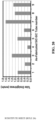
- FIG. 2B shows representative profiles of different contributions to cladding stresses for a SiC-SiC composite LWR cladding. Stresses from thermal expansion, swelling, and pressure are shown as a function of radial position through the cladding wall thickness, and are shown for the end of cycle and shutdown situations, which are more demanding than the beginning of cycle stresses. The stresses caused by the irradiation-induced swelling are the largest, and put the outside of the cladding wall thickness in compression and the inside in tension.
- the total anticipated stresses in the cladding can be estimated by summing these stress effects over the course of the fuel life (as temperature change, irradiation damage occurs, and as the reactor is started and stopped for re-fueling).
- the sum of these effects indicates that the irradiation induced swelling plays the largest contribution to the cladding stresses, and that the summed stresses are tensile on the inside of the cladding tube wall thickness, and compressive on the outside of the tube wall thickness. Therefore a significant benefit can be achieved if the monolithic layer is placed towards the outside of the cladding tube wall thickness rather than the inside of the cladding tube wall thickness, as the monolithic layer will see fewer tensile stresses and have a higher probability of survival over the course of the fuel life.
- This drives the cladding design which is described as follows.
- the cladding can be kept thin to maximize fuel loading, and a thinner cladding reduces the thermal gradient during operation. This reduced thermal gradient reduces the stresses described above.
- the dense ⁇ -SiC should be sufficiently thick to ensure fission product and fission gas retention, and the SiC-SiC composite should contain enough reinforcements to provide adequate toughness for the overall structure.
- the reinforced composite layers should comprise greater than 50% of the overall cladding thickness, and should preferably comprise greater than 70% of the cladding thickness.
- the cladding structure can include three or more layers.
- the cladding structure may include at least two composite layers and at least one monolithic layer, in a configuration where the two composite layers are inside of the monolithic layer.
- the two composite layers are different from each other, in order to serve complimentary functions.
- the composite layers may vary in the type of composite reinforcement used, the angle or orientation of that reinforcement, or the method of generating the reinforcement structure (for example, braiding, winding, etc.). The combination of these two (or more) composite layers provides improved performance beyond what could be obtained through the use of a single composite layer.
- one composite layer may be designed to provide a smoother surface, while a second composite layer may be designed to provide optimized strength.
- the first composite layer may contain smaller additives to improve the as-fabricated surface smoothness and minimize expensive post-processing machining steps while meeting surface roughness specifications.
- the second composite layer in this example may contain continuous reinforcing fiber in a specific braided structure which offers a balance of strength in the hoop and axial direction optimized for the anticipated stresses the cladding will experience during operations.
- the monolithic layer is outside these two composite layers and it is very important that the composite layer is located towards the inside or center of the cladding wall thickness to minimize the tensile stresses seen by the monolithic layer (as described above).
- the central composite layer (or layers) provides the primary mechanical strength and toughness.
- the inner composite layer provides complimentary mechanical support, and can also have a structure that offers a smoother inner surface.
- This smoother surface can improve performance in nuclear cladding applications by giving a more uniform pellet-cladding gap, which leads to a more uniform and consistent temperature distribution in the cladding and reduces temperature-dependent stresses and other failure modes.
- Minimizing roughness can also facilitate more efficient fabrication of the overall fuel rod, as the fuel pellets must be loaded into the cladding, and rough surfaces can catch on pellet edges and inhibit pellet loading operations. Due to the composite structure of this inner layer, the required surface roughness can be achieved with little or no additional machining, saving time and costs.
- the mechanical performance of composite layers tends to highly depend on the orientation of the reinforcements.
- a composite with a structure that offers the best combination of relative strengths in the axial and hoop directions may have a rougher, more textured surface and would not be the optimal composite structure to provide a smooth surface.
- a composite structure that offers a smooth surface may need smaller or carefully aligned reinforcements, which may not provide the optimal mechanical reinforcement on their own.
- the layers can also be designed to tightly fit together, reducing the wall thickness and increasing the reinforcement volume fraction in the cladding, which can be beneficial for enhancing the structural toughness. This approach can be applied to more than two composites layers, and cladding designs with two or more composite layers on the inside and center of a cladding tube to meet cladding performance requirements.
- SiC-based layers can be added as described in the present document, and an outer environmental barrier coating can also optionally be added.
- the composite layer is toughened by high aspect ratio ceramic inclusions, including ceramic fiber or whiskers, and an interphase layer deposited on the reinforcement allows for load transfer and sliding between the inclusions and the matrix.
- the inner layer is a thin composite layer fabricated with small-scale whisker reinforcement to provide a smooth inner surface.
- this layer can be composed of a thin layer reinforced with wound continuous fiber reinforcement.
- the following layer could then be composed of braided continuous fiber reinforcement with a structure designed to accommodate the anticipated stresses during operation.
- Another example would be two composite layers, both composed of braided continuous fiber, but with the braid structure or fiber angle of the braid varied, so as to provide the needed mechanical properties while at the same time achieving good fiber coverage and a relatively smooth surface.
- a monolithic outer ceramic layer is added.
- the positioning of the monolithic layer towards the outside of the structure and the thickness of this layer is carefully selected to ensure this layer remains in compression when subjected to operating stresses. By minimizing or avoiding any tensile loads on this monolithic layer, the chance of cracking can be greatly reduced, significantly improving the survival probability.
- an additional thin environmental barrier coating layer on the outside surface to protect the cladding from undesirable cladding-coolant chemical or mechanical interactions and/or to provide controlled surface roughness properties.
- This layer can be a metal (such as Cr) or ceramic (such as SiC).
- thin interphase layers can optionally be deposited between concentric layers to inhibit crack propagation between layers. These layers can be fabricated sequentially, with one layer deposited directly and with intimate contact on the previous layer. In various implementations, these interphase layers can include a ductile material, such as pyrolytic carbon or a metal.
- This cladding can be based on a range of materials, and, as a specific example, the monolithic layer can be silicon carbide, and the composite layers can be SiC-SiC composites, made of a SiC matrix reinforced using SiC fibers, whiskers, or other reinforcements.
- the constituent materials can be of materials of high purity because the presence of impurities tend to reduce performance in nuclear applications.
- the disclosed SiC composite structure can be configured in the form of a long, thin-walled tube.
- the wall thicknesses can be less than 2mm, and less than 1mm thick.
- the length of the tube is governed by the needs of the specific application.
- the cladding for a light water reactor may be 12 feet, 14 feet, or longer, and cladding for a gas cooled fast reactor may be between 8 and 9 feet long.
- the tube diameter may also be selected based on the needs of the applications, and can range, in some cases, from roughly a quarter-inch diameter up to three-quarter inch diameter or more.
- the cladding may be fabricated by building up layers from the inside-out, and in general, chemical vapor deposition of high purity silicon carbide is used as a key fabrication step for each layer.
- the disclosed SiC composite structure can also be configured into other non-tubular shapes.
- the aerospace field has a wide variety of applications that are an ideal match for the high temperature strength of SiC composite structures: nosecones, shrouds, airfoils, turbine blades and other jet engine components.
- the SiC composite structures may be fabricated in a similar manner to the tubular SiC claddings.
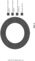
- FIG. 3 A schematic cross-section of the proposed cladding is shown in FIG. 3 .
- the illustrated cross section represents a portion of the structure.
- SiC-fiber or SiC whisker (or other small SiC additives) reinforced composite layers are used to provide toughness and mechanisms to inhibit crack propagation.
- SiC fibers and/or whiskers provide enhanced tensile strength, and fiber direction can also be optimized to balance the material performance in the axial and circumferential directions in the cladding.
- the composite layers in the cladding are positioned towards the inside and center of the cladding wall thickness.
- stoichiometric, high purity SiC fiber tows are braided into sleeves, which can be braided directly onto a mandrel or partially fabricated cladding, or can be braided separately and later positioned.
- a pyrolytic carbon or other interface layer is deposited on the fiber using chemical vapor deposition or other methods. This layer serves as an interface between the SiC fiber and the SiC matrix, and can arrest crack growth and allow for load transfer and fiber pull-out and sliding.
- High purity SiC matrix is then deposited, with a similar chemical vapor deposition process to that used for the dense ⁇ -SiC deposition.
- a slower deposition rate is used for this matrix infiltration step, and techniques such as forced flow chemical vapor infiltration can be used to reduce the fabrication time.
- Mechanical and thermal properties improve with increasing composite density, and the relative composite density can be between 70% and 90% or higher.
- the mechanisms which provide good composite behavior also depend on fiber loading, which can vary between 20% and 50% or more by volume.
- fiber loading which can vary between 20% and 50% or more by volume.
- a two-dimensional fiber orientation is used, with fibers angled between the axial and circumferential directions to optimize strength. Typical fiber angles range between ⁇ 35° and ⁇ 75° (relative to the cladding axis), and in some braid structures additional fiber reinforcement can be added aligned with eh axial direction.
- the thickness of these SiC-fiber composite layers may be selected based on the number of fibers per tow and the braiding parameters. Braiding provides improved fiber content uniformity in the composite layer compared to making multiple passes with wound fiber. If fiber is braided directly onto the partially fabricated cladding, then tension can be used to apply a desirable compressive load to the inner cladding layers. Braid architectures can be varied within the overall multi-layered structure. For example, one braided composite layer with a fiber bias angle of ⁇ 45° and another braided composite layer with a fiber bias angle of ⁇ 60°. These would constitute two distinct composite layers, and this reinforcement can be tailored to provide optimal performance.
- a wound composite layer can be formed by reinforcing fiber or tow that has been wound around the cladding or mandrel rather than being braided.
- the fiber in this layer can be wound at a desired angle (e.g., between ⁇ 35° to ⁇ 90°) relative to the clad axis compared to the braided sleeves, and one or more tows of fiber can be wound simultaneously. This provides additional fiber reinforcement in the circumferential direction, where stresses will be largest, and provides a smoother surface.
- chemical vapor infiltration will be used to densify this composite layer, and a pyrolytic carbon interphase layer or other interphase layer will be deposited between the fibers and the matrix.
- Composite layers may also be formed using smaller scale inclusions (such as SiC powder or whiskers or short lengths of SiC fibers).
- These micro- and nano-scale additives can be added in dry or slurry form, and can be densified using chemical vapor deposition, similar to the other composite types. In this way, the additives (in dry or slurry form) become the reinforcements in a distinct composite layer, and due to the small-scale of the additive, a very, very smooth composite surface can be obtained.
- this approach can also be coupled with either the braiding or winding approach, with additives impregnated into the fiber braids and winding prior to, during, or after the preforming process. In this way, these additives can be used to fill gaps and larger pores between fiber tows.
- additives can also be impregnated into fiber tows, which can subsequently be wound or braided into the cladding structure.
- the liquid component of the slurry can be evaporated or pyrolyzed during processing, leaving only small-scale reinforcing inclusions.
- the liquid phase component in the slurry can be a pre-ceramic polymer, which can be reacted to produce crystalline SiC.
- a pyrolytic carbon or other interface layer is deposited on the small-scale additives using chemical vapor deposition or other means to facilitate toughening mechanisms in the composite.
- the dense SiC layer may be stoichiometric, high purity, and 0-(cubic) phase in some implementations.
- Certain methods commonly used to produce SiC may not be suitable for making nuclear-grade SiC due to high impurity levels ( J. Nuc. Mat., vol. 371, pg. 329 (2007 )).
- nuclear-grade SiC can be deposited using a vapor phase reaction with methyltrichlorosilane, methylsilane, silane and hydrocarbon, or other suitable precursors.
- Dense ⁇ -SiC has a relatively low fracture toughness (K1C-3-5 MPa ⁇ m), and under stress, cracks could initiate at small defects or flaws and propagate through the dense SiC thickness, releasing fission gas, and potentially leading to brittle failure. This unacceptable outcome may be addressed in several ways.
- the cladding is designed to ensure stresses in the dense ⁇ -SiC due to gas pressure, swelling, thermal gradients, fuel-cladding interactions, and other operation stresses remain compressive. This is achieved through specific positioning of the monolithic layer towards the outside of the structure.
- a 35 ⁇ m layer provided sufficient thickness for the impermeable SiC layers to ensure fission product retention and pressure containment ( J. Nuc. Mat., vol. 355, pg. 150 (2006 )).
- the internal pressure is lower ( ⁇ 15MPa at end of life compared to ⁇ 40MPa for German TRISO fuel, J. Nuc. Mat., vol. 371, pg. 270 (2007 )), but the hoop stress in the cylindrical geometry is higher than stresses in spherical pressure vessels.
- the dense ⁇ -SiC layer thickness should be at least 100 ⁇ m. The maximum thickness is governed by the needs to maintain a sufficient fiber loading and to keep the cladding wall thickness thin to minimize stresses related to temperature gradients. Additional polishing of the outer SiC layer can be performed to achieve a desired surface roughness.
- the relatively low fracture toughness of dense monolithic SiC can be addressed using one additional route: using ductile layers to inhibit crack propagation.
- These layers can be pyrolytic carbon or other ductile materials (metals, etc.), and can be deposited in between successive monolithic layers or on the outside of the monolithic layer. Preferably, these layers can be deposited in multiple positions within and on the surface of the monolithic layer or layers. Layers near the inside or outside of the monolithic layer can serve to isolate the monolithic layer from micro-cracking in the composite, or from impacts or stresses on the outside, respectively. Ductile layers deposited between successive monolithic layers serve to partially isolate each monolithic layer from the others, allowing loads to transfer, but preventing cracks from propagating through. This leads to an increased overall reliability and toughness for these monolithic ceramic layers, and provides a structure which can withstand a crack through one monolithic layer without a loss of hermeticity.
- FIG. 3 The simple cross-sectional schematic shown in FIG. 3 is a representation of the most simplified version of this invention. However, there are many possible ranges which would be covered, with variations in type of composite, relative thickness of layers, and number of layers. Some additional examples are shown as follows, and it should be noted that these examples are just provided for illustrative purposes, and these examples are not comprehensive and other protected structures can exist beyond those shown here.
- FIG. 4 shows a schematic of cladding cross-section containing inner wound composite layer, middle braided composite layer, and outer monolithic layer.
- FIG. 5 shows a schematic of cladding cross-section containing multiple inner braided composite layers and an outer monolithic layer.
- the braid layers may differ in architecture (e.g. biaxial vs. triaxial), and/or fiber angle (e.g. 45° ⁇ 5° for the first layer, 50° ⁇ 5° for the second layer).
- FIG. 6 shows a schematic of cladding with wound composite inner layer, braided composite central layer, and outer monolithic layer composed of several thin monolithic layers separated by ductile layers.
- FIG. 7 shows a schematic of cladding with inner small-additive composite layer, central braided composite layer, subsequent small-additive composite layer, and outer monolithic layer with environmental barrier coating layer (EBC).
- EBC environmental barrier coating layer
- the cladding may be fabricated in successive layers, from the inside out.
- a mandrel may be used to define the inner cladding diameter at the beginning of the fabrication process, and subsequent layers are formed on top of the previous layer.
- all fiber must be stoichiometric, low-oxygen silicon carbide fiber, such as Hi-Nicalon type-S (Nippon Carbon Co., Ltd.) or Tyranno-SA (UBE Industries Ltd.), or similar.
- Reinforcing additives used in such composite structures such as nano-scale SiC whiskers or short lengths of SiC fiber, should be high-purity, stoichiometric, beta-SiC. Nominally, the SiC composite matrix and dense ⁇ -SiC layers will be deposited in-situ, using established chemical vapor phase deposition techniques.
- Various other deposition methods that can produce high purity, stoichiometric silicon carbide may also be considered, such as pre-ceramic polymers that are processed to form SiC.
- FIG. 8 shows X-ray computed tomography (XCT) reconstruction of cladding tubes fabricated with inner wound composite layer and subsequent braided composite layer. This shows that the combination of these two distinct composite layers offers significantly reduced surface roughness on the inner surface, while offering the mechanical strength advantages of a braided layer for the second composite layer. Note that in this sample, the outer monolithic layer is not shown.
- XCT X-ray computed tomography
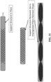
- FIG. 9A shows examples of cladding tubes with a thin, small-additive composite inner layer and a subsequent braided composite layer (901) or layers (903).
- the inner composite layer 905 is highlighted in blue, and the surrounding composite layers 903 are highlighted in green, showing the smooth surface of the inner layer, and the rougher surface of the surrounding layer.
- the inner layer provides the smooth finish, while the surrounding layer provides the optimal mechanical reinforcement.
- FIG. 9B shows a scanning electron micrograph (SEM) of a composite fracture surface obtained after mechanical testing.
- SEM scanning electron micrograph
- the SEM demonstrates an example of the toughening mechanisms that can be obtained from two distinct composite reinforcements: continuous SiC fiber 905 and dispersed small-scale SiC whisker additives 907.
- Composite toughening mechanisms, such as crack deflection, and reinforcement pull-out, can be observed from both reinforcing fibers 905 and from reinforcing small-scale SiC whiskers 907.
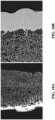
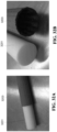
- FIG. 10A shows an example of dense monolithic ⁇ -SiC deposited over a braided SiC-SiC composite and FIG. 10B shows an example of dense monolithic ⁇ -SiC deposited over a woven SiC-SiC composite.
- FIG. 11A shows an example of thin ductile layers deposited between successive monolithic layers on the outside of the composite layer in the cladding.
- FIG. 11B shows an example of slightly thicker ductile layers deposited between successive monolithic layers on the outside of the composite layer in the cladding.
- FIG. 12 shows an example of a cladding structure with two outer monolithic layers, deposited on top of a braided composite layer, and separated by a thin, small-additive composite layer.
- exemplary embodiments were fabricated.
- chemical vapor infiltration was used to fabricate SiC-based cladding tubes at approximate LWR cladding diameters and in lengths up to three feet.
- Prototypical cladding architectures were produced including structures containing an outer monolithic SiC layer.
- Composite samples were reinforced with stoichiometric SiC fiber (Hi-Nicalon type-S fiber, NGS Advanced Fiber Co.).
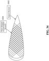
- the tube structures (tubes composed of only SiC-SiC composite and those with an outer monolith layer) were formed by placing fiber around a mandrel to define the tube inner diameter. The mandrel was later removed as part of the overall fabrication process. Details regarding exemplary methods of fabrication of SiC-based cladding tubes are discussed below in connection with FIGS. 27-36 .
- fiber orientation was varied by adjusting the number of fiber tows used and the angle relative to the tube axis, and for these examples, preforms were produced containing different ratios of fiber in the hoop and axial directions, ranging from 1.3: 1 (hoop biased) to 1:1.5 (axially biased). These fiber ratios were used for these demonstrations, but do not represent a limit on the ranges of fiber orientations covered in this invention. These variations can be used to demonstrate the benefit of this invention, by showing the ability to control the mechanical properties of the cladding as a function of the structures of the composite layers.
- a pyrolytic carbon interphase coating of ⁇ 150nm was deposited via the chemical vapor decomposition of methane or acetylene, and the matrix was then deposited and densified through the chemical vapor infiltration of methyltrichlorosilane to a final relative density of approximately 80%.
- the embodiments described herein should not be viewed as a limit to the processing and structure variations.
- the composite densification step represented the final processing step for those tubes composed of all composite and those containing a SiC inner monolith. For those tubes containing an outer monolith, additional SiC was deposited to form a dense outer SiC coating.
- final tube wall thicknesses varied depending on the structure, and ranged from 1.2mm to 2.1mm.
- Tubes composed only of SiC-SiC composite had wall thicknesses between 1.2mm and 1.4mm while tubes with an inner monolith were slightly thicker (1.3mm to 1.5mm), and tubes with an outer monolithic layer were 1.9mm to 2.1mm thick.
- That monolithic layer made up approximately 30% of the wall thickness.
- the claddings were evaluated in terms of mechanical performance, hermeticity, and geometric and dimensional tolerances.
- Mechanical properties of SiC-based tubes can be evaluated using several methods. Hoop strength was measured using C-ring testing and expanding plug testing, while axial strength was measured using monotonic axial tensile testing.
- C-Ring testing was carried out following similar guidelines established for monolithic ceramics in ASTM C1323 and described in Jacobsen et al. Samples rings were cut to 2-3 mm thicknesses using an Accutom-50 diamond saw and subsequently polished using diamond grit. While most testing was performed on material sized for LWR cladding applications ( ⁇ 7.5mm inner diameter), some additional samples with a larger diameter were also measured ( ⁇ 19mm inner diameter, fabricated using very similar fiber architectures to the LWR-size material and densified using the same process). These larger diameter tubes were produced to show the applicability of these structures for nuclear fuel cladding designs larger than LWR cladding dimensions. A C-ring gap of 4 mm was used for LWR sized material and 7.5 mm for the larger diameter material.
- Load was applied to the specimens using an Instron 5982 Universal Mechanical Tester at a crosshead speed of 2 mm/min. For each reported data point, a minimum of 5 specimens was tested, with 10 specimens being typical. Load was converted to stress using curved beam theory.
- Expanding Plug testing was performed following the procedures established in the literature. Specimens were cut and polished to approximately 25 mm in length, and a 12-15 mm polyurethane plug of 95 durometer hardness was used. Crosshead speed was set to 1.5 mm/min. Strain was monitored during testing through strain gauges with 2.5-3 mm gauge length (Omega). A minimum of 5 tests were performed for each sample, and stress at the tube ID and OD was calculated using Lamé's equation.
- Axial tensile testing was performed using the procedure described in ASTM C1773.
- a passive gripping fixture was utilized where the tube was epoxied at both the ID and OD (United Resin Corps Tuff Bond epoxy).
- Total sample length was 100-120 mm, with a gauge section of 50 mm.
- a U-Joint was utilized to help ensure proper alignment as measured through a set of 4 or 8 strain gauges with 3-4 mm gauge length mounted in 90 degree intervals.
- Crosshead speed was set to 2 mm/min.
- the reported data represents an average of a minimum of 3 tests.
- Thermal diffusivity was measured using a NETZSCH LFA 427 laser flash analyzer, following the approach introduced by Parker et al., and with modifications for sample geometry according to Zhang et al. Both flat and curved samples were measured, and curved specimens were cut from the sides of SiC-SiC tubes. The sample size was kept constant at 10 mm x 10 mm to fit into the specimen holder for the analyzer. Thermal diffusivity was measured in the through-thickness direction at 25°C, 300°C, and 800°C, and three measurements were taken at each temperature.
- SiC-SiC tubes Permeability of SiC-SiC tubes was assessed using a mass spectrometer leak detector (Agilent VS MD30) and with consideration of guidelines from ASTM E432-91 (2011).
- the leak detector was assembled together with a roughing pump, custom chamber, helium source, and pressure gauges. Specimens to be tested were held in the chamber between a high pressure and a low pressure region, and this assembly could be positioned inside a tube furnace to facilitate permeability testing at elevated temperatures.
- a pressure differential of 1atm was applied across the sample during a test, and then the leak rate was monitored as helium was detected permeating through the sample and until the leak rate had achieved a steady state.
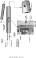
- FIG. 13 One exemplary test configuration is shown in FIG. 13 . This equipment could be used to measure leak rates through both open ended SiC-SiC tubes, and tubes which had one end sealed with a SiC endplug, joined using a SiC-based joint.
- profilometers were made using a stylus surface profilometer (Dektak 6M with 2.5 ⁇ m radius diamond tip) to compare with the roughness values extracted from the XCT volumes.
- the profilometer scan length was between 2mm a 7mm, with a vertical height range of 254 ⁇ m, and a vertical step resolution of 4nm. All profilometer roughness scans were made in the axial direction.
- CMM Coordinate Measuring Machine
- SPI 13-599-6 digital height gauge
- Infiltration uniformity may be assessed by measuring the thickness of CVI SiC deposition on the outside of the SiC-SiC tube walls.
- This outer SiC layer forms during densification, and its thickness is affected by the composite structure, infiltration conditions, and infiltration efficiency. Variations in this outer CVI SiC layer can therefore serve as an approximate indication of the uniformity of the underlying composite. Longer tubes were cross sectioned at 10cm intervals, mounted and polished, and thickness was measured using scanning electron microscopy (Phenom X SEM).
- Performance attributes for silicon carbide-based nuclear fuel cladding (including cladding designed for accident tolerant fuel for current LWRs and cladding designed for other advanced reactor concepts must be defined and demonstrated for normal operation, design basis accidents, and beyond design basis accidents, and cladding fabrication must be feasible at a very large production scale.
- a very thorough assessment of these requirements and performance criteria has been published by Bragg-Sitton et al., and some of the key cladding metrics include mechanical strength, thermal behavior, impermeability, and dimensional control.
- dimensional requirements will likely be similar to current Zircaloy cladding tube specifications, which include ⁇ 0.8-1.3 ⁇ m surface roughness requirements ⁇ 25 ⁇ m ovality requirements, and 0.25mm per 300mm length straightness requirements.
- an impermeable monolithic SiC layer can be deposited using chemical vapor deposition on the outside of a composite tube, resulting in an outer-monolith design, as described in this patent document.
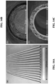
- FIGS. 14A-C Examples of the tubes and structures fabricated are shown in FIGS. 14A-C.
- FIG. 14A shows examples of ⁇ 0.9 m long SiC-SiC tubes fabricated.
- FIG. 14B shows the cross-section of a tube structure with an outer monolithic SiC coating.
- the first architecture had a slightly higher ratio of fiber reinforcement the axial direction than the hoop direction (1,5:1) while the second architecture was biased in the hoop direction (1.3: 1; for comparison, an architecture with fibers oriented at ⁇ 45° would be balanced with a 1:1 hoop:axial reinforcement ratio).
- C-ring testing was used to measure hoop strength and monotonic tensile testing was used to measure axial strength, and the engineering ultimate tensile strengths for the two different fiber architectures are reported in Table 1. This shows the wide range of control which can be achieved over the mechanical properties based on the composite structure.
- FIG. 15A The stress versus displacement plots for representative c-ring tests are shown in FIG. 15A .
- C-ring testing is most suitably compared to planar flexure testing, it has been demonstrated that for relatively uniform composites c-ring testing gives a good approximation of hoop stress.
- the strengths and moduli observed in this work are similar to those reported previously for both SiC-SiC panels and tubes, although differences in fiber architectures between reports mean that comparisons will only be approximate. For both fiber architectures, similar displacement at failure is observed.
- the hoop biased composite shows a more than 50% increase in ultimate tensile hoop strength and a better ability to carry residual load beyond the UTS.
- FIG. 15B shows representative stress vs. strain plots for the uniaxial tensile tests of these specimens.
- axially biased fiber architecture a much higher axial UTS is observed. This is consistent with the C-ring test results where additional reinforcement in the loading direction leads to higher strength. This result is expected and consistent with reports in the literature where polymer matrix composite tubes with varying fiber orientations showed a trend of increasing failure load correlating with increasing fiber aligned in the loading direction.
- additional strain at failure and a lower modulus is observed, which could be due to differences in density and porosity distribution of the composites. Again, this shows the importance of the composite architecture on the performance, and the benefit which can be achieved by using two or more, distinct and different composite layers to improve performance.
- all specimens characterized for each strength test method had the same length, chosen with respect to the technique being used to make the measurement.
- Katoh et al. report that composites tested with a loading direction off-axis to the fiber reinforcement direction exhibit a specimen width effect on strength, particularly when the specimen width is comparable to the fiber reinforcement unit cell width (with decreasing strength values observed with decreasing specimen width).
- expanding plug and axial tension tests use specimens that include the complete tube diameter and have lengths many times the unit cell dimension, so sample size is no issue.
- the C-ring tests use a shorter length of tube (2-3mm), however Jacobsen et al. reported good agreement between hoop strength values measured on larger expanding plug test specimens and C-ring test specimens of the same size as used in this current work.
- Jacobsen et al. reported good agreement between hoop strength values measured on larger expanding plug test specimens and C-ring test specimens of the same size as used in this current work.
- the specimen sizes used in this work are large enough to provide representative measurements of the properties for
- FIG. 15C shows results from additional mechanical testing performed on a composite reinforced with only small-scale additives.
- These SiC structures (such as SiC whiskers), are much smaller than the continuous SiC fibers used in the braided fiber or wound fiber types of SiC-SiC composite.
- These additives provide some reinforcement.
- a structure containing braided fiber or wound fiber reinforcement is preferred to provide higher strengths, and the ability to tailor the mechanical properties between the hoop and axial direction to best meet performance needs.
- these small additive composites provide other benefits, such as offering much smoother as-fabricated surface roughness compared to continuous fiber reinforcements.
- the use of multiple, distinct composite layers leverages the advantageous properties of each type of composite layer and allows the creation of a structure that combines the best attributes of each.
- this invention also utilizes a multi-layered structure in which a monolithic layer of SiC is placed either on the outside or inside of the composite, or both.
- the monolithic SiC offers improved oxidation resistance compared to SiC-SiC composites, and, provided it remains uncracked, can provide hermeticity, while the composite layer provides increased strength and toughness to the cladding.
- fission gas must be contained throughout the fuel life, it is important for the monolithic layer to remain intact through normal operating conditions.
- this monolithic layer is optimally positioned on the outside of the cladding to best accommodate expected stresses during reactor operation.
- the thermal conductivity of a sample can be determined as a function of the sample's specific heat, density, and thermal diffusivity. Specific heat and density measurement can be made without needing to account for the sample geometry.
- the thermal diffusivity measurement is typically obtained from a flat specimen using the laser flash method, where a pulsed laser delivers energy to one side of a sample and the temperature rise on the opposite side of the sample is monitored as a function of time.
- the thermal diffusivity is a function of the sample thickness and the time-temperature profile, specifically the time required for the temperature to reach half the eventual maximum value. This approach assumes a flat sample and 1 dimensional heat transfer, and therefore cannot be directly used to measure thermal diffusivity in curved samples, where heat transfer in two dimensions occurs.
- a geometric factor can be determined as a function of sample curvature and then used as a correction to the measured value to obtain the actual material diffusivity value.
- thermal diffusivity and conductivity vary as a function of measurement direction, and are typically higher in the in-plane direction compared to the through thickness direction for SiC-SiC composites, as the fibers can conduct heat and the porosity distribution is different.
- high thermal diffusivity, and a corresponding high thermal conductivity are important to ensure heat removal from the fuel and reduce stresses in the cladding caused by thermal gradients.
- Permeability is a critical performance metric for SiC-based cladding, as hermetic containment of fission gas throughout the fuel life is challenging due to the occurrence of matrix cracking at stresses beyond the proportional limit strength and residual porosity in SiC-SiC composites.
- Permeability of monolithic silicon carbide is extremely low, and a versatile fixture was used to hold specimens and prevent leakage of helium while facilitating measurement of very small leak rates through the sample. The fixture assembly was verified to give consistent performance at elevated temperatures, allowing testing at 300°C. To ensure accurate results, a calibrated leak standard and null and control samples were used to differentiate between permeation through the seal (between the sample and the fixture), and permeation through the sample itself. In addition, excessive tube surface roughness interfered with the ability to obtain a leak-tight seal on the sample surface, so care had to be taken in sample preparation.
- the leak rate requirements were allocated based on the maximum acceptable leak rate for current pressurized water reactor (PWR) fuel cladding, which was taken as 10 -6 atm-cc/s with 1.7 MPa helium pressure at room temperature. This value will vary for cladding used in other reactor types that is based on this invention, and the results will show that this design is capable of meeting leak rate requirements significantly more strict than the requirements given here. From this value, leak rate requirements were extrapolated for smaller specimens tested at various temperatures and pressures.
- a suitable SiC-based material used in a fuel cladding application should meet leak rate requirements through the tube walls, and the entire cladding structure, including material used to seal the ends, should also meet the requirements.
- a silicon carbide based joining method can be used to seal one end of SiC-SiC composite tubes with a monolithic SiC endplug.
- These joints include high-purity cubic SiC, and achieve room temperature shear strengths of ⁇ 80 MPa, meeting requirements for containment of expected end-of-life LWR cladding pressure, as well as anticipated cladding requirements for other reactor fuel rod designs.
- the tubes used were SiC-SiC tubes coated with an outer monolithic SiC layer, and, both open ended SiC-based tubes as well as tubes which had one end sealed using a SiC endplug and SiC joint were tested. This helium leak measurement approach is versatile and could be adapted for different SiC component geometries beyond tubes through the use of a modified fixture and sealing method.
- the cladding structure will undergo stresses and loading conditions during the fuel life, including internal pressurization due to fission gas build-up, thermal cycles, and mechanical stress cycles during power ramps or shutdowns for fueling.
- the cladding must maintain hermeticity throughout these conditions, while being simultaneously being subjected to neutron irradiation.
- FIG. 17 Also plotted in FIG. 17 is a nominal leak rate requirement, as well as a typical leak rate measured for a tube composed of only a single composite layer (without an external monolithic SiC layer). This shows the challenge in achieving the needed hermeticity for a composite-only structure, and clearly shows the substantial improvement which is gained by coupling a monolithic layer with multiple inner composite layers to improve the impermeability of the structure.
- the as-fabricated tube shows significant surface texture resulting from the underlying fiber tow architecture, as seen in a representative photo of starting fiber structure prior to infiltration, as shown in FIG. 19A . Multiple scans were obtained for each approach, and average roughness for the overall tube can be obtained. Representative surface profiles from the stylus profilometer are shown in FIG. 19B and are qualitatively similar.
- Roughness values obtained from the profilometer are given in Table 2.
- the height of the individual reinforcing SiC fiber tows is in the range of ⁇ 200 ⁇ m - 300 ⁇ m, and the fiber architecture and regions where tows overlap contribute to the surface undulations in the as-fabricated tube. Therefore, it is an expected result that the peak-valley roughness measurement obtained is very similar to the thickness of the individual fiber tows.
- Table 2 Roughness values for the outer surface of an as-fabricated SiC-SiC tube taken from a 7 mm long axial line profile.
- Roughness Profilometer result R average 32.7 ⁇ m
- the large peak-valley roughness (as well as average and rms roughness values) in the as-fabricated tube is not expected to be sufficient for a nuclear fuel cladding application. Excessive roughness on the cladding inner surface will lead to variations in the gap between the fuel and cladding and can result in non-uniform temperature gradients, causing additional stresses in the cladding. In addition, although high surface roughness on the outside surface of the cladding may provide some benefits to heat transfer due to turbulent mixing, this roughness will increase the coolant pressure drop through the core.
- the use of two or more distinct composite layers can address this problem, by combining composite layers optimized for a smooth surface and composite layers optimized for strength.
- cladding tubes with controllable roughness on both the inner and outer surfaces.
- Several methods can be used to achieve controlled surface roughness, such as polishing or grinding, or through the use of composite layers which can provide an improved surface smoothness compared to the continues fiber reinforced composites shown in FIG.19A .
- a tube which has thin composite layers containing small reinforcing additives on the inside and outside of a braided SiC-SiC composite layer was examined, as shown in FIG. 19B and FIG. 19C .
- Average, root-mean-square, and peak-valley roughness are tabulated in Table 3, and represent a significant ( ⁇ 5-10x) reduction in roughness for this small additive composite layer tube compared to the braided fiber SiC-SiC tube.
- Representative surface profile scans for this small additive composite surface and the braided fiber composite surface are shown in FIG. 19D . While roughness specifications for SiC-based fuel cladding has not yet been defined, these values are close to the current specification for Zircaloy cladding tubes, and further improvement could be obtained through additional refinements to processing methods. Roughness values for the inner and outer surfaces are comparable. Standard deviations were obtained from roughness values from 2mm long line scans taken from six different areas on the tube sample.
- Straightness and cylindricity are very important for fuel cladding applications, as deviations from straightness can lead to non-uniform spacing between tubes in a tightly packed fuel assembly, causing variations in heat transfer, increases stresses, and potential bowing.
- straightness measurements assess the maximum deviation of the tube surface from a straight reference line aligned along the tube axial direction. Although only straightness and roundness (or ovality) may be required specifications for a cladding tube, cylindricity measurements combine an assessment of both the tube straightness and the tube roundness into a single measurement, as deviations from both straightness and circularity contribute to the overall cylindricity value. Cylindricity measurements may be easily obtained through analysis of reconstructed XCT volumes, and this provides a single value to assess the tube geometry.
- Cylindricity was measured by fitting cylinders to the exterior of the measured tube, and this was performed for each of the four ⁇ 25cm long XCT volumes, as well as the stitched full length tube.
- the fitting process involved a user manually selecting a large number of randomly chosen points on the surface to be fit (either the inner or outer surface of the tube; for the following results the outer surface was used). 5000 evenly spaced points were automatically fit to the surface of the tube to envelope the manually selected points and a perfect cylinder was fit to these automatically selected points using a Gaussian least squared fit method. These points were used to obtain the cylinder diameter, and the cylindricity was also determined by finding the maximum inscribed and minimum circumscribed circles based on the fit to the cylinder. The scan size selected for these measurements gave a resolution for the cylindricity measurements of 127 ⁇ m, and this represented a balance between the scan resolution and number of scans necessary to encompass the full tube length.
- Cylindricity results were first obtained for shorter volume sections (each approximately 25cm long). The cylindricity for these volumes averaged 399 ⁇ m (standard deviation of 49 ⁇ m), with an average outer radius of 4.56mm (standard deviation of 0.019mm). The stitched and merged volume representing the entire 0.9m long tube was then analyzed, and the fit process (initiated by user-selected surface points) was repeated eight times. Average tube outer radius for the entire length was almost identical to the average radius for the individual sections at 4.57mm (compared to 4.56mm), and there was essentially no variation between each of the eight individual fits that were analyzed (standard deviation of the radius for these eight different fits was 0.001mm).
- the average cylindricity for the fit of the merged volume was 774 ⁇ m, with a standard deviation of 30 ⁇ m between the different fits. This indicated that while there is a manual aspect to the fitting process (the user selection of surface points which forms the basis for the fit), the potential error introduced by this selection is small (standard deviation is only ⁇ 4% of the average cylindricity value).
- a coordinate measuring machine (CMM) and a vertical height gauge were also used to evaluate the cylindricity of these tubes, as a comparison to the XCT-derived values.
- This measuring approach offers improved resolution compared to the XCT scans (12.7 ⁇ m in the X, Y, and Z directions), and can measure the entire 0.9m length of the tube at once.
- the CMM approach is limited in that location measurements are taken individually, and as a consequence it is not practical to sample thousands of surface points, which the XCT approach is able to provide. This CMM limitation may introduce some sampling error, and potentially under-represent the cylindricity.
- the cylindricity for a cladding tube will depend on the straightness obtained in the underlying composite, and would be defined near the start of processing (absent any mechanical grinding or polishing steps at the end of fabrication). The cylindricity value reported above therefore gives a good approximation of the straightness that could be currently obtained for these structures.
- a vertical height gauge was used to find the highest point along the length of a tube while the tube ends rested on a flat granite surface. While this vertical height gauge method provided a quick measurement, the practical accuracy of this approach relied on a visual assessment to ensure the highest point on the tube was being measured. As such, while the resolution of the vertical height gauge was 10 ⁇ m, the accuracy of this measurement method was subject to more user error than both the XCT and CMM cylindricity measurement methods.
- this method only measured the highest point on the tube, it provides a straightness measurement, rather than a cylindricity measurement (cylindricity would incorporate both straightness and roundness assessments, and with only the highest point sampled, the vertical height gauge does not measure the roundness contribution to the cylindricity).
- these height gauge measurement were used to evaluate the straightness distribution across a range of tubes produced using nominally the same fabrication method. All tubes were ⁇ 0.9m long, and across the nine tubes, the average straightness was 863 ⁇ m, and the standard deviation between all samples was 453 ⁇ m. This set of measurements is shown in FIG. 20 .
- the current cladding straightness requirement is 0.25mm per 300mm length (which translates to 0.833mm/m), and the tube measured using the XCT and CMM methods, and approximately half the tubes measured by the height gauge method meet the specification (three of the tubes measured using the height gauge exceed the requirement, and two are within 3%).
- repeatability is expected to improve and result in a higher yield of tubes meeting this specification, and this shows that the cladding design described in this invention can meet cladding straightness requirements.
- Fiber structures and orientations can be maintained with good consistency for long tubes; however, the infiltration of these fibers can vary as a function of length during the chemical vapor infiltration process.
- the completeness of infiltration is a function of the temperature, pressure, and local precursor concentrations during infiltration, and all these parameters, as well as byproduct concentrations, can vary throughout the infiltration chamber, both spatially and temporally.
- a deposition gradient develops from the outside of the composite to the center, and this will result in the gradual formation of a dense SiC layer on the outer surface of the composite.
- the uniformity of the infiltration can be assessed by measuring properties or porosity as a function of position along the length of the tube, or as a coarse approximation, the thickness of the outer SiC layer can be used as a gauge of the uniformity. This approximation assumes that if the deposition of SiC on the outer composite surface is uniform, then the interior infiltration will likely be similar. While not as accurate as direct comparison of mechanical and thermal performance at different points along the tube length, or density measurements, the variation in the SiC coating thickness as a function of length can provide important feedback on the uniformity of the infiltration process.
- Measurements of uniformity along the length of a representative tube were performed using two approaches. First, XCT scans were taken at approximately 10cm intervals along the length, starting at one end and continuing to the center of the tube. A representative volume of the tube was analyzed at each interval and total material volume as well as total internal pore volume was measured. Due to the resolution of the XCT scans used, extremely small pores may not be resolved, and as a consequence, these values may slightly underestimate the actual total sample porosity. However, a significant variation in this underestimation as a function of position is not expected, and these XCT scans should give a good indication of uniformity. The porosity fraction was calculated from these measurements, and is plotted as a function of position along the tube length in FIG. 21 .
- the second approach utilized the overcoat thickness approximation, and measurements of overcoat and variations in thickness (normalized to the average thickness) were obtained and are also shown in FIG. 21 .
- This data only represents half the distance along the tube length (from one end to the center); however through periodic rotation of the tube during fabrication it is expected that any thickness variation is symmetric from each tube end.
- These initial results show that the porosity ranges between 5% and 8% along the tube length, and the coating thickness variation is 5% or less.
- no clear trend of varying porosity or overcoat thickness is observed as a function of position.
- a complete assessment of the density, mechanical, and thermal properties along the tube length would provide a more complete data set, however, these results suggest that good tube axial uniformity can be achieved for this cladding design.
- Those tubes containing an inner monolithic layer incorporated a thin-walled ( ⁇ 450um wall thickness) extruded and sintered SiC Hexoloy tube (St. Gobain Ceramic Materials).
- SiC Hexoloy Compared to CVD SiC, Hexoloy has similar unirradiated material properties but contains sintering aids and has slightly lower density and purity. Reinforcing fiber was then formed around this inner monolith as a second layer.
- the tube structures (tubes composed of only SiC-SiC composite and those with an inner composite layer) were formed by placing fiber around a mandrel to define the tube inner diameter.
- FIG. 14C shows the cross-section of a tube structure with an inner monolithic SiC layer.
- the pore geometry may also show a directional dependence.
- the void shape and alignment is influenced by the fiber architecture, and this may also contribute to the observed variations in hoop and axial strengths. Another contributing factor could be the potential for more complicated stress states to occur during gripping and loading and contribute to initiating failure in the specimen.
- small misalignments can introduce bending moments during loading, whereas contact points on C-ring specimens are far away from the point of failure.
- measured bending for the axial tensile test was typically below 5%.
- a more detailed study of effects of both fabrication and mechanical testing parameters on the measured SiC-SiC composite properties is needed, to resolve the discrepancy between model predictions and measurements. Nevertheless, the model calculations provide a relative guide for assessing architectures.
- Multi-layered tubes have been tested with either an inner or outer monolithic layer to investigate the effects of this multi-layered structure on mechanical performance. During mechanical testing, this multi-layered structure remained intact, and delamination between layers was not observed. Additional tubes composed solely of SiC-SiC composite with the same fiber architecture but lacking a monolithic SiC layer were processed in identical conditions and tested for comparative purposes. Fully monolithic tubes were not tested in this work, but as a reference, CVD SiC has a modulus of ⁇ 460 GPa and strength ranging from 200 MPa to 500 MPa, and sintered Hexoloy SiC has a reported flexural strength of 280 MPa and modulus of 420 MPa at room temperature.
- the reinforcing fiber architecture used is the same as the axial biased architecture shown in Table 1.
- the outside monolith and their corresponding all-composite tubes were larger than typical LWR cladding diameters ( ⁇ 19mm inner diameter); however, the fabrication process for these tubes was essentially identical to that for the smaller tubes, the fiber structure was representative, and similar results would be expected for an LWR-sized tube.
- the fiber architecture for the outer monolith and corresponding all-composite structures was hoop-biased. Due to the differences in reinforcing fiber architecture, comparisons between the strength values of the overall inner and outer monolith structures cannot be made; in this work these strength values should only be compared with their corresponding all-composite tube samples.
- both C-ring data and expanding plug data are provided due to the non-uniformity of the tube, which can cause greater deviations from hoop UTS in the c-ring test.
- stresses at both the OD and ID are calculated and reported, but this particular calculation assumes a uniform material (rather than multi-layered).
- the differences in elastic modulus and Poison's ratio between composite and monolithic cause different stress profiles between the layers and as such the reported values should be treated as approximations only.
- actual stresses in the monolithic layer would be higher than those in the composite layer, due to the higher modulus of the monolith. More detailed FEM analysis would be needed to provide a more accurate calculation of the stress distribution through these layered cladding structures.
- the UTS as measured by C-ring testing is slightly lower than the corresponding composite only UTS.
- the C-ring test puts the OD of the composite in tension and the ID in compression and as such it is both expected and experimentally observed that the stress-displacement behavior for the inner monolith specimen is very similar to the composite only, as the tensile stress is being primarily applied at the composite layer in both cases. While the overall shape and UTS are very similar, a higher displacement at UTS is observed on average for the all composite specimen. This suggests that the addition of the monolith causes some loss of toughness in the specimens due to reduced fiber fraction, showing that this inner monolith configuration is not an ideal location for the monolithic layer.
- the UTS is closer to the corresponding composite only specimen suggesting that the application of the outside monolith has little effect on the composite layer itself and once the monolith layer is breached it behaves similarly to a composite only specimen.
- This observation is supported by C-ring testing seen in FIG. 22B .
- For the outside monolith specimen an initial linear elastic region is observed as the monolith layer is loaded to failure. Once the monolith layer has failed the load redistributes onto the composite and the stress-displacement behavior becomes very similar to that observed for the composite only specimen.
- FIG. 23A and FIG. 23B Of particular interest in these plots is the shape of the stress strain plot at, and just following, the PLS.
- the PLS can be determined at both the outer and inner surfaces of the tube (these are listed in Table 5), and despite the dissimilarity in PLS values seen in the plots due to the difference in location of the monolith (inner versus outer), in both cases the monolith fails at approximately 130-140 MPa. Once the monolith fails, a rapid redistribution of the strain in the system takes place due to a significant reduction in the ability of the monolith to carry stress/strain.
- Recognizable features in adjacent scan volumes that can be oriented and merged can be used to assist in the alignment process,.
- the use of appropriate alignment features may be particularly important when the volumes to be merged have similar, repeating features which cannot be easily distinguished between volumes.
- small additional portions of SiC-SiC tubes were attached to the sides of the longer tube being scanned at three intervals along the length. The exact nature of these additional alignment aids is not critical, as long as they are sized so that they have features which can easily be oriented between scans, can be fully included in adjacent scans, and have similar densities to the SiC-SiC tubes being scanned so as to not cause contrast issues in the XCT.
- FIG. 25A The configuration of one of these alignment aids relative to the SiC-SiC tube is shown in FIG. 25A , along with the four individual scanned volumes shown in FIG. 25B and the full stitched and reconstructed 0.9m long SiC-SiC tube as shown in FIG. 25C .
- Roundness was measured by fitting circles to either the inner or outer diameter of the XCT tube volume. Each fit circle utilized 5000 evenly spaced points and a Gaussian least squares method to determine the circle diameter. The roundness was then determined using the maximum inscribed and minimum circumscribed circles based on the locations of the 5000 points fit to the circle ( FIG. 26A ). This approach was used to measure roundness (and corresponding tube radii values) at 11 evenly spaced points along the axis of the stitched XCT 3D reconstruction of the entire 0.9m tube. The average outer radius based on these 11 measurements was 4.56mm (standard deviation of 0.02mm), and roundness was 242 ⁇ m (standard deviation of 22 ⁇ m). Roundness values and tube radius values along the tube length are plotted in FIG. 26B .
- the roundness values represent a significant deviation from circularity and exceed the roundness specification of ⁇ 25 ⁇ m; however, this is a consequence of the large surface roughness of the as-fabricated tubes, which have not undergone additional processing steps to reduce roughness. Since the roundness measurement is a function of the highest and lowest points along a cylindrical cross section, the unevenness caused by the underlying fiber tow structure leads to the large measured roundness values. For tubes such as those measured in this work with high roughness, the contributions of ovality and roughness to the overall roundness value cannot be isolated as shown in FIG. 26C and FIG. 26D .
- the increase in the cylindricity obtained from the individual and stitched XCT reconstructions could arise from two different sources.
- One cause of this would be an actual increase in the straightness deviation for the longer tube compared to the 25cm individual segments scans. If there was a larger straightness deviation in the overall length of tube that was being missed by analyzing individual 25cm long scans, then it would be expected that the straightness value would increase with increasing tube length, and correspondingly, decrease with tube length being analyzed was decreased.
- the straightness would instead be strongly influenced by the straightness of the underlying monolithic tube.
- the cylindricity of an extruded, ⁇ 0.9m long, thin-walled ( ⁇ 400-500 ⁇ m wall thickness) Hexoloy tube was measured using the CMM. This was the same material used in the inner monolith structures shown in FIG. 14C . The cylindricity for this part was 267 ⁇ m, or slightly more than half that of the as-fabricated SiC-SiC tube.
- this Hexoloy tube As the surface roughness of this Hexoloy tube is far smoother than that of the as-fabricated composite tube, there is a significant roughness contribution ( ⁇ 200 ⁇ m, see Table 1) to the cylindricity in the all composite tube that is absent in the Hexoloy cylindricity.
- the roughness caused by the fiber architecture would still be present in the overlaying composite layer, so the 267 ⁇ m cylindricity measured for the Hexoloy tube should represent a best-case cylindricity for a tube with an inner monolith structure, and the final cylindricity may be comparable to that of the all-composite or outer monolith tube.
- Fiber architecture of SiC-SiC composites had a significant impact on the relative hoop and axial strengths of the tubes tested in this work. Results support the view that careful design of tube fiber structure will allow for control and balancing of the resulting hoop and axial strengths to meet operational requirements. Hoop strengths were also measured for multi-layered tube structures, and these specimens had strengths similar to corresponding all-composite samples.
- SiC-based tube structures with an outer monolithic layer were verified using a helium leak detector.
- Prototypical tube structures, including open-ended tubes and those composed of a tube sealed on one end by an endcap and a SiC-based joint were subjected to mechanical and thermal loading. These structures composed of a tube sealed with an endcap using a SiC-based joint demonstrated durability and the ability to withstand a range of stresses while still maintaining impermeability.
- x-ray computed tomography can provide a versatile means to measure a wide range of dimensional tolerances. Very large parts, which exceed the machine size limit for a single scan, must be scanned in multiple segments, and these can be recombined into a single volume for analysis. Roughness can be measured using a stylus profilometry for as-fabricated composite tubes (showing considerable texture from the underlying fiber structure).
- a composite layer incorporating small-scale SiC whiskers and other additives provided significantly improved surface smoothness, showing the benefits of combining multiple, distinct composite layers.
- Tube cylindricity and straightness were also assessed. Three approaches were used to measure tube cylindricity, and these values, which include contributions from both tube straightness and surface roughness, ranged from 0.5mm to 1.0mm deviation per meter length.
- the measured roughness values for the smoother SiC-SiC tube were close to the current specification for Zircaloy cladding tubes. The majority of the long ( ⁇ 0.9m) tubes measured meet the current straightness requirement.
- the multi-layer SiC composite structures disclosed herein can be manufactured using various methods.
- graphite can be used as a mandrel material capable of withstanding the harsh conditions of CVD or CVI to complete the densification process for the fabrication of the SiC composite structures.
- the mandrel removal step after the densification completes usually involves burning or machining away the graphite material because the SiC CMC can become mechanically interconnected with graphite.
- This patent document further describes techniques and methods that can be used for fabricating SiC composite structures into complex shapes without a graphite mandrel during matrix processing.
- Fabrication of the disclosed SiC composite structures can be performed using a fiber preform that is supported by a binder or additives.
- a fiber preform When a fiber preform is unsupported and does not contain a binder or additives, it relaxes into a natural resting position that has minimal stresses.
- preforms that are pre-impregnated with additives maintain their shape during CVD/CVI because an additive scaffolding supports the fibers. The fibers and additives would then remain after the binder within the slurry decomposes.
- This scaffolding acts as an inter-fiber support to keep fibers from returning to their natural resting position long enough for the coating gasses to form a rigid monolithic support structure.
- the amount of additive loading to make a supported preform can depend on the geometry of the SiC matrix. For example a thin single-layer braided sleeve with a high aspect ratio of length to diameter may need more additive support than a thick multiple-layer braided sleeve with a low aspect ratio.
- One of design considerations is the amount and direction of force being applied to the preform. For example, a fiber sheet pulled over a sharp angle will require more support around the angle than a fiber sheet pulled over a long radius curve.
- a slurry comprising additives, a binder and a solvent, can be used to facilitate manufacturing of such supported preform.
- slurry without additives can also be used to ease the handling of the preform.
- FIG. 27 shows an exemplary scheme diagram of a support structure 2702 and a fiber 2704 when they are separated before the fabrication process for producing a composite fiber preform.
- the fiber 2704 is placed on the outside surface the support structure 2702, e.g., being wrapped around the support structure.
- the fiber 2704 can also be placed inside the support structure 2702.
- the dimensions of the support structure 2702 defines the final dimensions of the part to be made.
- the placement of the fiber 2702 defines the final geometry of the part to be made.
- the fiber 2704 is wrapped around the support structure 2702 to form a preform structure outside the support structure 2702. The lower image in FIG.
- a suitable slurry is applied to the preform structure.
- the desired preform geometry as currently formed by wrapping the fiber 2704 around the support structure 2702 remains undisturbed after the slurry is applied.
- the slurry can be applied with one of various suitable methods, including, e.g., brushing, spraying, immersion, or by warm pressing.
- FIG. 29A shows, for example, a slurry is applied by brushing the slurry over the fiber wrapped support structure 2702.
- FIG. 29B shows that a slurry can be applied by submerging the fiber wrapped support structure 2702 in a slurry bath.
- the slurry application can be completed with a support structure in place that will define the final geometry.
- FIG. 30 shows the fiber-wrapped support structure before (2702) and after (3004) slurry coating is applied.
- the support structure 2702 and any other external restraints are then removed (by sliding, pushing, melting, etc.) before matrix densification takes place, as shown in FIG. 31 .
- the slurry used in the above mentioned process may include, in some implementations, additives, a binder and a solvent.
- the additives used can be powders, whiskers, fibers, granules or any combination thereof.
- the particle size is typically sub-mm and the loading fraction of the slurry solution is typically 0-75% additive.
- the binder portion of the slurry comprises a thermo-plastic polymer that deteriorates at temperatures below that of the matrix densification process and does not thermally expand during burnout.
- the binder must be a solid at the room temperature and soluble in a cleanly evaporating solvent, such as acetone, methyl ethyl ketone, and ethanol.
- the viscosity of slurry mixtures can vary greatly based on the additive to binder ratio as well as the additive and binder to solvent ratio. The slurry viscosity should be tailored to the application method being used with the added consideration that multiple applications are possible.
- the fibers used can be of various diameters, lengths, aspect ratios, cross-sectional geometries, and materials.
- the fibers can be arranged in any way that achieves the desired final preform geometry and mechanical strength. Some example arrangements include the fibers being woven into a planar sheet, braided into a tube, and wound around a tapered mandrel.
- the fibers can also be arranged in either hoop or axial orientations.
- the support structure be compatible with the binder and binder solvents.
- the support structure may also be removable before matrix densification occurs. Removal of the support structure can be facilitated by using low surface friction supports, such as graphite, molybdenum disulfide (MoS2), polytetrafluoroethylene (PTFE), or boron nitride (BN), and supports that can be melted away at temperatures below the binder burnout temperature (wax, thermoplastics).
- MoS2 molybdenum disulfide
- PTFE polytetrafluoroethylene
- BN boron nitride
- the support structure can be reused as long as the removal process does not alter or damage the support beyond the previously established dimensional tolerance.
- Samples were made based on the above structure and process. For example, a slurry was prepared by mixing SiC whiskers, Methyl Ethyl Ketone (solvent), and Polypropylene Carbonate Polymer (binder). The binder was slowly added to an ice bath-cooled container of MEK while being stirred by a high shear mixer at 4,000 rpm. Once the binder was completely dissolved the SiC additives were slowly added until the desired 1:1 ratio of binder to additives was obtained.
- SiC fiber tow was fixed around the outer diameter of a PTFE support structure (e.g. rod) into the form of a tube and fastened at both ends with an additional SiC fiber tow.
- the slurry was then applied to the fiber using a paint brush until evenly coated and then allowed to dry in air
- a second layer of fiber preform having a second composite structure can be formed on top of the first layer of fiber preform.
- Different types of fiber arrangements e.g. adjusting fiber orientations, varying number of fiber tows, etc.
- an outer monolithic layer can then be formed on top of the second layer of fiber preform.
- one or more layers of fiber preform can be formed between the first layer and the second layer, each of the one or more layers having a different composite structure.
- One or more monolithic layers can also be between the second layer of fiber preform and the outer monolithic layer.
- a plurality of thin layers are deposited between the outer monolithic layer and the one or more monolithic layers, and between each of the one or more monolithic layers, to inhibit crack propagation.
- a barrier coating layer can be formed on top of the outer monolithic layer.
- FIG. 32A shows an example of the support structure 3201 in a light color being slid out of the preform in a dark color 3203.
- FIG. 32B shows an example of the supported structure in the light color 3201 that separated from the preform in the dark color 3203. The shape and geometry of the support structure remained substantially intact after the preform manufacture process and can be re-used in subsequent fabrication process.
- the preform was then placed into a CVD coater and the additive scaffolding and fiber were densified by CVI while maintaining their desired shape.
- the binder was burned away under a high temperature vacuum condition.
- the fabricated preform is a tubular structure and can be further processed to form a fuel rod as shown in FIG. 1A . Suitable further processing may fill in the porous and cracks in the fabricated preform tubular structure to make it impermeable by water or other liquid and to improve the strength of the final structure for holding nuclear pellets in nuclear reactions in a nuclear reactor.
- nuclear fuel cladding is usually in the form of long and thin-walled tubes
- other applications including those for heat exchangers, aerospace, or nuclear fusion applications, may require different shapes, including planar and non-planar near net shapes. These shapes can also be made with corresponding support structures using the techniques and methods described in this patent document.
- FIG. 33 shows an exemplary scheme diagram of a support structure 3302 and a fiber 3304 when they are separated before the fabrication process for producing a composite fiber preform.
- the support structure 3302 has a shape of a nosecone.
- the fiber 3304 is placed on the outside surface the support structure 3302, e.g., being wrapped around the support structure.
- the fiber 3304 can also be placed inside the support structure 3302. The fiber 3304 is wrapped around the support structure 3302 to form a preform structure outside the support structure 3302.
- a suitable slurry is applied to the preform structure.
- the desired preform geometry as currently formed by wrapping the fiber 3304 around the support structure 3302 remains undisturbed after the slurry is applied.
- the slurry can be applied with one of various suitable methods, including, e.g., brushing, spraying, immersion, or by warm pressing.
- FIG. 35 shows that a slurry is applied by brushing the slurry over the fiber wrapped support structure 3302.
- the slurry application can be completed with a support structure in place that will define the final geometry. Additional layers of fiber and slurry can be arranged and applied to form a multi-layer fiber preform consistent with the multi-layer SiC composite structure described above.
- FIG. 36 shows a fabrication flow 3600 for making the preform tubular structure based on SiC fiber for use in various applications.
- the method 3600 includes, at 3602, preparing a slurry with a plurality of additives, one or more binders, and one or more solvents, wherein the one or more binders comprise thermo-plastic polymers; at 3604, forming a preform of a desired geometry by: arranging a fiber on a support structure to form a first layer of fiber preform of the desired geometry, and applying the slurry to the first layer of fiber preform of the desired geometry; and, at 3608, removing the support structure after the slurry solidifies and binds with the first layer of fiber preform of the desired geometry so that the slurry and the first layer of fiber preform of the desired geometry form the preform.
- This fabrication method eliminates the need for a mandrel during the CVI process and avoids the time consuming oxidation step after the CVD/CVI step is complete. It also provides a fluid path for CVD/CVI precursor gasses from all sides of the rigid fiber preform. Because additional infiltration pathways are opened up by removing the support structure, higher total densification and reduced infiltration time are possible with a support free composite. Coating of both the inner diameter and out diameter surfaces also becomes possible. An additional benefit of this process is the decrease of void size in the fiber preform before the coating process begins.
Landscapes
- Engineering & Computer Science (AREA)
- Chemical & Material Sciences (AREA)
- Physics & Mathematics (AREA)
- Ceramic Engineering (AREA)
- General Engineering & Computer Science (AREA)
- Manufacturing & Machinery (AREA)
- Plasma & Fusion (AREA)
- High Energy & Nuclear Physics (AREA)
- Organic Chemistry (AREA)
- Materials Engineering (AREA)
- Structural Engineering (AREA)
- Mechanical Engineering (AREA)
- Metallurgy (AREA)
- Chemical Kinetics & Catalysis (AREA)
- Thermal Sciences (AREA)
- Inorganic Chemistry (AREA)
- General Chemical & Material Sciences (AREA)
- Geometry (AREA)
- Ceramic Products (AREA)
- Laminated Bodies (AREA)
Claims (14)
- Keramische Verbundstruktur zur Verwendung in einer Kernreaktorumgebung, umfassend eine Kammer mit einer äußeren Hülle und einem hohlen Raum innerhalb der äußeren Hülle, die äußere Hülle einschließend:eine innere Verbundschicht, einschließend eine erste mit Siliziumkarbid verstärkte keramische Matrixverbundstruktur,eine mittlere Verbundschicht, die außerhalb der inneren Verbundschicht gelegt ist, die mittlere Verbundschicht einschließend eine zweite mit Siliziumkarbid verstärkte keramische Matrixverbundstruktur, die sich von der ersten mit Siliziumkarbid verstärkten keramischen Matrixverbundstruktur unterscheidet,eine äußere keramische monolithische Schicht, die eine räumlich einheitliche Materialeigenschaft aufweist und außerhalb der mittleren Verbundschicht gelegt ist, undeine oder mehrere monolithische Schichten, die zwischen der mittleren Verbundschicht und der äußeren keramischen monolithischen Schicht gelegt werden.
- Struktur nach Anspruch 1, ferner umfassend:
eine oder mehrere Verbundschichten, die zwischen der inneren Verbundschicht und der mittleren Verbundschicht gelegt werden, wobei jede der einen oder mehreren Verbundschichten eine verschiedene verstärkte keramische Matrixverbundstruktur aufweist. - Struktur nach Anspruch 1, ferner umfassend:
eine Vielzahl von dünnen Schichten, die zwischen der äußeren keramischen monolithischen Schicht und der einen oder mehreren monolithischen Schichten und zwischen jeder der einen oder mehreren monolithischen Schichten abgeschieden sind, um die Rissausbreitung zu hemmen. - Struktur nach Anspruch 3, wobei die Vielzahl der dünnen Schichten ein duktiles Material umfasst.
- Struktur nach Anspruch 4, wobei die Vielzahl der dünnen Schichten Pyrolysekohlenstoff oder Metall einschließt.
- Struktur nach Anspruch 1, wobei die erste mit Siliziumkarbid verstärkte keramische Matrixverbundstruktur oder die zweite mit Siliziumkarbid verstärkte keramische Matrixverbundstruktur einen geflochtenen SiC-Faserverbund, einen gewickelten SiC-Faserverbund oder einen kleinen Additiv-Verbund einschließt.
- Struktur nach Anspruch 1, wobei die äußere keramische monolithische Schicht ein dichtes Beta-SiC-Material einschließt.
- Struktur nach Anspruch 1, ferner umfassend eine Barrierebeschichtungsschicht, die außerhalb der äußeren keramischen monolithischen Schicht gelegt ist, wobei die Barrierebeschichtungsschicht ein Metall oder eine Keramik umfasst.
- Struktur nach Anspruch 1, wobei die Dicke der inneren Verbundschicht und der mittleren Verbundschicht mehr als 50 % der Gesamtdicke umfasst.
- Verfahren zur Herstellung einer Vorform für eine keramische Verbundstruktur nach Anspruch 1, umfassend:Anordnen einer Faser auf einer Stützstruktur, um eine erste Schicht einer Faservorform zu bilden;Auftragen einer Aufschlämmung auf die erste Schicht der Faservorform, wobei die Aufschlämmung eine Vielzahl von Additiven, ein oder mehrere Bindemittel und ein oder mehrere Lösungsmittel umfasst und das eine oder die mehreren Bindemittel thermoplastische Polymere umfassen; undEntfernen der Stützstruktur, nachdem sich die Aufschlämmung verfestigt und mit der ersten Schicht der Faservorform bindet, sodass die Aufschlämmung und die erste Schicht der Faservorform zusammen eine Vorform bilden, wobei das Bilden der Vorform einschließt:Anordnen von Fasern auf der Oberseite der ersten Schicht einer Faservorform, um eine zweite Schicht einer Faservorform zu bilden, einschließend eine zweite keramische Siliziumkarbid-Matrixverbundstruktur, die sich von einer ersten keramischen Siliziumkarbid-Matrixverbundstruktur unterscheidet, die in der ersten Schicht der Faservorform eingeschlossen ist;Bilden einer äußeren keramischen monolithischen Schicht auf der Oberseite der zweiten Schicht einer Faservorform; undBilden einer oder mehrerer monolithischen Schichten zwischen der zweiten Schicht einer Faservorform und der äußeren keramischen monolithischen Schicht.
- Verfahren nach Anspruch 10, wobei das Auftragen einer Aufschlämmung das Bürsten, Sprühen, Vakuumformen oder Warmpressen der Aufschlämmung auf die Faser einschließt.
- Verfahren nach Anspruch 10, ferner umfassend:Legen der Vorform in einen Beschichtungsprozess mit chemischer Gasphasenabscheidung (CVD) oder einen Prozess mit chemischer Gasphaseninfiltration (CVI), undVerdichten der Vorform durch den CVD- oder CVI-Beschichtungsprozess bei einer Verdichtungstemperatur.
- Verfahren nach Anspruch 10, ferner umfassend:
Bilden einer oder mehrerer Schichten einer Faservorform zwischen der ersten Schicht und der zweiten Schicht, wobei jede der einen oder mehreren Schichten eine verschiedene Verbundstruktur aufweist. - Verfahren nach Anspruch 10, ferner umfassend:
Abscheiden einer Vielzahl von dünnen Schichten zwischen der äußeren keramischen monolithischen Schicht und der einen oder mehreren monolithischen Schichten und zwischen jeder der einen oder mehreren monolithischen Schichten, um die Rissausbreitung zu hemmen.
Applications Claiming Priority (2)
| Application Number | Priority Date | Filing Date | Title |
|---|---|---|---|
| US201662372239P | 2016-08-08 | 2016-08-08 | |
| PCT/US2017/045990 WO2018031596A2 (en) | 2016-08-08 | 2017-08-08 | Engineered sic-sic composite and monolithic sic layered structures |
Publications (3)
| Publication Number | Publication Date |
|---|---|
| EP3497703A2 EP3497703A2 (de) | 2019-06-19 |
| EP3497703A4 EP3497703A4 (de) | 2020-05-27 |
| EP3497703B1 true EP3497703B1 (de) | 2024-10-23 |
Family
ID=61162497
Family Applications (1)
| Application Number | Title | Priority Date | Filing Date |
|---|---|---|---|
| EP17840171.7A Active EP3497703B1 (de) | 2016-08-08 | 2017-08-08 | Keramische materialverbundstruktur zur verwendung in einer kernreaktorumgebung und verfahren zur herstellung einer vorform für eine solche keramische materialverbundstruktur |
Country Status (9)
| Country | Link |
|---|---|
| US (1) | US12417853B2 (de) |
| EP (1) | EP3497703B1 (de) |
| JP (2) | JP6966536B2 (de) |
| KR (1) | KR102222185B1 (de) |
| CN (1) | CN109564786A (de) |
| CA (2) | CA3170919A1 (de) |
| HU (1) | HUE069932T2 (de) |
| RU (1) | RU2720579C1 (de) |
| WO (1) | WO2018031596A2 (de) |
Families Citing this family (26)
| Publication number | Priority date | Publication date | Assignee | Title |
|---|---|---|---|---|
| RU2720579C1 (ru) | 2016-08-08 | 2020-05-12 | Дженерал Атомикс | Разработанные sic-sic композит и монолитные слоистые sic структуры |
| US10801108B2 (en) * | 2017-08-28 | 2020-10-13 | Raytheon Technologies Corporation | Method for fabricating ceramic matrix composite components |
| CN108806804B (zh) * | 2018-05-28 | 2020-07-28 | 广东核电合营有限公司 | SiC纤维增强的燃料芯块及其制备方法 |
| JP2020029373A (ja) * | 2018-08-20 | 2020-02-27 | 株式会社フェローテックホールディングス | SiC繊維を内包する管状体 |
| US11935662B2 (en) * | 2019-07-02 | 2024-03-19 | Westinghouse Electric Company Llc | Elongate SiC fuel elements |
| EP4032144A4 (de) * | 2019-09-20 | 2022-11-16 | Aselsan Elektronik Sanayi ve Ticaret Anonim Sirketi | Verfahren zur herstellung keramischer mehrschichtstrukturen durch endlosfäden mit gleicher zusammensetzung |
| WO2021054908A1 (en) * | 2019-09-20 | 2021-03-25 | Aselsan Elektroni̇k Sanayi̇ Ve Ti̇caret Anoni̇m Şi̇rketi̇ | Fabrication method of functionally-graded structures by continuous ceramic filaments |
| CN110941882B (zh) * | 2019-10-17 | 2023-09-29 | 内蒙古科技大学 | 一种具有曲线界面的复合材料的热性能分析方法 |
| CN115135492B (zh) | 2019-12-20 | 2023-09-08 | 纽约州州立大学研究基金会 | 用于表征二维编织复合材料的等双轴抗压强度的系统和方法 |
| CN111243769B (zh) * | 2020-01-22 | 2023-02-21 | 核工业第八研究所 | 一种用于长尺寸核燃料碳化硅陶瓷包壳管中间复合材料层缠绕的缠绕方法 |
| RU2762000C1 (ru) | 2020-11-10 | 2021-12-14 | Акционерное общество "Высокотехнологический научно-исследовательский институт неорганических материалов имени академика А.А. Бочвара" (АО "ВНИИНМ") | Способ изготовления керамической многослойной трубки для оболочки тепловыделяющего элемента ядерной энергетической установки |
| CN112876257B (zh) * | 2021-01-27 | 2022-05-17 | 中国核动力研究设计院 | 一种SiCf/SiC复合材料两层复合包壳管及其制备方法 |
| JP7427626B2 (ja) * | 2021-03-18 | 2024-02-05 | 株式会社東芝 | チャンネルボックス及び燃料集合体 |
| CN113571209B (zh) * | 2021-08-02 | 2023-10-24 | 西北工业大学 | 一种多层包壳管及其制备方法 |
| CN114021380B (zh) * | 2021-11-22 | 2024-11-29 | 华北电力大学 | 一种反应堆事故工况下碳化硅复合包壳失效评估方法 |
| CN116465123A (zh) | 2022-01-19 | 2023-07-21 | 开利公司 | 用于制冷系统的多层级油汽化器 |
| JP7847774B2 (ja) * | 2022-03-01 | 2026-04-20 | 国立大学法人東北大学 | セラミックス積層体及びセラミックス積層体の製造方法 |
| DE102022202475A1 (de) | 2022-03-11 | 2023-09-14 | Fraunhofer-Gesellschaft zur Förderung der angewandten Forschung eingetragener Verein | Mehrlagiger Werkstoffverbund, Bauteil umfassend den mehrlagigen Werkstoffverbund, Verfahren zu deren Herstellung und deren Verwendung |
| CN114595533B (zh) * | 2022-03-14 | 2024-06-21 | 湖南大学苏州研究院 | 一种轻质合金液态模锻高强韧复合结构优化设计系统及成形方法 |
| CN116384163B (zh) * | 2023-06-05 | 2023-09-05 | 中国航发四川燃气涡轮研究院 | 一种航空发动机用陶瓷基复合材料复杂构件的设计方法 |
| US20250226123A1 (en) * | 2023-06-23 | 2025-07-10 | Rolls-Royce High Temperature Composites Inc. | Cladding and assembly for nuclear applications |
| CN117385340B (zh) * | 2023-11-30 | 2026-01-02 | 北京亦盛精密半导体有限公司 | 一种碳化硅化学气相沉积炉的进气装置及其使用方法 |
| CN117894492A (zh) * | 2024-01-30 | 2024-04-16 | 西安交通大学 | 一种增强芯块传热型复合碳化硅包壳核燃料棒 |
| CN118744568B (zh) * | 2024-07-03 | 2026-04-17 | 中国科学院金属研究所 | 一种SiC纤维增强金属基复合材料管结构及其制备方法 |
| CN119601143B (zh) * | 2024-11-18 | 2025-10-10 | 西安交通大学 | 一种编织核燃料包壳管的辐照性能计算方法及系统 |
| CN119724633B (zh) * | 2024-12-02 | 2026-04-21 | 山东华通新材料科技有限公司 | 一种高热传导率碳化硅核燃料元件及其应用 |
Family Cites Families (40)
| Publication number | Priority date | Publication date | Assignee | Title |
|---|---|---|---|---|
| US4837230A (en) * | 1987-05-07 | 1989-06-06 | Kaiser Aerotech | Structural ceramic materials having refractory interface layers |
| US5182077A (en) | 1991-04-15 | 1993-01-26 | Gamma Engineering Corporation | Water cooled nuclear reactor and fuel elements therefor |
| JPH06287062A (ja) * | 1993-03-31 | 1994-10-11 | Toshiba Corp | 強化SiC基セラミックス部材 |
| US5681511A (en) | 1996-09-11 | 1997-10-28 | General Atomics | Hermetic ceramic composite structures |
| US6506483B1 (en) * | 2000-04-28 | 2003-01-14 | Technology Assessment & Transfer, Inc. | Ceramic fiber debond coatings |
| US6979490B2 (en) * | 2001-01-16 | 2005-12-27 | Steffier Wayne S | Fiber-reinforced ceramic composite material comprising a matrix with a nanolayered microstructure |
| DE10222258A1 (de) * | 2002-03-22 | 2003-10-09 | Schunk Kohlenstofftechnik Gmbh | Verbundkeramikkörper sowie Verfahren zum Herstellen eines solchen |
| US20060039524A1 (en) | 2004-06-07 | 2006-02-23 | Herbert Feinroth | Multi-layered ceramic tube for fuel containment barrier and other applications in nuclear and fossil power plants |
| JP2009210266A (ja) * | 2008-02-29 | 2009-09-17 | Ibiden Co Ltd | 管状体 |
| FR2936088B1 (fr) | 2008-09-18 | 2011-01-07 | Commissariat Energie Atomique | Gaine de combustible nucleaire a haute conductivite thermique et son procede de fabrication. |
| KR20120007052A (ko) * | 2009-04-16 | 2012-01-19 | 셰브런 유.에스.에이.인크. | 오일, 가스, 탐사, 정련 및 석유화학 응용분야를 위한 구조적 컴포넌트 |
| WO2011041492A2 (en) | 2009-09-30 | 2011-04-07 | Interdigital Patent Holdings, Inc. | Method and apparatus for multi-antenna transmission in uplink |
| CN102906821B (zh) * | 2010-02-04 | 2015-07-22 | 通用原子公司 | 模块化核裂变废料转化反应堆 |
| JP5662077B2 (ja) * | 2010-08-04 | 2015-01-28 | イビデン株式会社 | 炭素繊維構造体の製造方法 |
| US8940391B2 (en) * | 2010-10-08 | 2015-01-27 | Advanced Ceramic Fibers, Llc | Silicon carbide fibers and articles including same |
| US9275762B2 (en) | 2010-10-08 | 2016-03-01 | Advanced Ceramic Fibers, Llc | Cladding material, tube including such cladding material and methods of forming the same |
| JPWO2012063923A1 (ja) * | 2010-11-11 | 2014-05-12 | 国立大学法人京都大学 | SiCセラミックス材料並びにSiCセラミックス構造体及びその製造方法 |
| WO2012129677A1 (en) | 2011-03-28 | 2012-10-04 | Torxx Group Inc. | Ceramic encapsulations for nuclear materials and systems and methods of production and use |
| WO2012174548A1 (en) * | 2011-06-16 | 2012-12-20 | Ceramic Tubular Products Llc | Nuclear reactor fuel element having silicon carbide multilayered cladding and thoria-based fissionable fuel |
| US20120318448A1 (en) * | 2011-06-16 | 2012-12-20 | General Electric Company | Method for manufacturing a composite surface |
| FR2978697B1 (fr) * | 2011-08-01 | 2014-05-16 | Commissariat Energie Atomique | Tube multicouche ameliore en materiau composite a matrice ceramique, gaine de combustible nucleaire en resultant et procedes de fabrication associes |
| PL2647611T3 (pl) * | 2012-04-05 | 2018-06-29 | General Atomics | Złącza o wysokiej trwałości pomiędzy wyrobami ceramicznymi oraz sposób wykonania złącza |
| US20150228363A1 (en) * | 2012-09-05 | 2015-08-13 | Transatomic Power Corporation | Nuclear reactors and related methods and apparatus |
| US20160049211A1 (en) * | 2012-12-20 | 2016-02-18 | Ceramic Tubular Products, LLC | Silicon carbide multilayered cladding and nuclear reactor fuel element for use in water-cooled nuclear power reactors |
| US9328620B2 (en) * | 2013-03-13 | 2016-05-03 | Rolls-Royce Corporation | Method for making gas turbine engine composite structure |
| US10020078B2 (en) | 2013-04-10 | 2018-07-10 | Framatome Inc. | Composite fuel rod cladding |
| JP5696174B2 (ja) * | 2013-04-26 | 2015-04-08 | イビデン株式会社 | 核燃料被覆管及びその製造方法 |
| JP6082810B2 (ja) * | 2013-06-12 | 2017-02-15 | 株式会社日立製作所 | 管状体および管状体の製造方法 |
| US10276268B2 (en) | 2013-09-03 | 2019-04-30 | Uchicago Argonne, Llc | Coating of nuclear fuel cladding materials, method for coating nuclear fuel cladding materials |
| US9455053B2 (en) * | 2013-09-16 | 2016-09-27 | Westinghouse Electric Company Llc | SiC matrix fuel cladding tube with spark plasma sintered end plugs |
| US10546661B2 (en) | 2014-06-23 | 2020-01-28 | Free Form Fibers, Llc | Additive manufacturing technique for placing nuclear reactor fuel within fibers |
| JP6334292B2 (ja) * | 2014-07-02 | 2018-05-30 | イビデン株式会社 | 管状体の製造方法 |
| JP2016052974A (ja) * | 2014-09-04 | 2016-04-14 | グンゼ株式会社 | SiCモノリシック層を最外層に備えたSiC複合材及びその製造方法 |
| RU2575863C1 (ru) * | 2014-11-19 | 2016-02-20 | Акционерное общество "Высокотехнологический научно-исследовательский институт неорганических материалов имени академика А.А. Бочвара" (АО "ВНИИНМ") | Способ изготовления керамической трубки для оболочки тепловыделяющего элемента |
| US10017424B2 (en) * | 2014-12-04 | 2018-07-10 | Rolls-Royce Corporation | Ceramic matrix composites and methods of making the same |
| JP6460808B2 (ja) * | 2015-01-23 | 2019-01-30 | イビデン株式会社 | 管状体 |
| CN105139898B (zh) * | 2015-06-30 | 2017-08-25 | 清华大学 | 一种包覆燃料颗粒及其制备方法 |
| US9982350B2 (en) | 2015-12-02 | 2018-05-29 | Westinghouse Electric Company Llc | Multilayer composite fuel clad system with high temperature hermeticity and accident tolerance |
| RU2720579C1 (ru) | 2016-08-08 | 2020-05-12 | Дженерал Атомикс | Разработанные sic-sic композит и монолитные слоистые sic структуры |
| US10515728B2 (en) | 2017-09-18 | 2019-12-24 | Westinghouse Electric Company Llc | High temperature ceramic nuclear fuel system for light water reactors and lead fast reactors |
-
2017
- 2017-08-08 RU RU2019106307A patent/RU2720579C1/ru active
- 2017-08-08 CN CN201780047437.2A patent/CN109564786A/zh active Pending
- 2017-08-08 CA CA3170919A patent/CA3170919A1/en active Pending
- 2017-08-08 WO PCT/US2017/045990 patent/WO2018031596A2/en not_active Ceased
- 2017-08-08 HU HUE17840171A patent/HUE069932T2/hu unknown
- 2017-08-08 EP EP17840171.7A patent/EP3497703B1/de active Active
- 2017-08-08 JP JP2019507257A patent/JP6966536B2/ja active Active
- 2017-08-08 KR KR1020197006923A patent/KR102222185B1/ko active Active
- 2017-08-08 CA CA3033391A patent/CA3033391C/en active Active
-
2019
- 2019-02-08 US US16/271,556 patent/US12417853B2/en active Active
-
2021
- 2021-06-08 JP JP2021095833A patent/JP2021165225A/ja active Pending
Also Published As
| Publication number | Publication date |
|---|---|
| JP6966536B2 (ja) | 2021-11-17 |
| JP2019531246A (ja) | 2019-10-31 |
| EP3497703A2 (de) | 2019-06-19 |
| CA3170919A1 (en) | 2018-02-15 |
| EP3497703A4 (de) | 2020-05-27 |
| US20200027580A1 (en) | 2020-01-23 |
| CA3033391A1 (en) | 2018-02-15 |
| WO2018031596A3 (en) | 2018-07-26 |
| CA3033391C (en) | 2022-10-18 |
| CN109564786A (zh) | 2019-04-02 |
| WO2018031596A2 (en) | 2018-02-15 |
| KR20190051969A (ko) | 2019-05-15 |
| US12417853B2 (en) | 2025-09-16 |
| KR102222185B1 (ko) | 2021-03-03 |
| HUE069932T2 (hu) | 2025-04-28 |
| JP2021165225A (ja) | 2021-10-14 |
| RU2720579C1 (ru) | 2020-05-12 |
Similar Documents
| Publication | Publication Date | Title |
|---|---|---|
| EP3497703B1 (de) | Keramische materialverbundstruktur zur verwendung in einer kernreaktorumgebung und verfahren zur herstellung einer vorform für eine solche keramische materialverbundstruktur | |
| Deck et al. | Characterization of SiC–SiC composites for accident tolerant fuel cladding | |
| US10062458B2 (en) | SiC matrix fuel cladding tube with spark plasma sintered end plugs | |
| Snead et al. | SiC/SiC cladding materials properties handbook | |
| Kim et al. | Fabrication and measurement of hoop strength of SiC triplex tube for nuclear fuel cladding applications | |
| JP3143086B2 (ja) | SiC複合材料スリーブおよびその製造方法 | |
| Braun et al. | Influence of an original manufacturing process on the properties and microstructure of SiC/SiC tubular composites | |
| Khalifa et al. | Fabrication and characterization of joined silicon carbide cylindrical components for nuclear applications | |
| Gradl et al. | Carbon-carbon nozzle extension development in support of in-space and upper-stage liquid rocket engines | |
| EP2639211B1 (de) | Sic-keramikmaterial und sic-keramikstruktur sowie herstellungsverfahren dafür | |
| Verrilli et al. | Effect of environment on the stress‐rupture behavior of a carbon‐fiber‐reinforced silicon carbide ceramic matrix composite | |
| Feinroth et al. | Mechanical strength of CTP Triplex SiC fuel clad tubes after irradiation in MIT research reactor under PWR coolant conditions | |
| Liu et al. | XCT damage evaluation and analysis of SiC/SiC turbine guide vanes after thermal shocks | |
| Deck et al. | Demonstration of engineered multi-layered SiC-SiC cladding with enhanced accident tolerance | |
| KR20240101468A (ko) | 세라믹 또는 세라믹 매트릭스 복합재로 제조된 튜브의 내면의 금속화 방법 | |
| Ross Jr et al. | Strength testing of monolithic and duplex silicon carbide cylinders in support of use as nuclear fuel cladding | |
| Daines | Evaluation of multilayer silicon carbide composite cladding under loss of coolant accident conditions | |
| Varela | Ceramic Matrix Composites for Hydrogen Combustion | |
| Bragg-Sitton | Light water reactor sustainability program status of silicon carbide joining technology development | |
| Lamm et al. | Formation of Composite SiC/SiC Joints by Embedded Wire Chemical Vapor Deposition | |
| DK202330117A1 (en) | Carbon composite materials, methods of manufacturing such carbon composite materials, conduits and components made of such composite materials, and a molten salt nuclear reactor comprising carbon composite components | |
| Lee et al. | Hoop strength evaluation of triplex SiC composite tube using by oil compression pressures | |
| Kim et al. | Corrosion and Mechanical Properties of SiC-Based ATF Fuel Cladding | |
| CN119437831A (zh) | 一种用于静压强度测试的薄壁陶瓷管及其制备方法 | |
| Gellhorn et al. | SILICON-CARBIDE COATED CARBON-CARBON-AN ADVANCED MATERIAL FOR ROCKET SYSTEMS |
Legal Events
| Date | Code | Title | Description |
|---|---|---|---|
| STAA | Information on the status of an ep patent application or granted ep patent |
Free format text: STATUS: THE INTERNATIONAL PUBLICATION HAS BEEN MADE |
|
| PUAI | Public reference made under article 153(3) epc to a published international application that has entered the european phase |
Free format text: ORIGINAL CODE: 0009012 |
|
| STAA | Information on the status of an ep patent application or granted ep patent |
Free format text: STATUS: REQUEST FOR EXAMINATION WAS MADE |
|
| 17P | Request for examination filed |
Effective date: 20190208 |
|
| AK | Designated contracting states |
Kind code of ref document: A2 Designated state(s): AL AT BE BG CH CY CZ DE DK EE ES FI FR GB GR HR HU IE IS IT LI LT LU LV MC MK MT NL NO PL PT RO RS SE SI SK SM TR |
|
| AX | Request for extension of the european patent |
Extension state: BA ME |
|
| DAV | Request for validation of the european patent (deleted) | ||
| DAX | Request for extension of the european patent (deleted) | ||
| RIC1 | Information provided on ipc code assigned before grant |
Ipc: F28F 21/04 20060101ALI20200117BHEP Ipc: F28F 19/02 20060101ALI20200117BHEP Ipc: F28D 7/16 20060101ALI20200117BHEP Ipc: F28D 21/00 20060101ALN20200117BHEP Ipc: G21C 3/07 20060101AFI20200117BHEP Ipc: G21C 21/02 20060101ALI20200117BHEP Ipc: F28F 9/013 20060101ALN20200117BHEP Ipc: B32B 18/00 20060101ALI20200117BHEP Ipc: G21C 3/32 20060101ALN20200117BHEP |
|
| A4 | Supplementary search report drawn up and despatched |
Effective date: 20200423 |
|
| RIC1 | Information provided on ipc code assigned before grant |
Ipc: F28D 7/16 20060101ALI20200417BHEP Ipc: F28F 19/02 20060101ALI20200417BHEP Ipc: C04B 35/634 20060101ALI20200417BHEP Ipc: C04B 35/80 20060101ALI20200417BHEP Ipc: F28D 21/00 20060101ALN20200417BHEP Ipc: G21C 21/02 20060101ALI20200417BHEP Ipc: F28F 9/013 20060101ALN20200417BHEP Ipc: G21C 3/07 20060101AFI20200417BHEP Ipc: B32B 18/00 20060101ALI20200417BHEP Ipc: G21C 3/32 20060101ALN20200417BHEP Ipc: F28F 21/04 20060101ALI20200417BHEP |
|
| STAA | Information on the status of an ep patent application or granted ep patent |
Free format text: STATUS: EXAMINATION IS IN PROGRESS |
|
| 17Q | First examination report despatched |
Effective date: 20210212 |
|
| REG | Reference to a national code |
Ref country code: DE Ref legal event code: R079 Free format text: PREVIOUS MAIN CLASS: G21C0003620000 Ipc: G21C0003070000 Ref country code: DE Ref legal event code: R079 Ref document number: 602017085689 Country of ref document: DE Free format text: PREVIOUS MAIN CLASS: G21C0003620000 Ipc: G21C0003070000 |
|
| GRAP | Despatch of communication of intention to grant a patent |
Free format text: ORIGINAL CODE: EPIDOSNIGR1 |
|
| STAA | Information on the status of an ep patent application or granted ep patent |
Free format text: STATUS: GRANT OF PATENT IS INTENDED |
|
| RIC1 | Information provided on ipc code assigned before grant |
Ipc: C04B 35/565 20060101ALI20240425BHEP Ipc: C04B 35/80 20060101ALI20240425BHEP Ipc: C04B 35/634 20060101ALI20240425BHEP Ipc: F28F 21/04 20060101ALI20240425BHEP Ipc: F28F 19/02 20060101ALI20240425BHEP Ipc: F28D 7/16 20060101ALI20240425BHEP Ipc: B32B 18/00 20060101ALI20240425BHEP Ipc: G21C 21/02 20060101ALI20240425BHEP Ipc: G21C 3/07 20060101AFI20240425BHEP Ipc: F28F 9/013 20060101ALN20240425BHEP Ipc: F28D 21/00 20060101ALN20240425BHEP Ipc: G21C 3/32 20060101ALN20240425BHEP |
|
| INTG | Intention to grant announced |
Effective date: 20240522 |
|
| GRAS | Grant fee paid |
Free format text: ORIGINAL CODE: EPIDOSNIGR3 |
|
| GRAA | (expected) grant |
Free format text: ORIGINAL CODE: 0009210 |
|
| STAA | Information on the status of an ep patent application or granted ep patent |
Free format text: STATUS: THE PATENT HAS BEEN GRANTED |
|
| AK | Designated contracting states |
Kind code of ref document: B1 Designated state(s): AL AT BE BG CH CY CZ DE DK EE ES FI FR GB GR HR HU IE IS IT LI LT LU LV MC MK MT NL NO PL PT RO RS SE SI SK SM TR |
|
| REG | Reference to a national code |
Ref country code: GB Ref legal event code: FG4D |
|
| REG | Reference to a national code |
Ref country code: CH Ref legal event code: EP |
|
| REG | Reference to a national code |
Ref country code: DE Ref legal event code: R096 Ref document number: 602017085689 Country of ref document: DE |
|
| REG | Reference to a national code |
Ref country code: IE Ref legal event code: FG4D |
|
| REG | Reference to a national code |
Ref country code: LT Ref legal event code: MG9D |
|
| REG | Reference to a national code |
Ref country code: NL Ref legal event code: MP Effective date: 20241023 |
|
| REG | Reference to a national code |
Ref country code: AT Ref legal event code: MK05 Ref document number: 1735539 Country of ref document: AT Kind code of ref document: T Effective date: 20241023 |
|
| PG25 | Lapsed in a contracting state [announced via postgrant information from national office to epo] |
Ref country code: NL Free format text: LAPSE BECAUSE OF FAILURE TO SUBMIT A TRANSLATION OF THE DESCRIPTION OR TO PAY THE FEE WITHIN THE PRESCRIBED TIME-LIMIT Effective date: 20241023 |
|
| PG25 | Lapsed in a contracting state [announced via postgrant information from national office to epo] |
Ref country code: NL Free format text: LAPSE BECAUSE OF FAILURE TO SUBMIT A TRANSLATION OF THE DESCRIPTION OR TO PAY THE FEE WITHIN THE PRESCRIBED TIME-LIMIT Effective date: 20241023 |
|
| PG25 | Lapsed in a contracting state [announced via postgrant information from national office to epo] |
Ref country code: IS Free format text: LAPSE BECAUSE OF FAILURE TO SUBMIT A TRANSLATION OF THE DESCRIPTION OR TO PAY THE FEE WITHIN THE PRESCRIBED TIME-LIMIT Effective date: 20250223 Ref country code: HR Free format text: LAPSE BECAUSE OF FAILURE TO SUBMIT A TRANSLATION OF THE DESCRIPTION OR TO PAY THE FEE WITHIN THE PRESCRIBED TIME-LIMIT Effective date: 20241023 Ref country code: PT Free format text: LAPSE BECAUSE OF FAILURE TO SUBMIT A TRANSLATION OF THE DESCRIPTION OR TO PAY THE FEE WITHIN THE PRESCRIBED TIME-LIMIT Effective date: 20250224 |
|
| PG25 | Lapsed in a contracting state [announced via postgrant information from national office to epo] |
Ref country code: FI Free format text: LAPSE BECAUSE OF FAILURE TO SUBMIT A TRANSLATION OF THE DESCRIPTION OR TO PAY THE FEE WITHIN THE PRESCRIBED TIME-LIMIT Effective date: 20241023 |
|
| PG25 | Lapsed in a contracting state [announced via postgrant information from national office to epo] |
Ref country code: BG Free format text: LAPSE BECAUSE OF FAILURE TO SUBMIT A TRANSLATION OF THE DESCRIPTION OR TO PAY THE FEE WITHIN THE PRESCRIBED TIME-LIMIT Effective date: 20241023 |
|
| PG25 | Lapsed in a contracting state [announced via postgrant information from national office to epo] |
Ref country code: ES Free format text: LAPSE BECAUSE OF FAILURE TO SUBMIT A TRANSLATION OF THE DESCRIPTION OR TO PAY THE FEE WITHIN THE PRESCRIBED TIME-LIMIT Effective date: 20241023 |
|
| PG25 | Lapsed in a contracting state [announced via postgrant information from national office to epo] |
Ref country code: NO Free format text: LAPSE BECAUSE OF FAILURE TO SUBMIT A TRANSLATION OF THE DESCRIPTION OR TO PAY THE FEE WITHIN THE PRESCRIBED TIME-LIMIT Effective date: 20250123 |
|
| PG25 | Lapsed in a contracting state [announced via postgrant information from national office to epo] |
Ref country code: GR Free format text: LAPSE BECAUSE OF FAILURE TO SUBMIT A TRANSLATION OF THE DESCRIPTION OR TO PAY THE FEE WITHIN THE PRESCRIBED TIME-LIMIT Effective date: 20250124 Ref country code: LV Free format text: LAPSE BECAUSE OF FAILURE TO SUBMIT A TRANSLATION OF THE DESCRIPTION OR TO PAY THE FEE WITHIN THE PRESCRIBED TIME-LIMIT Effective date: 20241023 Ref country code: AT Free format text: LAPSE BECAUSE OF FAILURE TO SUBMIT A TRANSLATION OF THE DESCRIPTION OR TO PAY THE FEE WITHIN THE PRESCRIBED TIME-LIMIT Effective date: 20241023 |
|
| PG25 | Lapsed in a contracting state [announced via postgrant information from national office to epo] |
Ref country code: PL Free format text: LAPSE BECAUSE OF FAILURE TO SUBMIT A TRANSLATION OF THE DESCRIPTION OR TO PAY THE FEE WITHIN THE PRESCRIBED TIME-LIMIT Effective date: 20241023 |
|
| REG | Reference to a national code |
Ref country code: HU Ref legal event code: AG4A Ref document number: E069932 Country of ref document: HU |
|
| PG25 | Lapsed in a contracting state [announced via postgrant information from national office to epo] |
Ref country code: RS Free format text: LAPSE BECAUSE OF FAILURE TO SUBMIT A TRANSLATION OF THE DESCRIPTION OR TO PAY THE FEE WITHIN THE PRESCRIBED TIME-LIMIT Effective date: 20250123 |
|
| PG25 | Lapsed in a contracting state [announced via postgrant information from national office to epo] |
Ref country code: SM Free format text: LAPSE BECAUSE OF FAILURE TO SUBMIT A TRANSLATION OF THE DESCRIPTION OR TO PAY THE FEE WITHIN THE PRESCRIBED TIME-LIMIT Effective date: 20241023 |
|
| PG25 | Lapsed in a contracting state [announced via postgrant information from national office to epo] |
Ref country code: DK Free format text: LAPSE BECAUSE OF FAILURE TO SUBMIT A TRANSLATION OF THE DESCRIPTION OR TO PAY THE FEE WITHIN THE PRESCRIBED TIME-LIMIT Effective date: 20241023 |
|
| PGFP | Annual fee paid to national office [announced via postgrant information from national office to epo] |
Ref country code: GB Payment date: 20250619 Year of fee payment: 9 |
|
| PG25 | Lapsed in a contracting state [announced via postgrant information from national office to epo] |
Ref country code: EE Free format text: LAPSE BECAUSE OF FAILURE TO SUBMIT A TRANSLATION OF THE DESCRIPTION OR TO PAY THE FEE WITHIN THE PRESCRIBED TIME-LIMIT Effective date: 20241023 |
|
| PGFP | Annual fee paid to national office [announced via postgrant information from national office to epo] |
Ref country code: FR Payment date: 20250610 Year of fee payment: 9 |
|
| PG25 | Lapsed in a contracting state [announced via postgrant information from national office to epo] |
Ref country code: RO Free format text: LAPSE BECAUSE OF FAILURE TO SUBMIT A TRANSLATION OF THE DESCRIPTION OR TO PAY THE FEE WITHIN THE PRESCRIBED TIME-LIMIT Effective date: 20241023 |
|
| REG | Reference to a national code |
Ref country code: DE Ref legal event code: R097 Ref document number: 602017085689 Country of ref document: DE |
|
| PG25 | Lapsed in a contracting state [announced via postgrant information from national office to epo] |
Ref country code: SK Free format text: LAPSE BECAUSE OF FAILURE TO SUBMIT A TRANSLATION OF THE DESCRIPTION OR TO PAY THE FEE WITHIN THE PRESCRIBED TIME-LIMIT Effective date: 20241023 |
|
| PLBE | No opposition filed within time limit |
Free format text: ORIGINAL CODE: 0009261 |
|
| STAA | Information on the status of an ep patent application or granted ep patent |
Free format text: STATUS: NO OPPOSITION FILED WITHIN TIME LIMIT |
|
| PG25 | Lapsed in a contracting state [announced via postgrant information from national office to epo] |
Ref country code: SE Free format text: LAPSE BECAUSE OF FAILURE TO SUBMIT A TRANSLATION OF THE DESCRIPTION OR TO PAY THE FEE WITHIN THE PRESCRIBED TIME-LIMIT Effective date: 20241023 |
|
| PGFP | Annual fee paid to national office [announced via postgrant information from national office to epo] |
Ref country code: HU Payment date: 20250711 Year of fee payment: 9 |
|
| 26N | No opposition filed |
Effective date: 20250724 |
|
| PGFP | Annual fee paid to national office [announced via postgrant information from national office to epo] |
Ref country code: DE Payment date: 20250611 Year of fee payment: 9 |
|
| PGFP | Annual fee paid to national office [announced via postgrant information from national office to epo] |
Ref country code: IT Payment date: 20250722 Year of fee payment: 9 |
|
| PGFP | Annual fee paid to national office [announced via postgrant information from national office to epo] |
Ref country code: BE Payment date: 20250703 Year of fee payment: 9 |
|
| PGFP | Annual fee paid to national office [announced via postgrant information from national office to epo] |
Ref country code: CZ Payment date: 20250723 Year of fee payment: 9 |
|
| REG | Reference to a national code |
Ref country code: CH Ref legal event code: H13 Free format text: ST27 STATUS EVENT CODE: U-0-0-H10-H13 (AS PROVIDED BY THE NATIONAL OFFICE) Effective date: 20260324 |
|
| PG25 | Lapsed in a contracting state [announced via postgrant information from national office to epo] |
Ref country code: MC Free format text: LAPSE BECAUSE OF FAILURE TO SUBMIT A TRANSLATION OF THE DESCRIPTION OR TO PAY THE FEE WITHIN THE PRESCRIBED TIME-LIMIT Effective date: 20241023 |
|
| PG25 | Lapsed in a contracting state [announced via postgrant information from national office to epo] |
Ref country code: LU Free format text: LAPSE BECAUSE OF NON-PAYMENT OF DUE FEES Effective date: 20250808 |