EP3499016B1 - Agencement de conduite d'air pour moteur à combustion interne - Google Patents
Agencement de conduite d'air pour moteur à combustion interne Download PDFInfo
- Publication number
- EP3499016B1 EP3499016B1 EP17290162.1A EP17290162A EP3499016B1 EP 3499016 B1 EP3499016 B1 EP 3499016B1 EP 17290162 A EP17290162 A EP 17290162A EP 3499016 B1 EP3499016 B1 EP 3499016B1
- Authority
- EP
- European Patent Office
- Prior art keywords
- air
- air duct
- cylinder
- internal combustion
- combustion engine
- Prior art date
- Legal status (The legal status is an assumption and is not a legal conclusion. Google has not performed a legal analysis and makes no representation as to the accuracy of the status listed.)
- Active
Links
Images


Classifications
-
- F—MECHANICAL ENGINEERING; LIGHTING; HEATING; WEAPONS; BLASTING
- F02—COMBUSTION ENGINES; HOT-GAS OR COMBUSTION-PRODUCT ENGINE PLANTS
- F02M—SUPPLYING COMBUSTION ENGINES IN GENERAL WITH COMBUSTIBLE MIXTURES OR CONSTITUENTS THEREOF
- F02M35/00—Combustion-air cleaners, air intakes, intake silencers, or induction systems specially adapted for, or arranged on, internal-combustion engines
- F02M35/10—Air intakes; Induction systems
- F02M35/1015—Air intakes; Induction systems characterised by the engine type
- F02M35/10157—Supercharged engines
-
- F—MECHANICAL ENGINEERING; LIGHTING; HEATING; WEAPONS; BLASTING
- F02—COMBUSTION ENGINES; HOT-GAS OR COMBUSTION-PRODUCT ENGINE PLANTS
- F02B—INTERNAL-COMBUSTION PISTON ENGINES; COMBUSTION ENGINES IN GENERAL
- F02B27/00—Use of kinetic or wave energy of charge in induction systems, or of combustion residues in exhaust systems, for improving quantity of charge or for increasing removal of combustion residues
- F02B27/008—Resonance charging
-
- F—MECHANICAL ENGINEERING; LIGHTING; HEATING; WEAPONS; BLASTING
- F02—COMBUSTION ENGINES; HOT-GAS OR COMBUSTION-PRODUCT ENGINE PLANTS
- F02B—INTERNAL-COMBUSTION PISTON ENGINES; COMBUSTION ENGINES IN GENERAL
- F02B27/00—Use of kinetic or wave energy of charge in induction systems, or of combustion residues in exhaust systems, for improving quantity of charge or for increasing removal of combustion residues
- F02B27/02—Use of kinetic or wave energy of charge in induction systems, or of combustion residues in exhaust systems, for improving quantity of charge or for increasing removal of combustion residues the systems having variable, i.e. adjustable, cross-sectional areas, chambers of variable volume, or like variable means
- F02B27/0205—Use of kinetic or wave energy of charge in induction systems, or of combustion residues in exhaust systems, for improving quantity of charge or for increasing removal of combustion residues the systems having variable, i.e. adjustable, cross-sectional areas, chambers of variable volume, or like variable means characterised by the charging effect
- F02B27/021—Resonance charging
-
- F—MECHANICAL ENGINEERING; LIGHTING; HEATING; WEAPONS; BLASTING
- F02—COMBUSTION ENGINES; HOT-GAS OR COMBUSTION-PRODUCT ENGINE PLANTS
- F02B—INTERNAL-COMBUSTION PISTON ENGINES; COMBUSTION ENGINES IN GENERAL
- F02B27/00—Use of kinetic or wave energy of charge in induction systems, or of combustion residues in exhaust systems, for improving quantity of charge or for increasing removal of combustion residues
- F02B27/02—Use of kinetic or wave energy of charge in induction systems, or of combustion residues in exhaust systems, for improving quantity of charge or for increasing removal of combustion residues the systems having variable, i.e. adjustable, cross-sectional areas, chambers of variable volume, or like variable means
- F02B27/0226—Use of kinetic or wave energy of charge in induction systems, or of combustion residues in exhaust systems, for improving quantity of charge or for increasing removal of combustion residues the systems having variable, i.e. adjustable, cross-sectional areas, chambers of variable volume, or like variable means characterised by the means generating the charging effect
- F02B27/0247—Plenum chambers; Resonance chambers or resonance pipes
-
- F—MECHANICAL ENGINEERING; LIGHTING; HEATING; WEAPONS; BLASTING
- F02—COMBUSTION ENGINES; HOT-GAS OR COMBUSTION-PRODUCT ENGINE PLANTS
- F02M—SUPPLYING COMBUSTION ENGINES IN GENERAL WITH COMBUSTIBLE MIXTURES OR CONSTITUENTS THEREOF
- F02M35/00—Combustion-air cleaners, air intakes, intake silencers, or induction systems specially adapted for, or arranged on, internal-combustion engines
- F02M35/10—Air intakes; Induction systems
- F02M35/10006—Air intakes; Induction systems characterised by the position of elements of the air intake system in direction of the air intake flow, i.e. between ambient air inlet and supply to the combustion chamber
- F02M35/10072—Intake runners
-
- F—MECHANICAL ENGINEERING; LIGHTING; HEATING; WEAPONS; BLASTING
- F02—COMBUSTION ENGINES; HOT-GAS OR COMBUSTION-PRODUCT ENGINE PLANTS
- F02M—SUPPLYING COMBUSTION ENGINES IN GENERAL WITH COMBUSTIBLE MIXTURES OR CONSTITUENTS THEREOF
- F02M35/00—Combustion-air cleaners, air intakes, intake silencers, or induction systems specially adapted for, or arranged on, internal-combustion engines
- F02M35/10—Air intakes; Induction systems
- F02M35/10242—Devices or means connected to or integrated into air intakes; Air intakes combined with other engine or vehicle parts
- F02M35/10308—Equalizing conduits, e.g. between intake ducts or between plenum chambers
-
- F—MECHANICAL ENGINEERING; LIGHTING; HEATING; WEAPONS; BLASTING
- F02—COMBUSTION ENGINES; HOT-GAS OR COMBUSTION-PRODUCT ENGINE PLANTS
- F02M—SUPPLYING COMBUSTION ENGINES IN GENERAL WITH COMBUSTIBLE MIXTURES OR CONSTITUENTS THEREOF
- F02M35/00—Combustion-air cleaners, air intakes, intake silencers, or induction systems specially adapted for, or arranged on, internal-combustion engines
- F02M35/10—Air intakes; Induction systems
- F02M35/10091—Air intakes; Induction systems characterised by details of intake ducts: shapes; connections; arrangements
- F02M35/10131—Ducts situated in more than one plane; Ducts of one plane crossing ducts of another plane
-
- Y—GENERAL TAGGING OF NEW TECHNOLOGICAL DEVELOPMENTS; GENERAL TAGGING OF CROSS-SECTIONAL TECHNOLOGIES SPANNING OVER SEVERAL SECTIONS OF THE IPC; TECHNICAL SUBJECTS COVERED BY FORMER USPC CROSS-REFERENCE ART COLLECTIONS [XRACs] AND DIGESTS
- Y02—TECHNOLOGIES OR APPLICATIONS FOR MITIGATION OR ADAPTATION AGAINST CLIMATE CHANGE
- Y02T—CLIMATE CHANGE MITIGATION TECHNOLOGIES RELATED TO TRANSPORTATION
- Y02T10/00—Road transport of goods or passengers
- Y02T10/10—Internal combustion engine [ICE] based vehicles
- Y02T10/12—Improving ICE efficiencies
Definitions
- charge air ducts also called charge air delivery ducts
- geometry in particular diameter and length, of charge air ducts (also called charge air delivery ducts) is tuned to take benefits from pressure waves for improving the air filling into the engine cylinders, and thus performance.
- DE 27 52 498 A1 shows an intake system of a turbo charged combustion engine, comprising resonator chambers which are connected to the inlets of the cylinders of individual groups of cylinders of the engine, a resonant pipe connected to each respective resonator chamber and a balancing chamber, to which the resonant pipes and an intake air pipe from an exhaust-driven turbo compressor are connected, the resonator chambers and the resonant pipes being tuned to produce resonance within a specific r.p.m. range, wherein that the balancing chamber is a charge air cooler aligned with a radiator for the engine coolant.
- an air flow length of at least one of the inlet air ducts is provided such that a charge air pressure wave effected by closing the intake valve of one of the cylinders propagates through the inlet air ducts causing an underpressure at the intake valve of the one further cylinder.
- the air flow length of the inlet air ducts may advantageously be provided such that the propagation wave arrives with an appropriate phase at the intake valve of the second cylinder, in particular with a pressure minimum. A much different air flow length for the two inlet air ducts is provided.
- the invention may be possible to reduce the load in the cylinder of an internal combustion engine, particularly in a gasoline engine, and thus to reduce the combustion temperature and decrease the knocking tendency. At the end it will give the chance to reduce NO x emission and keep the exhaust gas temperature under the component limit, particularly the exhaust manifold and turbine.
- the design of the air duct arrangement as part of an air intake system between an intake valve and the charge air cooler is layout to ensure that an overpressure created at the closing of one intake valve will effect an air wave propagating to cause an underpressure at another cylinder. This will create a kind of expansion of the charge air just at the closing time of the intake valve in order to decrease the temperature in the cylinder.
- the invention can be applied to the current design of a four-cylinder head of an internal combustion engine while, depending of the firing order of the cylinders, connecting the two outer runners and the two inner runners, feeding the combustion chambers of the cylinders.
- the inlet air duct as a connection pipe to the charge air cooler can be placed in different positions in the air duct arrangement.
- the length of the runners between the valves with firing order first cylinder - third cylinder and second cylinder - fourth cylinder in the row of the four-cylinder head will define the engine speed by the efficiency of the air duct arrangement.
- the invention can also be applied for 5, 6, 8, 10 or 12 cylinder engine as well.
- the tendency of a supercharged spark-ignition engine towards knocking combustion may be minimized. It is thereby possible for the displacement of the ignition angle in the direction of the optimum value to be obtained even at high rotational speeds, since a reduction in the combustion mixture temperature is generated.
- a gas-dynamic compression downstream of the charge-air cooler may be prevented and, in addition, a partial expansion through propagation waves of the charge air may be obtained within the air duct arrangement causing a reduction in temperature of the combustion air.
- At least two runners may branch off one of the inlet air ducts.
- two or more cylinders may advantageously be fed with combustion air with the same inlet air duct.
- the inlet air ducts may be provided with a uniform diameter along their elongation.
- a uniform diameter without variation of the inlet air ducts enables a favorable propagation of the charge air wave in the inlet air duct caused by closing of the intake valve of a cylinder.
- At least one joint air duct may be arranged between the outlet of the cooler and the inlet air ducts.
- an internal combustion engine at least comprising a plurality of cylinders, a combustion chamber which is arranged in each cylinder, and an air duct arrangement comprising at least a compressor for feeding combustion air, and an air duct arrangement, comprising a cooler, and at least two inlet air ducts of an air intake manifold of an internal combustion engine. At least a first one of the inlet air ducts is arranged between an outlet of the cooler and at least one runner of the air intake manifold, where the runner is connected to an intake valve of a cylinder of the internal combustion engine.
- the other one of the inlet air ducts is arranged between the first one of the inlet air ducts and at least one runner connected to an intake valve of at least one of the further cylinders.
- an air flow length of at least one of the inlet air ducts is provided such that a charge air pressure wave effected by closing the intake valve of one of the cylinders propagates through the inlet air ducts causing an underpressure at the intake valve of the one further cylinder.
- At least two runners may branch off one of the inlet air ducts.
- two or more cylinders may advantageously be fed with combustion air with the same inlet air duct.
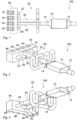
- the input 12 of the cooler 10 may be connected to the output of a turbocharger, not shown in Figures 1 to 11 .
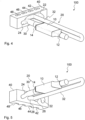
- the internal combustion engine 40 comprises a plurality of cylinders 42, 44, 46, 48, a combustion chamber which is arranged in each cylinder 42, 44, 46, 48, and an air intake system comprising at least a compressor for feeding combustion air, and an air duct arrangement 100, as shown in Figures 1 to 11 .
- the internal combustion engine 40 is only depicted as a schematic part with the cylinder head, exhibiting four cylinders 42, 44, 46, 48 in a single row.
- the second inlet air duct 32 is arranged between the first inlet air duct 30 and the runners 26, 28 connected to an intake valve 54, 56, 58, 60 of the further cylinders 44, 46.
- an air flow length of at least one of the inlet air ducts 30, 32 is provided such that a charge air pressure wave effected by closing the intake valve 50, 52, 54, 56, 58, 60, 62, 64 of one of the cylinders 42, 44, 46, 48 propagates through the inlet air ducts 30, 32 causing an underpressure at the intake valve 50, 52, 54, 56, 58, 60, 62, 64 of the one further cylinder 42, 44, 46, 48.
- the two runners 22, 24 branch off the inlet air duct 30, whereas the two runners 26, 28 branch off the inlet air duct 32.
- Runners 26, 28 are feeding the intake valves 54, 56, 58, 60 of the two adjacent cylinders 44, 46.
- Runners 22, 24 are feeding the intake valves 50, 52, 62, 64 of the two cylinders 42, 48 separated by the two further cylinders 44, 46.
- a specific feature of the air duct arrangement 100 is that the second inlet air duct 32 exhibits a much longer air flow length than the first inlet air duct 30, causing a favorable propagation wave by closing the valves 50, 52, 54, 56, 58, 60, 62, 64 of at least one of the cylinders 42, 44, 46, 48, resulting in an underpressure at the intake valve 50, 52, 54, 56, 58, 60, 62, 64 of the one further cylinder 42, 44, 46, 48.
- This underpressure an advantageous reduction of the input temperature of the charge air may be achieved.
- the internal combustion engine 40 described here operates on the four-stroke principle, with the present invention likewise being suitable for two-stroke internal combustion engine 40s.
- the first inlet air duct 30 is relatively short, connected to the runner 24, feeding cylinder 48.
- the runner 24 is further connected to the runner 22, feeding cylinder 42.
- the second inlet air duct 32 which exhibits a much longer air flow length than the inlet air duct 30, is branching off the connected runners 22, 24 and extends to the connected runners 26, 28, feeding cylinders 44, 46.
- the inlet air ducts 30, 32 are connected via a T-shaped connection part 36 to the cooler 10.
- the first inlet air duct 30 is connected to the runners 22, 24, whereas the second inlet air duct 32 is connected to the runners 26, 28, but in this embodiment the two runners 26, 28 are connected directly upstream the intake valves 54, 56, 58, 60, inside the cylinder head.
Landscapes
- Engineering & Computer Science (AREA)
- Chemical & Material Sciences (AREA)
- Combustion & Propulsion (AREA)
- Mechanical Engineering (AREA)
- General Engineering & Computer Science (AREA)
- Supercharger (AREA)
Claims (13)
- Agencement de conduite d'air (100), en particulier conduite d'air de charge pour moteur à combustion interne turbocompressé (40), comprenant un refroidisseur (10), et au moins deux conduites d'entrée d'air (30, 32) d'un collecteur d'admission d'air (20) d'un moteur à combustion interne (40), dans lequel- au moins une première des conduites d'air d'admission (30, 32) est disposée entre une sortie (14) du refroidisseur (10) et au moins une glissière (22, 24, 26, 28) du collecteur d'admission d'air (20), la glissière (22, 24, 26, 28) étant connectée à une vanne d'admission (50, 52, 54, 56, 58, 60, 62, 64) d'un cylindre (42, 44, 46, 48) du moteur à combustion interne (40),- l'autre des conduites d'air d'admission (30, 32) est disposée entre la première des conduites d'air d'admission (30, 32) et au moins une glissière (22, 24, 26, 28) connectée à une vanne d'admission (50, 52, 54, 56, 58, 60, 62, 64) d'au moins un des autres cylindres (42, 44, 46, 48),caractérisé en ce qu'une longueur de flux d'air d'au moins une des conduites d'air d'admission (30, 32) est prévue de manière à ce qu'une onde de pression d'air de charge produite en fermant la vanne d'admission (50, 52, 54, 56, 58, 60, 62, 64) d'un des cylindres (42, 44, 46, 48) se propage à travers les conduites d'air d'admission (30, 32) en provoquant une sous-pression au niveau de la vanne d'admission (50, 52, 54, 56, 58, 60, 62, 64) de l'autre cylindre supplémentaire (42, 44, 46, 48), les longueurs de flux d'air des conduites d'air d'admission (30, 32) permettant que l'onde de propagation arrive avec une phase appropriée au niveau de la vanne d'admission du second cylindre avec une pression minimale, une longueur de flux d'air très différente étant prévue pour les deux conduites d'air d'admission.
- Agencement de conduite d'air selon la revendication 1, dans lequel au moins deux glissières (22, 24, 26, 28) bifurquent depuis les conduites d'air d'admission (30, 32) .
- Agencement de conduite d'air selon la revendication 1 ou 2, dans lequel les glissières (26, 28) alimentant les vannes d'admission (54, 56, 58, 60) de deux cylindres adjacents (44, 46) bifurquent depuis la même conduite d'air (30, 32).
- Agencement de conduite d'air selon l'une quelconque des revendications précédentes, dans lequel les glissières (22, 24) alimentant les vannes d'admission (50, 52, 62, 64) de deux cylindres (42, 48) séparés par au moins un autre cylindre (44, 46) bifurquent depuis la même conduite d'air (30, 32).
- Agencement de conduite d'air selon l'une quelconque des revendications 3 ou 4, dans lequel deux glissières (26, 28) sont connectées directement en amont des vannes d'admission (54, 56, 58, 60).
- Agencement de conduite d'air selon l'une quelconque des revendications précédentes, dans lequel les conduites d'air d'admission (30, 32) sont pourvues d'un diamètre uniforme sur leur longueur.
- Agencement de conduite d'air selon l'une quelconque des revendications précédentes, dans lequel au moins un cylindre (42, 44, 46, 48) est pourvu de deux vannes d'admission (50, 52, 54, 56, 58, 60, 62, 64) qui sont alimentées par la même glissière (22, 24, 26, 28).
- Agencement de conduite d'air selon l'une quelconque des revendications précédentes, dans lequel au moins une conduite d'air conjointe (34) est disposée entre la sortie (14) du refroidisseur (10) et les conduites d'air d'admission (30, 32).
- Agencement de conduite d'air selon l'une quelconque des revendications précédentes, dans lequel les conduites d'air d'admission (30, 32) sont connectées via un élément de connexion en forme de T (36) au refroidisseur (10) .
- Moteur à combustion interne (40) comprenant au moins :- une pluralité de cylindres (42, 44, 46, 48),- une chambre de combustion qui est disposée dans chaque cylindre (42, 44, 46, 48), un système d'admission d'air comprenant au moins un compresseur pour apporter de l'air de combustion, un agencement de conduite d'air (100) selon l'une quelconque des revendications précédentes.
- Moteur à combustion interne selon la revendication 10, dans lequel au moins deux glissières (22, 24, 26, 28) bifurquent l'une des conduites d'air d'admission (30, 32) .
- Moteur à combustion interne selon la revendication 10 ou 11, dans lequel les glissières (26, 28) alimentant les vannes d'admission (54, 56, 58, 60) de deux cylindres adjacents (44, 46) bifurquent depuis la même conduite d'air (30, 32).
- Moteur à combustion interne selon l'une quelconque des revendications 10 à 12, dans lequel les glissières (22, 24) alimentant les vannes d'admission (50, 52, 62, 64) de deux cylindres (42, 48) séparés par au moins un autre cylindre (44, 46) bifurquent depuis la même conduite d'air (30, 32).
Priority Applications (1)
| Application Number | Priority Date | Filing Date | Title |
|---|---|---|---|
| EP17290162.1A EP3499016B1 (fr) | 2017-12-14 | 2017-12-14 | Agencement de conduite d'air pour moteur à combustion interne |
Applications Claiming Priority (1)
| Application Number | Priority Date | Filing Date | Title |
|---|---|---|---|
| EP17290162.1A EP3499016B1 (fr) | 2017-12-14 | 2017-12-14 | Agencement de conduite d'air pour moteur à combustion interne |
Publications (2)
| Publication Number | Publication Date |
|---|---|
| EP3499016A1 EP3499016A1 (fr) | 2019-06-19 |
| EP3499016B1 true EP3499016B1 (fr) | 2024-07-03 |
Family
ID=60971944
Family Applications (1)
| Application Number | Title | Priority Date | Filing Date |
|---|---|---|---|
| EP17290162.1A Active EP3499016B1 (fr) | 2017-12-14 | 2017-12-14 | Agencement de conduite d'air pour moteur à combustion interne |
Country Status (1)
| Country | Link |
|---|---|
| EP (1) | EP3499016B1 (fr) |
Family Cites Families (5)
| Publication number | Priority date | Publication date | Assignee | Title |
|---|---|---|---|---|
| SE409132B (sv) * | 1976-11-29 | 1979-07-30 | Volvo Ab | Avstemt insugningssystem for en turboladdad forbrenningsmotor |
| HU175877B (en) * | 1978-07-07 | 1980-11-28 | Autoipari Kutato Intezet | Fresh gas duct system of resanator for internal combustion piston engines |
| DE2913264A1 (de) * | 1979-04-03 | 1980-10-23 | Daimler Benz Ag | Saugrohranordnung fuer eine mehrzylindrige brennkraftmaschine mit mindestens vier zylindern, insbesondere acht zylindern |
| DE102007033324A1 (de) | 2007-07-16 | 2009-01-22 | Dr. Ing. H.C. F. Porsche Aktiengesellschaft | Brennkraftmaschine |
| RU2665010C2 (ru) * | 2013-08-26 | 2018-08-24 | Уэстпорт Пауэр Инк. | Прямая система рециркуляции выхлопных газов |
-
2017
- 2017-12-14 EP EP17290162.1A patent/EP3499016B1/fr active Active
Also Published As
| Publication number | Publication date |
|---|---|
| EP3499016A1 (fr) | 2019-06-19 |
Similar Documents
| Publication | Publication Date | Title |
|---|---|---|
| CN103026024B (zh) | 用于对置式活塞发动机的egr结构 | |
| US8671920B2 (en) | Internal combustion engine | |
| US11015553B2 (en) | Exhaust gas recirculation and control with twin scroll turbines | |
| US7287379B2 (en) | Turbo compressor system for internal combustion engine comprising two serially placed turbo units with their rotation axes essentially concentric | |
| US2858666A (en) | Turbocharging of two-cycle engines | |
| CN204175440U (zh) | 用于控制内燃机中的egr系统的系统 | |
| CN104508287B (zh) | 用于导引排气的系统和方法 | |
| US8720402B2 (en) | Internal combustion engine | |
| US8281761B2 (en) | Internal combustion engine | |
| US20180156164A1 (en) | Turbine housings and turbine housing manifolds having integrated bypass valves for dedicated exhaust gas recirculation engines | |
| US7275511B1 (en) | Intake manifold assembly | |
| US5012771A (en) | Intake system for multi-cylinder engine | |
| US7574862B2 (en) | Turbo charger unit comprising double entry turbine | |
| US4760819A (en) | Short pipe manifold for four-stroke engines | |
| EP3499016A1 (fr) | Agencement de conduite d'air pour moteur à combustion interne | |
| CN110230551A (zh) | 具有汽缸盖的内燃发动机和用于生产所述类型的内燃发动机的汽缸盖的方法 | |
| EP3913211B1 (fr) | Véhicule | |
| US11008933B2 (en) | Four stroke internal combustion engine | |
| RU151787U1 (ru) | Двигатель внутреннего сгорания | |
| CN110439661A (zh) | 有高速阀的发动机排气歧管 | |
| JPS6079123A (ja) | 排気タ−ボ過給式多気筒内燃機関 | |
| JP2018155183A (ja) | エンジン |
Legal Events
| Date | Code | Title | Description |
|---|---|---|---|
| PUAI | Public reference made under article 153(3) epc to a published international application that has entered the european phase |
Free format text: ORIGINAL CODE: 0009012 |
|
| STAA | Information on the status of an ep patent application or granted ep patent |
Free format text: STATUS: THE APPLICATION HAS BEEN PUBLISHED |
|
| AK | Designated contracting states |
Kind code of ref document: A1 Designated state(s): AL AT BE BG CH CY CZ DE DK EE ES FI FR GB GR HR HU IE IS IT LI LT LU LV MC MK MT NL NO PL PT RO RS SE SI SK SM TR |
|
| AX | Request for extension of the european patent |
Extension state: BA ME |
|
| RAP1 | Party data changed (applicant data changed or rights of an application transferred) |
Owner name: L'ECOLE CENTRALE DE NANTES Owner name: FORSCHUNGSINSTITUT FUER KRAFTFAHRWESEN UND FAHRZEU Owner name: MANN + HUMMEL GMBH |
|
| STAA | Information on the status of an ep patent application or granted ep patent |
Free format text: STATUS: REQUEST FOR EXAMINATION WAS MADE |
|
| 17P | Request for examination filed |
Effective date: 20191209 |
|
| RBV | Designated contracting states (corrected) |
Designated state(s): AL AT BE BG CH CY CZ DE DK EE ES FI FR GB GR HR HU IE IS IT LI LT LU LV MC MK MT NL NO PL PT RO RS SE SI SK SM TR |
|
| RAP3 | Party data changed (applicant data changed or rights of an application transferred) |
Owner name: MANN+HUMMEL GMBH Owner name: L'ECOLE CENTRALE DE NANTES Owner name: FORSCHUNGSINSTITUT FUER KRAFTFAHRWESEN UND FAHRZEUGMOTOREN STUTTGART |
|
| STAA | Information on the status of an ep patent application or granted ep patent |
Free format text: STATUS: EXAMINATION IS IN PROGRESS |
|
| 17Q | First examination report despatched |
Effective date: 20211223 |
|
| RIN1 | Information on inventor provided before grant (corrected) |
Inventor name: CHALET, DAVID Inventor name: GUENTHER, TORSTEN Inventor name: MIGAUD, JEROME Inventor name: RAIMBAULT, VINCENT |
|
| GRAP | Despatch of communication of intention to grant a patent |
Free format text: ORIGINAL CODE: EPIDOSNIGR1 |
|
| STAA | Information on the status of an ep patent application or granted ep patent |
Free format text: STATUS: GRANT OF PATENT IS INTENDED |
|
| INTG | Intention to grant announced |
Effective date: 20240122 |
|
| GRAS | Grant fee paid |
Free format text: ORIGINAL CODE: EPIDOSNIGR3 |
|
| GRAA | (expected) grant |
Free format text: ORIGINAL CODE: 0009210 |
|
| STAA | Information on the status of an ep patent application or granted ep patent |
Free format text: STATUS: THE PATENT HAS BEEN GRANTED |
|
| RAP1 | Party data changed (applicant data changed or rights of an application transferred) |
Owner name: MOLDTECS-01-2022 GMBH |
|
| AK | Designated contracting states |
Kind code of ref document: B1 Designated state(s): AL AT BE BG CH CY CZ DE DK EE ES FI FR GB GR HR HU IE IS IT LI LT LU LV MC MK MT NL NO PL PT RO RS SE SI SK SM TR |
|
| REG | Reference to a national code |
Ref country code: CH Ref legal event code: EP |
|
| REG | Reference to a national code |
Ref country code: DE Ref legal event code: R096 Ref document number: 602017082950 Country of ref document: DE |
|
| REG | Reference to a national code |
Ref country code: LT Ref legal event code: MG9D |
|
| REG | Reference to a national code |
Ref country code: NL Ref legal event code: MP Effective date: 20240703 |
|
| PG25 | Lapsed in a contracting state [announced via postgrant information from national office to epo] |
Ref country code: PT Free format text: LAPSE BECAUSE OF FAILURE TO SUBMIT A TRANSLATION OF THE DESCRIPTION OR TO PAY THE FEE WITHIN THE PRESCRIBED TIME-LIMIT Effective date: 20241104 |
|
| REG | Reference to a national code |
Ref country code: AT Ref legal event code: MK05 Ref document number: 1700052 Country of ref document: AT Kind code of ref document: T Effective date: 20240703 |
|
| PG25 | Lapsed in a contracting state [announced via postgrant information from national office to epo] |
Ref country code: NL Free format text: LAPSE BECAUSE OF FAILURE TO SUBMIT A TRANSLATION OF THE DESCRIPTION OR TO PAY THE FEE WITHIN THE PRESCRIBED TIME-LIMIT Effective date: 20240703 |
|
| PG25 | Lapsed in a contracting state [announced via postgrant information from national office to epo] |
Ref country code: PT Free format text: LAPSE BECAUSE OF FAILURE TO SUBMIT A TRANSLATION OF THE DESCRIPTION OR TO PAY THE FEE WITHIN THE PRESCRIBED TIME-LIMIT Effective date: 20241104 Ref country code: NL Free format text: LAPSE BECAUSE OF FAILURE TO SUBMIT A TRANSLATION OF THE DESCRIPTION OR TO PAY THE FEE WITHIN THE PRESCRIBED TIME-LIMIT Effective date: 20240703 |
|
| PG25 | Lapsed in a contracting state [announced via postgrant information from national office to epo] |
Ref country code: NO Free format text: LAPSE BECAUSE OF FAILURE TO SUBMIT A TRANSLATION OF THE DESCRIPTION OR TO PAY THE FEE WITHIN THE PRESCRIBED TIME-LIMIT Effective date: 20241003 |
|
| PG25 | Lapsed in a contracting state [announced via postgrant information from national office to epo] |
Ref country code: GR Free format text: LAPSE BECAUSE OF FAILURE TO SUBMIT A TRANSLATION OF THE DESCRIPTION OR TO PAY THE FEE WITHIN THE PRESCRIBED TIME-LIMIT Effective date: 20241004 Ref country code: FI Free format text: LAPSE BECAUSE OF FAILURE TO SUBMIT A TRANSLATION OF THE DESCRIPTION OR TO PAY THE FEE WITHIN THE PRESCRIBED TIME-LIMIT Effective date: 20240703 Ref country code: PL Free format text: LAPSE BECAUSE OF FAILURE TO SUBMIT A TRANSLATION OF THE DESCRIPTION OR TO PAY THE FEE WITHIN THE PRESCRIBED TIME-LIMIT Effective date: 20240703 |
|
| PG25 | Lapsed in a contracting state [announced via postgrant information from national office to epo] |
Ref country code: BG Free format text: LAPSE BECAUSE OF FAILURE TO SUBMIT A TRANSLATION OF THE DESCRIPTION OR TO PAY THE FEE WITHIN THE PRESCRIBED TIME-LIMIT Effective date: 20240703 |
|
| PG25 | Lapsed in a contracting state [announced via postgrant information from national office to epo] |
Ref country code: LV Free format text: LAPSE BECAUSE OF FAILURE TO SUBMIT A TRANSLATION OF THE DESCRIPTION OR TO PAY THE FEE WITHIN THE PRESCRIBED TIME-LIMIT Effective date: 20240703 |
|
| PG25 | Lapsed in a contracting state [announced via postgrant information from national office to epo] |
Ref country code: AT Free format text: LAPSE BECAUSE OF FAILURE TO SUBMIT A TRANSLATION OF THE DESCRIPTION OR TO PAY THE FEE WITHIN THE PRESCRIBED TIME-LIMIT Effective date: 20240703 Ref country code: IS Free format text: LAPSE BECAUSE OF FAILURE TO SUBMIT A TRANSLATION OF THE DESCRIPTION OR TO PAY THE FEE WITHIN THE PRESCRIBED TIME-LIMIT Effective date: 20241103 |
|
| PG25 | Lapsed in a contracting state [announced via postgrant information from national office to epo] |
Ref country code: CZ Free format text: LAPSE BECAUSE OF FAILURE TO SUBMIT A TRANSLATION OF THE DESCRIPTION OR TO PAY THE FEE WITHIN THE PRESCRIBED TIME-LIMIT Effective date: 20240703 Ref country code: HR Free format text: LAPSE BECAUSE OF FAILURE TO SUBMIT A TRANSLATION OF THE DESCRIPTION OR TO PAY THE FEE WITHIN THE PRESCRIBED TIME-LIMIT Effective date: 20240703 |
|
| PG25 | Lapsed in a contracting state [announced via postgrant information from national office to epo] |
Ref country code: ES Free format text: LAPSE BECAUSE OF FAILURE TO SUBMIT A TRANSLATION OF THE DESCRIPTION OR TO PAY THE FEE WITHIN THE PRESCRIBED TIME-LIMIT Effective date: 20240703 Ref country code: RS Free format text: LAPSE BECAUSE OF FAILURE TO SUBMIT A TRANSLATION OF THE DESCRIPTION OR TO PAY THE FEE WITHIN THE PRESCRIBED TIME-LIMIT Effective date: 20241003 |
|
| PG25 | Lapsed in a contracting state [announced via postgrant information from national office to epo] |
Ref country code: RS Free format text: LAPSE BECAUSE OF FAILURE TO SUBMIT A TRANSLATION OF THE DESCRIPTION OR TO PAY THE FEE WITHIN THE PRESCRIBED TIME-LIMIT Effective date: 20241003 Ref country code: PL Free format text: LAPSE BECAUSE OF FAILURE TO SUBMIT A TRANSLATION OF THE DESCRIPTION OR TO PAY THE FEE WITHIN THE PRESCRIBED TIME-LIMIT Effective date: 20240703 Ref country code: NO Free format text: LAPSE BECAUSE OF FAILURE TO SUBMIT A TRANSLATION OF THE DESCRIPTION OR TO PAY THE FEE WITHIN THE PRESCRIBED TIME-LIMIT Effective date: 20241003 Ref country code: LV Free format text: LAPSE BECAUSE OF FAILURE TO SUBMIT A TRANSLATION OF THE DESCRIPTION OR TO PAY THE FEE WITHIN THE PRESCRIBED TIME-LIMIT Effective date: 20240703 Ref country code: IS Free format text: LAPSE BECAUSE OF FAILURE TO SUBMIT A TRANSLATION OF THE DESCRIPTION OR TO PAY THE FEE WITHIN THE PRESCRIBED TIME-LIMIT Effective date: 20241103 Ref country code: HR Free format text: LAPSE BECAUSE OF FAILURE TO SUBMIT A TRANSLATION OF THE DESCRIPTION OR TO PAY THE FEE WITHIN THE PRESCRIBED TIME-LIMIT Effective date: 20240703 Ref country code: GR Free format text: LAPSE BECAUSE OF FAILURE TO SUBMIT A TRANSLATION OF THE DESCRIPTION OR TO PAY THE FEE WITHIN THE PRESCRIBED TIME-LIMIT Effective date: 20241004 Ref country code: FI Free format text: LAPSE BECAUSE OF FAILURE TO SUBMIT A TRANSLATION OF THE DESCRIPTION OR TO PAY THE FEE WITHIN THE PRESCRIBED TIME-LIMIT Effective date: 20240703 Ref country code: ES Free format text: LAPSE BECAUSE OF FAILURE TO SUBMIT A TRANSLATION OF THE DESCRIPTION OR TO PAY THE FEE WITHIN THE PRESCRIBED TIME-LIMIT Effective date: 20240703 Ref country code: CZ Free format text: LAPSE BECAUSE OF FAILURE TO SUBMIT A TRANSLATION OF THE DESCRIPTION OR TO PAY THE FEE WITHIN THE PRESCRIBED TIME-LIMIT Effective date: 20240703 Ref country code: BG Free format text: LAPSE BECAUSE OF FAILURE TO SUBMIT A TRANSLATION OF THE DESCRIPTION OR TO PAY THE FEE WITHIN THE PRESCRIBED TIME-LIMIT Effective date: 20240703 Ref country code: AT Free format text: LAPSE BECAUSE OF FAILURE TO SUBMIT A TRANSLATION OF THE DESCRIPTION OR TO PAY THE FEE WITHIN THE PRESCRIBED TIME-LIMIT Effective date: 20240703 |
|
| REG | Reference to a national code |
Ref country code: DE Ref legal event code: R097 Ref document number: 602017082950 Country of ref document: DE |
|
| PG25 | Lapsed in a contracting state [announced via postgrant information from national office to epo] |
Ref country code: SM Free format text: LAPSE BECAUSE OF FAILURE TO SUBMIT A TRANSLATION OF THE DESCRIPTION OR TO PAY THE FEE WITHIN THE PRESCRIBED TIME-LIMIT Effective date: 20240703 Ref country code: RO Free format text: LAPSE BECAUSE OF FAILURE TO SUBMIT A TRANSLATION OF THE DESCRIPTION OR TO PAY THE FEE WITHIN THE PRESCRIBED TIME-LIMIT Effective date: 20240703 Ref country code: DK Free format text: LAPSE BECAUSE OF FAILURE TO SUBMIT A TRANSLATION OF THE DESCRIPTION OR TO PAY THE FEE WITHIN THE PRESCRIBED TIME-LIMIT Effective date: 20240703 |
|
| PG25 | Lapsed in a contracting state [announced via postgrant information from national office to epo] |
Ref country code: EE Free format text: LAPSE BECAUSE OF FAILURE TO SUBMIT A TRANSLATION OF THE DESCRIPTION OR TO PAY THE FEE WITHIN THE PRESCRIBED TIME-LIMIT Effective date: 20240703 |
|
| PG25 | Lapsed in a contracting state [announced via postgrant information from national office to epo] |
Ref country code: IT Free format text: LAPSE BECAUSE OF FAILURE TO SUBMIT A TRANSLATION OF THE DESCRIPTION OR TO PAY THE FEE WITHIN THE PRESCRIBED TIME-LIMIT Effective date: 20240703 Ref country code: SK Free format text: LAPSE BECAUSE OF FAILURE TO SUBMIT A TRANSLATION OF THE DESCRIPTION OR TO PAY THE FEE WITHIN THE PRESCRIBED TIME-LIMIT Effective date: 20240703 |
|
| PLBE | No opposition filed within time limit |
Free format text: ORIGINAL CODE: 0009261 |
|
| STAA | Information on the status of an ep patent application or granted ep patent |
Free format text: STATUS: NO OPPOSITION FILED WITHIN TIME LIMIT |
|
| 26N | No opposition filed |
Effective date: 20250404 |
|
| PG25 | Lapsed in a contracting state [announced via postgrant information from national office to epo] |
Ref country code: MC Free format text: LAPSE BECAUSE OF FAILURE TO SUBMIT A TRANSLATION OF THE DESCRIPTION OR TO PAY THE FEE WITHIN THE PRESCRIBED TIME-LIMIT Effective date: 20240703 |
|
| REG | Reference to a national code |
Ref country code: CH Ref legal event code: PL |
|
| PG25 | Lapsed in a contracting state [announced via postgrant information from national office to epo] |
Ref country code: LU Free format text: LAPSE BECAUSE OF NON-PAYMENT OF DUE FEES Effective date: 20241214 |
|
| GBPC | Gb: european patent ceased through non-payment of renewal fee |
Effective date: 20241214 |
|
| PG25 | Lapsed in a contracting state [announced via postgrant information from national office to epo] |
Ref country code: SE Free format text: LAPSE BECAUSE OF FAILURE TO SUBMIT A TRANSLATION OF THE DESCRIPTION OR TO PAY THE FEE WITHIN THE PRESCRIBED TIME-LIMIT Effective date: 20240703 |
|
| REG | Reference to a national code |
Ref country code: BE Ref legal event code: MM Effective date: 20241231 |
|
| PG25 | Lapsed in a contracting state [announced via postgrant information from national office to epo] |
Ref country code: GB Free format text: LAPSE BECAUSE OF NON-PAYMENT OF DUE FEES Effective date: 20241214 Ref country code: BE Free format text: LAPSE BECAUSE OF NON-PAYMENT OF DUE FEES Effective date: 20241231 |
|
| PG25 | Lapsed in a contracting state [announced via postgrant information from national office to epo] |
Ref country code: CH Free format text: LAPSE BECAUSE OF NON-PAYMENT OF DUE FEES Effective date: 20241231 |
|
| PG25 | Lapsed in a contracting state [announced via postgrant information from national office to epo] |
Ref country code: IE Free format text: LAPSE BECAUSE OF NON-PAYMENT OF DUE FEES Effective date: 20241214 |
|
| PGFP | Annual fee paid to national office [announced via postgrant information from national office to epo] |
Ref country code: DE Payment date: 20251211 Year of fee payment: 9 |
|
| PGFP | Annual fee paid to national office [announced via postgrant information from national office to epo] |
Ref country code: FR Payment date: 20251222 Year of fee payment: 9 |
|
| PG25 | Lapsed in a contracting state [announced via postgrant information from national office to epo] |
Ref country code: CY Free format text: LAPSE BECAUSE OF FAILURE TO SUBMIT A TRANSLATION OF THE DESCRIPTION OR TO PAY THE FEE WITHIN THE PRESCRIBED TIME-LIMIT Effective date: 20240703 |