EP3499247B1 - Interface isolée galvaniquement et procédé de transmission de signaux analogiques par l'intermédiaire de ladite interface - Google Patents
Interface isolée galvaniquement et procédé de transmission de signaux analogiques par l'intermédiaire de ladite interface Download PDFInfo
- Publication number
- EP3499247B1 EP3499247B1 EP18020617.9A EP18020617A EP3499247B1 EP 3499247 B1 EP3499247 B1 EP 3499247B1 EP 18020617 A EP18020617 A EP 18020617A EP 3499247 B1 EP3499247 B1 EP 3499247B1
- Authority
- EP
- European Patent Office
- Prior art keywords
- voltage
- coil
- branch
- winding
- interface
- Prior art date
- Legal status (The legal status is an assumption and is not a legal conclusion. Google has not performed a legal analysis and makes no representation as to the accuracy of the status listed.)
- Active
Links
Images

Classifications
-
- G—PHYSICS
- G01—MEASURING; TESTING
- G01R—MEASURING ELECTRIC VARIABLES; MEASURING MAGNETIC VARIABLES
- G01R15/00—Details of measuring arrangements of the types provided for in groups G01R17/00 - G01R29/00, G01R33/00 - G01R33/26 or G01R35/00
- G01R15/14—Adaptations providing voltage or current isolation, e.g. for high-voltage or high-current networks
- G01R15/18—Adaptations providing voltage or current isolation, e.g. for high-voltage or high-current networks using inductive devices, e.g. transformers
- G01R15/183—Adaptations providing voltage or current isolation, e.g. for high-voltage or high-current networks using inductive devices, e.g. transformers using transformers with a magnetic core
-
- H—ELECTRICITY
- H01—ELECTRIC ELEMENTS
- H01F—MAGNETS; INDUCTANCES; TRANSFORMERS; SELECTION OF MATERIALS FOR THEIR MAGNETIC PROPERTIES
- H01F19/00—Fixed transformers or mutual inductances of the signal type
- H01F19/04—Transformers or mutual inductances suitable for handling frequencies considerably beyond the audio range
- H01F19/08—Transformers having magnetic bias, e.g. for handling pulses
- H01F2019/085—Transformer for galvanic isolation
-
- H—ELECTRICITY
- H01—ELECTRIC ELEMENTS
- H01F—MAGNETS; INDUCTANCES; TRANSFORMERS; SELECTION OF MATERIALS FOR THEIR MAGNETIC PROPERTIES
- H01F27/00—Details of transformers or inductances, in general
- H01F27/40—Structural association with built-in electric component, e.g. fuse
- H01F27/402—Association of measuring or protective means
Definitions
- the invention relates to an electrical interface with galvanic isolation for a pump unit and a method for the galvanically isolated transmission of analog signals via this interface.
- Standardized signals are often used for this, e.g. an analog 0-10 voltage signal, an analog 4-20mA current signal or a pulse width modulated (PWM) signal, which is a digital square wave signal in type and form.
- PWM pulse width modulated
- Such signals are used, for example, by control devices to control another device.
- the signal then forms a control signal and usually represents a setpoint in terms of control technology.
- measuring devices also often use the standardized signals mentioned, which then form corresponding measuring signals which are processed by the device electronics.
- the interface has galvanic isolation so that an electrical fault, in particular a short circuit, on one side of the interface does not affect the other side.
- transformers or optocouplers are used for electrical isolation.
- the PWM signal is an alternating signal
- the analog voltage and current signal is a sectionally constant signal, that is to say a DC signal, which is why, according to the state of the art, it precedes the Transmission pre-processed across the galvanic isolation, in particular digitized and converted into an alternating signal.
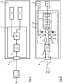
- FIG. 1 An example of a known interface 2 shows Figure 1 ,
- an optocoupler 6 is used here, the output signal of which is sent to the electronics 9.
- the preprocessing is carried out by means of a microcontroller 5, which in turn is connected to the interface input 4a, 4b.
- a first interface input 4a is provided for analog input signals and a second interface input 4b for digital signals. These are connected to two corresponding inputs on the microcontroller 5. Since the preprocessing or the microcontroller 5 requires a voltage supply, a second electrical isolation is required, which takes place here in the form of a transformer 7. This receives a voltage from a voltage supply 8.
- DE10 2005 007378 discloses a device for inductive detection of a direct current.
- a central transformer the second winding of which is supplied with an "interrogation signal", a decision (for switching) then being made via a fixed measuring resistor, after rectification, amplification and comparison.
- the aim here is to compensate for a temperature dependency of the permeability of the ferrite of the transformer core by means of a temperature-dependent change in the polling interrogation signal.
- an electrical interface for a pump unit for the galvanically isolated transmission of an analog input signal to electronics comprising an interface input, a Transformer with a first and a second winding and a measuring circuit, the two windings being coupled in a magnetic circuit, the first winding being connected to the interface input for applying an analog input signal and the second winding being connected to the measuring circuit.
- the measuring circuit comprises a changeable resistor circuit with which the second winding is connected. Furthermore, the measuring circuit is set up to apply a changing voltage to the second winding by changing the resistor circuit, to determine a time period from the time course of at least one electrical variable of the resistor circuit and to determine the level of the input signal therefrom.
- a core aspect of the invention is therefore to carry out the transmission of an analog input signal via a transformer, the input signal being applied to the first winding of the transformer and causing magnetic flux inside the core of the transformer and thus a change in its permeability.
- the resulting change in inductance is then evaluated on the basis of the time profile of an electrical variable of the measuring circuit.
- the interface according to the invention is provided for a pump unit.
- the invention thus also relates to a pump unit which has an interface according to the invention.
- the pump unit can preferably be a centrifugal pump unit.
- the interface according to the invention enables the galvanically isolated transmission of analog input signals such as a 0-10V control or measurement signal from the interface input to an electronics of the pump unit using a single galvanic isolation, which is implemented here in the form of the transformer.
- the interface therefore has no other component to galvanically separate the interface input from the pump electronics. Furthermore, no DC-AC conversion of the input signal is required before the first winding, so that the interface has a small overall space.
- the interface according to the invention and the method implemented in it enable the galvanically isolated transmission of analog signals which are constant in sections, i.e. Equal sizes. These change over a longer period, e.g. Not seconds, minutes or hours.
- analog signals which are constant in sections, i.e. Equal sizes. These change over a longer period, e.g. Not seconds, minutes or hours.
- Such signals cannot easily be transmitted via a transformer, since in order to be able to induce a voltage on the output winding, an alternating flux is required, which must be generated by the input winding.
- a constant signal only produces a constant flow. Therefore, a transformer can only transmit constant values.
- the measuring circuit applies an alternating voltage to the measuring circuit by changing the resistance circuit with which the second winding is connected.
- the second winding in the transformer core generates an alternating basic magnetic flux.
- the constant magnetic flux generated by the input signal is superimposed on the basic flux and thereby influences the inductance of the transformer, which in turn determines the time constant with which the electrical quantities of the resistor circuit, i.e. change on the side of the second winding.
- One aspect of the method according to the invention is to determine the level of the input signal from this time-characteristic course of at least one electrical variable of the resistance circuit, which is determined by the time constant.
- the transformer core is a soft magnetic material. This has the advantage that the remanence and the hysteresis are close to zero.
- the changing basic flow should only be a fraction of the constant flow generated by the first winding, for example less than 20% of this flow, in particular approximately 10%.
- This can be achieved, for example, by a suitable ratio of the number of turns of the first winding to the second winding.
- the turns ratio is preferably between 1:10 to 1:20. The larger the turns ratio the more accurate the measurement is.
- In the first winding there is a maximum limit on the number of turns due to the spatial conditions. This maximum limit therefore depends on the size of the core. For example, the first winding may have 120 turns. A lower limit for the number of turns must be observed on the part of the second winding. If the number of turns of the second winding is reduced, the influence of the hysteresis becomes greater and has a negative influence on the measurement. Studies have shown that, for example, 7 turns in the second winding lead to good results.
- the change in the resistance circuit can be periodic. This means that the voltage applied to the second winding changes at a certain frequency.
- this frequency can be between 1 kHz and 20 kHz, preferably 8 kHz.
- the frequencies can be used that are often used in motor controls of pump units.
- first and the second winding are wound with the same winding direction. This means that with a positive current flow through the respective winding, a positive magnetic flux is generated and that these flows are directed in the same direction. This ensures that the changing basic flow is only increased, ie not reduced, by the constant flow generated by the input signal.
- the resistor circuit forms a voltage divider, the second winding being in a first branch of the voltage divider. It is preferably connected in series with at least one resistor.
- it can be a resistor that connects the second winding to a supply voltage or to ground.
- there can be a series resistor in the first branch with which the second winding is connected in series.
- this series resistance can also be dispensed with.
- the electrically effective resistance value of a branch of the voltage divider can be changed. This means that the changing voltage on the winding is caused by the fact that the actually acting electrical resistance of the circuit is changed alternately. This can be done in a variety of ways, for example by adding or disconnecting one or more resistors in the resistor circuit.
- the resistor circuit comprises two resistors, the second winding being selectively switchable in series with one or two of the resistors between a supply voltage and ground.
- the measuring circuit is set up to alternately connect the second winding with one or two of the resistors in series between the supply voltage and ground.
- the first branch can be connected or connectable to the supply voltage via a first resistor and connected or connectable to ground via a second resistor.
- the first branch lies between the first and the second resistor and comprises only the second winding.
- Such a circuit is useful if the internal resistance of the second winding is sufficiently large, for example at least a few ohms.
- the resistor circuit comprises at least three resistors, the second winding being selectively switchable in series with two or three of the resistors between a supply voltage and ground.
- the measuring circuit is set up to alternately connect the second winding with two or three of the resistors in series between the supply voltage and ground.
- the first branch can be connected or connectable to the supply voltage via a first resistor and connected or connectable to ground via a second resistor.
- the first branch is between the first and second resistors and includes a third resistor in series with the second winding.
- Such a circuit is useful if the internal resistance of the second winding is small, in particular less than one ohm.
- the first and the second resistor can be the same size.
- they can range from 10 ⁇ to 1k ⁇ .
- the third resistance can be smaller.
- its value can be one tenth or less of the value of the first or second resistor.
- the resistor circuit can have, for example, a controllable switch, in particular a controllable semiconductor switch, in order to change the resistor circuit depending on the state.
- a controllable switch in particular a controllable semiconductor switch
- This switch is suitably connected in parallel or in series with a resistor of the resistor circuit. In the case of a parallel switch, this bridges the resistor in its closed state, so that the effect of this resistor is canceled.
- the resistance acts against it.
- the resistance only acts when the switch is closed, while it does not work when the switch is open.
- a particularly simple, changeable resistor circuit is achieved if the first branch can be connected to ground via the switch.
- the first branch can be connected to a supply voltage via the switch.
- the measuring circuit is preferably set up to switch the switch on and off alternately, in particular to control it with a frequency between 1 kHz and 20 kHz, preferably with about 8 kHz.
- the resistor circuit is changed periodically with this frequency, and that at the second winding voltage changes with the frequency of the drive signal of the switch.
- the clock ratio is preferably selected such that the duration of the state of the switch in which the second winding with fewer resistors is in series is shorter than the duration of the state of the switch in which the second winding with more resistors is in series lies. This takes into account the fact that with a larger number of resistors in series with the second winding, the effective total resistance is higher and the second winding is thereby charged more slowly. Therefore, it takes longer in this case until the steady state is reached. However, this state does not necessarily have to be reached. Rather, the switch can be switched before this state is reached. According to a preferred embodiment variant, the cycle ratio is therefore selected such that the duration of the switch-on state is shorter than the duration of the switch-off state.
- the at least one electrical variable of the resistance circuit that is used to determine the level of the input signal is the voltage on the second winding, in particular on the first branch.
- the measuring circuit can comprise a signal evaluation unit which is parallel to the first branch.
- the voltage on the first branch or on the winding is available to the signal evaluation unit in order to evaluate this.
- the signal evaluation unit can have a comparator for comparing the potential at the input node of the first branch with the potential at the output node of the first branch.
- the input node is the node of the resistor circuit into which a positive current flows first branch flows in
- the output node is the node of the resistor circuit from which a positive current flows out of the first branch.
- the comparator can be a comparator.
- An output signal is obtained by this comparator, which indicates whether the voltage at the input node is greater or less than the voltage at the output node.
- the output signal of the comparator can be zero or ground if the voltage at the input node is less than the voltage at the output node. Accordingly, the output signal of the comparator can be at logic one (potential of the supply voltage V1) if the voltage at the input node is greater than the voltage at the output node.
- the comparator can be set up to generate an output signal that is greater or less than zero depending on the ratio of the voltage at the input node to the voltage at the output node.
- the comparator can work in the manner of a differentiator, i.e. the difference between the voltage at the input node and the voltage at the output node is formed and their sign is output at the output of the comparator.
- the comparator can be set up to generate an output signal that is greater or less than one, depending on the ratio of the voltage at the input node to the voltage at the output node.
- the comparator can work in the manner of a divider, i.e. that the ratio of the voltage at the input node and the voltage at the output node is formed and their ratio is output at the output of the comparator.
- the comparator can be a discrete, independent electronic component or, as a function module, part of a larger electronics module with several function units, such as a microprocessor or a microcontroller. In this the comparator can only be used in hardware be trained. Alternatively, it can also be partially or completely implemented by software.
- the signal evaluation unit can comprise a timer which is set up to start a counter when the output signal of the comparator changes for the first time and to stop the counter when the output signal of the comparator changes for the second time.
- the counter value that is present when the counter is stopped then describes the specific time period.
- the timer called timer, forms a kind of stopwatch.
- the timer can also be a discrete, independent electronic component, for example formed by an integrator.
- the timer is electrically connected downstream of the comparator, so that the output of the comparator is connected to the input of the timer.
- a function module it can be part of a larger electronics module with several function units, such as a DSP, a microprocessor or a microcontroller.
- the timer can be designed exclusively in hardware. Alternatively, it can also be implemented by software. If the comparator and the timer are both functional units of the larger electronic module, the timer is functionally subordinate to the comparator.
- the signal evaluation unit can comprise an allocator which is set up to determine the level of the input signal from the derived time period.
- the output of the timer is electrically or at least functionally connected to the input of the allocator, so that the determined time period T is fed to it.
- This is then assigned a specific value of the input variable by the assignor.
- U E f (T) or as part of a tabular assignment that can or is stored in the assignor.
- the relationship between the time period T and the input signal U E may have been determined in the factory and stored in the signal evaluation.
- the assignor then gives on his Output a value corresponding to the value of the input signal U E , which can or will be sent to the electronics for further processing.
- the assignor can also be a discrete, independent electronic, in particular programmable, component such as an FPGA, DSP, a microprocessor, or a microcontroller, the assignment to be carried out by the assignor preferably being implemented using software.
- the allocator thus consists partly of software and partly of hardware.
- the allocator can include a memory for storing the relationship between the time period T and the input signal U E. This can be part of the programmable component or a memory component arranged and connected to it externally, for example an EEPROM.
- the signal evaluation unit is a microcontroller, in which the comparator, the counter and / or the allocator form, in particular in each case one function unit, in particular are implemented.
- the comparator, the counter and / or the allocator are housed together in a larger electronic component, the microcontroller.
- the wiring effort is minimal and signal processing between comparator, counter and allocator is particularly easy to design.
- the signal evaluation unit is preferably also set up to generate the control signal for the switch. This can be done, for example, by a frequency generator, which can also be part of the signal evaluation unit, in particular part of the microcontroller.
- the pump unit in which the interface according to the invention is present is, for example, a centrifugal pump unit, such as those used for heating or cooling systems or in the drinking water supply.
- Centrifugal pump units of this type consist of an electromotive drive unit, a pump unit driven by the latter and motor electronics which control the motor and preferably regulate the pump.
- the interface according to the invention can be part of this motor electronics, which due to the pump regulating or controlling function is also called pump electronics.
- the motor electronics or pump electronics can structurally form a unit with the motor. Alternatively, however, it can also be mounted only on the latter or can be provided for an arrangement external to the motor, for example for wall mounting. A structural connection between the motor electronics or pump electronics and the rest of the pump unit is therefore not necessary.
- the pump unit in which the interface according to the invention is present can also be formed by a pump system which comprises two or more functionally interacting centrifugal pump units. These can be controlled by a common motor electronics or pump electronics, which can be installed separately from the motors of the centrifugal pump units, in particular centrally, so that there is no structural connection to the motor units here either.
- the change is preferably made periodically, so that the alternating voltage is also a periodic alternating voltage. This simplifies the determination of the time period.
- the alternating voltage is generated by alternately switching the second winding with two or three resistors between a supply voltage and ground.
- the time period is preferably determined from the voltage on a first branch of the resistor circuit, which comprises the second winding or a series circuit comprising the second winding and a series resistor. This voltage forms the aforementioned electrical quantity.
- the time period can be determined, for example, by means of a comparator, in particular a comparator, which is parallel to the first branch and whose output signal changes when the voltage on the first branch changes its sign.
- the time period to be determined is the period between two successive sign changes.
- the effect is advantageously exploited that when the resistance circuit is changed, the sign of the voltage acting on the second winding changes abruptly, namely becomes negative and only then gradually strives towards the steady state, which is, however, a positive voltage.
- the self-induction voltage receives a new change of sign, which can be determined by the comparator and which takes place at a specific point in time, which is determined by the currently acting inductance of the second winding and by the currently acting total resistance of the resistor circuit. In other words, this point in time changes depending on the inductance acting. Since there is a linear relationship here, the point in time is pushed back in time by increasing the inductance and pushed forward in time by reducing the inductance. Since the inductance is in turn linearly related to the permeability, the same applies to the relationship between the point in time and the permeability.
- the permeability in turn depends on the level of the input signal, there is also a connection between the input signal and the point in time such that an increased input signal shifts the point in time forward and a lower input signal shifts the point in time backwards.
- the named point in time forms the end of the mentioned period, the beginning of which is at the time of the previous change of sign of the voltage on the first branch. This time coincides with a switchover time of the switch, in a preferred embodiment variant in particular when the switch is opened, as a result of which a resistor lying parallel to the switch becomes active and connects the first branch to ground.
- a counter is preferably started when the output signal of the comparator changes its value.
- the counter is stopped again when the output signal of the comparator changes back to the previous value.
- the counter reading of the counter then represents the time period to be determined.
- the counter can be Timer be realized.
- a height of the input signal is preferably assigned to the determined time period from a stored mathematical or tabular context. This can be done using the previously described assignor.
- the measurement of the period is always carried out in the same area of the hysteresis curve, i.e. the magnetization curve is not repeated.
- This can be achieved by performing a cyclic bias, for example by cyclically closing the switch for a longer period. This means that the core of the transformer is set to a defined bias.
- Figure 1 shows a block diagram of an electrical interface 2 of a pump unit 1 with electrical isolation 6, 7, as used in the prior art for the transmission of analog 0-10V signals 3a and digital PWM signals 3b and has already been described in the introduction to the description.
- FIG. 2 shows a block diagram that describes the basic structure of the interface 2 according to the invention with electrical isolation.
- This galvanic isolation takes place via a transformer 7 with a first winding L1 and a second winding L2, which are coupled to one another in a magnetic circuit.
- both windings L1, L2 are wound together on an annular transformer core.
- the interface 2 dispenses with preprocessing of the analog input signals 3a and with further galvanic isolation. Rather, the first winding L1 is connected directly to an interface input 4, to which the analog input signal 3a is applied, so that the input signal 3a is applied to the first winding L1. It therefore forms an input winding.
- a measuring circuit 10 is provided in the interface 2, which is connected to the second winding L2 of the transformer 7.
- the second winding L2 thus forms a measuring winding.
- the measuring circuit 10 is supplied with voltage on the one hand from a voltage source 8 of the pump unit 1.
- the measuring circuit 10 determines the level of the analog input signal 3a and outputs it for forwarding to electronics 9 (motor electronics or pump electronics).
- the basic idea of the interface 2 according to the invention is to determine the influence of the input signal 3a on a physical variable of the component causing the electrical isolation and from this influence on the level of the Close input signal.
- the measuring circuit 10 is set up accordingly.
- the physical quantity mentioned is the inductance of the second winding, which changes more or less depending on the level of the input signal 3a applied.
- the level of the input signal is inferred from the change in inductance.
- a voltage U E is applied to the first winding L1
- a current flow I L1 is established through the first winding L1.
- This current flow I L1 generates an external magnetic H field.
- the external magnetic H field creates a magnetic flux in the transformer core.
- This magnetic flux is described by the B field.
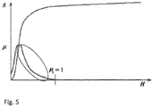
- the increase in the outer H field leads to a strong or less strong increase in the B field.
- the permeability ⁇ is not a constant factor, but has an essentially parabola-like course due to the nucleus saturating (the B field no longer increases for increasing H values).
- L 1 ⁇ * N 1 2 * A lm
- L 1 the first winding
- ⁇ the permeability
- N 1 the number of turns of the first winding
- A cross-sectional area of the core
- Im the mean circumference of the core is the mean magnetic path length.
- the inductance has one Proportionality to ⁇ . It follows from this that the inductance of the first winding L1 also has a parabola-like profile when the H field is increased.
- a key aspect of the invention is to use a relationship between the changing inductance of the second winding L2, hereinafter referred to as measuring inductance, and the input signal or the input current I E fed in at the interface input 4.
- measuring inductance the changing inductance of the second winding L2
- I E the input current
- N 1 corresponds to the number of turns of the first winding L1 and Im the middle circumference of the transformer core.
- the formula shows that the field strength H is proportional to the input current.
- FIG. 3 shows an exemplary embodiment of the circuit of an interface 2 according to the invention.
- the measuring circuit 10 of the interface 2 comprises a resistance circuit which is connected to the second inductor L2.
- the resistor circuit here consists of three resistors as an example.
- a first resistor Rs is in series with the second winding L2 and is therefore called Series resistance Rs designated.
- Series resistor Rs and second winding L2 form a first branch with an input node 16 and an output node 17.
- This first branch is connected via a second resistor R1 to a supply voltage V1, which is provided by the voltage supply 8 of the pump unit 1.
- the first branch is also connected to ground via a third resistor R2.
- a diode D1, D2 is connected in parallel with the second and third resistor.
- a controlled switch T1 in particular a semiconductor switch such as a transistor (bipolar or MOSFET transistor), which bridges the third resistor in the closed state and thereby connects the first branch to ground, is connected in parallel with the third resistor R2.
- the effectiveness of the third resistor R2 can thus be switched off, the resistor circuit can consequently be changed by opening or closing the switch T1.
- a periodic control voltage U st in the form of a square wave signal is used, which switches the switch T1 on and off alternately.
- the control voltage U st can be generated by the measuring circuit, in particular a microcontroller thereof.
- a periodic control signal Ust is applied to the control input of the switch T 1 , as a result of which the switch T 1 opens and closes alternately.
- the control signal is preferably a square wave signal.
- the control signal suitably has a frequency between 1 kHz and 20 kHz, for example 8 kHz.
- the control signal Ust can be generated, for example, by a frequency generator. Such a frequency generator can preferably be part of the measuring circuit 10.
- the control signal U St is selected so that the on state is shorter is present as the off state of the switch T1. A duty cycle of approximately 30% is selected.
- resistor R2 By closing switch T1, resistor R2 is bridged and the first branch is switched to ground. Closing switch T1 connects the second branch to ground via resistor Rs. Then the resistors Rs, R 1 , together with the second winding L2, are connected in series between the supply voltage V1 and ground. The switch T1 is thus able to change the resistor circuit.
- the periodic switching of the switch T1 also periodically switches or bridges the third resistor R 2 in series with the first branch. As a result, this means that two different voltages can be alternately impressed on the second winding L2. This results in two different voltage values at the input node 16 and output node 17 for the steady state, ie at the terminals of the measuring inductance L 1 . This is given below using a numerical example.
- a voltage supply V 1 of, for example, 5V is used.
- the resistor circuit forms a voltage divider, so that the following stationary voltages with respect to ground at input node 16 and output node 17 result according to the voltage divider rule:
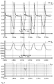
- Fig. 4 illustrates which shows a diagram of the time profile of the voltages U L2 + and U L2- at the input and output terminals 16, 17 of the first branch. This course is based on Lenz's rule: If the magnetic flux in a coil is changed, a current flow is generated by the self-induction voltage, which is always directed so that a magnetic field arises which counteracts the change in the magnetic flux.
- the switch T1 is opened before the voltage at the input terminal 16 has reached its stationary value.
- the third resistor R2 is thereby suddenly connected in series with the first branch. Due to the continuity of the current, the current flowing at the time of switching (about 29mA) flows through the third resistor R2, so that a corresponding voltage drop occurs immediately (about 4.35V), causing the voltage at the output terminal 17 to the value of this Voltage drop is raised. At this moment, however, the voltage at the input terminal 16 is still unchanged (at approximately 0.65 V), so that the voltage at the output terminal 17 has risen above the voltage at the input terminal. Thus the total voltage across the first branch has become negative. Since the resistor circuit forms a voltage divider, on which the supply voltage V1 (5V) drops and the same current (approx.
- the curves of the voltages of input and output terminals 16, 17 of the first branch At this point, the voltage across the first branch is zero, ie the voltage U RS across the series resistor Rs and the voltage U L2 across the second winding L 2 are of the same magnitude, but have opposite signs and therefore cancel each other out.
- L is the inductance of the second winding L 2 .
- the time of crossing and thus the time period T from the switching time of switch T 1 to the time of crossing depends on the level of the measuring inductance L 2 , since the resistance value R tot is a constant factor. There is therefore a proportionality between the time period T and the measurement inductance L 2 . This means that when the measuring inductance L 2 of the second winding changes, there is a proportional change in the time span and thus the time at which the terminal voltages U L2 + , U L2- intersect is shifted .
- a comparator 12 is used, which is connected to the input node 16 and the output node 17 of the first branch and which compares the voltages of these nodes 16, 17 with one another.
- This comparator 12 is here part of a signal evaluation unit 11.
- the comparator can be, for example, a comparator.
- the comparator 12 If the voltage U L2- at the output node 17 is used as the reference voltage, the comparator 12 outputs 0 (ground) as the output signal if the voltage U L2 + at the input node 16 is greater than at the output node 17. This is from the crossing point of the voltages described above U L2 + and U L2- as well as for the period in which switch T1 is closed. If switch T1 opens, the comparator changes its value at the output, since the voltage U L2 + to be compared is now higher than the referenced voltage U L2- . Thus, the output signal Uout of the comparator is only zero during the period T, otherwise positive, here logical 1, for example at the level of the supply voltage V1 (5V). The output signal of the comparator 12 is in Fig. 4 ,
- U L2 + > U L2- supplies a negative output signal
- the relationships shown can also be the other way around. The same applies to the comparator.
- the voltage U L2 + at the input node 17 can also be used as the reference voltage.
- the basic flow is prevented from being reduced by the flow generated by the input winding or even being negative if the value is higher than the measurement winding, so that the permeability would no longer be unambiguous, since it is for both B> 0 and H> 0 as well as for B ⁇ 0 and H ⁇ 0 is positive.
- This highest point of the permeability ⁇ max is used as the starting point. This means that it applies to an input signal U E zero. Because with an input signal greater than zero, the field strength at the second winding increases and the permeability decreases according to the curve in Fig. 5 , Thus, according to the invention, a region of the permeability curve is used in which the permeability ⁇ is approximately linearly and monotonously dependent on the field strength H.
- the signal evaluation 11 comprises a timer 13.
- the timer 13 is provided for determining a time period T characteristic of the time profile of at least one electrical variable of the resistor circuit, in the manner of a stopwatch or a counter.
- the timer can also be understood as an integrator that adds up linearly. In the present example, it is the time period T from the opening time of the switch T1 to the time at which the voltages at the input and output nodes 16, 17 intersect, see Fig. 4 ,
- the output signal Uout of the comparator 12 is supplied to the timer 13, so that it is driven by it.
- the timer 13 is started from zero and counts up in a predetermined increment per second. This continues until the output signal Uout changes back to a value of logic 1 (V 1 ) (rising edge). In this case, the timer is stopped. The counter reading then reached represents the time span and is therefore characteristic of the time profile of the electrical quantities of the resistor circuit and in particular characteristic of the value of the input signal U E , since this input signal U E influences the time span.
- the rate of current rise in the second winding is measured by determining the time period.
- the allocator 14 outputs at its output a value corresponding to the value of the input signal U E , which is sent to the electronics 9 for further processing.
- a constant analog voltage signal such as a 0-10V voltage signal
- a section-wise constant analog current signal such as a 4-20 mA current signal can also be transmitted in the manner according to the invention and via the interface 2 according to the invention via the same interface input or an input lying parallel thereto, by adding a resistor, for example in the amount of 500 ohms, in parallel to the two Input terminals of the interface input 4 is switched. This can be done manually, for example, via a dip switch or by electronic connection.
- the resistor converts the current signal into a proportional voltage signal, which is transmitted through the interface as previously described.
- a digital signal such as a PWM signal can also be transmitted as the input signal U E via the same interface input or an input lying parallel to it.
- the signal evaluation unit 11 can be formed by a microcontroller in which the comparator 12, the timer 13 and / or the allocator 14 each form an independent functional unit.
- the comparator 12, the timer 13 and / or the allocator 14 can be designed as discrete components and only form the signal evaluation unit with regard to their overall functionality.
Landscapes
- Engineering & Computer Science (AREA)
- Power Engineering (AREA)
- Physics & Mathematics (AREA)
- General Physics & Mathematics (AREA)
- Measurement Of Current Or Voltage (AREA)
Claims (15)
- Interface électrique (2) d'une unité de pompage (1) pour la transmission isolée galvaniquement d'un signal d'entrée analogique vers un système électronique (9), comprenant un transformateur (7) avec un bobinage (L1) relié à un second bobinage (L2) intégré à un circuit magnétique, caractérisée en ce que le premier bobinage (L1) est relié à une entrée d'interface (4) destinée à créer le signal d'entrée et le second bobinage (L2) est relié au circuit à résistances variable d'un circuit de mesure (10), lequel est configuré pour appliquer une tension alternative au second bobinage (L2) en modifiant le circuit à résistances, sachant que l'évolution temporelle d'au moins une grandeur électrique du circuit à résistances permet de déterminer une période et ainsi de transmettre la valeur du signal d'entrée.
- Interface électrique (2) selon la revendication 1, caractérisée en ce que le circuit à résistances crée un diviseur de tension et que le second bobinage (L2) est placé dans une branche de ce diviseur de tension, où il est plus particulièrement connecté en série avec une résistance en série (Rs).
- Interface électrique (2) selon la revendication 2, caractérisée en ce que, pour la génération de la tension alternative, la résistance électriquement efficace d'une branche du diviseur de tension est variable.
- Interface électrique (2) selon l'une des revendications précédentes, caractérisée en ce que le circuit à résistances comprend au moins trois résistances (R1, Rs, R2), le second bobinage (L2) pouvant, entre une tension d'alimentation (V1) et la masse, être connecté en série au choix à deux ou trois des résistances (R1, Rs, R2).
- Interface électrique (2) selon l'une des revendications précédentes, caractérisée en ce que le circuit à résistances présente un commutateur commandable (T1), particulièrement un commutateur à semi-conducteur, permettant de modifier le circuit à résistances et relié en parallèle ou en série à une résistance (R2) du circuit à résistances.
- Interface électrique (2) selon la revendication 5, caractérisée en ce que le circuit de mesure (10) est configuré pour activer et désactiver périodiquement le commutateur (T1), en particulier à une fréquence entre 1 kHz et 20 kHz.
- Interface électrique (2) au moins selon la revendication 2, caractérisés en ce que le circuit de mesure (9) comprend un module d'analyse de signal (11) en parallèle par rapport à la première branche, sachant qu'au moins une grandeur électrique est la tension de la branche.
- Interface électrique (2) selon la revendication 7, caractérisée en ce que le module d'analyse de signal (11) comprend un comparateur (12) destiné à comparer le potentiel au nœud d'entrée (16) de la première branche au potentiel du nœud de sortie (17) de la première branche.
- Interface électrique (2) selon la revendication 8, caractérisée en ce que le module d'analyse de signal (11) comprend un minuteur (13), configuré pour, au moment d'une première alternance du signal de sortie du comparateur (12), démarrer un compteur et, au moment d'une seconde alternance du signal de sortie du comparateur, arrêter le compteur, sachant que la valeur du compteur décrit la période écoulée.
- Interface électrique (2) selon les revendications 7, 8 ou 9, caractérisée en ce que le module d'analyse de signal (11) comprend un attributeur (14) configuré pour déterminer à partir de la période écoulée la valeur du signal d'entrée (UE).
- Procédé de transmission séparée galvaniquement d'un signal d'entrée analogique au travers d'une interface (2) à un circuit électronique (9), sachant que l'interface (7) présente un transformateur (7) avec un bobinage (L1) relié à un second bobinage (L2) intégré à un circuit magnétique, caractérisé par les étapes suivantes :- Soumission d'un signal d'entrée au premier bobinage (L1),- Application sur le second bobinage (L2) d'une tension alternative par modification du circuit à résistances d'un circuit de mesure (10) relié au second bobinage (L2),- Calcul d'une période (T) à partir de l'évolution temporelle d'au moins une grandeur électrique du circuit à résistances et- Détermination de la valeur du signal d'entrée à partir de la période (T).
- Procédé selon la revendication 11, caractérisé en ce que la tension électrique alternative est générée par le fait que le second bobinage (L2) est alternativement connecté avec deux ou trois résistances (R1, Rs, R2) entre une tension d'alimentation (V1) et la masse.
- Procédé selon les revendications 11 ou 12, caractérisé en ce que la détermination de la période (T) à partir de la tension se fait sur une première branche du circuit à résistances comprenant le second bobinage (L2) ou un circuit en série composé du bobinage (L2) et d'une résistance en série (Rs).
- Procédé selon la revendication 13, caractérisé en ce que la détermination est le fait d'un comparateur (12) connecté en parallèle à la première branche dont le signal de sortie change en fonction du changement de signe de la tension sur la première branche.
- Procédé selon la revendication 14, caractérisé en ce qu'un compteur est démarré lorsque le signal de sortie du comparateur (12) modifie sa valeur et que le compteur est arrêté lorsque le signal de sortie (Uout) du comparateur (12) retourne à sa valeur initiale, sachant que la valeur du compteur représente la période (T) écoulée.
Applications Claiming Priority (1)
| Application Number | Priority Date | Filing Date | Title |
|---|---|---|---|
| DE102017011681.4A DE102017011681A1 (de) | 2017-12-18 | 2017-12-18 | Galvanisch getrennte Schnittstelle und Verfahren zur Übertragung analoger Signale über diese Schnittstelle |
Publications (2)
| Publication Number | Publication Date |
|---|---|
| EP3499247A1 EP3499247A1 (fr) | 2019-06-19 |
| EP3499247B1 true EP3499247B1 (fr) | 2020-02-26 |
Family
ID=64476908
Family Applications (1)
| Application Number | Title | Priority Date | Filing Date |
|---|---|---|---|
| EP18020617.9A Active EP3499247B1 (fr) | 2017-12-18 | 2018-11-26 | Interface isolée galvaniquement et procédé de transmission de signaux analogiques par l'intermédiaire de ladite interface |
Country Status (2)
| Country | Link |
|---|---|
| EP (1) | EP3499247B1 (fr) |
| DE (1) | DE102017011681A1 (fr) |
Family Cites Families (2)
| Publication number | Priority date | Publication date | Assignee | Title |
|---|---|---|---|---|
| DE10057315B4 (de) * | 2000-11-17 | 2004-11-18 | Kopetzki, Markus, Dipl.Ing. | Schaltungsanordnung zum potentialfreien Übertragen eines Messsignals sowie Trennverstärker in dem diese verwendet wird |
| DE102005007378A1 (de) * | 2005-02-17 | 2006-08-24 | Siemens Ag | Vorrichtung zur induktiven Gleichstomerfassung |
-
2017
- 2017-12-18 DE DE102017011681.4A patent/DE102017011681A1/de not_active Withdrawn
-
2018
- 2018-11-26 EP EP18020617.9A patent/EP3499247B1/fr active Active
Non-Patent Citations (1)
| Title |
|---|
| None * |
Also Published As
| Publication number | Publication date |
|---|---|
| EP3499247A1 (fr) | 2019-06-19 |
| DE102017011681A1 (de) | 2019-06-19 |
Similar Documents
| Publication | Publication Date | Title |
|---|---|---|
| EP0393233B1 (fr) | Système de transmission de signaux | |
| EP1050894A1 (fr) | Circuit de commande d'une charge inductive | |
| DE102014103374A1 (de) | System und verfahren zum kalibrieren eines netzteils | |
| DE3346435A1 (de) | Schaltungsanordnung zum ein- und ausschalten sowie zum ueberwachen elektrischer verbraucher | |
| DE102019003470A1 (de) | Resonanzleistungswandler sowie Verfahren und integrierte Schaltkreissteuerungen zu dessen Steuerung | |
| EP2398137A2 (fr) | Régulateur de tension alternative | |
| DE2922219B2 (de) | Elektronischer Sensor-Ein/Aus-Schalter | |
| EP1737113B1 (fr) | Circuit de commande pour la régulation de courant et de tension d'un circuit d'alimentation à découpage | |
| EP3499247B1 (fr) | Interface isolée galvaniquement et procédé de transmission de signaux analogiques par l'intermédiaire de ladite interface | |
| DE102021102261A1 (de) | Verfahren zum Betreiben einer Gleichspannungswandlervorrichtung sowie Regeleinrichtung zum Betreiben einer Gleichspannungswandlervorrichtung | |
| DE102005001322B4 (de) | Verfahren und Schaltung zur galvanisch getrennten Übertragung eines Signals | |
| DE69107246T2 (de) | Einrichtung und Verfahren zur Verbesserung der Steuerung von Schaltnetzteilen. | |
| EP1701434A2 (fr) | Circuit de commande pour le commutateur d'une alimentation de puissance à découpage | |
| EP3186876B1 (fr) | Correction du facteur de puissance avec détection de passages par zéro | |
| DE3134599C2 (de) | Verfahren und Schaltungsanordnung zur Regelung der Ausgangsspannung eines fremdgesteuerten Gleichspannungswandlers | |
| EP3624341B1 (fr) | Émetteur d'impulsions | |
| DE102009022135A1 (de) | Schaltungsanordnung zur Messung von elektrischem Strom | |
| EP0509343A2 (fr) | Méthode de fonctionnement d'un régulateur à découpage et son dispositif | |
| WO1998043266A1 (fr) | Mecanisme de commande electromagnetique | |
| EP0155932B1 (fr) | Arrangement de circuit | |
| DE102014009934A1 (de) | Energieübertrager, Gate-Treiber und Verfahren | |
| WO2014026969A1 (fr) | Appareil de commande pour un transformateur survolteur et dévolteur | |
| DE102018214955A1 (de) | Elektronische Schaltung und Betriebsverfahren hierfür | |
| WO2011045114A1 (fr) | Convertisseur de mesure | |
| EP0729213A1 (fr) | Dispositif ayant un émetteur pilote omni-directionnel et appareil pour la couplage du réseau de distribution électrique avec l'émetteur pilote omni-directionnel |
Legal Events
| Date | Code | Title | Description |
|---|---|---|---|
| PUAI | Public reference made under article 153(3) epc to a published international application that has entered the european phase |
Free format text: ORIGINAL CODE: 0009012 |
|
| STAA | Information on the status of an ep patent application or granted ep patent |
Free format text: STATUS: THE APPLICATION HAS BEEN PUBLISHED |
|
| AK | Designated contracting states |
Kind code of ref document: A1 Designated state(s): AL AT BE BG CH CY CZ DE DK EE ES FI FR GB GR HR HU IE IS IT LI LT LU LV MC MK MT NL NO PL PT RO RS SE SI SK SM TR |
|
| AX | Request for extension of the european patent |
Extension state: BA ME |
|
| STAA | Information on the status of an ep patent application or granted ep patent |
Free format text: STATUS: REQUEST FOR EXAMINATION WAS MADE |
|
| 17P | Request for examination filed |
Effective date: 20190611 |
|
| RBV | Designated contracting states (corrected) |
Designated state(s): AL AT BE BG CH CY CZ DE DK EE ES FI FR GB GR HR HU IE IS IT LI LT LU LV MC MK MT NL NO PL PT RO RS SE SI SK SM TR |
|
| GRAP | Despatch of communication of intention to grant a patent |
Free format text: ORIGINAL CODE: EPIDOSNIGR1 |
|
| STAA | Information on the status of an ep patent application or granted ep patent |
Free format text: STATUS: GRANT OF PATENT IS INTENDED |
|
| RIC1 | Information provided on ipc code assigned before grant |
Ipc: G01R 15/18 20060101AFI20191010BHEP Ipc: H01F 19/08 20060101ALI20191010BHEP Ipc: H01F 27/40 20060101ALI20191010BHEP |
|
| INTG | Intention to grant announced |
Effective date: 20191113 |
|
| GRAS | Grant fee paid |
Free format text: ORIGINAL CODE: EPIDOSNIGR3 |
|
| GRAA | (expected) grant |
Free format text: ORIGINAL CODE: 0009210 |
|
| STAA | Information on the status of an ep patent application or granted ep patent |
Free format text: STATUS: THE PATENT HAS BEEN GRANTED |
|
| AK | Designated contracting states |
Kind code of ref document: B1 Designated state(s): AL AT BE BG CH CY CZ DE DK EE ES FI FR GB GR HR HU IE IS IT LI LT LU LV MC MK MT NL NO PL PT RO RS SE SI SK SM TR |
|
| REG | Reference to a national code |
Ref country code: GB Ref legal event code: FG4D Free format text: NOT ENGLISH |
|
| REG | Reference to a national code |
Ref country code: CH Ref legal event code: EP |
|
| REG | Reference to a national code |
Ref country code: DE Ref legal event code: R096 Ref document number: 502018000798 Country of ref document: DE |
|
| REG | Reference to a national code |
Ref country code: AT Ref legal event code: REF Ref document number: 1238291 Country of ref document: AT Kind code of ref document: T Effective date: 20200315 |
|
| REG | Reference to a national code |
Ref country code: IE Ref legal event code: FG4D Free format text: LANGUAGE OF EP DOCUMENT: GERMAN |
|
| PG25 | Lapsed in a contracting state [announced via postgrant information from national office to epo] |
Ref country code: FI Free format text: LAPSE BECAUSE OF FAILURE TO SUBMIT A TRANSLATION OF THE DESCRIPTION OR TO PAY THE FEE WITHIN THE PRESCRIBED TIME-LIMIT Effective date: 20200226 Ref country code: NO Free format text: LAPSE BECAUSE OF FAILURE TO SUBMIT A TRANSLATION OF THE DESCRIPTION OR TO PAY THE FEE WITHIN THE PRESCRIBED TIME-LIMIT Effective date: 20200526 Ref country code: RS Free format text: LAPSE BECAUSE OF FAILURE TO SUBMIT A TRANSLATION OF THE DESCRIPTION OR TO PAY THE FEE WITHIN THE PRESCRIBED TIME-LIMIT Effective date: 20200226 |
|
| REG | Reference to a national code |
Ref country code: NL Ref legal event code: MP Effective date: 20200226 |
|
| REG | Reference to a national code |
Ref country code: LT Ref legal event code: MG4D |
|
| PG25 | Lapsed in a contracting state [announced via postgrant information from national office to epo] |
Ref country code: HR Free format text: LAPSE BECAUSE OF FAILURE TO SUBMIT A TRANSLATION OF THE DESCRIPTION OR TO PAY THE FEE WITHIN THE PRESCRIBED TIME-LIMIT Effective date: 20200226 Ref country code: GR Free format text: LAPSE BECAUSE OF FAILURE TO SUBMIT A TRANSLATION OF THE DESCRIPTION OR TO PAY THE FEE WITHIN THE PRESCRIBED TIME-LIMIT Effective date: 20200527 Ref country code: SE Free format text: LAPSE BECAUSE OF FAILURE TO SUBMIT A TRANSLATION OF THE DESCRIPTION OR TO PAY THE FEE WITHIN THE PRESCRIBED TIME-LIMIT Effective date: 20200226 Ref country code: IS Free format text: LAPSE BECAUSE OF FAILURE TO SUBMIT A TRANSLATION OF THE DESCRIPTION OR TO PAY THE FEE WITHIN THE PRESCRIBED TIME-LIMIT Effective date: 20200626 Ref country code: LV Free format text: LAPSE BECAUSE OF FAILURE TO SUBMIT A TRANSLATION OF THE DESCRIPTION OR TO PAY THE FEE WITHIN THE PRESCRIBED TIME-LIMIT Effective date: 20200226 Ref country code: BG Free format text: LAPSE BECAUSE OF FAILURE TO SUBMIT A TRANSLATION OF THE DESCRIPTION OR TO PAY THE FEE WITHIN THE PRESCRIBED TIME-LIMIT Effective date: 20200526 |
|
| PG25 | Lapsed in a contracting state [announced via postgrant information from national office to epo] |
Ref country code: NL Free format text: LAPSE BECAUSE OF FAILURE TO SUBMIT A TRANSLATION OF THE DESCRIPTION OR TO PAY THE FEE WITHIN THE PRESCRIBED TIME-LIMIT Effective date: 20200226 |
|
| PG25 | Lapsed in a contracting state [announced via postgrant information from national office to epo] |
Ref country code: CZ Free format text: LAPSE BECAUSE OF FAILURE TO SUBMIT A TRANSLATION OF THE DESCRIPTION OR TO PAY THE FEE WITHIN THE PRESCRIBED TIME-LIMIT Effective date: 20200226 Ref country code: ES Free format text: LAPSE BECAUSE OF FAILURE TO SUBMIT A TRANSLATION OF THE DESCRIPTION OR TO PAY THE FEE WITHIN THE PRESCRIBED TIME-LIMIT Effective date: 20200226 Ref country code: SK Free format text: LAPSE BECAUSE OF FAILURE TO SUBMIT A TRANSLATION OF THE DESCRIPTION OR TO PAY THE FEE WITHIN THE PRESCRIBED TIME-LIMIT Effective date: 20200226 Ref country code: EE Free format text: LAPSE BECAUSE OF FAILURE TO SUBMIT A TRANSLATION OF THE DESCRIPTION OR TO PAY THE FEE WITHIN THE PRESCRIBED TIME-LIMIT Effective date: 20200226 Ref country code: LT Free format text: LAPSE BECAUSE OF FAILURE TO SUBMIT A TRANSLATION OF THE DESCRIPTION OR TO PAY THE FEE WITHIN THE PRESCRIBED TIME-LIMIT Effective date: 20200226 Ref country code: SM Free format text: LAPSE BECAUSE OF FAILURE TO SUBMIT A TRANSLATION OF THE DESCRIPTION OR TO PAY THE FEE WITHIN THE PRESCRIBED TIME-LIMIT Effective date: 20200226 Ref country code: DK Free format text: LAPSE BECAUSE OF FAILURE TO SUBMIT A TRANSLATION OF THE DESCRIPTION OR TO PAY THE FEE WITHIN THE PRESCRIBED TIME-LIMIT Effective date: 20200226 Ref country code: PT Free format text: LAPSE BECAUSE OF FAILURE TO SUBMIT A TRANSLATION OF THE DESCRIPTION OR TO PAY THE FEE WITHIN THE PRESCRIBED TIME-LIMIT Effective date: 20200719 Ref country code: RO Free format text: LAPSE BECAUSE OF FAILURE TO SUBMIT A TRANSLATION OF THE DESCRIPTION OR TO PAY THE FEE WITHIN THE PRESCRIBED TIME-LIMIT Effective date: 20200226 |
|
| REG | Reference to a national code |
Ref country code: DE Ref legal event code: R097 Ref document number: 502018000798 Country of ref document: DE |
|
| PLBE | No opposition filed within time limit |
Free format text: ORIGINAL CODE: 0009261 |
|
| STAA | Information on the status of an ep patent application or granted ep patent |
Free format text: STATUS: NO OPPOSITION FILED WITHIN TIME LIMIT |
|
| 26N | No opposition filed |
Effective date: 20201127 |
|
| PG25 | Lapsed in a contracting state [announced via postgrant information from national office to epo] |
Ref country code: PL Free format text: LAPSE BECAUSE OF FAILURE TO SUBMIT A TRANSLATION OF THE DESCRIPTION OR TO PAY THE FEE WITHIN THE PRESCRIBED TIME-LIMIT Effective date: 20200226 |
|
| PG25 | Lapsed in a contracting state [announced via postgrant information from national office to epo] |
Ref country code: MC Free format text: LAPSE BECAUSE OF FAILURE TO SUBMIT A TRANSLATION OF THE DESCRIPTION OR TO PAY THE FEE WITHIN THE PRESCRIBED TIME-LIMIT Effective date: 20200226 |
|
| PG25 | Lapsed in a contracting state [announced via postgrant information from national office to epo] |
Ref country code: LU Free format text: LAPSE BECAUSE OF NON-PAYMENT OF DUE FEES Effective date: 20201126 |
|
| REG | Reference to a national code |
Ref country code: BE Ref legal event code: MM Effective date: 20201130 |
|
| PG25 | Lapsed in a contracting state [announced via postgrant information from national office to epo] |
Ref country code: IE Free format text: LAPSE BECAUSE OF NON-PAYMENT OF DUE FEES Effective date: 20201126 |
|
| PG25 | Lapsed in a contracting state [announced via postgrant information from national office to epo] |
Ref country code: TR Free format text: LAPSE BECAUSE OF FAILURE TO SUBMIT A TRANSLATION OF THE DESCRIPTION OR TO PAY THE FEE WITHIN THE PRESCRIBED TIME-LIMIT Effective date: 20200226 Ref country code: MT Free format text: LAPSE BECAUSE OF FAILURE TO SUBMIT A TRANSLATION OF THE DESCRIPTION OR TO PAY THE FEE WITHIN THE PRESCRIBED TIME-LIMIT Effective date: 20200226 Ref country code: CY Free format text: LAPSE BECAUSE OF FAILURE TO SUBMIT A TRANSLATION OF THE DESCRIPTION OR TO PAY THE FEE WITHIN THE PRESCRIBED TIME-LIMIT Effective date: 20200226 |
|
| PG25 | Lapsed in a contracting state [announced via postgrant information from national office to epo] |
Ref country code: MK Free format text: LAPSE BECAUSE OF FAILURE TO SUBMIT A TRANSLATION OF THE DESCRIPTION OR TO PAY THE FEE WITHIN THE PRESCRIBED TIME-LIMIT Effective date: 20200226 Ref country code: AL Free format text: LAPSE BECAUSE OF FAILURE TO SUBMIT A TRANSLATION OF THE DESCRIPTION OR TO PAY THE FEE WITHIN THE PRESCRIBED TIME-LIMIT Effective date: 20200226 |
|
| REG | Reference to a national code |
Ref country code: CH Ref legal event code: PL |
|
| PG25 | Lapsed in a contracting state [announced via postgrant information from national office to epo] |
Ref country code: BE Free format text: LAPSE BECAUSE OF NON-PAYMENT OF DUE FEES Effective date: 20201130 |
|
| PG25 | Lapsed in a contracting state [announced via postgrant information from national office to epo] |
Ref country code: LI Free format text: LAPSE BECAUSE OF NON-PAYMENT OF DUE FEES Effective date: 20211130 Ref country code: CH Free format text: LAPSE BECAUSE OF NON-PAYMENT OF DUE FEES Effective date: 20211130 |
|
| P01 | Opt-out of the competence of the unified patent court (upc) registered |
Effective date: 20230615 |
|
| PG25 | Lapsed in a contracting state [announced via postgrant information from national office to epo] |
Ref country code: SI Free format text: LAPSE BECAUSE OF FAILURE TO SUBMIT A TRANSLATION OF THE DESCRIPTION OR TO PAY THE FEE WITHIN THE PRESCRIBED TIME-LIMIT Effective date: 20200226 |
|
| PGFP | Annual fee paid to national office [announced via postgrant information from national office to epo] |
Ref country code: IT Payment date: 20231019 Year of fee payment: 6 |
|
| REG | Reference to a national code |
Ref country code: AT Ref legal event code: MM01 Ref document number: 1238291 Country of ref document: AT Kind code of ref document: T Effective date: 20231126 |
|
| PG25 | Lapsed in a contracting state [announced via postgrant information from national office to epo] |
Ref country code: AT Free format text: LAPSE BECAUSE OF NON-PAYMENT OF DUE FEES Effective date: 20231126 |
|
| PG25 | Lapsed in a contracting state [announced via postgrant information from national office to epo] |
Ref country code: AT Free format text: LAPSE BECAUSE OF NON-PAYMENT OF DUE FEES Effective date: 20231126 |
|
| PG25 | Lapsed in a contracting state [announced via postgrant information from national office to epo] |
Ref country code: IT Free format text: LAPSE BECAUSE OF NON-PAYMENT OF DUE FEES Effective date: 20241126 |
|
| PGFP | Annual fee paid to national office [announced via postgrant information from national office to epo] |
Ref country code: DE Payment date: 20251022 Year of fee payment: 8 |
|
| PGFP | Annual fee paid to national office [announced via postgrant information from national office to epo] |
Ref country code: GB Payment date: 20251023 Year of fee payment: 8 |
|
| PGFP | Annual fee paid to national office [announced via postgrant information from national office to epo] |
Ref country code: FR Payment date: 20251022 Year of fee payment: 8 |
|
| PGFP | Annual fee paid to national office [announced via postgrant information from national office to epo] |
Ref country code: AT Payment date: 20260410 Year of fee payment: 5 |