EP3499332A2 - Fernsteuerungsvorrichtung und verfahren für ein unbemanntes luftfahrzeug und an einem unbemannten luftfahrzeug angebrachte bewegungssteuerungsvorrichtung - Google Patents
Fernsteuerungsvorrichtung und verfahren für ein unbemanntes luftfahrzeug und an einem unbemannten luftfahrzeug angebrachte bewegungssteuerungsvorrichtung Download PDFInfo
- Publication number
- EP3499332A2 EP3499332A2 EP18208079.6A EP18208079A EP3499332A2 EP 3499332 A2 EP3499332 A2 EP 3499332A2 EP 18208079 A EP18208079 A EP 18208079A EP 3499332 A2 EP3499332 A2 EP 3499332A2
- Authority
- EP
- European Patent Office
- Prior art keywords
- inclination
- control device
- remote control
- directions
- command
- Prior art date
- Legal status (The legal status is an assumption and is not a legal conclusion. Google has not performed a legal analysis and makes no representation as to the accuracy of the status listed.)
- Withdrawn
Links
Images



Classifications
-
- G—PHYSICS
- G05—CONTROLLING; REGULATING
- G05D—SYSTEMS FOR CONTROLLING OR REGULATING NON-ELECTRIC VARIABLES
- G05D1/00—Control of position, course, altitude or attitude of land, water, air or space vehicles, e.g. using automatic pilots
- G05D1/0011—Control of position, course, altitude or attitude of land, water, air or space vehicles, e.g. using automatic pilots associated with a remote control arrangement
- G05D1/0016—Control of position, course, altitude or attitude of land, water, air or space vehicles, e.g. using automatic pilots associated with a remote control arrangement characterised by the operator's input device
-
- G—PHYSICS
- G05—CONTROLLING; REGULATING
- G05D—SYSTEMS FOR CONTROLLING OR REGULATING NON-ELECTRIC VARIABLES
- G05D1/00—Control of position, course, altitude or attitude of land, water, air or space vehicles, e.g. using automatic pilots
- G05D1/10—Simultaneous control of position or course in three dimensions
- G05D1/101—Simultaneous control of position or course in three dimensions specially adapted for aircraft
-
- G—PHYSICS
- G05—CONTROLLING; REGULATING
- G05D—SYSTEMS FOR CONTROLLING OR REGULATING NON-ELECTRIC VARIABLES
- G05D1/00—Control of position, course, altitude or attitude of land, water, air or space vehicles, e.g. using automatic pilots
- G05D1/0011—Control of position, course, altitude or attitude of land, water, air or space vehicles, e.g. using automatic pilots associated with a remote control arrangement
- G05D1/0033—Control of position, course, altitude or attitude of land, water, air or space vehicles, e.g. using automatic pilots associated with a remote control arrangement by having the operator tracking the vehicle either by direct line of sight or via one or more cameras located remotely from the vehicle
-
- G—PHYSICS
- G06—COMPUTING OR CALCULATING; COUNTING
- G06F—ELECTRIC DIGITAL DATA PROCESSING
- G06F3/00—Input arrangements for transferring data to be processed into a form capable of being handled by the computer; Output arrangements for transferring data from processing unit to output unit, e.g. interface arrangements
-
- G—PHYSICS
- G06—COMPUTING OR CALCULATING; COUNTING
- G06F—ELECTRIC DIGITAL DATA PROCESSING
- G06F3/00—Input arrangements for transferring data to be processed into a form capable of being handled by the computer; Output arrangements for transferring data from processing unit to output unit, e.g. interface arrangements
- G06F3/01—Input arrangements or combined input and output arrangements for interaction between user and computer
- G06F3/011—Arrangements for interaction with the human body, e.g. for user immersion in virtual reality
- G06F3/014—Hand-worn input/output arrangements, e.g. data gloves
-
- G—PHYSICS
- G06—COMPUTING OR CALCULATING; COUNTING
- G06F—ELECTRIC DIGITAL DATA PROCESSING
- G06F3/00—Input arrangements for transferring data to be processed into a form capable of being handled by the computer; Output arrangements for transferring data from processing unit to output unit, e.g. interface arrangements
- G06F3/01—Input arrangements or combined input and output arrangements for interaction between user and computer
- G06F3/017—Gesture based interaction, e.g. based on a set of recognized hand gestures
-
- G—PHYSICS
- G06—COMPUTING OR CALCULATING; COUNTING
- G06F—ELECTRIC DIGITAL DATA PROCESSING
- G06F3/00—Input arrangements for transferring data to be processed into a form capable of being handled by the computer; Output arrangements for transferring data from processing unit to output unit, e.g. interface arrangements
- G06F3/01—Input arrangements or combined input and output arrangements for interaction between user and computer
- G06F3/03—Arrangements for converting the position or the displacement of a member into a coded form
- G06F3/033—Pointing devices displaced or positioned by the user, e.g. mice, trackballs, pens or joysticks; Accessories therefor
- G06F3/0346—Pointing devices displaced or positioned by the user, e.g. mice, trackballs, pens or joysticks; Accessories therefor with detection of the device orientation or free movement in a three-dimensional [3D] space, e.g. 3D mice, 6-DOF [six degrees of freedom] pointers using gyroscopes, accelerometers or tilt-sensors
-
- G—PHYSICS
- G06—COMPUTING OR CALCULATING; COUNTING
- G06F—ELECTRIC DIGITAL DATA PROCESSING
- G06F3/00—Input arrangements for transferring data to be processed into a form capable of being handled by the computer; Output arrangements for transferring data from processing unit to output unit, e.g. interface arrangements
- G06F3/01—Input arrangements or combined input and output arrangements for interaction between user and computer
- G06F3/03—Arrangements for converting the position or the displacement of a member into a coded form
- G06F3/033—Pointing devices displaced or positioned by the user, e.g. mice, trackballs, pens or joysticks; Accessories therefor
- G06F3/038—Control and interface arrangements therefor, e.g. drivers or device-embedded control circuitry
-
- G—PHYSICS
- G06—COMPUTING OR CALCULATING; COUNTING
- G06F—ELECTRIC DIGITAL DATA PROCESSING
- G06F3/00—Input arrangements for transferring data to be processed into a form capable of being handled by the computer; Output arrangements for transferring data from processing unit to output unit, e.g. interface arrangements
- G06F3/01—Input arrangements or combined input and output arrangements for interaction between user and computer
- G06F3/03—Arrangements for converting the position or the displacement of a member into a coded form
- G06F3/033—Pointing devices displaced or positioned by the user, e.g. mice, trackballs, pens or joysticks; Accessories therefor
- G06F3/038—Control and interface arrangements therefor, e.g. drivers or device-embedded control circuitry
- G06F3/0383—Signal control means within the pointing device
-
- G—PHYSICS
- G06—COMPUTING OR CALCULATING; COUNTING
- G06V—IMAGE OR VIDEO RECOGNITION OR UNDERSTANDING
- G06V40/00—Recognition of biometric, human-related or animal-related patterns in image or video data
- G06V40/20—Movements or behaviour, e.g. gesture recognition
- G06V40/28—Recognition of hand or arm movements, e.g. recognition of deaf sign language
-
- B—PERFORMING OPERATIONS; TRANSPORTING
- B64—AIRCRAFT; AVIATION; COSMONAUTICS
- B64U—UNMANNED AERIAL VEHICLES [UAV]; EQUIPMENT THEREFOR
- B64U10/00—Type of UAV
- B64U10/10—Rotorcrafts
- B64U10/13—Flying platforms
- B64U10/14—Flying platforms with four distinct rotor axes, e.g. quadcopters
-
- B—PERFORMING OPERATIONS; TRANSPORTING
- B64—AIRCRAFT; AVIATION; COSMONAUTICS
- B64U—UNMANNED AERIAL VEHICLES [UAV]; EQUIPMENT THEREFOR
- B64U2201/00—UAVs characterised by their flight controls
-
- B—PERFORMING OPERATIONS; TRANSPORTING
- B64—AIRCRAFT; AVIATION; COSMONAUTICS
- B64U—UNMANNED AERIAL VEHICLES [UAV]; EQUIPMENT THEREFOR
- B64U2201/00—UAVs characterised by their flight controls
- B64U2201/20—Remote controls
Definitions
- the present invention relates to a remote control device and method for an unmanned aerial vehicle (UAV), the remote control device and method allowing a user to intuitively control the motion of a UAV, so that the UAV can move along a geometric flight path without additional equipment, and a motion control device attached to the UAV.
- UAV unmanned aerial vehicle
- UAV unmanned aerial vehicle
- a drone is an aircraft without a human pilot aboard, the motion of which is remotely controlled from the ground.
- a user controls the motion of a UAV using a dedicated radio controller (RC).
- RC radio controller
- gesture-based UAV control technology using cameras has been developed. According to this technology, however, a gesture recognition rate is significantly lowered, depending on the intensity of light used to capture images of a hand, a large amount of calculation is necessary to recognize a gesture, and it may be difficult to generalize a flight path depending on the sizes of gestures.
- a depth camera must be used or an additional sensor must be provided, which may be problematic.
- Patent Document Korean Patent Application Publication No. 10-2017-0090603
- Various aspects of the present invention provide a remote control device and method for a UAV, the remote control device and method allowing a user to intuitively control the motion of a UAV, so that the UAV can move along a geometric flight path without additional equipment, and a motion control device attached to the UAV.
- a remote control device carried by a user, allowing the user to remotely control a motion of an unmanned aerial vehicle.
- the remote control device may include: a sensor unit generating sensing data by sensing a motion of the remote control device using at least one sensor; a control unit determining a direction of inclination of the remote control device, based on the sensing data, and generating a control command for controlling a motion of an unmanned aerial vehicle using the determined direction of inclination; and a communication unit transmitting the control command to the unmanned aerial vehicle.
- the determined direction of inclination is one direction of inclination among a plurality of predetermined directions of inclination.
- the plurality of directions of inclination may include x number of directions of inclination categorized as a state in which a top surface of the remote control device faces upwardly, where x is an integer equal to or greater than 2, and y number of directions of inclination categorized as a state in which the bottom surface of the remote control device 300 faces upwardly, where y is an integer equal to or greater than 2.
- the x number of directions of inclination may correspond to directions in which the remote control device is inclined upwardly or downwardly of the x number of areas.
- the y number of directions of inclination may correspond to directions in which the remote control device is inclined upwardly or downwardly of the y number of areas.
- the control unit may calculate a direction group of inclination of the remote control device using the sensing data, and generates a control command by further using the determined direction group of inclination.
- the determined direction group of inclination may be one direction group of inclination among a plurality of predetermined direction groups of inclination.
- the plurality of predetermined direction groups of inclination may include a first direction group of inclination with respect to a forward direction, a second direction group of inclination with respect to a backward direction, a third direction group of inclination with respect to left, and a fourth direction group of inclination with respect to right.
- the x number of directions of inclination may include a plurality of directions of inclination with respect to the forward direction, a plurality of directions of inclination with respect to the backward direction, a plurality of directions of inclination with respect to the left, and a plurality of directions of inclination with respect to the right.
- the first direction group of inclination may be obtained by grouping the plurality of directions of inclination with respect to the forward direction
- the second direction group of inclination may be obtained by grouping the plurality of directions of inclination respect to the backward direction
- the third direction group of inclination may be obtained by grouping the plurality of directions of inclination with respect to the left
- the fourth direction group of inclination may be obtained by grouping the plurality of directions of inclination respect to the right.
- the control unit may determine the direction of inclination of the remote control device using a first neural network having the sensing data as an input, and may generate the control command using the determined direction of inclination and a second neural network having the determined direction group of inclination as an input.
- the control command may include a first mode control command for controlling a direction of movement of an unmanned aerial vehicle and a second mode control command for controlling the unmanned aerial vehicle to move along a predetermined geometric flight path.
- the control unit may perform a mode change using at least one direction of inclination among the plurality of directions of inclination, and in response to the mode change, generate one mode control command of the first mode control command and the second mode control command.
- the first mode control command may include an ascending command, a descending command, a right movement command, a left movement command, a forward movement command, a backward movement command, a forward-right movement command, a forward-left movement command, a backward-right movement command, and a backward-left movement command.
- the second mode control command may include a circular movement command, a spiral movement command, a triangular movement command, and a quadrangular movement command.
- the control unit may generate a control command for controlling the unmanned aerial vehicle to move along the geometric flight path.
- the control unit may determine a scale of the geometric flight path using a period of time for returning to the reference position after the directions of inclination corresponding to the adjacent areas are determined sequentially from the reference position.
- the reference position may be defined as a direction of inclination corresponding to a horizontal position in a state in which the top surface of the remote control device faces upwardly.
- the sensing data may be roll data, pitch data, and z-axis gravity data regarding the motion of the remote control device.
- the control unit may determine at least one of an angle of the direction of inclination and a period of time for which the direction of inclination is maintained, based on the sensing data, and determine a speed of movement of the unmanned aerial vehicle using at least one of the angle of the direction of inclination and the period of time for which the direction of inclination is maintained.
- a remote control device carried by a user, allowing the user to remotely control a motion of an unmanned aerial vehicle.
- the remote control device may include: a sensor unit generating sensing data by sensing a motion of the remote control device using at least one sensor; a control unit determining at least one among a direction of inclination of the remote control device, an angle of the direction of inclination, and a period of time for which the direction of inclination is maintained, based on the sensing data, and generating a control command for controlling a motion of an unmanned aerial vehicle using at least one among the direction of inclination, the angle of the direction of inclination, and the period of time for which the direction of inclination is maintained; and a communication unit transmitting the control command to the unmanned aerial vehicle.
- a remote control method performed by a device carried by a user and including a processor.
- the remote control method may include: receiving sensing data generated by sensing a motion of the remote control device using at least one sensor; determining a direction of inclination of the remote control device, based on the sensing data; generating a control command for control a motion of an unmanned aerial vehicle using the determined direction of inclination; and transmitting the control command to the unmanned aerial vehicle.
- the determined direction of inclination is one direction of inclination among a plurality of predetermined directions of inclination.
- a motion control device attached to an unmanned aerial vehicle may include: a communication unit receiving a control command for controlling a motion of an unmanned aerial vehicle from a remote control device carried by a user; and a controller controlling the motion of the unmanned aerial vehicle based on the control command.
- the control command is generated based on a direction of inclination of the remote control device, the direction of inclination of the remote control device being determined using sensing data obtained using at least one sensor provided on the remote control device, and the determined direction of inclination being one direction of inclination among a plurality of predetermined directions of inclination.
- a singular representation may include a plural representation as far as it represents a definitely different meaning from the context.
- Terms, such as “include” and “has,” used herein should be understood that they are intended to indicate an existence of several components or several steps, disclosed in the specification, and it may also be understood that part of the components or steps may not be included or additional components or steps may further be included.
- terms, such as “unit” and “module,” indicate a unit for processing at least one function or operation, wherein the unit and the block may be embodied as hardware or software or embodied by combining hardware and software.
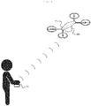
- FIG. 1 illustrates a schematic configuration of a UAV according to an embodiment of the present invention.
- the UAV includes a UAV 100, a motion control device 200, and a remote control device 300.
- a UAV 100 a UAV 100
- a motion control device 200 a motion control device 200
- a remote control device 300 a remote control device 300.
- respective components will be described in detail with regard to the functions thereof.
- respective components and the functions thereof will be described in detail.
- the UAV 100 means an aircraft without a human pilot aboard, the motion of which can be remotely controlled from the ground.
- a quadrotor a drone having four rotors, is illustrated as an example of the UAV 100.
- the present invention is not limited thereto but the UAV 100 according to the present invention may be embodied in a variety of forms.
- the motion control device 200 is attached to one surface, for example, the bottom of the UAV 100.
- the motion control device 200 is a device for controlling the motion of the UAV 100.
- the motion control device 200 may control the motion of the UAV 100 based on a control command transmitted by the remote control device 300.
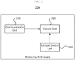
- FIG. 2 illustrates a schematic configuration of the motion control device 200 according to an embodiment of the present invention.
- the motion control device 200 includes a communication unit 210, an altitude sensor unit 220, and a control unit 230.
- the communication unit 210 receives a control command transmitted by the remote control device 300.
- the communication unit 210 may perform communications using a short-rage communications module, such as Wi-Fi, a long-range communications module, such as a radio frequency (RF) module.
- a short-rage communications module such as Wi-Fi
- a long-range communications module such as a radio frequency (RF) module.
- RF radio frequency
- the altitude sensor unit 220 measures the altitude of the UAV 100, which is necessary for takeoff or hovering.
- the altitude sensor unit 220 may be LeddarOne.
- the hovering of the UAV 100 may be performed by controlling the throttle value of a motor; however, when an altitude sensor is not used, a small change in the throttle value may cause a significant change in the altitude.
- an ultrasonic sensor has been used in the related art, it is difficult to accurately measure the altitude, since diffuse reflection may occur when the ground surface is not flat.
- the present invention can reliably control the takeoff or hovering using LeddarOne as the altitude sensor unit 220.
- the control unit 230 calculates a control value for controlling the motion of the UAV 100 based on the control command received by the communication unit 210 and the altitude value measured by the altitude sensor unit 220.
- the control unit 230 may include Raspberry Pi and Pixhack.
- Raspberry Pi is a microcomputer outputting a control valve by receiving the control command received by the communication unit 210.
- Pixhack is a flight controller including an accelerometer, a magnetometer, and a gyroscope (9-axis sensor).
- the control command may be a quaternion value, while the control value may be an Euler angle value.
- Pixhack may control the motion of the UAV 100 based on Euler angle values.
- the remote control device 300 is a device for remotely controlling the motion of the UAV 100.
- the remote control device 300 generates a control command for controlling the motion of the UAV 100, as described above, and transmits the control command to the motion control device 200.
- the remote control device 300 may be carried by (e.g. held by or attached to) a user.
- the remote control device 300 may be attached to a hand, in particular, to the palm, of the user.
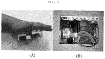
- FIGS. 3A and 3B illustrate the shape and size of a prototype of the remote control device 300, attached to the palm of the user.
- the remote control device 300 will be described as being attached to the palm of the user, as illustrated in FIG. 3A . Specifically, the remote control device 300 will be described that the top surface thereof is in contact with the palm of the user and the bottom surface thereof faces toward the ground.
- the remote control device 300 may generate a control command for controlling the motion of the UAV 100 by measuring the pose of the hand of the user using at least one sensor. More particularly, the remote control device 300 may generate the control command based on the pose of the remote control device 300 attached to the hand of the user.
- the front portion of the remote control device 300 may be inclined forwardly, thereby causing the UAV 100 to move forwardly.
- the remote control device 300 when the hand of the user are twisted to the left, with the remote control device 300 being attached to the palm of the hand of the user, the remote control device 300 is inclined to the left, thereby causing the UAV 100 to move to the left.
- the remote control device 300 when the hand of the user are twisted to the right, with the remote control device 300 being attached to the palm of the hand of the user, the remote control device 300 is inclined to the right, thereby causing the UAV 100 to move to the right.
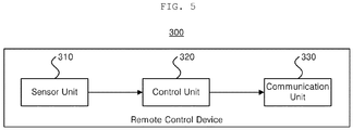
- the remote control device 300 according to an embodiment of the present invention will be described in more detail with reference to FIG. 5 .
- FIG. 5 illustrates a schematic configuration of the remote control device 300 according to an embodiment of the present invention.
- the remote control device 300 includes a sensor unit 310, a control unit 320, and a communication unit 330.
- the remote control device 300 may be implemented as a smartphone including both a processor and a communication module.
- a smartphone including both a processor and a communication module.
- the sensor unit 310 generates sensing data by sensing the motion (pose) of the hand of the user, in particular, the motion of the remote control device 300 attached to the hand of the user.
- the sensor unit 310 includes at least one sensor.
- the sensor unit 310 may be MPU-6050, i.e. a 6-axis sensor including a gyroscope and an accelerometer.
- the sensor unit 310 is not limited to the 6-axis sensor but may be a 9-axis sensor including an accelerometer, a magnetometer, and a gyroscope.
- the sensor unit 310 will be mainly described hereinafter as being a 6-axis sensor, the sensor unit 310 will also be described as being a 9-axis sensor, such that the sensor unit can control not only the direction of the motion but also the speed of the motion.
- the sensing data may be roll data, pitch data, and z-axis gravity data regarding the motion of the remote control device 300.
- the control unit 320 generates a control command for controlling the motion of the UAV 100 based on the sensing data.
- the control unit 320 may include Raspberry Pi.
- the communication unit 330 transmits the generated control command to the motion control device 200.
- the control unit 320 may determine the direction of inclination (or the direction of twisting) of the remote control device 300 using the sensing data, and may generate a control command for controlling the motion of the UAV 100 based on the determined direction of inclination.
- a plurality of directions of inclination may be used to define poses of the remote control device 300 and to indicate directions in which the remote control device 300 is inclined or twisted. This is the same as described above with reference to FIG. 3 .
- the determined direction of inclination may be one of the plurality of predetermined directions of inclination.
- the plurality of directions of inclination may be matched to the sensing data, respectively, via learning on the sensing data.
- the control unit 210 may determine a direction of inclination, among the plurality of directions of inclination set during learning, to which the generated sensing data correspond.
- the plurality of directions of inclination may include x number of directions of inclination A (where x is an integer equal to or greater than 2) categorized as a state in which the top surface of the remote control device 300 faces upwardly (i.e. the back of the hand of the user faces upwardly) and y number of directions of inclination B (where y is an integer equal to or greater than 2) categorized as a state in which the bottom surface of the remote control device 300 faces upwardly (i.e. the palm of the hand of the user faces upwardly).
- the x number of directions of inclination A correspond to the directions in which the remote control device 300 is inclined upwardly or downwardly of the x number of areas.
- the y number of directions of inclination B correspond to the directions in which the remote control device 300 is inclined upwardly or downwardly of the y number of areas.
- the control unit 320 may calculate a direction group of inclination of the remote control device 300 based on the sensing data, and may generate a control command by further using the determined direction group of inclination together with the direction of inclination of the remote control device 300.
- the direction group of inclination is obtained by grouping two or more directions of inclination among the plurality of directions of inclination, and like the direction of inclination, is used to determining the direction in which the remote control device 300 is inclined.
- the direction groups of inclination are used to determine a direction of inclination intended by the user, rather than a more accurate direction of inclination. This is used to reduce noise and generate an accurate control command.
- the determined direction groups of inclination may be one direction group of inclination among the plurality of predetermined direction groups of inclination.
- the plurality of direction groups of inclination may be matched to the sensing data, respectively, via learning on the sensing data.
- the control unit 210 may determine a direction group of inclination, among the plurality of direction groups of inclination set during learning, to which the generated sensing data correspond.
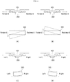
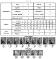
- FIGS. 6A to 6C illustrate an example of hand pose areas for defining a plurality of hand poses according to an embodiment of the present invention, by which directions of inclination and direction groups of inclination are determined.
- the hand of the user corresponds to the remote control device 300
- the back of the hand of the user corresponds to the top surface of the remote control device 300
- the palm of the hand of the user corresponds to the bottom surface of the remote control device 300.
- the top surface of the remote control device 300 will be assumed to be the back of the hand
- the bottom surface of the remote control device 300 will be assumed to be the palm of the hand.
- the back of the hand of the user is divided into nine areas that do not overlap each other, thereby forming a 3x3 matrix. All of the nine areas are used to define nine directions of inclination A.
- the nine directions of inclination A correspond to the directions in which the back of the hand is inclined downwardly of the nine areas (i.e. the nine areas A), respectively.
- one direction matched to area 1, among the nine directions of inclination A corresponds to a position in which the back of the hand of the user is inclined in the direction of area 1.
- the nine directions of inclination A may be defined as directions in which the nine areas are inclined upwardly, respectively.
- x number of areas include a direction corresponding to a position in which the remote control device 300 remains horizontal ((5), the direction of inclination 0).
- the palm of the hand of the user is divided into nine areas that do not overlap each other, thereby forming a 3x3 matrix.
- Five areas of the nine areas are used to define five directions of inclination B.
- the five directions of inclination B correspond to the directions in which the palm of the hand is inclined downwardly in the five areas of the nine areas (i.e. the five areas B).
- the five directions of inclination B may also be defined as directions in which the five areas are inclined upwardly, respectively.
- y number of areas include a direction corresponding to a position in which the remote control device 300 remains horizontal (10 in which an angle of inclination is 0°).
- FIG. 6C illustrates four direction groups of inclination.
- the four direction groups of inclination may be defined based on the nine areas A of the back of the hand of the user, as described with reference to FIG. 6A .
- the four direction groups include a first direction group of inclination 15 with respect to the forward direction, a second direction group of inclination 16 with respect to the backward direction, a third direction group of inclination 17 with respect to the left, and a fourth direction group of inclination 18 with respect to the right.
- the first direction group of inclination includes three directions of inclination A, corresponding to three areas in the forward direction among the nine areas, i.e. areas 1, 2, and 3.
- the second direction group of inclination includes three directions of inclination A, corresponding to three areas in the backward direction among the nine areas, i.e. areas 7, 8, and 9.
- the third direction group of inclination includes three directions of inclination A, corresponding to three areas in the left among the nine areas, i.e. areas 1, 4, and 7.
- the fourth direction group of inclination includes three directions of inclination A, corresponding to three areas in the right among the nine areas, i.e. areas 3, 6, and 9.
- the x number of directions of inclination A according to the top surface of the remote control device 300 include a plurality of directions of inclination A1 with respect to the forward direction, a plurality of directions of inclination A2 with respect to the backward direction, a plurality of directions of inclination A3 with respect to the left, and a plurality of directions of inclination A4 with respect to the right.
- the first direction group of inclination is obtained by grouping the plurality of directions of inclination A1
- the second direction group of inclination is obtained by grouping the plurality of directions of inclination A2
- the third direction group of inclination is obtained by grouping the plurality of directions of inclination A3
- the fourth direction group of inclination is obtained by grouping the plurality of directions of inclination A4.
- FIG. 7 illustrates a concept of the operation of the remote control device 300 according to an embodiment of the present invention.
- the sensor unit 310 generates roll data, pitch data, and z-axis gravity data regarding the hand of the user by sensing the motion of the hand of the user, and transmits the generated data to the control unit 320.
- the sensor unit 310 continuously senses the roll data, the pitch data, and the z-axis gravity data.
- the control unit 320 generates a control command by receiving the roll data, the pitch data, and the z-axis gravity data, which are continuously sensed.
- the control unit 320 includes a first neural network Neural Network 1 and a second neural network Neural Network 2.
- the first neural network is comprised of three input data, thirty-two hidden data, and fourteen output data.
- the first neural network receives the roll data, the pitch data, and the z-axis gravity data, which are continuously sensed, outputs probability values of fourteen areas, and thereby, determines one direction of inclination among fourteen directions of inclination.
- the first neural network outputs the probability values of the fourteen areas, based on the continuously-input sensing data.
- the probability value of area 1 among the fourteen areas is the maximum
- the first neural network determines the remote control device 300 to be inclined in a direction of inclination, corresponding to area 1, among the fourteen directions of inclination.
- the second neural network is comprised of eighteen input data, sixty-four first hidden data, thirty-two hidden data, and fourteen output data.
- Fourteen input data among the eighteen input data correspond to the above-determined directions of inclination.
- the value of first input data among the fourteen input data may be "1," while the value of second to fourteenth input data among the fourteen input data may be "0.”
- the remaining four input data among the fourteen input data are input, including the four direction groups of inclination.
- one direction group of inclination is determined among the four direction groups of inclination, based on the continuously-input sensing data, and then is input to the second neural network. For example, when the determined direction group of inclination is the first direction group of inclination, the input value of the fifteenth input data may be "1," and the input value of the eighteenth input data may be "0.”
- a majority of the sensing data may be distributed in area 1, a little amount of sensing data may be distributed in areas 2 and 3, and no sensing data may be distributed in the remaining areas.
- the continuously-input sensing data may be uniformly distributed in areas 1, 4, and 7, and no sensing data may be distributed in the remaining areas. In this case, it is determined that the remote control device 300 is inclined in the third direction group of inclination corresponding to the left, among the four direction groups of inclination.
- the second neural network generates a control command via the fourteen output data.
- the control command may include a first mode control command for controlling the direction of the movement of the UAV 100 and a second mode control command for controlling the UAV 100 to move along a predetermined geometric flight path.
- the first mode control command may include an ascending command Up, a descending command Down, a right movement command Right, a left movement command Left, a forward movement command Forward, a backward movement command Backward, a forward-right movement command Forward-Right, a forward-left movement command Forward-Left, a backward-right movement command Backward-Right, and a backward-left movement command Backward-Left.
- the second mode control command may include a circular movement command Circle, a spiral movement command Spiral, a triangular movement command Triangle, and a quadrangular movement command Square.
- FIG. 8 illustrates exemplary poses of a hand used to generate geometric flight path commands.
- the control unit 320 may perform a mode change using at least one direction of inclination among the fourteen directions of inclination.
- the control unit 320 may generate one mode control command of the first mode control command and the second mode control command, in response to the mode change. For example, when the remote control device 300 is inclined in a direction of inclination corresponding to area ⁇ , the control unit 320 may be changed to the first mode. When the remote control device 300 is inclined in a direction of inclination corresponding to area 14, the control unit 320 may be changed to the second mode.
- the remote control device 300 may adjust the size of the flight path (such that the flight path is, for example, to be a smaller circle, a middle circle, and a larger circle).
- the remote control device 300 may use a scale factor. That is, the control unit 320 may calculate a scale factor, based on sensing data sensed by the gyroscope of the sensor unit 310 and a period of time for generating a hand gesture.
- the geometric flight path control process of the UAV 100 may be performed after the change to the second mode is undertaken, in a position in which the top surface of the remote control device 300 faces upwardly.
- the scale may be adjusted using a period of time for returning to area (5), i.e. a horizontal position (reference position), is performed after sensing data are sequentially input into the adjacent areas corresponding thereto among the nine areas in FIG. 6A , for example, in the sequence of areas 5, 1, 2, 3, 6, 9, 8, 7, and 4.
- a horizontal position reference position
- the UAV 100 is controlled to move along a greater path.
- the motion of the UAV 100 is controlled by determining the direction of inclination of the remote control device 300.
- the control unit 230 may determine the speed of movement using a period of time for which the direction of inclination determined based on the sensing data is maintained.
- control unit 230 determines a period of time for which the determined direction of inclination is to be maintained.
- the speed of the UAV 100 may be comprised of a plurality of speeds sections.
- the UAV 100 may be determined to move at a speed corresponding to a specific speed section among the plurality of speed sections.
- the UAV 100 may move at a speed V1 in a direction of movement corresponding to the determined direction of inclination. Afterwards, when the direction of inclination is maintained for a period of time T2, the UAV 100 may move at a speed V2 corresponding to the period of time T1 or T2.
- V2 is a speed faster than V1.
- the speed of movement of the UAV 100 may be controlled using an angle in the direction of inclination.
- the angle in the direction of inclination may be determined when a nine-axis sensor is used instead of a six-axis sensor.
- the direction indicated by the front portion of the UAV 100 may differ from the direction at an initial point in time of the flight along the geometric path.
- control unit 230 stores the position of the UAV 100 at a point in time at which a change to the second mode was undertaken (the initial point in time).
- the position at the initial point in time may be information regarding the direction indicated by the front portion of the UAV 100.
- control unit 230 may generate a control command to correct the position of the UAV 100.
- the motion of the UAV 100 is controlled using the remote control device 300 attached to the hand of the user, it is possible to intuitively control the motion of the UAV 100. In addition, it is possible to control the UAV 100 to move along a geometric flight path without additional equipment.
- FIG. 9 illustrates a flowchart of a remote control method for a UAV according to an embodiment of the present invention.
- the remote control method may be performed by a device carried by the user and including a processor.
- a processor may be included in the remote control method.
- step 910 sensing data generated by sensing a motion of the device using at least one sensor is input.
- step 920 a direction of inclination of the device is determined based on the sensing data.
- step 930 a control command for controlling the motion of the UAV is generated based on the determined direction of inclination.
- step 940 the generated control command is transmitted to the UAV.
- a direction group of inclination may be further calculated based on the sensing data, and in step 930, the control command may be generated further using the calculated direction group of inclination.
- the remote control method for a UAV has been described so far.
- the configuration of the remote control device 300 described earlier with reference to FIGS. 1 to 8 , may be applied to the remote control method, and specific descriptions thereof will be omitted.
- Computer readable media may include independently or associatively program instructions, data files, data structures, and so on.
- Program instructions recorded in the media may be specially designed and configured for the present invention, or may be generally known by those skilled in the computer software art.
- Computer readable recording media may include magnetic media such as hard disks and floppy disks, optical media such as CD-ROM and DVD, magneto-optical media such as floptical disks, and hardware units, such as ROM, RAM, flash memory, and so on, which are intentionally formed to store and perform program instructions.
- Program instructions may include high-class language codes executable by computers using interpreters, as well as machine language codes likely made by compilers.
- the hardware units may be configured to function as one or more software modules for performing operations according to embodiments of the present disclosure, and vice versa.
Landscapes
- Engineering & Computer Science (AREA)
- Theoretical Computer Science (AREA)
- Physics & Mathematics (AREA)
- General Engineering & Computer Science (AREA)
- General Physics & Mathematics (AREA)
- Human Computer Interaction (AREA)
- Aviation & Aerospace Engineering (AREA)
- Remote Sensing (AREA)
- Radar, Positioning & Navigation (AREA)
- Automation & Control Theory (AREA)
- Mathematical Physics (AREA)
- Computing Systems (AREA)
- General Health & Medical Sciences (AREA)
- Computer Vision & Pattern Recognition (AREA)
- Health & Medical Sciences (AREA)
- Psychiatry (AREA)
- Social Psychology (AREA)
- Multimedia (AREA)
- Control Of Position, Course, Altitude, Or Attitude Of Moving Bodies (AREA)
- Selective Calling Equipment (AREA)
- Toys (AREA)
Applications Claiming Priority (2)
| Application Number | Priority Date | Filing Date | Title |
|---|---|---|---|
| KR1020170172512A KR101887314B1 (ko) | 2017-12-14 | 2017-12-14 | 무인 항공기의 원격 제어 장치 및 방법과, 무인 항공기에 부착되는 움직임 제어 장치 |
| KR1020170178178A KR102019569B1 (ko) | 2017-12-22 | 2017-12-22 | 무인 항공기의 원격 제어 장치 및 방법 |
Publications (2)
| Publication Number | Publication Date |
|---|---|
| EP3499332A2 true EP3499332A2 (de) | 2019-06-19 |
| EP3499332A3 EP3499332A3 (de) | 2019-07-31 |
Family
ID=64476943
Family Applications (1)
| Application Number | Title | Priority Date | Filing Date |
|---|---|---|---|
| EP18208079.6A Withdrawn EP3499332A3 (de) | 2017-12-14 | 2018-11-23 | Fernsteuerungsvorrichtung und verfahren für ein unbemanntes luftfahrzeug und an einem unbemannten luftfahrzeug angebrachte bewegungssteuerungsvorrichtung |
Country Status (3)
| Country | Link |
|---|---|
| US (1) | US10545495B2 (de) |
| EP (1) | EP3499332A3 (de) |
| CN (1) | CN109960276B (de) |
Families Citing this family (5)
| Publication number | Priority date | Publication date | Assignee | Title |
|---|---|---|---|---|
| US12045050B2 (en) * | 2018-01-12 | 2024-07-23 | Superior Marine LLC | Gesturing for control input for a vehicle |
| KR102032067B1 (ko) * | 2018-12-05 | 2019-10-14 | 세종대학교산학협력단 | 강화학습 기반 무인 항공기 원격 제어 방법 및 장치 |
| JP7392622B2 (ja) * | 2020-09-30 | 2023-12-06 | トヨタ自動車株式会社 | 無人航空機の制御方法、サーバ、及び、無人航空機 |
| CN114641747A (zh) * | 2020-12-25 | 2022-06-17 | 深圳市大疆创新科技有限公司 | 可移动平台的控制方法、体感遥控器及存储介质 |
| TWI815707B (zh) | 2022-10-21 | 2023-09-11 | 仁寶電腦工業股份有限公司 | 基於壓力控制無人機的系統和方法 |
Citations (1)
| Publication number | Priority date | Publication date | Assignee | Title |
|---|---|---|---|---|
| KR20170090603A (ko) | 2016-01-29 | 2017-08-08 | 아주대학교산학협력단 | 손의 움직임 인식을 이용한 드론 제어 시스템 및 방법 |
Family Cites Families (16)
| Publication number | Priority date | Publication date | Assignee | Title |
|---|---|---|---|---|
| FR2809026B1 (fr) * | 2000-05-18 | 2003-05-16 | Philippe Louvel | Soucoupe volante electrique, pilotee et alimentee a distance |
| JP4532318B2 (ja) * | 2005-03-25 | 2010-08-25 | ヤマハ発動機株式会社 | 無人ヘリコプタ |
| TWI459234B (zh) * | 2010-07-14 | 2014-11-01 | Hon Hai Prec Ind Co Ltd | 手持裝置及利用其控制無人飛行載具的方法 |
| US20140008496A1 (en) * | 2012-07-05 | 2014-01-09 | Zhou Ye | Using handheld device to control flying object |
| CN103885404B (zh) * | 2014-03-06 | 2016-08-17 | 青岛罗博飞海洋技术有限公司 | 水下机器人四螺旋桨推进器控制方法 |
| KR101609553B1 (ko) | 2014-07-16 | 2016-04-06 | 고려대학교 산학협력단 | 3차원 동작인식 정보입력 장치 및 방법, 이를 구현하기 위한 프로그램이 저장된 기록매체 |
| EP3065042B1 (de) * | 2015-02-13 | 2018-11-07 | LG Electronics Inc. | Tragbares endgerät und verfahren zur steuerung davon |
| US9365290B1 (en) * | 2015-08-27 | 2016-06-14 | Martin Uav, Llc | Vertical take off aircraft |
| KR20170035547A (ko) | 2015-09-23 | 2017-03-31 | 엘지이노텍 주식회사 | 원격 제어장치, 원격 제어방법 및 원격 제어시스템 |
| CN205139708U (zh) * | 2015-10-28 | 2016-04-06 | 上海顺砾智能科技有限公司 | 一种无人机的动作识别远程控制装置 |
| US10133271B2 (en) * | 2016-03-25 | 2018-11-20 | Qualcomm Incorporated | Multi-axis controlller |
| CN105955302A (zh) * | 2016-06-20 | 2016-09-21 | 武汉理工大学 | 一种多旋翼无人机环境自主监测控制系统及方法 |
| CN106406331A (zh) * | 2016-11-25 | 2017-02-15 | 广州亿航智能技术有限公司 | 一种飞行器的飞行控制方法、装置和系统 |
| CN106774945A (zh) * | 2017-01-24 | 2017-05-31 | 腾讯科技(深圳)有限公司 | 一种飞行器飞行控制方法、装置、飞行器及系统 |
| CN106945835A (zh) * | 2017-03-09 | 2017-07-14 | 长沙开雅电子科技有限公司 | 一种无人飞行器 |
| KR101887314B1 (ko) | 2017-12-14 | 2018-08-09 | 세종대학교산학협력단 | 무인 항공기의 원격 제어 장치 및 방법과, 무인 항공기에 부착되는 움직임 제어 장치 |
-
2017
- 2017-12-28 US US15/857,204 patent/US10545495B2/en active Active
-
2018
- 2018-11-23 EP EP18208079.6A patent/EP3499332A3/de not_active Withdrawn
- 2018-11-28 CN CN201811438905.1A patent/CN109960276B/zh not_active Expired - Fee Related
Patent Citations (1)
| Publication number | Priority date | Publication date | Assignee | Title |
|---|---|---|---|---|
| KR20170090603A (ko) | 2016-01-29 | 2017-08-08 | 아주대학교산학협력단 | 손의 움직임 인식을 이용한 드론 제어 시스템 및 방법 |
Also Published As
| Publication number | Publication date |
|---|---|
| EP3499332A3 (de) | 2019-07-31 |
| US20190187692A1 (en) | 2019-06-20 |
| CN109960276A (zh) | 2019-07-02 |
| US10545495B2 (en) | 2020-01-28 |
| CN109960276B (zh) | 2022-08-30 |
Similar Documents
| Publication | Publication Date | Title |
|---|---|---|
| EP3499332A2 (de) | Fernsteuerungsvorrichtung und verfahren für ein unbemanntes luftfahrzeug und an einem unbemannten luftfahrzeug angebrachte bewegungssteuerungsvorrichtung | |
| CN114206558B (zh) | 基于来自远程客户端设备的输入的高效机器人控制 | |
| TWI616802B (zh) | 觸控顯示裝置、觸控顯示方法及無人機 | |
| CN105549604B (zh) | 飞行器操控方法和装置 | |
| Spasojevic et al. | Perception-aware time optimal path parameterization for quadrotors | |
| CN110069071A (zh) | 无人机导航方法与装置、存储介质、电子设备 | |
| EP1067452A2 (de) | Dreidimensionaler Pfeil | |
| TWI426428B (zh) | 手持裝置及利用其控制無人飛行載具的方法 | |
| CN106527479A (zh) | 一种无人机的控制方法及装置 | |
| US20190212807A1 (en) | Tracking Torso Leaning to Generate Inputs for Computer Systems | |
| US11511842B2 (en) | Miniature autonomous robotic blimp | |
| US12462694B2 (en) | Route planning device, route planning method, and computer program product | |
| Barber et al. | Visual and tactile interfaces for bi-directional human robot communication | |
| KR101887314B1 (ko) | 무인 항공기의 원격 제어 장치 및 방법과, 무인 항공기에 부착되는 움직임 제어 장치 | |
| CN111290574B (zh) | 一种利用手势控制无人机的方法,设备及可读存储介质 | |
| CN114815880A (zh) | 基于手柄的无人机控制方法、装置、设备与可读存储介质 | |
| KR102019569B1 (ko) | 무인 항공기의 원격 제어 장치 및 방법 | |
| Sandru et al. | Automatic control of a quadcopter, ar. drone, using a smart glove | |
| WO2017185521A1 (zh) | 基于移动终端的无人机控制方法和装置 | |
| Lu et al. | Gesture control of quadcopter for a stable flight | |
| CN204667193U (zh) | 多旋翼飞行器 | |
| CN106527482A (zh) | 一种无人机飞行控制方法和装置 | |
| US20260062108A1 (en) | System and a method therein for steering control stabilization of a marine vessel | |
| Chen et al. | Development of Intelligent Drone Remote Control System Based on Internet of Things. | |
| Wang | Advanced guidance and navigation of small UAVs under GPS-denied environment with experimental validations |
Legal Events
| Date | Code | Title | Description |
|---|---|---|---|
| PUAI | Public reference made under article 153(3) epc to a published international application that has entered the european phase |
Free format text: ORIGINAL CODE: 0009012 |
|
| 17P | Request for examination filed |
Effective date: 20181217 |
|
| AK | Designated contracting states |
Kind code of ref document: A2 Designated state(s): AL AT BE BG CH CY CZ DE DK EE ES FI FR GB GR HR HU IE IS IT LI LT LU LV MC MK MT NL NO PL PT RO RS SE SI SK SM TR |
|
| AX | Request for extension of the european patent |
Extension state: BA ME |
|
| PUAL | Search report despatched |
Free format text: ORIGINAL CODE: 0009013 |
|
| AK | Designated contracting states |
Kind code of ref document: A3 Designated state(s): AL AT BE BG CH CY CZ DE DK EE ES FI FR GB GR HR HU IE IS IT LI LT LU LV MC MK MT NL NO PL PT RO RS SE SI SK SM TR |
|
| AX | Request for extension of the european patent |
Extension state: BA ME |
|
| RIC1 | Information provided on ipc code assigned before grant |
Ipc: G05D 1/00 20060101AFI20190625BHEP |
|
| STAA | Information on the status of an ep patent application or granted ep patent |
Free format text: STATUS: THE APPLICATION IS DEEMED TO BE WITHDRAWN |
|
| 18D | Application deemed to be withdrawn |
Effective date: 20200201 |