EP3500516B1 - Fass mit druckventil zum aufbewahren von bier, dessen verwendung, verfahren zum regeln des drucks im fass, fasshohlboden, modulares system zum herstellen eines fasshohlbodens und verfahren zum befuellen eines fasses - Google Patents
Fass mit druckventil zum aufbewahren von bier, dessen verwendung, verfahren zum regeln des drucks im fass, fasshohlboden, modulares system zum herstellen eines fasshohlbodens und verfahren zum befuellen eines fasses Download PDFInfo
- Publication number
- EP3500516B1 EP3500516B1 EP17772762.5A EP17772762A EP3500516B1 EP 3500516 B1 EP3500516 B1 EP 3500516B1 EP 17772762 A EP17772762 A EP 17772762A EP 3500516 B1 EP3500516 B1 EP 3500516B1
- Authority
- EP
- European Patent Office
- Prior art keywords
- pressure
- container
- chamber
- pressure valve
- filling
- Prior art date
- Legal status (The legal status is an assumption and is not a legal conclusion. Google has not performed a legal analysis and makes no representation as to the accuracy of the status listed.)
- Not-in-force
Links
Images


Classifications
-
- B—PERFORMING OPERATIONS; TRANSPORTING
- B67—OPENING, CLOSING OR CLEANING BOTTLES, JARS OR SIMILAR CONTAINERS; LIQUID HANDLING
- B67D—DISPENSING, DELIVERING OR TRANSFERRING LIQUIDS, NOT OTHERWISE PROVIDED FOR
- B67D1/00—Apparatus or devices for dispensing beverages on draught
- B67D1/04—Apparatus utilising compressed air or other gas acting directly or indirectly on beverages in storage containers
- B67D1/0412—Apparatus utilising compressed air or other gas acting directly or indirectly on beverages in storage containers the whole dispensing unit being fixed to the container
- B67D1/0437—Apparatus utilising compressed air or other gas acting directly or indirectly on beverages in storage containers the whole dispensing unit being fixed to the container comprising a gas pressure space within the container for the liquid
-
- B—PERFORMING OPERATIONS; TRANSPORTING
- B65—CONVEYING; PACKING; STORING; HANDLING THIN OR FILAMENTARY MATERIAL
- B65D—CONTAINERS FOR STORAGE OR TRANSPORT OF ARTICLES OR MATERIALS, e.g. BAGS, BARRELS, BOTTLES, BOXES, CANS, CARTONS, CRATES, DRUMS, JARS, TANKS, HOPPERS, FORWARDING CONTAINERS; ACCESSORIES, CLOSURES, OR FITTINGS THEREFOR; PACKAGING ELEMENTS; PACKAGES
- B65D83/00—Containers or packages with special means for dispensing contents
- B65D83/14—Containers for dispensing liquid or semi-liquid contents by internal gaseous pressure, i.e. aerosol containers comprising propellant
- B65D83/60—Containers for dispensing liquid or semi-liquid contents by internal gaseous pressure, i.e. aerosol containers comprising propellant with contents and propellant separated
- B65D83/673—Containers for dispensing liquid or semi-liquid contents by internal gaseous pressure, i.e. aerosol containers comprising propellant with contents and propellant separated at least a portion of the propellant being separated from the product and incrementally released by means of a pressure regulator
-
- B—PERFORMING OPERATIONS; TRANSPORTING
- B67—OPENING, CLOSING OR CLEANING BOTTLES, JARS OR SIMILAR CONTAINERS; LIQUID HANDLING
- B67D—DISPENSING, DELIVERING OR TRANSFERRING LIQUIDS, NOT OTHERWISE PROVIDED FOR
- B67D1/00—Apparatus or devices for dispensing beverages on draught
- B67D1/08—Details
- B67D1/0801—Details of beverage containers, e.g. casks, kegs
- B67D1/0802—Dip tubes
-
- B—PERFORMING OPERATIONS; TRANSPORTING
- B67—OPENING, CLOSING OR CLEANING BOTTLES, JARS OR SIMILAR CONTAINERS; LIQUID HANDLING
- B67D—DISPENSING, DELIVERING OR TRANSFERRING LIQUIDS, NOT OTHERWISE PROVIDED FOR
- B67D1/00—Apparatus or devices for dispensing beverages on draught
- B67D1/08—Details
- B67D1/12—Flow or pressure control devices or systems, e.g. valves, gas pressure control, level control in storage containers
- B67D1/1252—Gas pressure control means, e.g. for maintaining proper carbonation
-
- B—PERFORMING OPERATIONS; TRANSPORTING
- B65—CONVEYING; PACKING; STORING; HANDLING THIN OR FILAMENTARY MATERIAL
- B65D—CONTAINERS FOR STORAGE OR TRANSPORT OF ARTICLES OR MATERIALS, e.g. BAGS, BARRELS, BOTTLES, BOXES, CANS, CARTONS, CRATES, DRUMS, JARS, TANKS, HOPPERS, FORWARDING CONTAINERS; ACCESSORIES, CLOSURES, OR FITTINGS THEREFOR; PACKAGING ELEMENTS; PACKAGES
- B65D83/00—Containers or packages with special means for dispensing contents
- B65D83/14—Containers for dispensing liquid or semi-liquid contents by internal gaseous pressure, i.e. aerosol containers comprising propellant
-
- B—PERFORMING OPERATIONS; TRANSPORTING
- B67—OPENING, CLOSING OR CLEANING BOTTLES, JARS OR SIMILAR CONTAINERS; LIQUID HANDLING
- B67D—DISPENSING, DELIVERING OR TRANSFERRING LIQUIDS, NOT OTHERWISE PROVIDED FOR
- B67D1/00—Apparatus or devices for dispensing beverages on draught
- B67D1/08—Details
- B67D1/0801—Details of beverage containers, e.g. casks, kegs
- B67D2001/0822—Pressurised rigid containers, e.g. kegs, figals
- B67D2001/0824—Pressurised rigid containers, e.g. kegs, figals with dip tubes
Definitions
- the inventions relate to the technical field of packaging technology.
- an invention relates to a container, the contents of which can be conveniently removed by a consumer, in particular is under an increased internal pressure compared to the external pressure.
- another invention relates to a pressure valve for said container.
- yet another invention relates to a method of regulating pressure in a container.
- another invention relates to a hollow container bottom and a modular system for producing a hollow container bottom.
- Another invention relates to a method for filling a container.
- the container is comparatively voluminous, significantly larger than a common beverage can and the contents are a beverage that is to be tapped under pressure.
- Portable beer kegs those with a volume of less than 50 liters, in particular less than 20 liters and more than 2.5 liters, the contents of which can be tapped by consumers independently, are of particular importance in two common variants.
- a variant of such portable beer kegs can be emptied by the effect of gravitational force.
- a tap is arranged in the lower area of the outside of the container. The beer can flow out by opening the tap.
- such containers include a device that allows air from the environment to get into the interior of the container.
- Such containers are not very user-friendly, since to fill a glass with beer, the keg has to be placed on the edge of a table, for example, or the keg has to be built under in order to be able to fill the glass below the tap.
- the shelf life of the keg contents after the keg has been opened is considerably reduced by the atmospheric oxygen flowing in as the beer flows out.
- containers that include an internal pressure system. These systems keep the pressure inside above ambient pressure. This allows the tap to be arranged in the upper area of the container. A consumer typically has enough space between the lower outlet end of the tap and the level of the container to place a glass to be filled under the Hold the tap without having to specifically position the keg.
- internal pressure systems By using internal pressure systems, the shelf life of the beer after the keg has been opened can be up to more than 30 days, since no atmospheric oxygen flows into the keg while the beer is being removed.
- a beer keg system of the second variant is the specialist WO 1999/47451 (Heineken Technical Services).
- a beer keg system which comprises a pressure cartridge which is arranged in the interior of the container space filled with beer and generates an overpressure in this space.
- the pressure cartridge comprises activated carbon, as a result of which a larger amount of compressed or propellant gas can be introduced into the cartridge compared to a cartridge not provided with activated carbon without increasing the pressure in the cartridge too much.
- These cartridges are called “Carbonator" in trade and sale.
- the material of the "carbonator” is made of a different metal than the material of the wall of the beer keg. In the recycling process, this leads to mixed scrap (including material of the wall of the "carbonator” and material of the outer wall of the beer keg), which will receive more and more attention in the future to avoid it.
- U.S. 2,345,081 (Ward ) from 1944 concerns a siphon (a dispenser for mineral water).
- This has a bottom construction with a pressure space for the intermediate storage of a gas at a pressure well above atmospheric pressure, which can be drained in a controlled manner via a valve construction VB into a chamber (a filling space LC) filled with liquid (mineral water, but not beer).
- the pressure chamber has a wall bulging inwards (into the pressure chamber) on both axial ends.
- a high-pressure cartridge GB is plugged into the lower end of the siphon (as a container) (screwed on with a sleeve), so that the siphon is no longer able to stand on a flat floor (or level table).
- a container according to the preamble of claim 1 is from DE 20 2005 017 072 U1 known.
- the invention relates to a container according to claim 1 and a method according to claim 13.
- Aus completelyungsbeinot make it possible to provide a system that can be manufactured inexpensively by a consumer with a high level of ease of use and provides high flexibility with regard to the propellant gas selection (pressure and type of gas) and achieves a long shelf life of the contents, even after the container has been opened.
- a claimed container for storing a liquid comprises a filling space (also: filling space), a pressure space and a pressure valve.
- the filling space is formed by a container bottom, a container wall and a container top and a first pressure prevails in the filling space.
- the pressure chamber is formed by the container base and a pressure chamber base and a second pressure prevails in the pressure chamber.
- the pressure valve is connected to the container base and the pressure chamber base. When the pressure valve is open, the pressure valve connects the filling space and the pressure space in a fluid-communicating manner. In the closed state of the pressure valve, the pressure valve separates the filling space and the pressure space from one another in a fluid-tight manner.
- the second pressure in the pressure chamber is greater than the ambient pressure and / or the pressure in the filling chamber, forces act on the container base and on the pressure chamber base, each of which is directed outwards from the inside of the pressure chamber base.
- the pressure valve is connected to the container base and to the pressure chamber base, some of the forces can be absorbed by the pressure valve.
- Fluid-communicating means that a fluid exchange between two spaces (for example filling space and pressure space) is possible, in particular quickly and not slowly.
- Fluid-tight means that practically no fluid exchange can take place between two rooms; The person skilled in the art understands that perfect sealing of two spaces without any fluid exchange or fluid flow taking place is practically impossible. Parasitic flow or exchange is always present, so it is not a practically significant exchange. A marginal fluid flow or fluid exchange will also take place between two fluid-tightly separated spaces, the pressure difference between the two spaces having an influence on the amount of the parasitically exchanged fluid per unit of time.
- the fluid exchange in the closed state of the pressure valve is very much less than the fluid exchange when the pressure valve is open, that is to say in fluid communication.
- the container base and the pressure chamber base can each have a recess. The pressure valve can engage in these recesses, whereby a force resulting from a pressure difference between the pressure chamber and the filling chamber and the pressure chamber and the environment can be absorbed.
- the pressure valve can have a pressure valve body.
- a projection can be arranged at the upper and lower end of the pressure valve, the upper and the lower projection each projecting at least partially around the circumference in the r-direction over at least a radial part of the pressure valve body.
- the projections (top and bottom) can be formed over the entire circumference of the pressure valve or can be formed over part of the circumference. It is also possible to form a plurality of projections per axial end of the pressure valve (top and bottom), it being possible for each of the projections to be partially circumferential.
- the projection at the upper end of the pressure valve preferably contacts the upper side of the container bottom and the projection at the lower end of the pressure valve contacts the lower one Side of the pressure chamber floor.
- the projections of the pressure valve can comprise a sealing element.
- a sealing element can be arranged per side of the pressure valve or only one sealing element or sealing elements can be arranged on a projection or on projections on one side of the pressure valve.
- the container may include an outlet conduit having one end and another end.
- One end of the outlet line can lie in the filling space.
- a consumer can remove (tap) a content from the filling space via the outlet line.
- the interior of the container bottom can be arched or designed entirely in the shape of a dome, in the direction of the filling space. At least one section of the container bottom is therefore curved.
- the shortest distance can be determined by choosing a point on the pressure chamber floor which has the smallest distance to the end of the outlet line located in the filling chamber.
- the distance between the described end of the inner section of the outlet line and the pressure chamber floor can be smaller (smaller) than a distance between the described end of the outlet line and the apex of the curved floor section. If there is already a recess there (for the pressure valve), it is the edge of the recess in the container bottom, with an apex being extrapolated here too (in the center of the recess).
- the container bottom is at least partially curved or completely dome-shaped and has a central opening, namely at a point on the container bottom at which the apex would be on the container bottom if the container bottom did not have the opening or the opening at another Place would be, the container bottom has an apex.
- the vertex is to be determined by extrapolation and is at one Located where the apex would be on the container bottom if there is no opening in the container bottom or the opening is in another location.
- the (almost entire) contents of the container can be advantageously withdrawn via the outlet line, especially if the content is a liquid that tends to foam, e.g. beer, and the fill level in the filling chamber is low.
- the lowest point (or the deepest circumferential channel) of the filling space is below the highest point of the container bottom.
- the first is radially outside, the second is in the center.
- the end of the outlet line protrudes into the channel.
- a z-axis can also be formed by the container.
- the z-axis extends therein from or through the pressure chamber floor in the direction of the container top. Accordingly, there is a lower numerical value on the z-axis for the pressure chamber floor than for the upper side of the container.
- the end of the outlet line cannot be arranged above (that is, at the same level or below) the pressure valve with regard to the z-axis.
- the container base can be curved or dome-shaped. At least one section of the container bottom is arched or dome-shaped.
- One end of the outlet line, especially one end that lies in the filling space, cannot lie above (the same height or below) the apex or the edge of an opening in the container bottom.
- the above to determine the The vertex is also used for this container.
- the configuration in turn has the advantage of reduced removal of foam from the filling space.
- the pressure in the pressure chamber can be at least 1 bar higher than in the filling chamber.
- the pressure in the pressure chamber is preferably at least 2 bar, particularly preferably at least 3 bar, greater than the pressure in the filling chamber.
- any pressure valve disclosed herein can be a control valve.
- the pressure chamber can be filled with a propellant gas.
- the propellant gas is preferably carbon dioxide (CO 2 ), nitrogen (N 2 ), laughing gas (N 2 O) or mixtures of the gases.
- the pressure in the pressure chamber is preferably between 5 bar (0.5 MPa) and 35 bar (3.5 MPa), specifically the pressure between 5 bar and 30 bar, more particularly between 8 bar and 25 bar (claim 10).
- the pressure in the pressure space is also determined by the volume of the pressure space, so that with a larger volume of the pressure space and the presence of a constant amount of substance, the pressure can be lower or with a larger volume of the pressure space the pressure can be higher.
- the pressure in the filling chamber can be lower than the pressure in the pressure chamber.
- the pressure in the filling chamber can be between 1.2 bar (0.12 MPa) and 7 bar (0.7 MPa), more specifically between 1.5 bar and 6 bar, even more specifically between 1.7 and 5 bar.
- the volume of the pressure chamber can be between 0.1 L and 5 L, specifically between 0.1 L and 3 L, more specifically between 0.5 L and 2.5 L, even more specifically between 0.5 L and 1.5 L.
- the volume of the filling space can be between 1 L and 25 L, especially between 2 L and 20 L (claim 11).
- the filling space preferably has a volume which allows it to hold 2 L, 3 L, 5 L or 20 L of a liquid, so that there is preferably a gas-filled area of at least 0.05 L in addition to the liquid in the filling space.
- the pressure space cannot include a filler.
- a filler is a component that is typically in a solid aggregate state under ambient conditions and allows the absorption of a certain amount of a substance. The increase in pressure in the space in which the filler is introduced is less due to the introduction of the substance, compared with the introduction of the same amount of substance into the same room without filler.
- the vapor pressure of the propellant gas or the propellant gas mixture can be above the pressure of the pressure chamber, especially down to a temperature of -5 ° C.
- the propellant gas or propellant gas mixture in the pressure chamber is largely in gaseous form, whereby the person skilled in the art is aware that a (very) small proportion of the propellant gas or propellant gas mixture is also present in liquid form in this state (see surface energy or surface tension effects on strong curved surfaces).
- the presence of the propellant gas largely as a gas improves the safety of the container compared to a propellant gas filling which is present to a considerable extent as a liquid. If the propellant gas is liquid to a considerable extent at room temperature and below, heating the container (e.g. if a consumer exposes the container to intense solar radiation and / or high temperature for a long period of time) can lead to a phase change from the liquid to the gaseous phase, which can increase the pressure considerably. This can lead to failure of the pressure chamber wall material. In addition, such a phase change pressure rise is problematic when a consumer first uses the container.
- the arrangement of the pressure valve in the container allows, if there should be a very high pressure increase in the pressure chamber, that the overpressure is released to the environment via the pressure chamber floor, possibly with destruction of the pressure valve. This is advantageous compared to the state of the art, since in the case of containers of the state of the art usually the entire container will burst if a critical pressure is exceeded.
- the container bottom is preferably arched upwards at least in the radial inner region or is formed in the shape of a dome overall, perhaps with the exception of the outer edge region.
- the container bottom is curved in the z-direction towards the interior of the container (towards the filling space).
- the apex or the edge of a recess in the container bottom protrudes in the direction of the filling volume for the liquid.
- a curvature of the container bottom allows a space to be formed from a total of only two components (here the container bottom and the pressure chamber bottom). In addition, there is an improved force absorption of the curved component compared to a non-curved component. Furthermore, a container bottom that is curved inwards (towards the filling space) allows a filled container to be emptied further, since with a constant residual filling quantity in the edge area of the filling space of the container, a container bottom that is flat or curved in another z-direction results in an increased filling height (with a smaller cross-sectional area ), see U.S. 2,345,081 (Ward ), addressed and explained at the beginning.
- the pressure chamber floor can be designed to be essentially planar; specifically, the pressure chamber floor is designed essentially parallel to the top of the container.
- the "essentially” allows a deviation from planarity and parallelism by 10%. This is sufficient for mounting a metallic ground sleeve, which runs between the two recesses in the floors and is connected to them in a sealing manner.
- the deviation from planarity can thus be used to apply a tension to the ground sleeve, the container bottom being deflected slightly upwards and the ground sleeve being held at the top with a tension.
- the ground sleeve relieves the actual functional valve of axial forces, which functional valve can be pushed into the already mounted ground sleeve and is mounted in it in an axially immovable manner.
- the pressure chamber floor can be designed in such a way that when the container is standing upright on a flat surface, the pressure chamber floor does not contact the flat surface.
- the container base, the pressure chamber base, the container wall and / or the container top made of metallic sheet metal with a respective wall thickness of less than 1.0 mm are preferred.
- the wall thickness is less than 0.8 mm, even more preferably less than 0.55 mm.
- the low material thickness (wall thickness) of the components of the container results in a particularly economical use as a disposable container.
- a disposable container is typically disposed of by a consumer after it has been used and is not reused.
- Any container disclosed herein can be a keg, particularly a beer keg.
- a pressure valve for a container can comprise a pressure valve body, a first pressure valve chamber, a second pressure valve chamber and a third pressure valve chamber.
- the first pressure valve chamber is formed by the pressure valve body and a first movable piston.
- the second pressure valve chamber is delimited by the pressure valve body, the first movable piston and a second movable piston.
- the second pressure valve chamber is connected in a fluid-communicating manner to a first chamber located outside the pressure valve via a filling chamber channel.
- the third pressure valve chamber is delimited by the pressure valve body and the second piston and is connected in a fluid-communicating manner to a second chamber located outside the pressure valve via a first pressure chamber channel.
- the first and second movable piston are preferably guided in their respective movement and, in particular, movement is essentially only possible in the axial direction (z-direction).
- the "essentially” here refers to the fact that, when used according to the invention, the axial mobility is the main mobility.
- the first space outside the pressure valve can be any space outside the pressure valve, specifically it is a filling space.
- the second space located outside of the pressure valve can be any space located outside the pressure valve. This space is preferably the pressure space.
- the pressure valve body can comprise a second pressure chamber channel which, when the pressure valve is closed, is sealed off in a fluid-tight manner at one end of the second pressure chamber channel by the first piston and is open at the other end to the second chamber outside the pressure valve
- the second pressure valve chamber and the second chamber located outside the pressure valve are preferably connected in a fluid-communicating manner through the second pressure chamber channel.
- the first space located outside the pressure valve and the second space located outside the pressure valve are connected in a fluid-communicating manner.
- the pressure valve can comprise a seat valve. In the sealing state of the seat valve, the pressure valve is closed and in the non-sealing state of the seat valve, the pressure valve is open.
- the seat valve preferably comprises a sealing element, the sealing element being formed by a section of the second piston and the sealing element being able to bear against a section of the pressure valve body in a fluid-tight manner.
- the sealing element is conical, spherical or plate-shaped, so that a conical seat valve, ball seat valve or disk seat valve results.
- the first movable piston can be mechanically coupled to the second movable piston as soon as the pressure in the first pressure valve chamber is so great that the first piston moves on the basis of the pressure in the z-direction towards the second piston and contacts it. Due to the pressure in the first pressure valve chamber, a force acts on the first piston as a function of the area of the first piston on which the pressure acts.
- the first piston can move by overcoming at least one frictional force and possibly a weight force.
- the first piston preferably comprises a receiving element, as a result of which the first piston and the second piston can be coupled.
- the first piston can include a seal.
- the seal is preferably a molded seal or an O-ring.
- the molded seal can be manufactured using a 2-component production process (multi-component injection molding).
- a tensioning element can be clamped between the pressure valve body and the second piston.
- the tensioning element is preferably a spring made of metal or plastic.
- the clamping element is provided in order to hold the second piston in a fixed position relative to the pressure valve body, even if no additional forces act on the elements of the pressure valve.
- the tensioning element is preferably arranged in the third pressure valve chamber.
- the first piston and / or the second piston cannot have a channel. At least one of the first and second pistons is preferably designed in one piece. The first and / or the second piston can be designed in one piece.
- the pressure valve body can have a pressure valve inlet which can be closed in a fluid-tight manner and through which a substance can be introduced into the first pressure valve chamber.
- the substance is preferably a gas and especially a propellant gas. It is also possible to introduce a substance in liquid or solid form, with the phase conversion into the gas form taking place later in the first pressure valve chamber.
- carbon dioxide can be introduced in the form of dry ice or be introduced in liquid form, with sublimation or evaporation of the non-gaseous carbon dioxide taking place in the first pressure valve chamber.
- a described container can comprise a described pressure valve, in particular the pressure valve can be inserted in the container on the bottom side.
- the filling space of a container can be filled with a liquid.
- the liquid is preferably beer, meaning any type of beer, alcohol-free and alcoholic beer.
- the container described can be used as a portable barrel, the barrel having a filling volume of not more than 20 L, preferably not more than 10 L or 5 L. Specifically, the volume is greater than 1 L and in particular greater than 2 L.
- the pressure in the filling space of a described container can be regulated (automatically) in a process.
- the filling space is at least partially filled with a liquid and the pressure space is at least partially filled with a propellant gas.
- the container includes an outlet conduit with a valve. When the valve is open, the outlet line connects the filling space and a space surrounding the container in a fluid-communicating manner.
- the valve is actuated, as a result of which a portion of the liquid in the filling space is drained into the space surrounding the container and the pressure in the filling space drops in accordance with the drained volume of the fluid.
- the pressure valve opens when the pressure in the filling chamber falls below a threshold value, which means that a portion of the propellant gas volume in the pressure chamber flows into the filling chamber.
- a threshold value which means that a portion of the propellant gas volume in the pressure chamber flows into the filling chamber.
- the pressure valve closes and does not allow any further flow of propellant gas from the pressure chamber into the filling chamber.
- the first and the second threshold value result from the characteristics of the container and the pressure valve and are explained in more detail later on the basis of an exemplary embodiment.
- the method can include a previously described pressure valve.
- a metallic container can hold a pressurized liquid, preferably beer.
- the container comprises a filling space for the liquid and a pressure space for a propellant gas.
- the filling space is formed between an upwardly curved container bottom and a container top.
- the filling space absorbs the liquid and a first positive pressure compared to the outside.
- the pressure space is formed between the container bottom and a pressure space bottom located further down (in the case of an upright container).
- the pressure chamber absorbs a second positive pressure of a propellant gas.
- a first recess is provided in the container base and a second recess is provided in the pressure chamber base, the recesses being axially aligned in order to receive a sealing pressure valve which closes and seals both recesses.
- a container hollow bottom can be used for a container.
- the container hollow base comprises a first base and a second base as well as a pressure valve. Both the first base and the second base have a recess.
- the first floor is connected to the second floor.
- the pressure valve is connected to the first floor and the second floor. This creates a fluid-tight pressure space. When the pressure valve is in the open state, the pressure space is connected in a fluid-communicating manner to a space that surrounds the hollow bottom of the container.
- the pressure space In the closed state of the pressure valve, the pressure space is separated in a fluid-tight manner from a space that surrounds the hollow bottom of the container.
- the first floor and / or the second floor is preferably made of steel, iron or aluminum.
- the pressure valve is preferably made of plastic, especially a thermoplastic, and the pressure valve is particularly preferably made of two or three different thermoplastics.
- both the container base, the container wall, the container top and the pressure chamber base can consist of tinplate.
- the first bottom of the container hollow bottom can have a curved or dome-like shape.
- the pressure valve of the container hollow bottom can each engage in the recess of the first bottom and the second bottom.
- the pressure valve of the container hollow bottom preferably has at least one projection each at the upper and lower end (axially).
- the protrusion at the top contacts the outer surface of the first tray and the protrusion at the bottom contacts the outer surface of the second tray.
- a pressure p D3 above atmospheric pressure preferably prevails in the pressure chamber.
- This overpressure can be caused by a propellant gas which in particular comprises carbon dioxide, nitrogen, nitrous oxide or mixtures of the gases.
- the first base of the hollow container base can overlap the second base of the hollow container base; the second base is preferably fully enclosed axially by the first base.
- the edge region of the first base can be designed so that the container hollow base is connected to a Container is connectable. This connection can in particular be designed by a flanging.
- the pressure valve can be connected to the first base and the second base in the container hollow base in such a way that forces that act on the first base and the second base in the event of overpressure in the pressure chamber can be at least partially absorbed by or by the pressure valve.
- a modular system for producing a hollow container base comprises a first base, a second base and a pressure valve.
- the first base has a recess and a circumferential bead.
- the second floor has a recess.
- the pressure valve has a projection at its (axial) upper end and at its (axial) lower end.
- the first floor and the second floor can be connected via the bead of the first floor.
- the pressure valve can be connected to the first base and the second base in such a way that the projection on the upper (axial) end of the pressure valve contacts the top of the first base and the projection on the lower (axial) end of the pressure valve contacts the underside of the second base .
- the first floor of the modular system can have a curved or dome-like shape.
- the pressure valve of the modular system can engage in the one recess of the first base and the second base.
- a fluid-tight pressure space can be formed when the pressure valve is closed.
- a container with a filling space, a pressure space and a pressure valve can be filled in one process.
- the filling space is formed by a container bottom, a container wall and a container top.
- a first pressure p B4 prevails in the filling space.
- the pressure chamber is formed by the container floor and a pressure chamber floor.
- a second pressure p D4 prevails in the pressure chamber, the pressure being above atmospheric pressure. In particular, the second pressure p D4 is more than 3 bar.
- the pressure valve is connected to the container base and the pressure chamber base.
- the pressure valve has a pressure valve inlet.
- the Container has a filling chamber inlet. During the process, a liquid is filled into the filling space via the filling space inlet. In one embodiment, a gas is filled into the pressure valve via a pressure valve inlet.
- the pressure valve inlet is closed (claim 30). This creates an activation force in the pressure valve.
- the same purpose is achieved in a different way, namely by pretensioning a tensioning element, whereby a force is exerted on a membrane and the membrane moves in a positive z-direction. It is also activated here.
- the method steps are preferably carried out in the following sequence: filling the liquid into the filling space via the filling space inlet, filling a gas into the pressure valve via the pressure valve inlet and closing the pressure valve inlet.
- a cover can be connected to the pressure valve via at least one web.
- the cover can be attached to the pressure valve inlet, whereby the pressure valve inlet is closed.
- the cover is preferably applied to the pressure valve inlet in a materially bonded manner.
- the cover can be connected to the pressure valve by friction welding or applied to the pressure valve inlet, in particular by ultrasonic welding.
- a first piston of the pressure valve By filling a gas into the pressure valve via the pressure valve inlet, a first piston of the pressure valve can be moved until the first piston contacts or rests against a second piston of the pressure valve.
- the gas filled into the pressure valve is preferably carbon dioxide, nitrogen, nitrous oxide or a mixture of these gases.
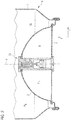
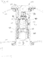
- FIG Figure 1 An embodiment of a container 1 is shown schematically in FIG Figure 1 shown.
- a filling space 40 is arranged in the upper region of the container 1.
- the filling space 40 is partially filled with a liquid and the uppermost area of the filling space 40 is filled with a gas.
- the filling space 40 is formed by a container wall 7, a container top 8 and a container base 2.
- In the lower area of the container 1 there is a pressure chamber 6, which is formed by the container base 2 and the pressure chamber base 5.
- a pressure valve 10 connects the container base 2 and the pressure chamber floor 5 and extends through the pressure chamber 6.
- In the filling chamber 40 there is a pressure p B and in the pressure chamber 6 there is a pressure p D.
- the pressure p D in the pressure chamber 6 is greater than the pressure p B in the filling chamber 40.
- the pressure p B is understood to mean the pressure that acts on the filling chamber side of the pressure valve.
- the pressure p B corresponds to the pressure in the gas-filled area of the filling space 40 plus the pressure component resulting from the liquid column up to the level at which the pressure p B acts on the pressure valve 10 on the filling space side.
- the pressure p B in the filling space 40 is greater than the ambient pressure of the container 1, so that the liquid in the filling space 40 flows out of an outlet line 30 by opening a valve 32.
- the pressure p B falls in accordance with the volume of liquid removed.
- the pressure valve 10 opens and a propellant gas flows from the pressure chamber 6 into the filling chamber 40 until a certain pressure is reached in the filling chamber 40.
- the pressure valve 10 then closes and no further gas can flow from the pressure chamber 6 into the filling chamber 40. This ensures that the pressure p B in the filling space 40 is constantly high enough to enable the liquid content of the filling space 40 to flow out by opening the valve 32 via the outlet line 30.
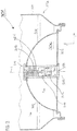
- the curvature of the container bottom 2 in the direction of the interior of the container results in an area with a small area (bottom area 1a) in the edge area of the lower area of the filling space 40, so that residual amounts of liquid in the filling space 40 can be easily reached through the outlet line 30 and only a (very) small amount of liquid cannot be removed.
- This arrangement is used to distance a possible foam formation by a liquid in the filling space 40 during or after a gas flows from the pressure space 6 into the filling space 40 from this end 30a of the outlet line 30, so that a small proportion of foam and a large proportion non-foamed liquid can be removed via the outlet line 30.
- the end of the outlet line 30 located in the filling space 40 is also below the apex of the curved container bottom 2 in the z-direction and afterwards Figure 3 also below the edge of the recess 2a in the container base 2.
- the pressure valve 10 engages in this recess of the container base 2.
- the first distance a between the end of the outlet line 30 in the filling space 40 and the pressure space floor 5 is less than the second distance b between the end 30a of the outlet line 30 in the filling space 40 and the apex of the container floor 2 (alternatively the edge of the opening of the Container bottom 2, through which the pressure valve 10 engages).
- the container bottom 2 is at least partially arched or completely dome-shaped and protrudes into the interior of the container in the positive z-direction.
- the apex and the edge of the opening of the container bottom 2 protrude in the direction of the interior 40 of the container 1.
- a filling chamber inlet 45 is arranged on the container top 8, via which the filling chamber 40 can be filled with a liquid and, if necessary, a first positive pressure can be applied.
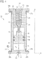
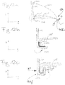
- Figure 2 shows a sectional view through the bottom area 1a of a container 1 with a detailed representation of a pressure valve 10.
- the container bottom area 1a shows a lower area of the filling space 40, the pressure space 6 and the pressure valve 10.
- the container bottom 2 is connected to the container wall 7 via a fold.
- the pressure chamber floor 5 is connected to the container floor 2.
- the pressure valve 10 engages in recesses in the container base 2 and the pressure chamber base 5 Pressure valve 10 designed in such a way that forces directed outward from the pressure chamber 6 and acting on the container base 2 and the pressure chamber base 6 are absorbed by the pressure valve 10, at least partially.
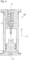
- FIG. 11 shows a container bottom area 1a in section in the z-direction similar to the embodiment in Figure 2 , but without the pressure valve 10.
- the container base 2 has a recess 2a and the pressure chamber base 5 has a recess 5a.
- the recesses 2a, 5a are axially (z-direction) in alignment along the axis A.
- the pressure valve 10 is designed, for example, in two parts.
- Such a two-part design of the pressure valve can be connected, for example, via a screw connection to form a one-part pressure valve 10, one part of the pressure valve 10 having an external thread and another part of the pressure valve 10 having an internal thread that fits the external thread.
- the pressure valve 10 can be introduced into the pressure chamber 6, for example, by inserting a part of the pressure valve into one of the two recesses 2a, 5a, inserting the second part of the pressure valve 10 into the remaining one of the two recesses 2a, 5a and screwing the two pressure valve parts together.
- the recesses 2 a, 5 a are closed in a sealed manner and the pressure valve 10 is connected to the container base 2 and the pressure chamber base 5.
- FIG. 4 shows an embodiment of a pressure valve 10 in section in the z-direction, which can be used on the bottom side in a container 1, as described above.
- the pressure valve 10 comprises a first pressure valve chamber 15 in which a pressure p V prevails.
- the first pressure valve chamber 15 is delimited by a pressure valve body 11 and a first piston 12.
- a pressure valve inlet 24 is arranged in the pressure valve body 11, via which the first pressure valve chamber 15 can be filled with a gas.
- the pressure valve inlet 24 can be closed in a fluid-tight manner by a cover 25.
- the pressure valve comprises a second pressure valve chamber 16, which is delimited by the pressure valve body 11, the first piston 12 and a second piston 13.
- the second pressure valve chamber 16 is connected via a filling chamber channel 22 to a room outside of the pressure valve 10 in a fluid-communicating manner .
- the pressure valve 10 also includes a third pressure valve chamber 17, which is delimited by the second piston 13 and the pressure valve body 11.
- the third pressure valve chamber 17 is fluidly connected to a space outside the pressure valve 10 via a first pressure chamber channel.
- a clamping element 19 is clamped between the pressure valve body 11 and the second piston 13.
- the tensioning element 19 is a spring.
- a conical section of the second piston 13 is held by the clamping element 19 in a counter-structure formed in the pressure valve body 11, so that the conical section of the second piston 13 acts as a conical seat valve.
- the pressure valve 10 is closed.
- the space that lies outside the filling chamber channel 22 is separated in a fluid-tight manner from the space that lies outside the first pressure chamber channel 20.
- a projection 28a, 28b is arranged at the lower and upper end of the pressure valve 10.
- the projections 28a, 28b protrude radially (r direction) beyond the radial extent of the pressure valve body 10. These projections 28a, 28b improve the seating of the pressure valve 10 when the pressure valve 10 is inserted into the recesses 2a, 5a of the container base 2 and the pressure chamber base 5 (cf. Figure 2 and 3 ) are introduced.
- Sealing elements 27a, 27b are arranged on the sides of the projections 28a, 28b pointing towards the pressure valve center point and on a respective axial section of the pressure valve body 11.
- seals 14a, 14b are arranged on the first piston 12.
- the seals 14a, 14b are designed as O-rings, and the seals 14a, 14b can also be implemented as molded seals.
- the seals 14a, 14b separate the first pressure valve chamber 15 and the second pressure valve chamber 16 from one another in an improved fluid-tight manner and cause a large part of the frictional force when the first piston 12 moves.
- a force which results from the pressure p V in the first, acts on the first piston 12 in the positive z direction Pressure valve chamber 15 in connection with the surface of the first piston 12 to which the pressure p V is applied.
- a force acts in the positive z-direction, which results from the pressure in the space outside the filling chamber channel 22, which rests axially on the conical section of the second piston 13.
- a force acts on the first piston 12, which results from the pressure outside of the filling chamber channel 22, which rests on the front side of the first piston 12.
- a force acts in the negative z-direction, which is exerted by the clamping element 19 on the second piston 13 and the gravitational forces of the first and second piston 12, 13.
- a force also acts from the pressure outside the first pressure chamber channel 20 results if the pressure is applied to the upper end face of second piston 13.
- the pressure outside the filling chamber channel 22 corresponds to the pressure p B of the filling chamber 40 and the pressure outside the first pressure chamber channel 20 to the pressure p D of the pressure chamber 6. If the pressure p B in the filling chamber 40 falls due to the removal of a volume of liquid , the balance of forces (as shown above) can be changed. If the pressure decrease is sufficiently large, the first and the second piston (coupling) move in the positive z-direction and the pressure valve 10 is opened.
- the threshold values S 1 and S 2 result from the geometric configuration of the pressure valve 10, specifically from the surfaces on which the illustrated pressures act, and from the level of the pressures and the clamping force of the clamping element 19.
- the pressure valve 10 When the pressure outside the filling chamber channel 22 falls below the first threshold value S 1, the pressure valve 10 opens by a movement of the first and second piston 12, 13 in the positive z direction. When the second threshold value S 2 of the pressure outside the first pressure chamber channel 20 is exceeded, the pressure valve 10 closes by moving the first and second pistons 12, 13 in the negative z-direction. If the pressure valve 10 is arranged in a container 1, the pressure outside of the Filling chamber channel 22 correspond to the pressure p B in the filling chamber 40 and the pressure outside the first pressure chamber channel 20 can correspond to the pressure p D in the pressure chamber 6.
- FIG 4 an insert 23 which can be inserted into the pressure valve body 11 is also shown.
- the clamping element 23 and the second piston 13 can be inserted into the interior of the pressure valve 10 during the manufacture of a pressure valve 10.
- the insert 23 becomes part of the pressure valve body 11.
- the pressure valve body 11 can be divided into two parts (not in Figure 4 shown), specifically so that one of the two projections 28a, 28b is arranged on one part of the two-part pressure valve body 11 and the other of the two projections 28a, 28b is arranged on the other part of the two-part pressure valve body 11.
- the two parts of the pressure valve body 11 can for example be connected by a screw connection. When the two parts are connected, a two-part pressure valve body 11 results.
- Figure 5 shows a pressure valve 10a which can be used on the bottom side in a container 1.
- the difference to the pressure valve 10 from Figure 4 is that no gas has been introduced into the pressure valve 10a through the pressure valve inlet 24, so that the first piston 12 is not coupled to the second piston 13.
- a hollow container bottom 200 is shown.
- a pressure space 206 is formed in the container hollow bottom 200.
- a pressure p D3 prevails in the pressure chamber 206.
- the pressure chamber 206 is sealed off from the environment in a fluid-tight manner by a first base 202, a second base 205 and a pressure valve 210 when the pressure valve 210 is closed. If the pressure valve 210 is open, the pressure valve 210 connects the pressure space 206 to a space surrounding the container hollow bottom 200 in a fluid-communicating manner.
- An overpressure can prevail in the pressure space 206, which means that the pressure p D3 in the pressure space 206 is greater than the pressure of the space surrounding the container hollow bottom 200 or greater than the space that forms the upper section (in the positive z-direction) of the pressure valve surrounds.
- a gas flows out of the pressure chamber 206 into the surroundings of the container hollow bottom 200 when the pressure valve 210 is open.
- the pressure valve 210 is arranged in a recess of the first base 202 and the second base 205. Such an arrangement of the pressure valve 210 closes the pressure valve 210 the recesses of the first base 202 and the second base 205. In this embodiment, the recesses of the first base 202 and the second base 205 are aligned in the z direction.
- the pressure valve 210 has a (completely) circumferential projection 228a on the upper section.
- the projection 228a is arranged in such a way that the outer surface of the first base 202 rests in sections against the projection 228a.
- a further projection 228b is arranged on the lower section of the pressure valve 210, specifically in such a way that the outer surface of the second base 205 rests against the lower projection 228b.
- the material thickness of the first base 202 and / or the second base 205 can be designed to be less than a material thickness of the bases 202, 205 without the same pressure difference between the pressure chamber 206 and the room or rooms outside the floors 202, 205 and with the same stability Force absorption of the pressure valve 210.
- the projections 228a, 228b can each be designed with circumferential interruptions.
- the pressure valve 210 can also be arranged on the inner surfaces of the bases 202, 205 (lying in the pressure space 206), for example by gluing or welding, whereby a force can be absorbed by the pressure valve 210.
- the second (lower) floor 205 is essentially flat (less than 10% deviation from the flat surface) and is arranged in a fluid-tight manner in a circumferential bead 204 of the first floor 202.
- the second base 205 can likewise be connected to the first base 202 by a flanging, welding or adhesive bond. In other embodiments, the lower floor 205 may not be planar.
- the first (upper) floor 202 is arched (in sections). In the negative r direction, starting from the circumferential bead 204, the first base 202 is formed in the form of a spherical shell segment or a hollow spherical segment with a central recess.
- the edge area 203 of the first base 202 is a connection point or connection point for a cylindrical or tubular container which is not in Figure 6 is shown, arranged.
- the edge area 203 of the first base 202 is designed such that the container hollow base 200 can be connected to a container via the edge area 203 of the first base 202 by a flange.
- Figure 6 also shows an embodiment of a container hollow bottom which can be designed by a modular system.
- a modular system comprises a first base 202, a second base 205 and a pressure valve 210 as individual components.
- the individual components of the modular system can be used to create a hollow bottom container.
- the modular design enables improved shipping compared to already assembled hollow container bottoms.
- Figures 7 , 8th and 9 show different stages during the filling of a container.
- the container 301 after Figure 7 is equal to container 1 in Figure 1 with the difference that the filling space 340 (filling space 40 in Figure 1 ) is not filled with a liquid.
- the container 301 comprises a filling space 340, which is formed between a container bottom 302, a container wall 307 and a container top side 308.
- the container top side 308 comprises a filling space inlet 345 and the passage of an outlet line 330.
- the outlet line 330 comprises a valve 332 and leads in Inside the filling space 340 up to the container bottom area 301a (at the end 30a of the inner section of the outlet line). A pressure p B4 prevails in the filling space 340.
- the container 301 further comprises a pressure chamber 306 which is formed between the container base 302 and a pressure chamber base 305.
- the container base 302 and the pressure chamber base 305 each have a recess on which a pressure valve 310 is arranged.
- a pressure p D4 prevails in the pressure chamber 306, the pressure p D4 being above atmospheric pressure (outside the container 301).
- Such a container 301 can be delivered to a bottler of a liquid, for example beer, and filled at the bottler.
- the filler fills a liquid into the filling space 340 via the filling space inlet 345.
- the filling space inlet 345 is closed.
- Figure 8 shows a detailed illustration of a container 301 filled with a liquid (in the filling space 340) for activating the pressure valve 310.
- the pressure valve 310 comprises a second pressure valve chamber 316, which is connected in a fluid-communicating manner to the filling chamber 340 via a filling chamber channel 322.
- the pressure valve 310 comprises a third pressure valve chamber 317 in which a tensioning element 319 is arranged, which exerts a force in the negative z-direction on a second piston 313.
- the third pressure valve chamber 317 is connected to the pressure chamber 306 in a fluid-communicating manner via a first pressure chamber channel 320.
- the second piston lies in the pressure valve 310 in such a way that the pressure valve 310 is in the closed state.
- the second pressure valve chamber 316 is not connected to the pressure chamber 306 via the second pressure chamber channel 321 in a fluid-communicating manner. Only the pressure p B4 in the filling chamber 340 (sum of overpressure and pressure resulting from the liquid column) exerts a force on the second piston 313 in the positive z-direction, the forces acting on the second piston 312 in the negative z-direction being greater.
- the first piston 312 rests on the pressure valve 310 at the bottom. In the negative z-direction, the weight of the first piston and a force that results from the pressure in the second pressure valve chamber 316 in connection with its surface on the first piston act on the first piston 312.
- an overpressure pressure above atmospheric pressure
- a pressure valve inlet 324 a pressure valve inlet 324.
- a cover 325 is arranged on the pressure valve 310 in the region of the pressure valve inlet 324 via webs 326. The cover 325 serves to close the pressure valve inlet 324 after the introduction of an overpressure through the pressure valve inlet 324 into the pressure valve 310.
- a force (corresponding to the level of the overpressure and the contact surface) is exerted on the first piston 312, which force is so great that the first piston 312 is guided in the positive z-direction.
- the weight of the first piston 312 the force that results from the pressure in the second pressure valve chamber, and friction forces must be overcome.
- the first piston 312 moves in the positive z-direction until it rests against the second piston 313 or, if necessary, further in the positive z-direction if the pressure introduced through the pressure valve inlet 324 is sufficiently high.
- FIG 9 a filled container 301 is shown after the introduction of the positive pressure through the pressure valve inlet 324 into the pressure valve 310 and the closure of the pressure valve inlet 324.
- a first pressure valve chamber 315 was formed by the introduction of pressure and this lies below the first piston 312.
- the first piston 312 separates the second pressure valve chamber 316 from the first pressure valve chamber 315.
- the cover 325 closes the pressure valve inlet 324.
- the pressure valve inlet 324 can be closed by friction welding (material fit).
- An ultrasonic lance is preferably applied to the cover 325.
- the cover 325 is materially connected to the pressure valve 310; the webs 326 can also be connected to the pressure valve 310 or the connection area between the cover 326 and the pressure valve 310 (materially) and do not have to be removed separately.
- first piston 312 rests against the second piston 313, they are mechanically coupled. In addition to the forces described, the force of the first piston 312 acting in the positive z direction (as a result of forces acting in the negative and positive z direction) also acts on the second piston 313. If the force acting in the negative z direction is reduced the first piston 312 by reducing the pressure p B4 in the filling chamber 340, the first piston 312 and the second piston 313 can move in the positive z-direction, so that the filling chamber 340 is fluidly connected to the pressure chamber 306 via the second pressure chamber channel 321.
- the pressure valve 310 is in the open state and a propellant gas can flow from the pressure chamber 306 into the filling chamber 340. This continues until the force influences on the first piston 312 and the second piston 313 change to the effect that the first piston 312 and the second piston 313 move in the negative z-direction until the connection between the filling chamber 340 and the pressure chamber 306 is interrupted is. Then the pressure valve 310 is closed.
- the bottler can determine the type of gas introduced, for example air, carbon dioxide, nitrogen, nitrous oxide or mixtures of gases, and can determine the pressure in the first pressure valve chamber 315 determine yourself.
- the gas introduced into the pressure valve 310 (first pressure valve chamber 315) via the pressure valve inlet 324 corresponds to the composition of the gas introduced into the pressure chamber 306 or, with regard to the composition of the component or components, deviations of no more than 20%, preferably not more than 10%, exist.
- FIG 10 illustrates a pressure valve 410 (as a control valve for the pressure in the filling space 40), used in a container.
- the valve 410 comprises a valve sleeve 444, a first valve insert 450, a second valve insert 460 and a third valve insert 470.
- the valve sleeve 444 is made of metal and is connected to a container base 402 and a pressure chamber base 405.
- the metallic sleeve can also be assigned to the container bottom, in which case it would be a ground sleeve whose jacket does not have to be completely solid, but can also follow the outline of a sleeve as a supporting frame or in a circumferentially distributed rod shape or grid shape.
- the sleeve (valve sleeve or base sleeve, depending on the viewing direction) is provided and designed to accommodate a valve member by being pushed in axially and to mechanically hold the two bases at a given (fixed) distance.
- connection of the sleeve to the base is established in that the sleeve 444 reaches through an opening in the container base 402 and a radial projection 442 a of the sleeve 444 rests on the upper side of the container base 402.
- the connection of the sleeve 444 to the pressure chamber floor 405 is shown in FIG Figure 10 shown by a reshaped projection 442b of the sleeve 444 resting against an underside of the pressure chamber floor 405. Both systems are sealing for gas under gas pressure and liquids of the type to be accommodated in the container.
- Sealing elements 443a, 443b are arranged between the projections 442a, 442b of the pressure valve sleeve 444 and the container base 402 and the pressure chamber base 405.
- Analogous to the representations of the Fig. 1 is the pressure valve 410 from Figure 10 mostly in the pressure space 406 (corresponds to space 6 of Figure 1 ), which is formed by the pressure chamber floor 405 and the container floor 402 (corresponds to floor 5 and floor 6 of Figure 1 ).
- the pressure space 406 can have the properties disclosed above.
- the pressure p D5 in the pressure space 406 is above the ambient pressure, especially in the case of pressure values, as already described above for pressure spaces.
- a control valve is pushed into the sleeve 444, which functionally fulfills the task of pressure regulation, detached from the task of mechanical stabilization.
- the control valve can, by its nature, be made of plastic, even if one or the other spring or metallic membrane is built into it.
- a first pressure valve insert 450 is pushed into the sleeve 444.
- the first pressure valve insert 450 is arranged in a force-locking manner in the pressure valve sleeve 444.
- the non-positive connection is given by an oversize of the first pressure valve insert 450 compared to the dimension of the pressure valve sleeve 444.
- the outer diameter of the sleeve 444 can be less than 30 mm.
- the inner diameter of the sleeve 444 is reduced by twice its wall thickness.
- the outside diameter of the first pressure valve insert 450 can be up to 0.5 mm, preferably between 0.1 mm and 0.3 mm larger than the inside diameter of the pressure valve sleeve 444.
- sealing elements 451a, 451b, 451c bring about the force-fit connection with the pressure valve sleeve 444.
- the sealing elements can be designed in the shape of an O-ring.
- the first pressure valve insert 450 comprises a first channel 422 (as a filling chamber channel) which connects a (second) space 416 located in the pressure valve 420 with a filling chamber 440 of the container. In the filling space 440 there is a pressure p B5 which is less than the pressure p D5 in the pressure space 406.
- the first pressure valve insert 450 comprises a second channel 420 (as a pressure chamber channel) which opens into a circumferential groove 454 (as an annular channel) in the first pressure valve insert 450.
- An opening 441, which opens into the pressure chamber 406, is arranged in the sleeve. Extensive adjustment of the pressure valve insert 450 when it is pressed into the sleeve is thus avoided.
- the first pressure valve insert 450 has a radially cantilevered projection 452 which engages over the radial projection 442a of the sleeve 444 and rests in the end area on the upper side of the container bottom 402.
- the first pressure valve body can preferably be made of plastic.
- a liquid in the filling space 440 does not come into direct contact with the metallic sleeve 444 in order to avoid a corrosive effect. In addition, it improves the resilience of the pressure valve 410.
- a second pressure valve insert 460 which is explained below, is connected to the first pressure valve insert 450.
- a third pressure valve insert 470 is arranged between the second space 416 and the second channel 420.
- the third pressure valve insert 470 is connected to the first pressure valve insert 450 in a force-fitting or form-fitting manner.
- the third pressure valve insert 470 comprises an opening 477 which connects a (third) space 417 located in the third pressure valve insert 470 to the pressure space 406 via the second channel 416, so that the pressure in the third space 417 (almost) corresponds to the pressure p D5 in the pressure space 406 .
- a tensioning element 473 is fastened in the third space 417 via a tensioning element guide 474.
- the tensioning element 473 is also connected to a sealing plate 475 of a plate valve 475, 476 and presses the sealing plate 475 into a valve seat 476.
- the second insert 460 is connected to the first insert 450.
- the connection can be provided in a force-fitting or form-fitting manner, a screw connection or a weld, especially by friction welding, being preferred.
- the second pressure valve insert 460 comprises a membrane 461, which preferably consists of a flexible plastic.
- a contact element 462 is formed on the membrane 461 as a thickened section of the membrane 461.
- a further tensioning element 463 is arranged on the membrane 461 of the second pressure valve insert 460.
- the tensioning element 463 is arranged in a (first) space 415 located in the second pressure valve insert 460 and exerts a force between the membrane 461 and a closing element 480.
- the locking element 480 is in Figure 10 loosely or only weakly connected to the second pressure valve insert 460.
- the function of the closing element 480 can best be described by considering the different states from the Figures 10 and 11 describe.
- the closing element 480 is not permanently connected to the tensioning element 462. It comprises a radial projection 481 and an axial channel 482. The closing element 480 is designed so that it can be pushed into the second pressure valve insert 460 from the outside.
- the second pressure valve insert 460 comprises a groove 464 and an annular stop surface 465.
- the groove 464 is configured to correspond to the projection 481 of the closing element 480.
- the distance between the contact surface 465 and the groove 464 is not smaller than the distance between the projection 481 and the upper side (in the positive z-direction) of the closing element 480.
- the closing element 480 can be introduced into a (fourth) space 418 in the pressure valve sleeve 444, for example with the aid of a stamp-like closing device 490, and further into positive z-direction into the second pressure valve insert 460 until the radial projection 481 of the closure element 480 engages in the circumferential groove 464 of the second pressure valve insert 460 and possibly the top (in the positive z-direction) of the closure element 480 on the contact surface 465 of the second Pressure valve insert 460 rests (hits).
- the tensioning element 463 is tensioned, as a result of which a force is exerted on the membrane 461 and the membrane 461 moves in the positive z-direction until it is in contact with a section of the sealing plate 475, for example through the contact element 462.
- the pressure valve 410 is activated and there is an equilibrium of forces between the pressure p B5 in the filling chamber 440, the pressure p D5 in the pressure chamber 406 and the clamping elements 463, 473.
- the pressure p D5 in the pressure chamber acts on the contact surface of the sealing plate 475 in the negative z-direction.
- a force applied by the tensioning element 473 to the sealing plate 475 acts in the negative z-direction on the sealing plate 475.
- the pressure p B5 in the filling chamber acts on the contact surface of the membrane 461 in the negative z-direction, with the membrane 461 is coupled to the sealing plate 475.
- a small, actually negligible force also results from the pressure p B5 in the filling space 440 in the positive z-direction, acting on the sealing plate 475, and low due to the small or negligible application area of the pressure p B5 on the sealing plate 475.
- the tensioning element 463 exerts a force in the positive z-direction on the membrane 461, which force is passed on to the sealing plate 475 because of the coupling between the membrane 461 and the sealing plate 475.
- the force influences in the positive z-direction predominate, so that the sealing plate 475 is lifted out of the valve seat 476 and the pressure chamber 406 is connected to the filling chamber 440 in a fluid-communicating manner until a further threshold value of the pressure p B5 is exceeded in the filling chamber 440 and the sealing plate 475 moves back into the valve seat 476.
- a further threshold value of the pressure p B5 is exceeded in the filling chamber 440 and the sealing plate 475 moves back into the valve seat 476.
- Figures 12a, 12b, 12c illustrate a possibility for connecting a mechanically stable sleeve 444 to a container base 402 and a pressure chamber base 405.
- the metallic pressure chamber floor 405 is welded to the metallic container floor 405 at 405s, which is shown by the two arrows S and S ′ facing one another.
- the sleeve 444 can be guided or inserted through an opening in the container base 402 and through an opening in the pressure chamber base 405, so that a projection 442a of the pressure valve sleeve 444 rests on the top of the container base.
- the opposite end of the sleeve 444 protrudes from the opening in the pressure chamber floor 406 and rests against an axial projection 405b of the pressure chamber floor 405 in a radially directed manner.
- the sealing connection of the sleeve 444 to the pressure chamber floor 405 can be produced via a fold 444f, in particular as a double fold, which is shown in the enlarged illustrations of the relevant section of FIG Figures 12b and 12c is recognizable. The forces F and F 'to form the fold are shown.
- a sealing element 443b is arranged between the sleeve 444 and the pressure chamber floor 405.
- a (slight) pre-tension is applied to the pressure chamber floor 405 by pressing the pressure chamber floor 405 in the direction of the container floor 402.
- This is in Figure 12a shown by a changed (exaggerated large drawn) position of the pressure chamber floor 405 and the projection 405b relative to the container floor 402 as the pressure chamber floor 405 'and its projection 405b'.
- a preload can improve the tightness of the connection.
- the fold formation 444f takes place in one example as follows.
- a section of the pressure valve sleeve 444 protruding in the negative z-direction over the projection 405b 'of the pressure chamber floor 405' is bent in the positive r-direction over the projection 405b 'over the entire circumference, so that a projection 442b of the pressure valve sleeve 444 is formed.
- the bent over projection 442b is further bent or folded around the projection 405b '(over the entire circumference) so that the end of the projection 443b is aligned in the positive z-direction.
- the section of the sleeve 444 which is bent around the projection 405b 'of the pressure chamber floor 405' is then pressed by exerting a force in the positive and / or negative r-direction.
- All pressure valves disclosed can each be used in disclosed containers, hollow container bottoms or modular systems for producing a hollow container bottom, even if these are encompassed by methods.
- the disclosed filling spaces and pressure spaces can be used in all disclosed containers, container hollow bottoms or modular systems for producing a container bottom, even if these are covered by methods.
Landscapes
- Chemical & Material Sciences (AREA)
- Dispersion Chemistry (AREA)
- Engineering & Computer Science (AREA)
- Mechanical Engineering (AREA)
- Filling Or Discharging Of Gas Storage Vessels (AREA)
- Containers And Packaging Bodies Having A Special Means To Remove Contents (AREA)
- Filling Of Jars Or Cans And Processes For Cleaning And Sealing Jars (AREA)
- Packages (AREA)
- Devices For Dispensing Beverages (AREA)
Description
- Die Erfindungen betreffen das technische Gebiet der Verpackungstechnik. Speziell betrifft eine Erfindung einen Behälter, dessen Inhalt durch einen Verbraucher komfortabel entnehmbar ist, insbesondere unter einem erhöhten Innendruck im Vergleich zum Außendruck steht. Speziell betrifft eine weitere Erfindung ein Druckventil für den genannten Behälter. Speziell betrifft eine noch weitere Erfindung ein Regelverfahren für den Druck in einem Behälter. Zusätzlich betrifft eine weitere Erfindung einen Behälterhohlboden und ein modulares System zur Herstellung eines Behälterhohlbodens. Weiterhin betrifft eine weitere Erfindung ein Verfahren zum Befüllen eines Behälters.
- Der Behälter ist vergleichsweise voluminös, deutlich größer als eine gängige Getränkedose und der Inhalt ist ein Getränk, das unter Druck gezapft werden soll.
- Tragbare Bierfässer, solche mit einem Volumen unter 50 Liter, insbesondere unter 20 Liter und mehr als 2,5 Liter, deren Inhalt von Verbrauchern eigenständig gezapft werden können sind in zwei gebräuchlichen Varianten von besonderer Bedeutung.
- Eine Variante solcher, mit metallischem Mantel versehenen, tragbaren Bierfässer lässt sich durch die Wirkung der Gravitationskraft entleeren. Ein Zapfhahn ist dabei im unteren Bereich der Außenseite des Behälters angeordnet. Durch Öffnen des Hahns kann das Bier ausfließen. Damit im Behälter kein Unterdruck entsteht, umfassen solche Behälter eine Vorrichtung, die es erlaubt, dass Luft aus der Umgebung in das Innere des Behälters gelangt. Solche Behälter sind wenig bedienerfreundlich, da zum Befüllen eines Glases mit Bier das Fass beispielsweise an den Rand eines Tisches gestellt werden muss oder das Fass unterbaut werden muss, um das Glas unterhalb des Zapfhahns befüllen zu können. Zusätzlich wird die Haltbarkeit des Fassinhalts nach Anbruch des Fasses durch beim Ausfließen des Bieres einströmenden Luftsauerstoff erheblich reduziert.
- Eine andere Variante sind Behälter, die ein Innendrucksystem umfassen. Durch diese Systeme wird der Druck im Inneren über dem Umgebungsdruck gehalten. Dies erlaubt die Anordnung des Zapfhahns im oberen Bereich des Behälters. Ein Verbraucher hat dadurch typischerweise ausreichend Raum zwischen dem unteren Auslaufende des Zapfhahns und der Standebene des Behälters, um ein zu befüllendes Glas unter den Zapfhahn zu halten, ohne das Fass speziell positionieren zu müssen. Durch die Verwendung von Innendrucksystemen kann die Haltbarkeit des Bieres nach Anbruch des Fasses bis zu mehr als 30 Tage betragen, da während der Bierentnahme kein Luftsauerstoff in das Fass einströmt.
- Ein Bierfasssystem der zweiten Variante ist dem Fachmann aus
WO 1999/47451 - Dieses System hat sich im Markt seit vielen Jahren als die best-funktionierende Lösung für tragbare Bierfässer mit einem Inhalt unter 20 Liter erwiesen. Sie wurde sozusagen zum Marktstandard. Hinsichtlich der möglichen Vielseitigkeit beim eingefüllten Treibgas besteht indes eine eingeschränkte Flexibilität, da solche Kartuschen vom Abfüller bereits mit Treibgas befüllt erworben werden und in die Bierfässer (als metallische Behälter) eingebaut werden, um noch später vom Abfüller mit dem Bier gefüllt zu werden.
- Dazuhin ist der Werkstoff des "Carbonators" aus einem anderen Metall als der Werkstoff der Wand des Bierfasses. Dies führt im Recyclingprozess zu einem Mischschrott (u.a. Material der Wandung des "Carbonators" und Material der Außenwandung des Bierfasses), was zur Vermeidung zukünftig mehr und mehr Beachtung erhält.
-
US 2,345,081 (Ward ) aus 1944 betrifft einen Syphon (ein Dispenser für Mineralwasser). Dieser hat eine Bodenkonstruktion mit einem Druckraum zum Zwischenspeichern eines Gases unter deutlich über Atmosphärendruck liegendem Druck, das über eine Ventilkonstruktion VB in eine mit Flüssigkeit (Mineralwasser, aber nicht Bier) gefüllte Kammer (einen Befüllraum LC) gesteuert abgelassen werden kann. Der Druckraum hat auf beiden axialen Enden eine jeweils nach innen (in den Druckraum hinein) ausgewölbte Wand. Zum Bereitstellen des primären Drucks in diesem Druckraum wird eine Hochdruck-Kartusche GB an das untere Ende des Syphon (als Behälters) gesteckt (mit einer Muffe angeschraubt), wodurch der Syphon nicht mehr auf einem flachen Boden (oder ebenen Tisch) zu stehen vermag. - Ein Behälter nach dem Oberbegriff des Anspruchs 1 ist aus der
DE 20 2005 017 072 U1 bekannt. - Die Erfindung betrifft einen Behälter nach Anspruch 1 und ein Verfahren nach Anspruch 13. Ausfürungsbeispiele ermöglichen es, ein System bereitzustellen, das bei hohem Bedienungskomfort durch einen Verbraucher preiswert herstellbar ist, eine hohe Flexibilität hinsichtlich der Treibgaswahl (Druck und Art des Gases) zur Verfügung stellt und eine lange Haltbarkeit des Inhalts erzielt, auch nach Anbruch des Behälters.
- Ein beanspruchter Behälter zum Aufbewahren einer Flüssigkeit umfasst einen Befüllraum (auch: Füllraum), einen Druckraum und ein Druckventil. Der Befüllraum ist gebildet durch einen Behälterboden, eine Behälterwand und eine Behälteroberseite und in dem Befüllraum herrscht ein erster Druck. Der Druckraum ist gebildet durch den Behälterboden und einen Druckraumboden und in dem Druckraum herrscht ein zweiter Druck. Das Druckventil ist mit dem Behälterboden und dem Druckraumboden verbunden. In geöffnetem Zustand des Druckventils verbindet das Druckventil den Befüllraum und den Druckraum fluidkommunizierend. In geschlossenem Zustand des Druckventils trennt das Druckventil den Befüllraum und den Druckraum fluiddicht gegeneinander ab.
- Wenn der zweite Druck im Druckraum größer ist als der Umgebungsdruck und/oder der Druck im Befüllraum, wirken Kräfte auf den Behälterboden und auf den Druckraumboden, die jeweils vom Inneren des Druckraumbodens nach außen gerichtet sind. In Abhängigkeit der Druckdifferenz und der Materialstärke des Druckraumbodens und des Behälterbodens kann es zu einer Verformung oder Ausbeulung des Behälterbodens und/oder des Druckraumbodens kommen. Durch das Verbinden des Druckventils mit dem Behälterboden und mit dem Druckraumboden, kann ein Teil der Kräfte durch das Druckventil aufgenommen werden.
- Dies erlaubt bei konstanter Druckdifferenz die Wahl einer geringeren Materialstärke des Behälterbodens und/oder des Druckraumbodens als eine Materialstärke, die unter Vermeidung einer Verformung oder Ausbeulung des Behälterbodens und/oder des Druckraumbodens notwendig wäre. Bei konstanter Materialstärke erlaubt die Anordnung des Druckventils einen höheren Differenzdruck (beispielsweise hoher Druck im Druckraum) bei gleichzeitiger Vermeidung der erwähnten Verformung oder Ausbeulung.
- Fluidkommunizierend bedeutet, dass ein Fluidaustausch zwischen zwei Räumen (beispielsweise Befüllraum und Druckraum) möglich ist, insbesondere zügig und nicht zäh. Fluiddicht bedeutet, dass zwischen zwei Räumen praktisch kein Fluidaustausch stattfinden kann; dabei versteht der Fachmann, dass eine perfekte Abdichtung zweier Räume ohne jedweden Fluidaustausch oder Fluidfluss stattfindet praktisch nicht realisierbar ist. Parasitärer Fluss oder Austausch ist immer gegeben, so dass es kein praktisch erheblicher Austausch ist. Ein marginaler Fluidfluss oder Fluidaustausch wird auch zwischen zwei fluiddicht gegeneinander abgetrennten Räumen stattfinden, wobei die Druckdifferenz zwischen den beiden Räumen einen Einfluss auf die Menge des parasitär ausgetauschten Fluids pro Zeiteinheit hat. Jedenfalls ist der Fluidaustausch in geschlossenem Zustand des Druckventils, also fluiddicht, sehr viel geringer als der Fluidaustausch bei geöffnetem Zustand des Druckventils, also fluidkommunizierend. Der Behälterboden und der Druckraumboden können je eine Ausnehmung aufweisen. In diese Ausnehmungen kann das Druckventil eingreifen, wodurch eine Kraft, die aus einer Druckdifferenz zwischen dem Druckraum und dem Befüllraum und dem Druckraum und der Umgebung resultiert, aufgenommen werden kann.
- Das Druckventil kann einen Druckventilkörper aufweisen. Am oberen und am unteren Ende des Druckventils kann jeweils ein Vorsprung angeordnet sein, wobei der obere und der untere Vorsprung jeweils zumindest teilumfänglich in r-Richtung über zumindest einen radialen Teil des Druckventilkörpers ragen. Dabei können die Vorsprünge (oben und unten) über den kompletten Umfang des Druckventils ausgebildet sein oder teilumfänglich ausgebildet sein. Auch eine Ausbildung mehrerer Vorsprünge pro axialem Ende des Druckventils (oben und unten) ist möglich, wobei jeder der Vorsprünge teilumfänglich ausgebildet sein kann. Bevorzugt kontaktiert der Vorsprung am oberen Ende des Druckventils die obere Seite des Behälterbodens und der Vorsprung am unteren Ende des Druckventils die untere Seite des Druckraumbodens. Dadurch kann wiederum die auf den Behälterboden und den Druckraumboden wirkende Kraft, die aus der beschriebenen Druckdifferenz resultierend, zumindest teilweise vom Druckventil aufgenommen werden.
- Die Vorsprünge des Druckventils können ein Dichtelement umfassen. Je nach Ausbildung der Vorsprünge (oben und unten am Druckventil), können mehrere Dichtelemente pro Seite des Druckventils angeordnet sein oder lediglich ein Dichtelement oder Dichtelemente an einem Vorsprung oder an Vorsprüngen einer Seite des Druckventils angeordnet sein. Durch das Anbringen eines Dichtelements ist eine verbesserte Dichtheit an der Kontaktstelle zwischen Druckventil und Behälterboden und/oder Druckraumboden erreichbar.
- Der Behälter kann eine Auslassleitung mit einem Ende und einem anderen Ende umfassen. Das eine Ende der Auslassleitung kann in dem Befüllraum liegen Typischerweise kann ein Verbraucher über die Auslassleitung einen Inhalt aus dem Befüllraum entnehmen (zapfen). Der Behälterboden kann in seinem Innenbereich gewölbt oder ganz kuppelförmig ausgestaltet sein, in Richtung zum Befüllraum. Zumindest ein Abschnitt des Behälterbodens ist also gewölbt ausgestaltet. Zwischen dem unteren Ende eines Abschnitts der Auslassleitung, das in dem Befüllraum liegt, und einem Punkt auf dem Druckraumboden (der Oberfläche des Druckraumbodens) besteht ein (erster) Abstand. Bevorzugt handelt es sich bei dem Abstand um den kürzesten Abstand eines Punktes auf dem Druckraumboden und dem im Befüllraum liegenden Ende. Der kürzeste Abstand kann durch die Wahl eines Punktes auf dem Druckraumboden bestimmt werden, der den geringsten Abstand zu dem im Befüllraum liegenden Ende der Auslassleitung aufweist. Der Abstand zwischen dem beschriebenen Ende des innen liegenden Abschnitts der Auslassleitung und dem Druckraumboden kann geringer (kleiner) sein als ein Abstand zwischen dem beschriebenen Ende der Auslassleitung und dem Scheitelpunkt des gewölbten Bodenabschnitts. Befindet sich dort bereits eine Ausnehmung (für das Druckventil) ist es der Rand der Ausnehmung des Behälterbodens, wobei auch hier ein Scheitelpunkt extrapolierbar ist (in der Mitte der Ausnehmung).
- Auch wenn der Behälterboden zumindest partiell gewölbt oder ganz kuppelförmig ausgestaltet ist und eine mittige Öffnung aufweist, und zwar an einer Stelle des Behälterbodens, an welcher der Scheitelpunkt auf dem Behälterboden liegen würde, wenn der Behälterboden die Öffnung nicht aufweisen würde oder die Öffnung an einer anderen Stelle liegen würde, weist der Behälterboden einen Scheitelpunkt auf. Der Scheitelpunkt ist in diesem Fall durch eine Extrapolation zu bestimmen und ist an einer Stelle gelegen, an der der Scheitelpunkt auf dem Behälterboden liegen würde, wenn keine Öffnung in dem Behälterboden vorhanden ist oder die Öffnung an einer anderen Stelle vorhanden ist.
- Durch die Anordnung des Endes der Auslassleitung nahe am Druckraumboden ergibt sich eine vorteilhafte Entnahmemöglichkeit des (fast ganzen) Inhalts des Behälters über die Auslassleitung, speziell wenn der Inhalt eine zum Schäumen neigende Flüssigkeit ist, z.B. Bier, und der Füllstand im Befüllraum niedrig ist.
- Anders ausgedrückt, befindet sich der tiefste Punkt (oder die tiefste umlaufende Rinne) des Befüllraums unter dem höchsten Punkt des Behälterbodens. Erstere liegt radial aussen, Zweitere liegt im Zentrum. In die Rinne ragt das Ende der Auslassleitung. Wenn Gas aus dem Druckraum über das Druckventil in den Befüllraum strömt, kann die Flüssigkeit im Befüllraum zu einem erheblichen Anteil aufgeschäumt werden. Der Schaum breitet sich, wegen der geringen Dichte, oberhalb des Auslasses und lateral dazu aus und lagert sich primär nahe der Grenzfläche im Befüllraum an. Ein Verbraucher entnimmt dem Behälter dabei einen erheblichen Anteil an Schaum, wenn das innere Ende der Auslassleitung dem Ventil zu nahe käme.
- Überraschend hat sich gezeigt, dass die beschriebene Anordnung des im Befüllraum liegenden Endes der Auslassleitung relativ zu dem Behälterboden und dem Druckraumboden die Entnahme des Inhalts verbessert. Es wird weniger Schaum entnommen.
- Bei einem Behälter mit Auslassleitung kann auch eine z-Achse durch den Behälter gebildet sein. Die z-Achse erstreckt sich darin von oder durch den Druckraumboden in Richtung der Behälteroberseite. Entsprechend liegt für den Druckraumboden ein geringerer Zahlenwert auf der z-Achse vor als für die Behälteroberseite. Das Ende der Auslassleitung kann nicht oberhalb (also auf gleicher Höhe oder unterhalb) des Druckventils hinsichtlich der z-Achse angeordnet sein.
- Diese Anordnung bringt den oben beschriebenen Vorteil der Entnahme eines geringeren Anteils von unerwünschtem Schaum mit sich.
- In einem Behälter mit Auslassleitung und einer z-Achse, wie oben beschrieben, kann der Behälterboden gewölbt oder kuppelförmig ausgestaltet sein. Dabei ist zumindest ein Abschnitt des Behälterbodens gewölbt oder kuppelförmig ausgestaltet. Ein Ende der Auslassleitung, speziell ein Ende, das in dem Befüllraum liegt, kann nicht oberhalb (gleiche Höhe oder unterhalb) des Scheitelpunkts oder des Rands einer Öffnung des Behälterbodens liegen.
- Das oben beschriebene zur Bestimmung des Scheitelpunkts ist auch bei diesem Behälter anzuwenden. Die Ausgestaltung weist wiederum den Vorteil der verminderten Entnahme von Schaum aus dem Befüllraum auf.
- Der Druck im Druckraum kann mindestens 1 bar größer sein als im Befüllraum. Bevorzugt ist der Druck im Druckraum mindestens 2 bar, besonders bevorzugt mindestens 3 bar, größer als der Druck im Befüllraum.
- Ist der Druck im Druckraum größer als im Befüllraum findet, kann eine relativ große Stoffmenge von Treibgas (hoher Druck) in dem Druckraum bevorratet sein und gleichzeitig der Druck im Befüllraum (relativ) niedriger sein, was zu einem besseren und, über unterschiedliche Füllgrade des Befüllraums hinweg, stabileren Entnahmeverhalten führt. Jedes hierin offenbarte Druckventil kann ein Regelventil sein.
- Der Druckraum kann mit einem Treibgas befüllt sein. Das Treibgas ist bevorzugt Kohlenstoffdioxid (CO2), Stickstoff (N2), Lachgas (N2O) oder Mischungen der Gase.
- Bevorzugt liegt der Druck im Druckraum zwischen 5 bar (0,5 MPa) und 35 bar (3,5 MPa), speziell liegt der Druck zwischen 5 bar und 30 bar, spezieller zwischen 8 bar und 25 bar (Anspruch 10). Der Druck im Druckraum bestimmt sich auch über das Volumen des Druckraums, sodass bei einem größeren Volumen des Druckraums unter Vorhandensein einer konstanten Stoffmenge geringer sein kann oder bei einem größeren Volumen des Druckraums der Druck höher liegen kann.
- Der Druck im Befüllraum kann kleiner als der Druck im Druckraum sein. Speziell kann der Druck im Befüllraum zwischen 1,2 bar (0,12 MPa) und 7 bar (0,7 MPa), spezieller zwischen 1,5 bar und 6 bar, noch spezieller zwischen 1,7 und 5 bar liegen.
- Das Volumen des Druckraums kann zwischen 0,1 L und 5 L, speziell zwischen 0,1 L und 3 L, spezieller zwischen 0,5 L und 2,5 L, noch spezieller zwischen 0,5 L und 1,5 L liegen.
- Das Volumen des Befüllraums kann zwischen 1 L und 25 L speziell zwischen 2 L und 20 L liegen (Anspruch 11). Bevorzugt besitzt der Befüllraum ein Volumen, das es erlaubt, 2 L, 3 L, 5 L oder 20 L einer Flüssigkeit aufzunehmen, sodass bevorzugt neben der Flüssigkeit im Befüllraum ein gasgefüllter Bereich von mindestens 0,05 L besteht. Der Druckraum kann keinen Filler umfassen. Ein Filler ist eine Komponente, die typischerweise bei Umgebungsbedingungen in festem Aggregatzustand vorliegt und die Aufnahme einer Stoffmenge eines Stoffes erlaubt. Dabei fällt die Druckzunahme, in dem Raum, in dem der Filler eingebracht ist, durch das Einbringen des Stoffes geringer aus, verglichen mit dem Einbringen der gleichen Stoffmenge in den gleichen Raum ohne Filler.
- Der Dampfdruck des Treibgases oder der Treibgasmischung kann über dem Druck des Druckraums liegen, speziell bis zu einer Temperatur von -5 °C hinab.
- Entsprechend liegt das Treibgas oder die Treibgasmischung im Druckraum zum allergrößten Teil gasförmig vor, wobei dem Fachmann bewusst ist, dass auch in diesem Zustand ein (sehr) geringer Anteil des Treibgases oder der Treibgasmischung in flüssiger Form vorliegt (vgl. Oberflächenenergie- oder Oberflächenspannungseffekte an stark gekrümmten Oberflächen).
- Das Vorliegen des Treibgases größtenteils als Gas verbessert die Sicherheit des Behälters gegenüber einer in erheblichem Maße als Flüssigkeit vorliegenden Treibgasbefüllung. Ist das Treibgas in erheblichem Maße bei Raumtemperatur und darunter flüssig, kann ein Aufheizen des Behälters (z.B. wenn ein Verbraucher den Behälter eine längere Zeit intensiver Sonnenstrahlung und/oder hoherTemperatur aussetzt) dazu führen, dass eine Phasenumwandlung von der flüssigen in die gasförmige Phase stattfindet, wodurch sich der Druck erheblich erhöhen kann. Dies kann zum Versagen des Druckraumwandmaterials führen. Zusätzlich ist ein solcher Druckanstieg durch Phasenumwandlung problematisch, wenn ein Verbraucher den Behälter zum ersten Mal verwendet.
- Im Rahmen der Erfindung erlaubt die Anordnung des Druckventils im Behälter, falls es zu einem sehr hohen Druckanstieg im Druckraum kommen sollte, dass der Überdruck über den Druckraumboden, gegebenenfalls unter Zerstörung des Druckventils, an die Umgebung abgegeben wird. Dies ist gegenüber dem Stand der Technik vorteilhaft, da bei Behältern des Standes der Technik meist der gesamte Behälter bersten wird, wenn ein kritischer Druck überschritten wird.
- Bevorzugt ist der Behälterboden zumindest im radialen Innenbereich aufwärts gewölbt oder insgesamt kuppelförmig ausgebildet, vielleicht ausgenommen der äußere Randbereich. Speziell ist der Behälterboden in z-Richtung zum Behälterinneren (zum Befüllraum hin) gewölbt ausgebildet. Insbesondere ragt der Scheitelpunkt oder der Rand einer Ausnehmung des Behälterbodens in Richtung des Befüllvolumens für die Flüssigkeit.
- Durch eine Wölbung des Behälterbodens lässt sich ein Raum aus nur insgesamt zwei Bauteilen (hier Behälterboden und Druckraumboden) bilden. Zusätzlich ergibt sich eine verbesserte Kraftaufnahme des gewölbten Bauteils gegenüber einem nicht gewölbten Bauteil. Weiterhin erlaubt ein nach innen (zum Befüllraum) gewölbter Behälterboden eine weiter gehende Entleerung eines befüllten Behälters, da sich bei konstanter Restfüllmenge im Randbereich des Befüllraums des Behälters eine gegenüber einem ebenen oder in anderer z-Richtung gewölbtem Behälterboden eine vergrößerte Füllhöhe ergibt (bei kleinerer Querschnittsfläche), vgl. dazu
US 2,345,081 (Ward ), eingangs angesprochen und dargelegt. - Der Druckraumboden kann im Wesentlichen ebenflächig ausgestaltet sein, speziell ist der Druckraumboden im Wesentlichen parallel zur Behälteroberseite ausgebildet.
- Das "im Wesentlichen" erlaubt eine Abweichung zur Ebenflächigkeit und Parallelität um 10 %. Dies ist ausreichend zum Montieren einer metallischen Bodenhülse, die zwischen beiden Ausnehmungen der Böden verläuft und mit diesen dichtend verbunden ist. So kann die Abweichung von der Ebenflächigkeit genutzt werden, eine Spannung auf die Bodenhülse aufzubringen, wobei der Behälterboden leicht nach oben ausgelenkt ist, und die Bodenhülse oben verspannend aufgenommen wird.
- Die Bodenhülse entlastet das eigentliche funktionelle Ventil von axialen Kräften, welches funktionelle Ventil in die schon montierte Bodenhülse eingeschoben werden kann, und darin axial unverschieblich montiert wird.
- Der Druckraumboden kann so ausgestaltet sein, dass beim aufrechten Stehen des Behälters auf einem ebenflächigen Untergrund der Druckraumboden nicht den ebenflächigen Untergrund kontaktiert.
- Bevorzugt sind der Behälterboden, der Druckraumboden, die Behälterwand und/oder die Behälteroberseite aus metallischem Blech mit einer jeweiligen Wanddicke von weniger als 1,0 mm. Insbesondere beträgt die Wanddicke weniger als 0,8 mm, noch bevorzugter weniger als 0,55 mm.
- Durch eine geringe Materialstärke (Wanddicke) der Komponenten des Behälters ergibt sich eine besonders wirtschaftliche Verwendungsmöglichkeit als Einmal-Behälter. Ein Einmal-Behälter wird nach dessen Gebrauch von einem Verbraucher typischerweise entsorgt und nicht wiederverwendet.
- Jeder hierin offenbarte Behälter kann ein Fass, insbesondere ein Bierfass, sein.
- Ein Druckventil für einen Behälter kann einen Druckventilkörper, einen ersten Druckventilraum, einen zweiten Druckventilraum und einen dritten Druckventilraum umfassen. Der erste Druckventilraum ist durch den Druckventilkörper und einen ersten bewegbaren Kolben gebildet. Der zweite Druckventilraum ist durch den Druckventilkörper, den ersten bewegbaren Kolben und einen zweiten bewegbaren Kolben begrenzt. Der zweite Druckventilraum ist über einen Befüllraum-Kanal mit einem ersten, außerhalb des Druckventils liegenden Raum fluidkommunizierend verbunden. Der dritte Druckventilraum ist durch den Druckventilkörper und den zweiten Kolben begrenzt und ist über einen ersten Druckraumkanal mit einem zweiten, außerhalb des Druckventils liegenden Raum fluidkommunizierend verbunden. Der erste und zweite bewegbare Kolben wird bevorzugt in ihrer jeweiligen Bewegung geführt und speziell ist eine Bewegung im Wesentlichen nur in axialer Richtung (z-Richtung) möglich. Dabei bezieht sich das "im Wesentlichen" darauf, dass bei erfindungsgemäßem Gebrauch die axiale Bewegbarkeit die Hauptbewegbarkeit ist. Der erste, außerhalb des Druckventils liegende Raum kann jeder Raum sein, der außerhalb des Druckventils liegt, speziell ist es ein Befüllraum. Ebenso kann der zweite, außerhalb des Druckventils liegende Raum jeder Raum sein, der außerhalb des Druckventils liegt. Bevorzugt ist dieser Raum der Druckraum. Zur Fluidkommunikation wird auf die Ausführungen oben verwiesen.
- Der Druckventilkörper kann einen zweiten Druckraumkanal umfassen, der im geschlossenen Zustand des Druckventils an einem Ende des zweiten Druckraumkanals durch den ersten Kolben fluiddicht abgeschlossen ist und an einem anderen Ende gegenüber dem zweiten, außerhalb des Druckventils liegenden Raum geöffnet ist
- Bevorzugt sind der zweite Druckventilraum und der zweite, außerhalb des Druckventils liegende Raum bei geöffnetem Zustand des Druckventils durch den zweiten Druckraumkanal fluidkommunizierend verbunden. Speziell sind in geöffnetem Zustand des Druckventils der erste, außerhalb des Druckventils liegende Raum und der zweite, außerhalb des Druckventils liegende Raum fluidkommunizierend verbunden.
- Das Druckventil kann ein Sitzventil umfassen. In abdichtendem Zustand des Sitzventils ist das Druckventil geschlossen und in nicht abdichtendem Zustand des Sitzventils ist das Druckventil geöffnet.
- Bevorzugt umfasst das Sitzventil ein Dichtelement, wobei das Dichtelement durch einen Abschnitt des zweiten Kolbens gebildet und das Dichtelement fluiddichtend an einem Abschnitt des Druckventilkörpers anliegen kann. Speziell ist das Dichtelement kegelförmig, kugelförmig oder tellerförmig ausgebildet, sodass sich ein Kegelsitzventil, Kugelsitzventil oder Tellersitzventil ergibt.
- Der erste bewegbare Kolben kann mit dem zweiten bewegbaren Kolben mechanisch gekoppelt sein, sobald der Druck im ersten Druckventilraum so groß ist, dass sich der erste Kolben auf Grundlage des Drucks in z-Richtung auf den zweiten Kolben zu bewegt und diesen kontaktiert. Durch den Druck im ersten Druckventilraum wirkt eine Kraft auf den ersten Kolben in Abhängigkeit der Fläche des ersten Kolbens auf die der Druck wirkt. Durch Überwindung zumindest einer Reibungskraft und ggf. einer Gewichtskraft kann sich der erste Kolben bewegen.
- Bevorzugt umfasst der erste Kolben ein Aufnahmeelement, wodurch der erste Kolben und der zweite Kolben koppelbar sind.
- Der erste Kolben kann eine Dichtung umfassen. Bevorzugt ist die Dichtung eine angespritzte Dichtung oder ein O-Ring. Speziell kann die angespritzte Dichtung durch eine 2-Komponenten-Herstellung gefertigt sein (Mehrkomponenten-Spritzgießen).
- Zwischen dem Druckventilkörper und dem zweiten Kolben kann ein Spannelement eingespannt sein. Bevorzugt handelt es sich bei dem Spannelement um eine Feder aus Metall oder Kunststoff. Das Spannelement ist vorgesehen, um den zweiten Kolben relativ zum Druckventilkörper in einer festgelegten Position zu halten, auch dann, wenn keine zusätzlichen Kräfte auf die Elemente des Druckventils wirken.
- Bevorzugt ist das Spannelement im dritten Druckventilraum angeordnet.
- Der erste Kolben und/oder der zweite Kolben können keinen Kanal aufweisen. Bevorzugt ist zumindest einer des ersten und zweiten Kolbens vollstückig ausgestaltet. Der erste und/oder der zweite Kolben können einstückig ausgebildet sein.
- Der Druckventilkörper kann einen fluiddicht verschließbaren Druckventileinlass aufweisen, durch den ein Stoff in den ersten Druckventilraum einbringbar ist. Der Stoff ist bevorzugt ein Gas und speziell ein Treibgas. Ebenso möglich ist das Einbringen eines Stoffes in flüssiger oder fester Form, wobei die Phasenumwandlung in die Gasform später im ersten Druckventilraum geschieht. Beispielsweise kann Kohlenstoffdioxid in Form von Trockeneis eingebracht werden oder flüssig eingebracht werden, wobei im ersten Druckventilraum eine Sublimation oder eine Verdampfung des nicht gasförmigen Kohlenstoffdioxids geschieht.
- Ein beschriebener Behälter kann ein beschriebenes Druckventil umfassen, insbesondere kann das Druckventil bodenseitig in dem Behälter eingesetzt sein.
- Der Befüllraum eines Behälters kann mit einer Flüssigkeit befüllt sein. Bevorzugt ist die Flüssigkeit Bier, wobei jede Art von Bier gemeint ist, alkoholfreies und alkoholisches Bier.
- Der beschriebene Behälter kann als tragbares Fass verwendet werden, wobei das Fass ein Füllvolumen von nicht mehr als 20 L aufweist, bevorzugt nicht mehr als 10 L oder 5 L. Speziell ist das Volumen größer als 1 L und insbesondere größer als 2 L.
- Der Druck in dem Befüllraum eines beschriebenen Behälters kann in einem Verfahren (selbsttätig) geregelt werden. Der Befüllraum ist zumindest teilweise mit einer Flüssigkeit befüllt und der Druckraum ist zumindest teilweise mit einem Treibgas befüllt. Der Behälter umfasst eine Auslassleitung mit einem Ventil. Bei geöffnetem Ventil verbindet die Auslassleitung den Befüllraum und einen den Behälter umgebenden Raum fluidkommunizierend. Innerhalb des Verfahrens wird das Ventil betätigt, wodurch ein Anteil der Flüssigkeit im Befüllraum in den - den Behälter umgebenden - Raum abgelassen wird und entsprechend des abgelassenen Volumens der Flüssigkeit der Druck im Befüllraum sinkt. Das Druckventil öffnet bei Unterschreiben eines Schwellenwerts des Drucks im Befüllraum, was dazu führt, dass ein Anteil des Treibgasvolumens im Druckraum in den Befüllraum strömt. Bei Überschreiten eines zweiten Schwellenwerts des Drucks im Befüllraum schließt das Druckventil und erlaubt kein weiteres Strömen von Treibgas aus dem Druckraum in den Befüllraum.
- Der erste und der zweite Schwellenwert ergeben sich aus den Charakteristika des Behälters und des Druckventils und sind später anhand eines Ausführungsbeispiels näher erläutert.
- Das Verfahren kann ein vorher beschriebenes Druckventil umfassen.
- Ein metallischer Behälter kann eine unter Druck stehende Flüssigkeit, bevorzugt Bier, aufbewahren. Der Behälter umfasst einen Befüllraum für die Flüssigkeit und einen Druckraum für ein Treibgas. Der Befüllraum ist zwischen einem nach aufwärts gewölbten Behälterboden und einer Behälteroberseite gebildet. Der Befüllraum nimmt die Flüssigkeit und einen ersten Überdruck gegenüber dem Äußeren auf. Der Druckraum ist zwischen dem Behälterboden und einem weiter unten (bei einem aufrecht stehenden Behälter) gelegenen Druckraumboden gebildet. Der Druckraum nimmt einen zweiten Überdruck eines Treibgases auf. Im Behälterboden ist eine erste Ausnehmung vorgesehen und im Druckraumboden ist eine zweite Ausnehmung vorgesehen, wobei die Ausnehmungen axial fluchten, um ein abdichtendes Druckventil aufzunehmen, das beide Ausnehmungen schließt und abdichtet.
- Ein Behälterhohlboden kann für einen Behälter verwendet werden. Der Behälterhohlboden umfasst einen ersten Boden und einen zweiten Boden sowie ein Druckventil. Sowohl der erste Boden als auch der zweite Boden weist eine Ausnehmung auf. Der erste Boden ist mit dem zweiten Boden verbunden. Das Druckventil ist mit dem ersten Boden und dem zweiten Boden verbunden. Dadurch ist ein fluiddichter Druckraum gebildet. In geöffnetem Zustand des Druckventils ist der Druckraum mit einem Raum, der den Behälterhohlboden umgibt, fluidkommunizierend verbunden.
- In geschlossenem Zustand des Druckventils ist der Druckraum von einem Raum, der den Behälterhohlboden umgibt, fluiddicht abgetrennt.
- Bevorzugt ist der erste Boden und/oder der zweite Boden aus Stahl, Eisen oder Aluminium ausgebildet. Das Druckventil besteht bevorzugt aus Kunststoff, speziell aus einem Thermoplast, besonders bevorzugt besteht das Druckventil aus zwei oder drei verschiedenen Thermoplasten.
- Speziell kann sowohl der Behälterboden, die Behälterwand, Behälteroberseite und der Druckraumboden aus Weißblech bestehen.
- Der erste Boden des Behälterhohlbodens kann eine gewölbte oder kuppelartige Form aufweisen.
- Das Druckventil des Behälterhohlbodens kann jeweils in die Ausnehmung des ersten Bodens und des zweiten Bodens eingreifen.
- Bevorzugt weist das Druckventil des Behälterhohlbodens am oberen und unteren Ende (axial) jeweils mindestens einen Vorsprung auf. Der Vorsprung am oberen Ende kontaktiert die äußere Oberfläche des ersten Bodens und der Vorsprung am unteren Ende kontaktiert die äußere Oberfläche des zweiten Bodens.
- Bevorzugt herrscht im Druckraum ein Druck pD3 oberhalb des atmosphärischen Drucks. Dieser Überdruck kann durch ein Treibgas verursacht sein, das insbesondere Kohlenstoffdioxid, Stickstoff, Lachgas oder Mischungen der Gase umfasst.
- Der erste Boden des Behälterhohlbodens kann den zweiten Boden des Behälterhohlbodens übergreifen, bevorzugt ist der zweite Boden axial von dem ersten Boden voll umschlossen. Zusätzlich kann der Randbereich des ersten Bodens so ausgestaltet sein, dass der Behälterhohlboden über den ersten Boden mit einem Behälter verbindbar ist. Diese Verbindung kann insbesondere durch eine Bördelung ausgestaltbar sein.
- Das Druckventil kann im Behälterhohlboden mit dem ersten Boden und dem zweiten Boden so verbunden sein, dass Kräfte, die auf den ersten Boden und den zweiten Boden bei einem Überdruck im Druckraum wirken, zumindest teilweise von dem oder durch das Druckventil aufgenommen werden können.
- Dadurch ergibt sich eine verbesserte Stabilität des Behälterhohlbodens bei einem Überdruck im Druckraum.
- Ein modulares System zum Herstellen eines Behälterhohlbodens umfasst einen ersten Boden, einen zweiten Boden und ein Druckventil. Der erste Boden weist eine Ausnehmung und eine umlaufende Sicke auf. Der zweite Boden weist eine Ausnehmung auf. Das Druckventil weist jeweils einen Vorsprung an dessen (axialen) oberen Ende und an dessen (axialen) unteren Ende auf. Der erste Boden und der zweite Boden sind über die Sicke des ersten Bodens verbindbar. Das Druckventil kann so mit dem ersten Boden und dem zweiten Boden verbunden werden, dass der Vorsprung am oberen (axialen) Ende des Druckventils die Oberseite des ersten Bodens kontaktiert und der der Vorsprung am unteren (axialen) Ende des Druckventils die Unterseite des zweiten Bodens kontaktiert.
- Der erste Boden des modularen Systems kann eine gewölbte oder kuppelartige Form aufweisen.
- Das Druckventil des modularen Systems kann in die jeweils eine Ausnehmung des ersten Bodens und des zweiten Bodens eingreifen.
- Durch die Kombination (Verbindung) der Komponenten des modularen Systems, nämlich des ersten Bodens, des zweiten Bodens und des Druckventils, ist, bei geschlossenem Zustand des Druckventils, ein fluiddichter Druckraum bildbar.
- Ein Behälter mit einem Befüllraum, einem Druckraum und einem Druckventil kann in einem Verfahren befüllt werden. Der Befüllraum ist durch einen Behälterboden, eine Behälterwand und eine Behälteroberseite gebildet. In dem Befüllraum herrscht ein erster Druck pB4. Der Druckraum ist durch den Behälterboden und einen Druckraumboden gebildet. In dem Druckraum herrscht ein zweiter Druck pD4, wobei der Druck oberhalb des atmosphärischen Drucks liegt. Insbesondere liegt der zweite Druck pD4 bei mehr als 3 bar. Das Druckventil ist mit dem Behälterboden und dem Druckraumboden verbunden. Das Druckventil weist einen Druckventileinlass auf. Der Behälter weist einen Befüllraum-Einlass auf. Innerhalb des Verfahrens wird eine Flüssigkeit in den Befüllraum über den Befüllraum-Einlass eingefüllt. In einer Ausführung wird ein Gas in das Druckventil über einen Druckventileinlass eingefüllt.
- Der Druckventileinlass wird verschlossen (Anspruch 30). Damit entsteht eine Aktivierungskraft im Druckventil. In einer Alternative wird der gleiche Zweck auf anderem Weg erreicht, namentlich durch ein Vorspannen eines Spannelements, wodurch eine Kraft auf eine Membran ausgeübt wird und sich die Membran in einer positiven z-Richtung bewegt. Auch hier wird aktiviert.
- Bevorzugt werden die Verfahrensschritte in folgender Reihenfolge durchgeführt: Einfüllen der Flüssigkeit in den Befüllraum über den Befüllraum-Einlass, Einfüllen eines Gases in das Druckventil über den Druckventileinlass und Verschließen des Druckventileinlasses.
- Mit dem Druckventil kann über zumindest einen Steg eine Abdeckung verbunden sein.
- Zum Verschließen des Druckventileinlasses kann die Abdeckung auf den Druckventileinlass aufgebracht werden, wodurch der Druckventileinlass verschlossen wird. Bevorzugt wird die Abdeckung stoffschlüssig auf den Druckventileinlass aufgebracht.
- Die Abdeckung kann durch Reibschweißen mit dem Druckventil verbunden oder auf den Druckventileinlass aufgebracht werden, insbesondere durch Ultraschallschweißen.
- Durch das Einfüllen eines Gases in das Druckventil über den Druckventileinlass kann ein erster Kolben des Druckventils bewegt werden, bis der erste Kolben einen zweiten Kolben des Druckventils kontaktiert oder an diesem anliegt.
- Bevorzugt ist das in das Druckventil eingefüllte Gas Kohlenstoffdioxid, Stickstoff, Lachgas oder eine Mischung dieser Gase.
- Die Ausführungsformen der Erfindungen sind anhand von Beispielen dargestellt und nicht auf eine Weise offenbart, mit der Beschränkungen aus den Figuren in die Patentansprüche übertragen oder hineingelesen werden. Diese Beispiele sind auch dann als Beispiele zu lesen und zu verstehen, wenn nicht überall und an jeder Stelle "bspw.", "insbesondere" oder "z.B." steht. Die Darlegung einer Ausführung ist auch nicht so zu lesen, dass es keine andere gibt oder andere Möglichkeiten ausgeschlossen werden, wenn nur ein Beispiel präsentiert wird. Diese Maßgaben sind in die ganze folgende Beschreibung zu lesen.
- Figur 1
- zeigt eine schematische Darstellung eines Behälters 1 in Zylinderkoordinaten (Koordinaten z, r und ϕ) mit einem Befüllraum 40, einem Druckraum 6 und einem Druckventil 10.
- Figur 2
- Schnittansicht durch den Bodenbereich eines Behälters 1 in z-Richtung mit detaillierter Darstellung eines speziell bodenseitig verwendbaren und bodenseitig anbringbaren Druckventils 10.
- Figur 3
- zeigt einen Behälterbodenbereich 1a ohne bodenseitiges Druckventil 10 im Schnitt in z-Richtung.
- Figur 4
- zeigt ein bodenseitig einzusetzendes Druckventil 10 im Schnitt in z-Richtung, wobei ein erster Kolben 12 und ein zweiter Kolben 13 gekoppelt sind.
- Figur 5
- zeigt ein anderes bodenseitig einsetzbares Druckventil 10a im Schnitt in z-Richtung, wobei der erste Kolben 12 und der zweite Kolben 13 nicht gekoppelt sind.
- Figur 6
- zeigt einen Behälterhohlboden 200.
- Figur 7
- zeigt einen zu befüllenden Behälter 301.
- Figur 8
- zeigt einen Ausschnitt eines befüllten Behälters 301 vor Einfüllung eines Gases in das Druckventil 310.
- Figur 9
- zeigt einen Ausschnitt eines befüllten Behälters 301 nach Einfüllung eines Gases in das Druckventil 310.
- Figur 10
- zeigt ein Druckventil 410, bevor ein zu verschiebendes Verschließelement 480 eingerastet ist.
- Figur 11
- zeigt ein Druckventil 410, nachdem das axial verschobene Verschließelement 480 eingerastet ist.
- Figur 12a
- zeigt einen Verfahrens-Schritt während der Verbindung einer (metallischen) Hülse 444 mit sowohl dem Behälterboden 402 als auch dem Druckraumboden 405.
- Figur 12b
- zeigt einen weiteren Verfahrens-Schritt während der der Verbindung der Hülse 444 mit dem Druckraumboden 405.
- Figur 12c
- zeigt einen Verfahrens-Schritt während der Verbindung der Hülse 444 mit der Druckraumboden 405.
- Eine Ausführungsform eines Behälters 1 ist schematisch in
Figur 1 gezeigt. Im oberen Bereich des Behälters 1 ist ein Befüllraum 40 angeordnet. Der Befüllraum 40 ist teilweise mit einer Flüssigkeit gefüllt und der oberste Bereich des Befüllraums 40 ist mit einem Gas gefüllt. Der Befüllraum 40 ist gebildet durch eine Behälterwand 7, eine Behälteroberseite 8 und einen Behälterboden 2. Im unteren Bereich des Behälters 1 befindet sich ein Druckraum 6, der gebildet ist durch den Behälterboden 2 und den Druckraumboden 5. Ein Druckventil 10 verbindet den Behälterboden 2 und den Druckraumboden 5 und erstreckt sich durch den Druckraum 6. Im Befüllraum 40 herrscht ein Druck pB und im Druckraum 6 herrscht ein Druck pD. Der Druck pD im Druckraum 6 ist größer als der Druck pB im Befüllraum 40. - In diesem befüllten Zustand des Behälters 1 ergibt sich durch die Flüssigkeit im Befüllraum 40 eine Abhängigkeit des herrschenden Drucks von der axialen Höhe im Befüllraum 40. Unter dem Druck pB ist der Druck zu verstehen, der auf der Befüllraumseite des Druckventils wirkt. In der Ausführungsform der
Figur 1 entspricht der Druck pB dem Druck im gasgefüllten Bereich des Befüllraums 40 plus dem aus der Flüssigkeitssäule resultierenden Druckanteil bis zu der Höhe, an der der Druck pB befüllraumseitig auf das Druckventil 10 wirkt. - Der Druck pB im Befüllraum 40 ist größer als der Umgebungsdruck des Behälters 1, sodass durch Öffnen eines Ventils 32 die Flüssigkeit im Befüllraum 40 aus einer Auslassleitung 30 strömt. Durch das Ausströmen der Flüssigkeit im Befüllraum 40 sinkt der Druck pB entsprechend des entnommenen Flüssigkeitsvolumens. Bei Unterschreiten eines gewissen Drucks (unten detailliert erörtert) öffnet das Druckventil 10 und ein Treibgas strömt aus dem Druckraum 6 in den Befüllraum 40 bis ein gewisser Druck im Befüllraum 40 erreicht ist. Dann schließt das Druckventil 10 und kein weiteres Gas kann aus dem Druckraum 6 in den Befüllraum 40 strömen. Dadurch wird erreicht, dass der Druck pB im Befüllraum 40 ständig ausreichend hoch ist, um ein Ausströmen von flüssigem Inhalt des Befüllraums 40 durch Öffnen des Ventils 32 über die Auslassleitung 30 zu ermöglichen.
- Durch die Wölbung des Behälterbodens 2 in Richtung des Behälterinneren ergibt sich im Randbereich des unteren Bereichs des Befüllraums 40 ein Bereich mit geringer Fläche (Bodenbereich 1a), sodass Restmengen an Flüssigkeit im Befüllraum 40 durch die Auslassleitung 30 gut erreichbar sind und lediglich eine (sehr) geringe Menge von Flüssigkeit nicht entnehmbar ist.
- Das Ende 30a der Auslassleitung 30, das im Befüllraum 40 liegt, ragt in z-Richtung bis unterhalb der Oberseite des Druckventils 10 in den Bodenbereich 1a. Diese Anordnung dient dazu, eine mögliche Schaumbildung durch eine Flüssigkeit in dem Befüllraum 40, während oder nachdem ein Gas aus dem Druckraum 6 in den Befüllraum 40 strömt, von diesem Ende 30a der Auslassleitung 30 zu distanzieren, sodass ein geringer Anteil Schaum und ein großer Anteil nicht-geschäumter Flüssigkeit über die Auslassleitung 30 entnommen werden kann.
- Das im Befüllraum 40 liegende Ende der Auslassleitung 30 liegt auch unterhalb des Scheitelpunkts des gewölbten Behälterbodens 2 in z-Richtung und nach
Figur 3 auch unterhalb des Rands der Ausnehmung 2a in dem Behälterboden 2. In diese Ausnehmung des Behälterbodens 2 greift das Druckventil 10. - Außerdem ist die erste Distanz a zwischen dem Ende der Auslassleitung 30 in dem Befüllraum 40 und dem Druckraumboden 5 geringer als die zweite Distanz b zwischen dem Ende 30a der Auslassleitung 30 in dem Befüllraum 40 und dem Scheitelpunkt des Behälterbodens 2 (alternativ dem Rand der Öffnung des Behälterbodens 2, durch welche das Druckventil 10 greift).
- Der Behälterboden 2 ist zumindest partiell gewölbt oder ganz kuppelförmig ausgestaltet und ragt in das Behälterinnere in positiver z-Richtung. Dabei ragt der Scheitelpunkt und der Rand der Öffnung des Behälterbodens 2 in Richtung des Inneren 40 des Behälters 1.
- An der Behälteroberseite 8 ist ein Befüllraum-Einlass 45 angeordnet, über den der Befüllraum 40 mit einer Flüssigkeit befüllt werden kann und ggf. ein erster Überdruck aufgebracht werden kann.
-
Figur 2 zeigt eine Schnittansicht durch den Bodenbereich 1a eines Behälters 1 mit detaillierter Darstellung eines Druckventils 10. Der Behälterbodenbereich 1a zeigt einen unteren Bereich des Befüllraums 40, den Druckraum 6 und das Druckventil 10. Der Behälterboden 2 ist mit der Behälterwand 7 über einen Falz verbunden. Der Druckraumboden 5 ist mit dem Behälterboden 2 verbunden. In Ausnehmungen des Behälterbodens 2 und des Druckraumbodens 5 greift das Druckventil 10. Dabei ist das Druckventil 10 so ausgestaltet, dass von dem Druckraum 6 nach außen gerichtete Kräfte, die auf den Behälterboden 2 und den Druckraumboden 6 wirken, durch das Druckventil 10 aufgenommen werden, zumindest teilweise. -
Figur 3 zeigt einen Behälterbodenbereich 1a im Schnitt in z-Richtung ähnlich der Ausführungsform inFigur 2 , jedoch ohne das Druckventil 10. Der Behälterboden 2 weist eine Ausnehmung 2a auf und der Druckraumboden 5 weist eine Ausnehmung 5a auf. In dieser Ausführungsform sind die Ausnehmungen 2a, 5a axial (z-Richtung) fluchtend entlang der Achse A. - Um ein Druckventil 10 so in die Ausnehmungen 2a, 5a einzubringen wie es beispielsweise in
Figur 2 dargestellt ist, ist das Druckventil 10 z.B. zweiteilig ausgestaltet. - Eine solche zweiteilige Ausgestaltung des Druckventils lässt sich beispielsweise über eine Verschraubung zu einem einteiligen Druckventil 10 verbinden, wobei ein Teil des Druckventils 10 ein Außengewinde aufweist und ein anderer Teil des Druckventils 10 ein Innengewinde aufweist, das zu dem Außengewinde passt. Das Druckventil 10 lässt sich beispielsweise durch Einstecken eines Teiles des Druckventils in eine der beiden Ausnehmungen 2a, 5a, einstecken des zweiten Teils des Druckventils 10 in die verbleibende der beiden Ausnehmungen 2a, 5a und verschrauben der beiden Druckventilteile in den Druckraum 6 einbringen. Dadurch werden die Ausnehmungen 2a, 5a abgedichtet verschlossen und das Druckventil 10 ist mit dem Behälterboden 2 und dem Druckraumboden 5 verbunden.
-
Figur 4 zeigt eine Ausführungsform eines Druckventils 10 im Schnitt in z-Richtung, das bodenseitig in einem Behälter 1 eingesetzt werden kann, wie oben beschrieben. Das Druckventil 10 umfasst einen ersten Druckventilraum 15 in dem ein Druck pV herrscht. Der erste Druckventilraum 15 ist begrenzt durch einen Druckventilkörper 11 und einen ersten Kolben 12. Im Druckventilkörper 11 ist ein Druckventileinlass 24 angeordnet, über den der erste Druckventilraum 15 mit einem Gas befüllt werden kann. Der Druckventileinlass 24 ist fluiddichtend durch eine Abdeckung 25 abschließbar. Weiterhin umfasst das Druckventil einen zweiten Druckventilraum 16, der begrenzt ist durch den Druckventilkörper 11, den ersten Kolben 12 und einem zweiten Kolben 13. Der zweite Druckventilraum 16 ist über einen Befüllraum-Kanal 22 mit einem Raum fluidkommunizierend verbunden, der außerhalb des Druckventils 10 liegt. Das Druckventil 10 umfasst außerdem einen dritten Druckventilraum 17, der begrenzt ist durch den zweiten Kolben 13 und den Druckventilkörper 11. Über einen ersten Druckraumkanal ist der dritte Druckventilraum 17 fluidkommunizierend mit einem Raum außerhalb des Druckventils 10 verbunden. - Im dritten Druckventilraum 17 ist ein Spannelement 19 zwischen dem Druckventilkörper 11 und dem zweiten Kolben 13 eingespannt. In dieser Ausführungsform ist das Spannelement 19 eine Feder. Durch das Spannelement 19 wird ein kegelförmiger Abschnitt des zweiten Kolbens 13 in einer im Druckventilkörper 11 gebildeten Gegenstruktur gehalten, sodass der kegelförmige Abschnitt des zweiten Kolbens 13 als Kegelsitzventil agiert. In diesem Zustand, mit an der Gegenstruktur des Druckventilkörpers 11 dichtend anliegenden kegelförmigen Abschnitts des zweiten Kolbens 13, ist das Druckventil 10 geschlossen. Im geschlossenen Zustand des Druckventils 10 ist der Raum, der außerhalb des Befüllraum-Kanals 22 liegt, von dem Raum, der außerhalb des ersten Druckraumkanals 20 liegt, fluiddichtend abgetrennt.
- Am unteren und am oberen Ende des Druckventils 10 ist jeweils ein Vorsprung 28a, 28b angeordnet. Die Vorsprünge 28a, 28b ragen radial (r-Richtung) über die radiale Erstreckung des Druckventilkörpers 10 hinaus. Diese Vorsprünge 28a, 28b verbessern den Sitz des Druckventils 10, wenn das Druckventil 10 in die Ausnehmungen 2a, 5a des Behälterbodens 2 und des Druckraumbodens 5 (vgl.
Figur 2 und3 ) eingebracht werden. An den jeweils zum Druckventilmittelpunkt zeigenden Seiten der Vorsprünge 28a, 28b und an einem jeweils axialen Abschnitt des Druckventilkörpers 11 sind Dichtelemente 27a, 27b angeordnet. Wenn das Druckventil 10 in die Ausnehmungen 2a, 5a des Behälterbodens 2 und des Druckraumbodens 5 eingebracht wird, liegen die Dichtelemente 27a, 27b entsprechend an der Oberseite des Behälterbodens 2 und an der Unterseite des Druckraumbodens 5 an. Dadurch ergibt sich eine bessere Dichtheit. - Am ersten Kolben 12 sind zwei Dichtungen 14a, 14b angeordnet. In dieser Ausführungsform sind die Dichtungen 14a, 14b als O-Ringe ausgestaltet, ebenso können die Dichtungen 14a, 14b als angespritzte Dichtungen realisiert werden. Durch die Dichtungen 14a, 14b werden der erste Druckventilraum 15 und der zweite Druckventilraum 16 verbessert fluiddichtend voneinander getrennt und verursachen einen Großteil der Reibungskraft bei einer Bewegung des ersten Kolbens 12.
- In dem in
Figur 4 dargestellten Zustand ist ein Gas in den ersten Druckventilraum 15 eingebracht worden, sodass ein ausreichend großer Druck pV im ersten Druckventilraum 15 herrscht, um die Reibungskraft zwischen dem ersten Kolben 12 bzw. der Dichtungen 14a, 15b und dem Druckventilkörper 11 sowie die Gravitationskraft zu überwinden. Dadurch hat sich der erste Kolben 12 so weit in positiver z-Richtung bewegt, bis das Aufnahmeelement 18 die Stirnseite des zweiten Kolbens 13 kontaktiert. - Im Druckventil 10 herrscht ein Kräftegleichgewicht. Auf den ersten Kolben 12 wirkt in positiver z-Richtung eine Kraft, die resultiert aus dem Druck pV im ersten Druckventilraum 15 in Verbindung mit der Fläche des ersten Kolbens 12, an der der Druck pV anliegt. Außerdem wirkt eine Kraft in positiver z-Richtung, die resultiert aus dem Druck in dem Raum außerhalb des Befüllraum-Kanals 22, der axial wirkend am kegelförmigen Abschnitt des zweiten Kolbens 13 anliegt. In negativer z-Richtung wirkt eine Kraft auf den ersten Kolben 12, die resultiert aus dem Druck außerhalb des Befüllraum-Kanals 22, der stirnseitig am ersten Kolben 12 anliegt. Weiterhin wirkt in negativer z-Richtung eine Kraft, die durch das Spannelement 19 auf den zweiten Kolben 13 ausgeübt wird sowie die Gravitationskräfte des ersten und zweiten Kolbens 12, 13. In negativer z-Richtung wirkt außerdem eine Kraft, die aus dem Druck außerhalb des ersten Druckraumkanals 20 resultiert, soweit der Druck an der oberen Stirnseite des zweiten Kolbens 13 anliegt.
- Wenn das Druckventil 10 in den Behälterboden eines Behälters 1, wie beispielsweise in
Figur 1 und2 dargestellt, eingebracht ist, entspricht der Druck außerhalb des Befüllraum-Kanals 22 dem Druck pB des Befüllraums 40 und der Druck außerhalb des ersten Druckraumkanals 20 dem Druck pD des Druckraums 6. Sinkt der Druck pB im Befüllraum 40 durch die Entnahme eines Flüssigkeitsvolumens, kann das Kräftegleichgewicht (wie oben dargestellt) verändert werden. Ist die Druckabnahme ausreichend groß bewegen sich der erste und der zweite Kolben (Kopplung) in positiver z-Richtung und das Druckventil 10 ist geöffnet. Im geöffneten Zustand des Druckventils 10 findet ein Fluidaustausch über den zweiten Druckraumkanal 21 so lange statt, bis die in negativer z-Richtung wirkende Kraft auf den ersten Kolben 12 ausreichend groß ist, um den ersten und zweiten Kolben 12, 13 in negativer z-Richtung zu verschieben, bis das Druckventil in geschlossenem Zustand vorliegt. Dabei wirkt die Reibungskraft zwischen dem ersten Kolben bzw. der Dichtungen 14a, 14b und dem Druckventilkörper 11 sowohl in positiver als in negativer z-Richtung in Abhängigkeit der Bewegungsrichtung des ersten Kolbens 12. - Dieses Kräftegleichgewicht bestimmt die Schwellenwerte S1 und S2. Die Schwellenwerte S1 und S2 ergeben sich aus der geometrischen Ausgestaltung des Druckventils 10, speziell aus den Flächen, an denen die dargestellten Drücke angreifen, und aus der Höhe der Drücke sowie der Spannkraft des Spannelements 19.
- Bei Unterschreiten des ersten Schwellenwerts S1 des Drucks außerhalb des Befüllraum-Kanals 22, öffnet das Druckventil 10 durch eine Bewegung des ersten und zweiten Kolbens 12, 13 in positiver z-Richtung. Bei Überschreiten des zweiten Schwellenwerts S2 des Drucks außerhalb des ersten Druckraumkanals 20, schließt das Druckventil 10 durch eine Bewegung des ersten und zweiten Kolbens 12, 13 in negativer z-Richtung. Ist das Druckventil 10 in einem Behälter 1 angeordnet, kann der Druck außerhalb des Befüllraum-Kanals 22 dem Druck pB im Befüllraum 40 entsprechen und der Druck außerhalb des ersten Druckraumkanals 20 kann dem Druck pD im Druckraum 6 entsprechen.
- In
Figur 4 ist außerdem ein Einsatz 23 gezeigt, der in den Druckventilkörper 11 eingesetzt werden kann. Durch die Öffnung im Druckventilkörper 11, in die der Einsatz 23 eingebracht werden kann, kann während der Herstellung eines Druckventils 10 das Spannelement 23 und der zweite Kolben 13 in das Innere des Druckventils 10 eingebracht werden. Nach Montage des Einsatzes 23 in die dafür vorgesehene Öffnung des Druckventilkörpers 11 wird der Einsatz 23 ein Teil des Druckventilkörpers 11. - Der Druckventilkörper 11 kann zweigeteilt sein (nicht in
Figur 4 dargestellt), speziell so, dass einer der beiden Vorsprünge 28a, 28b an einem Teil des zweiteiligen Druckventilkörpers 11 angeordnet ist und der andere der beiden Vorsprünge 28a, 28b an dem anderen Teil des zweiteiligen Druckventilkörpers 11 angeordnet ist. Die beiden Teile des Druckventilkörpers 11 können beispielsweise durch eine Verschraubung verbindbar sein. In verbundenem Zustand der beiden Teile ergibt sich ein zweiteiliger Druckventilkörper 11. -
Figur 5 zeigt ein Druckventil 10a, das bodenseitig in einem Behälter 1 eingesetzt werden kann. Der Unterschied zu dem Druckventil 10 ausFigur 4 liegt darin, dass kein Gas durch den Druckventileinlass 24 in das Druckventil 10a eingebracht wurde, sodass der erste Kolben 12 nicht mit dem zweiten Kolben 13 gekoppelt ist. - In
Figur 6 ist ein Behälterhohlboden 200 dargestellt. In dem Behälterhohlboden 200 ist ein Druckraum 206 gebildet. In dem Druckraum 206 herrscht ein Druck pD3. Der Druckraum 206 ist fluiddicht gegenüber der Umgebung abgeschlossen durch einen ersten Boden 202, einen zweiten Boden 205 und ein Druckventil 210, wenn das Druckventil 210 geschlossen ist. Ist das Druckventil 210 geöffnet, verbindet das Druckventil 210 den Druckraum 206 mit einem den Behälterhohlboden 200 umgebenden Raum fluidkommunizierend. - Im Druckraum 206 kann ein Überdruck herrschen, was bedeutet, dass der Druck pD3 im Druckraum 206 größer ist als der Druck des den Behälterhohlboden 200 umgebenden Raums oder größer ist als der Raum, der den oberen Abschnitt (in positiver z-Richtung) des Druckventils umgibt. Im Fall eines Überdrucks im Druckraum 206, strömt ein Gas aus dem Druckraum 206 in die Umgebung des Behälterhohlbodens 200, wenn das Druckventil 210 geöffnet ist.
- Das Druckventil 210 ist in jeweils einer Ausnehmung des ersten Bodens 202 und des zweiten Bodens 205 angeordnet. Durch eine solche Anordnung des Druckventils 210 verschließt das Druckventil 210 die Ausnehmungen des ersten Bodens 202 und des zweiten Bodens 205. In dieser Ausführungsform sind die Ausnehmungen des ersten Bodens 202 und des zweiten Bodens 205 fluchtend in z-Richtung.
- Das Druckventil 210 weist am oberen Abschnitt einen (vollständig) umlaufenden Vorsprung 228a auf. Der Vorsprung 228a ist so angeordnet, dass die äußere Oberfläche des ersten Bodens 202 abschnittsweise an dem Vorsprung 228a anliegt. Am unteren Abschnitt des Druckventils 210 ist ein weiterer Vorsprung 228b angeordnet, und zwar so, dass die äußere Oberfläche des zweiten Bodens 205 an dem unteren Vorsprung 228b anliegt.
- Durch diese Ausgestaltung kann eine auf den ersten Boden 202 und den zweiten Boden 205 wirkende Kraft (jeweils von dem Druckraum 206 nach Außen wirkend) teilweise durch das Druckventil 210 (Zugbeanspruchung) aufgenommen werden. Dadurch kann die Materialstärke des ersten Bodens 202 und/oder des zweiten Bodens 205 bei gleicher Druckdifferenz zwischen dem Druckraum 206 und dem Raum oder den Räumen außerhalb der Böden 202, 205 und bei gleicher Stabilität geringer ausgestaltet werden als eine Materialstärke der Böden 202, 205 ohne Kraftaufnahme des Druckventils 210.
- In anderen Ausführungsformen können die Vorsprünge 228a, 228b jeweils mit umlaufenden Unterbrechungen ausgestaltet sein. Auch kann das Druckventil 210 an den inneren Oberflächen der Böden 202, 205 (im Druckraum 206 liegend), beispielsweise durch Verklebung oder Verschweißung, angeordnet sein, wodurch eine Kraftaufnahme durch das Druckventil 210 realisiert werden kann.
- Der zweite (untere) Boden 205 ist im Wesentlichen ebenflächig (weniger als 10 % Abweichung von der Ebenflächigkeit) und ist fluiddicht in einer umlaufenden Sicke 204 des ersten Bodens 202 angeordnet. Der zweite Boden 205 kann ebenso durch eine Bördelung, Verschweißung oder Verklebung mit dem ersten Boden 202 verbunden sein. In anderen Ausführungsformen kann der untere Boden 205 nicht ebenflächig sein.
- Der erste (obere) Boden 202 ist (abschnittsweise) gewölbt ausgebildet. In negativer r-Richtung, ab der umlaufenden Sicke 204, ist der erste Boden 202 in Form eines Kugelschalensegments oder Hohlkugelsegments mit einer mittigen Ausnehmung gebildet.
- Am Randbereich 203 des ersten Bodens 202 ist eine Anschlussstelle oder Verbindungsstelle für einen zylindrischen oder rohrförmigen Behälter, der nicht in
Figur 6 dargestellt ist, angeordnet. In der inFigur 6 gezeigten Ausführungsform ist der Randbereich 203 des ersten Bodens 202 so ausgestaltet, dass der Behälterhohlboden 200 über den Randbereich 203 des ersten Bodens 202 durch eine Bördelung mit einem Behälter verbunden werden kann. -
Figur 6 zeigt auch eine Ausführungsform eines Behälterhohlbodens, der durch ein modulares System gestaltbar ist. - Ein modulares System umfasst einen ersten Boden 202, einen zweiten Boden 205 und ein Druckventil 210 als Einzelkomponenten. Durch die Einzelkomponenten des modularen Systems lässt sich ein Behälterhohlboden herstellen.
- Durch die modulare Bauweise wird eine verbesserte Verfrachtung gegenüber bereits montierten Behälterhohlböden ermöglicht.
-
Figuren 7 ,8 und9 zeigen verschiedene Stadien während der Befüllung eines Behälters. - Der Behälter 301 nach
Figur 7 ist gleich dem Behälter 1 inFigur 1 mit dem Unterschied, dass der Befüllraum 340 (Befüllraum 40 inFigur 1 ) nicht mit einer Flüssigkeit befüllt ist. - Der Behälter 301 umfasst einen Befüllraum 340, der gebildet ist zwischen einem Behälterboden 302, einer Behälterwand 307 und einer Behälteroberseite 308. Die Behälteroberseite 308 umfasst einen Befüllraum-Einlass 345 und die Durchführung einer Auslassleitung 330. Die Auslassleitung 330 umfasst ein Ventil 332 und führt im Inneren des Befüllraums 340 bis in den Behälterbodenbereich 301a (am Ende 30a des inneren Abschnitts der Auslassleitung). Im Befüllraum 340 herrscht ein Druck pB4.
- Der Behälter 301 umfasst weiterhin einen Druckraum 306, der gebildet ist zwischen dem Behälterboden 302 und einem Druckraumboden 305. Der Behälterboden 302 und der Druckraumboden 305 weisen jeweils eine Ausnehmung auf, an die ein Druckventil 310 angeordnet ist. Im Druckraum 306 herrscht ein Druck pD4, wobei der Druck pD4 oberhalb des atmosphärischen Drucks (außerhalb des Behälters 301) liegt.
- Ein solcher Behälter 301 (
Figur 7 ) kann an einen Abfüller einer Flüssigkeit, beispielsweise Bier, geliefert werden und bei dem Abfüller befüllt werden. Dazu füllt der Abfüller eine Flüssigkeit über den Befüllraum-Einlass 345 in den Befüllraum 340. Der Befüllraum-Einlass 345 wird verschlossen. -
Figur 8 zeigt zur Aktivierung des Druckventils 310 eine detaillierte Darstellung eines mit einer Flüssigkeit befüllten (im Befüllraum 340) Behälters 301. - Das Druckventil 310 umfasst einen zweiten Druckventilraum 316, der über einen Befüllraumkanal 322 mit dem Befüllraum 340 fluidkommunizierend verbunden ist. Zusätzlich umfasst das Druckventil 310 einen dritten Druckventilraum 317, in dem ein Spannelement 319 angeordnet ist, das auf einen zweiten Kolben 313 eine Kraft in negativer z-Richtung ausübt. Der dritte Druckventilraum 317 ist über einen ersten Druckraumkanal 320 mit dem Druckraum 306 fluidkommunizierend verbunden.
- Durch den Überdruck im Druckraum 306 und durch die Spannkraft des Spannelements 319 liegt der zweite Kolben so in dem Druckventil 310, dass das Druckventil 310 in geschlossenem Zustand vorliegt. Entsprechend ist der zweite Druckventilraum 316 nicht fluidkommunizierend über den zweiten Druckraumkanal 321 mit dem Druckraum 306 verbunden. Lediglich der Druck pB4 im Befüllraum 340 (Summe aus Überdruck und Druck resultierend aus Flüssigkeitssäule) übt eine Kraft auf den zweiten Kolben 313 in positiver z-Richtung aus, wobei die in negativer z-Richtung auf den zweiten Kolben 312 wirkenden Kräfte größer sind.
- Der erste Kolben 312 liegt unten am Druckventil 310 an. In negativer z-Richtung wirken auf den ersten Kolben 312 die Gewichtskraft des ersten Kolbens und eine Kraft, die aus dem Druck im zweiten Druckventilraum 316 in Verbindung mit dessen Angriffsfläche auf den ersten Kolben resultiert.
- Um das Druckventil 310 zu aktivieren, kann ein Überdruck (Druck oberhalb des atmosphärischen Drucks) über einen Druckventileinlass 324 in das Druckventil 310 eingebracht werden. In der Ausführungsform, die in
Figur 8 dargestellt ist, ist eine Abdeckung 325 an dem Druckventil 310 im Bereich des Druckventileinlasses 324 über Stege 326 angeordnet. Die Abdeckung 325 dient zum Verschließen des Druckventileinlasses 324 nach dem Einbringen eines Überdrucks durch den Druckventileinlass 324 in das Druckventil 310. - Durch das Einbringen des Überdrucks wird eine Kraft (entsprechend der Höhe des Überdrucks und der Angriffsfläche) auf den ersten Kolben 312 ausgeübt, die so groß ist, dass sich der erste Kolben 312 geführt in positiver z-Richtung bewegt. Dazu muss die Gewichtskraft des ersten Kolbens 312, die Kraft, die aus dem Druck im zweiten Druckventilraum resultiert, und Reibungskräfte überwunden werden. Der erste Kolben 312 bewegt sich in positiver z-Richtung bis dieser an dem zweiten Kolben 313 anliegt oder gegebenenfalls weiter in positiver z-Richtung, wenn der durch den Druckventileinlass 324 eingebrachte Druck ausreichend hoch ist.
- In
Figur 9 ist ein befüllter Behälter 301 nach der Einbringung des Überdrucks durch den Druckventileinlass 324 in das Druckventil 310 und Verschliessen des Druckventileinlasses 324 dargestellt. - Ein erster Druckventilraum 315 wurde durch die Druckeinbringung gebildet und dieser liegt unterhalb des ersten Kolbens 312. Der erste Kolben 312 trennt den zweiten Druckventilraum 316 von dem ersten Druckventilraum 315. Die Abdeckung 325 verschließt den Druckventileinlass 324.
- Das Verschließen des Druckventileinlasses 324 kann durch ein Reibschweißen (stoffschlüssig) durchgeführt werden. Bevorzugt wird eine Ultraschalllanze an die Abdeckung 325 angelegt. Bei der Aktivierung der Lanze wird die Abdeckung 325 stoffschlüssig mit dem Druckventil 310 verbunden, auch die Stege 326 können dadurch mit dem Druckventil 310 oder dem Verbindungsbereich zwischen Abdeckung 326 und Druckventil 310 (stoffschlüssig) verbunden werden und müssen nicht gesondert entfernt werden.
- Durch das Anliegen der ersten Kolbens 312 an dem zweiten Kolben 313 sind diese mechanisch gekoppelt. Zusätzlich zu den beschriebenen Kräften wirkt entsprechend auch die in positiver z-Richtung (als Resultat aus in negativer und positiver z-Richtung wirkenden Krafteinflüssen) wirkende Kraft des ersten Kolbens 312 auf den zweiten Kolben 313. Reduziert sich die Krafteinwirkung in negativer z-Richtung auf den ersten Kolben 312 durch eine Verminderung des Drucks pB4 im Befüllraum 340 können sich der erste Kolben 312 und der zweite Kolben 313 in positiver z-Richtung bewegen, so dass der Befüllraum 340 über den zweiten Druckraumkanal 321 mit dem Druckraum 306 fluidkommunizierend verbunden ist.
- In dieser Form liegt das Druckventil 310 in geöffnetem Zustand vor und ein Treibgas kann aus dem Druckraum 306 in den Befüllraum 340 strömen. Dies geschieht so lange bis sich die Krafteinflüsse auf den ersten Kolben 312 und den zweiten Kolben 313 dahingehend verändern, dass sich der erste Kolben 312 und der zweite Kolben 313 in negativer z-Richtung bewegen bis die Verbindung zwischen dem Befüllraum 340 und dem Druckraum 306 unterbrochen ist. Dann ist das Druckventil 310 geschlossen.
- Durch die einfache Möglichkeit einer Einbringung eines Gases in das Druckventil 310 über den Druckventileinlass 324 durch den Abfüller, kann dieser die Art des eingebrachten Gases bestimmen, beispielsweise Luft, Kohlenstoffdioxid, Stickstoff, Lachgas oder Mischungen der Gase, und kann den Druck im ersten Druckventilraum 315 selbst bestimmen.
- Zur Minimierung unerwünschter diffusiver Prozesse kann es vorteilhaft sein, dass das über den Druckventileinlass 324 in das Druckventil 310 (erster Druckventilraum 315) eingebrachte Gas der Zusammensetzung des im Druckraum 306 eingebrachten Gases entspricht oder hinsichtlich der Zusammensetzung der Komponente oder der Komponenten Abweichungen von nicht mehr als 20 %, bevorzugt nicht mehr als 10 %, bestehen.
-
Figur 10 veranschaulicht ein Druckventil 410 (als Regelventil für den Druck im Befüllraum 40), eingesetzt in einem Behälter. Das Ventil 410 umfasst eine Ventilhülse 444, einen ersten Ventileinsatz 450, einen zweiten Ventileinsatz 460 und einen dritten Ventileinsatz 470. - Die Ventilhülse 444 ist aus Metall gefertigt und ist mit einem Behälterboden 402 und einem Druckraumboden 405 verbunden. Alternativ kann die metallische Hülse auch dem Behälterboden zugeordnet werden, dann wäre sie eine Bodenhülse, deren Mantel nicht vollständig massiv zu sein hat, vielmehr auch als tragender Rahmen oder in umfänglich verteilt angeordneter Stäbeform oder Gitterform der Outline einer Hülse folgen kann.
- Die Hülse (Ventilhülse oder Bodenhülse, je nach Betrachtungsrichtung) ist vorgesehen und ausgebildet, ein Ventilorgan durch ein axiales Einschieben aufzunehmen und die beiden Böden mechanisch auf einem gegebenen (festen) Abstand zu halten.
- Die Verbindung der Hülse mit dem Boden wird hergestellt, indem die Hülse 444 durch eine Öffnung in dem Behälterboden 402 greift und ein radialer Vorsprung 442a der Hülse 444 an der Oberseite des Behälterbodens 402 anliegt. Die Verbindung der Hülse 444 mit dem Druckraumboden 405 ist in
Figur 10 durch ein Anliegen eines umgeformten Vorsprungs 442b der Hülse 444 an einer Unterseite des Druckraumbodens 405 gezeigt. Beide Anlagen sind abdichtend für Gas unter Gasdruck und Flüssigkeiten der im Behälter aufzunehmenden Art. - Zwischen den Vorsprüngen 442a, 442b der Druckventilhülse 444 und dem Behälterboden 402 sowie dem Druckraumboden 405 sind Dichtelemente 443a, 443b angeordnet.
- Eine alternative Lösung für die Verbindung zwischen Druckraumboden 405 und Druckventilhülse 444 ist in den
Figuren 12a, 12b und 12c gezeigt und in der zugehörigen Beschreibung erläutert. - Analog zu den Darstellungen der
Fig. 1 liegt das Druckventil 410 vonFigur 10 größtenteils in dem Druckraum 406 (entspricht Raum 6 vonFigur 1 ), der durch den Druckraumboden 405 und den Behälterboden 402 gebildet ist (entspricht Boden 5 und Boden 6 vonFigur 1 ). Der Druckraum 406 kann die oben offenbarten Eigenschaften aufweisen. Der Druck pD5 in dem Druckraum 406 liegt über dem Umgebungsdruck, speziell bei Druckwerten, wie bereits oben für Druckräume beschrieben. - Durch den Überdruck im Druckraum 406 wirkt eine Kraft auf den Behälterboden 402 und den Druckraumboden 405. Diese Kraft kann besonders gut durch die Metall aufweisende Hülse 444 aufgenommen werden.
- In die Hülse 444 wird ein Regelventil eingeschoben, welches funktionell die Aufgabe des Druckregelns erfüllt, losgelöst von der Aufgabe der mechanischen Stabilisierung. Das Regelventil kann seiner Natur nach aus Kunststoff gefertigt sein, auch wenn die eine oder andere Feder oder metallische Membran in ihr verbaut werden.
- In die Hülse 444 wird in einem an der Figur orientierten Beispiel ein erster Druckventileinsatz 450 eingeschoben. Der erste Druckventileinsatz 450 ist kraftschlüssig in der Druckventilhülse 444 angeordnet. Die kraftschlüssige Verbindung ist durch ein Übermaß des ersten Druckventileinsatzes 450 gegenüber dem Maß der Druckventilhülse 444 gegeben. Der Außendurchmesser der Hülse 444 kann kleiner als 30 mm sein. Der Innendurchmesser der Hülse 444 ist um dessen doppelte Wandstärke reduziert. Der Außendurchmesser des ersten Druckventileinsatzes 450 kann um bis zu 0,5 mm, bevorzugt zwischen 0,1 mm und 0,3 mm größer sein als der Innendurchmesser der Druckventilhülse 444.
- Zusätzlich zu dem Übermaß des ersten Druckventileinsatzes 450 bewirken mehrere Dichtelemente 451a, 451b, 451c die kraftschlüssige Verbindung mit der Druckventilhülse 444. Die Dichtelemente können O-Ring-förmig ausgestaltet sein.
- Der erste Druckventileinsatz 450 umfasst einen ersten Kanal 422 (als Befüllraumkanal), der einen im Druckventil 420 liegenden (zweiten) Raum 416 mit einem Befüllraum 440 des Behälters verbindet. In dem Befüllraum 440 herrscht ein Druck pB5, der geringer ist als der Druck pD5 im Druckraum 406.
- Der erste Druckventileinsatz 450 umfasst einen zweiten Kanal 420 (als Druckraumkanal), der in eine umlaufende Nut 454 (als Ringkanal) in dem ersten Druckventileinsatz 450 mündet. In der Hülse ist eine Öffnung 441 angeordnet, die in den Druckraum 406 mündet. Eine umfängliche Justage des Druckventileinsatzes 450 beim Einpressen in die Hülse wird so vermieden.
- Der erste Druckventileinsatz 450 hat einen radial auskragenden Vorsprung 452, der den radialen Vorsprung 442a der Hülse 444 übergreift und im Endbereich an der Oberseite des Behälterbodens 402 anliegt.
- Der erste Druckventilkörper kann bevorzugt aus Kunststoff gefertigt sein. Eine Flüssigkeit im Befüllraum 440 kommt zur Vermeidung einer Korrosionswirkung nicht direkt mit der metallischen Hülse 444 in Kontakt. Dazuhin verbessert es die Widerstandsfähigkeit des Druckventils 410.
- Mit dem ersten Druckventileinsatz 450 ist ein zweiter Druckventileinsatz 460 verbunden, der unten erklärt wird.
- Ein dritter Druckventileinsatz 470 ist zwischen dem zweiten Raum 416 und dem zweiten Kanal 420 angeordnet. Der dritte Druckventileinsatz 470 ist mit dem ersten Druckventileinsatz 450 kraftschlüssig oder formschlüssig verbunden.
- Der dritte Druckventileinsatz 470 umfasst eine Öffnung 477, die einen im dritten Druckventileinsatz 470 liegenden (dritten) Raum 417 über den zweiten Kanal 416 mit dem Druckraum 406 verbindet, sodass der Druck im dritten Raum 417 (nahezu) dem Druck pD5 im Druckraum 406 entspricht.
- In dem dritten Raum 417 ist ein Spannelement 473, speziell eine Feder, über eine Spannelementführung 474 befestigt. Das Spannelement 473 ist darüber hinaus mit einem Dichtteller 475 eines Tellerventils 475, 476 verbunden und drückt den Dichtteller 475 in einen Ventilsitz 476.
- Mit dem ersten Einsatz 450 verbunden ist der zweite Einsatz 460. Die Verbindung kann kraftschlüssig oder formschlüssig bereitgestellt werden, wobei eine Verschraubung oder eine Verschweißung, speziell durch Reibschweißen, bevorzugt ist.
- Der zweite Druckventileinsatz 460 umfasst eine Membran 461, die bevorzugt aus einem flexiblen Kunststoff besteht. An der Membran 461 ist ein Anlageelement 462 als verdickter Abschnitt der Membran 461 ausgebildet.
- An der Membran 461 des zweiten Druckventileinsatzes 460 ist ein weiteres Spannelement 463, speziell eine Feder, angeordnet. Das Spannelement 463 ist in einem in dem zweiten Druckventileinsatz 460 liegenden (ersten) Raum 415 angeordnet und übt eine Kraft zwischen der Membran 461 und einem Verschließelement 480 aus.
- Das Verschließelement 480 ist in
Figur 10 lose oder nur schwach haltend mit dem zweiten Druckventileinsatz 460 verbunden. - Die Funktion des Verschließelements 480 lässt sich am besten durch eine Betrachtung der unterschiedlichen Zustände aus den
Figuren 10 und11 beschreiben. - Das Verschließelement 480 ist nicht fest mit dem Spannelement 462 verbunden. Es umfasst einen radialen Vorsprung 481 und einen axialen Kanal 482. Das Verschließelement 480 ist so ausgestaltet, dass es in den zweiten Druckventileinsatz 460 von extern eingeschoben werden kann.
- Der zweite Druckventileinsatz 460 umfasst dazu eine Nut 464 und eine Anschlag-Ringfläche 465. Dabei ist die Nut 464 korrespondierend zu dem Vorsprung 481 des Verschließelements 480 ausgestaltet. Der Abstand zwischen der Anlagefläche 465 und der Nut 464 ist nicht kleiner als der Abstand zwischen dem Vorsprung 481 und der Oberseite (in positiver z-Richtung) des Verschließelements 480.
- Über die nach unten (in negativer z-Richtung) gegenüber der Umgebung des Druckventils 410 geöffneten Hülse 444, kann das Verschließelement 480, beispielsweise mit Hilfe einer stempelartigen Verschließvorrichtung 490, in einen (vierten) Raum 418 in der Druckventilhülse 444 eingebracht werden und weiter in positiver z-Richtung in den zweiten Druckventileinsatz 460 geschoben werden, bis der radiale Vorsprung 481 des Verschließelements 480 in die umfängliche Nut 464 des zweiten Druckventileinsatzes 460 einrastet und gegebenenfalls die Oberseite (in positiver z-Richtung) des Verschließelements 480 an der Anlagefläche 465 des zweiten Druckventileinsatzes 460 anliegt (anschlägt).
- Dadurch wird das Spannelement 463 gespannt, wodurch eine Kraft auf die Membran 461 ausgeübt wird und sich die Membran 461 in positiver z-Richtung bewegt, bis diese, beispielsweise durch das Anlageelement 462 an einem Abschnitt des Dichttellers 475 anliegt.
- Im Zustand des eingerasteten Verschließelements 480 ist das Druckventil 410 aktiviert und es herrscht ein Kräftegleichgewicht zwischen dem Druck pB5 im Befüllraum 440, dem Druck pD5 im Druckraum 406 und den Spannelementen 463, 473.
- Der Druck pD5 im Druckraum wirkt auf die Angriffsfläche des Dichttellers 475 in negativer z-Richtung. Ebenso wirkt eine von dem Spannelement 473 auf den Dichtteller 475 aufgebrachte Kraft in negativer z-Richtung auf den Dichtteller 475. Im zweiten Raum 416 wirkt der Druck pB5 im Befüllraum auf die Angriffsfläche der Membran 461 in negativer z-Richtung, wobei die Membran 461 mit dem Dichtteller 475 gekoppelt ist.
- Eine geringe, eigentlich vernachlässigbare Kraft resultiert auch aus dem Druck pB5 im Befüllraum 440 in positiver z-Richtung, wirkend auf den Dichtteller 475, und gering auf Grund der geringen oder vernachlässigen Angriffsfläche des Drucks pB5 am Dichtteller 475.
- Das Spannelement 463 übt eine Kraft in positiver z-Richtung auf die Membran 461 aus, die wegen der Kopplung zwischen der Membran 461 und dem Dichtteller 475, an den Dichtteller 475 weitergeleitet wird.
- In Abhängigkeit der Angriffsflächen der beschriebenen Elemente, der Drücke und der Spannkräfte der Spannelemente, ergibt sich eine Druckregelung im Befüllraum 440.
- Wird ein Volumen aus dem Befüllraum 440 entnommen, beispielsweise ein Zapfen von Bier durch einen Verbraucher, sinkt der Druck pB5 im Befüllraum 440, wodurch sich die beteiligten Krafteinflüsse verändern und das beschriebene Kräftegleichgewicht verlassen wird.
- Wird ein Schwellenwert des Drucks pB5 im Befüllraum 440 unterschritten überwiegen die Krafteinflüsse in positiver z-Richtung, sodass der Dichtteller 475 aus dem Ventilsitz 476 angehoben wird und der Druckraum 406 fluidkommunizierend mit dem Befüllraum 440 verbunden wird, bis ein weiterer Schwellenwert des Drucks pB5 im Befüllraum 440 überschritten wird und sich der Dichtteller 475 wieder in den Ventilsitz 476 bewegt. Hierdurch ist eine Fluidkommunikation zwischen dem Befüllraum 440 und dem Druckraum 406 nicht weiter gegeben (bis das Kräftegleichgewicht wiederum entsprechend verändert wird).
- Speziell durch die Wahl, bei konstanten restlichen Bedingungen, der Spannkraft des Spannelements 463 lassen sich unterschiedliche Regeldrücke bereitstellen.
-
Figuren 12a, 12b, 12c veranschaulichen eine Möglichkeit zur Verbindung einer mechanisch stabilen Hülse 444 mit einem Behälterboden 402 und einem Druckraumboden 405. - Zunächst wird der metallische Druckraumboden 405 mit dem metallischen Behälterboden 405 bei 405s verschweißt, was durch die beiden zueinander gewandten Pfeile S und S' dargestellt ist.
- Die Hülse 444 kann durch eine Öffnung im Behälterboden 402 und durch eine Öffnung im Druckraumboden 405 geführt oder gesteckt werden, sodass ein Vorsprung 442a der Druckventilhülse 444 an der Oberseite des Behälterbodens anliegt.
- Das gegenüberliegende Ende der Hülse 444 ragt aus der Öffnung in dem Druckraumboden 406 hinaus und liegt an einem axialen Vorsprung 405b des Druckraumbodens 405 radial gerichtet an. Die dichtende Verbindung der Hülse 444 mit dem Druckraumboden 405 kann über einen Falz 444f, insbesondere als Doppelfalz hergestellt werden, was in den vergrößerten Abbildungen des relevanten Abschnitts der
Figuren 12b und 12c erkennbar ist. Die Krafteinwirkung F und F' zur Falzbildung sind eingezeichnet. - Zwischen der Hülse 444 und dem Druckraumboden 405 ist ein Dichtelement 443b angeordnet.
- Auf den Druckraumboden 405 wird eine (leichte) Vorspannung aufgebracht, indem der Druckraumboden 405 in Richtung des Behälterbodens 402 gedrückt wird. Dies ist in
Figur 12a durch eine veränderte (übertrieben gross gezeichnete) Position des Druckraumbodens 405 und des Vorsprungs 405b relativ zu dem Behälterboden 402 als Druckraumbodens 405' und seines Vorsprungs 405b' gezeigt. Eine Vorspannung kann die Dichtheit der Verbindung verbessern. - Die Falzbildung 444f erfolgt in einem Beispiel wie folgt. Ein in negativer z-Richtung über den Vorsprung 405b' des Druckraumbodens 405' ragender Abschnitt der Druckventilhülse 444 wird in positiver r-Richtung über den Vorsprung 405b', auf dem ganzen Umfang gebogen, sodass sich ein Vorsprung 442b der Druckventilhülse 444 bildet. Nachfolgend wird der umgebogene Vorsprung 442b weiter um den Vorsprung 405b' herum (auf dem ganzen Umfang) gebogen oder gefalzt, sodass das Ende des Vorsprungs 443b in positiver z-Richtung ausgerichtet wird. Anschließend wird der Abschnitt der Hülse 444, der um den Vorsprung 405b' des Druckraumbodens 405' gebogen ist, durch eine Kraftausübung in positiver und/oder negativer r-Richtung verpresst.
- Alle offenbarten Druckventile können jeweils in offenbarten Behältern, Behälterhohlböden oder modularen Systemen zum Herstellen eines Behälterhohlbodens eingesetzt werden, auch wenn diese von Verfahren umfasst werden.
- Die offenbarten Befüllräume und Druckräume können in allen offenbarten Behältern, Behälterhohlböden oder modularen Systemen zum Herstellen eines Behälterbodens eingesetzt werden, auch wenn diese von Verfahren umfasst werden.
Claims (13)
- Behälter zum Aufbewahren von Bier, mit einem Befüllraum (40), einem Druckraum (6) und einem Druckventil (10), wobei(a) der Befüllraum (40) durch einen Behälterboden (2), eine Behälterwand (7) und eine Behälteroberseite (8) gebildet ist, in dem Befüllraum (40) ein erster Druck (pB) herrscht und der Befüllraum (40) mit Bier befüllt ist;(b) der Druckraum (6) durch den Behälterboden (2) und einen Druckraumboden (5) gebildet ist und in dem Druckraum (6) ein zweiter Druck (pD) herrscht;(c) das Druckventil (10) mit dem Behälterboden (2) und dem Druckraumboden (5) verbunden ist;(d) das Druckventil (10) in geöffnetem Zustand den Befüllraum (40) und den Druckraum (6) fluidkommunizierend verbindet und das Druckventil (10) in geschlossenem Zustand den Befüllraum (40) und den Druckraum (6) fluiddicht gegeneinander abtrennt; gekennzeichnetdadurch, dass
das Druckventil (10) mit dem Behälterboden (2) verbunden ist, und
dass durch den Behälter eine z-Achse gebildet ist und sich diese Achse von dem Druckraumboden (5) in Richtung der Behälteroberseite (8) erstreckt, und ein im Befüllraum (40) liegendes Ende (30a) einer Auslassleitung (30) in Bezug auf die Achse nicht oberhalb des Druckventils (10) liegt. - Behälter nach Anspruch 1, wobei das Druckventil (10) in eine Ausnehmung (2a) des Behälterbodens (2) und in eine Ausnehmung (5a) des Druckraumbodens (5) eingreift.
- Behälter nach einem der Ansprüche 1 oder 2, wobei das Druckventil (10) einen Druckventilkörper (11) aufweist und am oberen und am unteren Ende des Druckventils (10) jeweils ein Vorsprung (28a,28b) angeordnet ist, wobei die Vorsprünge zumindest teilumfänglich in einer radialen Richtung über eine radiale Erstreckung des Druckventilkörpers (11) hinaus ragen.
- Behälter nach Anspruch 3, wobei der Vorsprung (28a) am oberen Ende des Druckventils (10) die obere Seite des Behälterbodens (2) kontaktiert und der Vorsprung (28b) am unteren Ende des Druckventils (10) die untere Seite des Druckraumbodens (5) kontaktiert.
- Behälter nach einem der Ansprüche 1 bis 4, wobei- ein innerer Endabschnitt einer Auslassleitung (30) in dem Befüllraum (40) liegt;- der Behälterboden (2) kuppelförmig oder zumindest in einem inneren Bereich gewölbt zum Befüllraum (4) hin ausgestaltet ist;- ein erster Abstand (a) zwischen dem im Befüllraum (40) liegende Ende (30a) des inneren Abschnitts der Auslassleitung (30) und einem Punkt auf dem Druckraumboden (5) geringer ist als ein zweiter Abstand (b) zwischen dem im Befüllraum (40) liegenden Ende (30a) und einem Scheitelpunkt des Behälterbodens (2).
- Behälter nach einem der Ansprüche 1 bis 4, der Behälter mit einer Auslassleitung (30) im Befüllraum (40), wobei durch den Behälter eine Achse in z-Richtung gebildet ist und sich diese Achse von dem Druckraumboden (5) in Richtung der Behälteroberseite (8) erstreckt, wobei der Behälterboden (2) zumindest in einem Innenbereich gewölbt oder ganz kuppelförmig ausgebildet ist und ein Ende (30a) der Auslassleitung (30) nicht oberhalb des Scheitelpunkts des Behälterbodens (2) liegt.
- Behälter nach einem der Ansprüche 1 bis 6, wobei der Druck (pD) im Druckraum (6) mindestens 1 bar größer ist als der Druck (pB) im Befüllraum (40).
- Behälter nach einem der Ansprüche 1 bis 7, wobei der Druckraum (6) mit einem Treibgas befüllt ist, wobei das Treibgas Kohlenstoffdioxid (CO2), Stickstoff (N2), Lachgas (N2O) oder Mischungen davon umfasst.
- Behälter nach einem der Ansprüche 1 bis 8, wobei der Druck (pD) im Druckraum (6) zwischen 5 bar und 35 bar liegt und/oder der Druck (pB) im Befüllraum (40) kleiner ist als der Druck (pD) im Druckraum (6).
- Behälter nach einem der Ansprüche 1 bis 9, wobei das Volumen des Druckraums (6) zwischen 0,1 L und 5 L liegt und/oder Behälter nach einem der Ansprüche 1 bis 9, wobei das Volumen des Befüllraums (40) zwischen 1 L und 25 L liegt.
- Behälter nach einem der Ansprüche 1 bis 10, wobei der Behälterboden (2) zumindest in seinem Innenbereich gewölbt oder praktisch ganz kuppelförmig ausgebildet ist und in das Behälterinnere als den Befüllraum (40) greift.
- Behälter nach einem der Ansprüche 1 bis 11, wobei eine Wölbung des Behälterbodens (2) in Richtung des Behälterinneren vorgesehen ist, wodurch sich im Randbereich des unteren Bereichs (1a) des Befüllraums (40) ein Bereich mit geringer Fläche ergibt, so dass Restmengen an Flüssigkeit im Befüllraum (40) von einer Auslassleitung (30) gut erreichbar sind und lediglich eine geringe Menge von Flüssigkeit nicht entnehmbar ist.
- Verfahren zum selbsttätigen Regeln des Drucks (pB) in dem Befüllraum (40) eines Behälters nach einem der Ansprüche 1 bis 12, wobei der Befüllraum (40) zumindest teilweise mit einer Flüssigkeit befüllt ist, der Druckraum (6) zumindest teilweise mit einem Treibgas befüllt ist und der Behälter eine Auslassleitung (30) mit einem Ventil (32) umfasst, wobei die Auslassleitung (30) bei geöffnetem Ventil (32) den Befüllraum (40) und einen den Behälter umgebenden Raum fluidkommunizierend verbindet; das Verfahren umfasst die folgenden Schritte(a) Betätigen des Ventils (32), womit durch die Auslassleitung (30) ein Anteil der Flüssigkeit des Befüllraums (40) in einen - den Behälter umgebenden - Raum abgelassen wird und der Druck (pB) im Befüllraum (40) entsprechend des abgelassenen Volumens der Flüssigkeit des Befüllraums (40) sinkt;(b) Öffnen des Druckventils (10) bei Unterschreiten eines ersten Schwellenwerts (S1) des Drucks (pB) im Befüllraum (40), wodurch ein Volumenanteil des Treibgases des Druckraums (6) in den Befüllraum (40) strömt;(c) Schließen des Druckventils (10) bei Überschreiten eines zweiten Schwellenwerts (S2) des Druckes (pB) im Befüllraum (40) zum Absperren des Strömens von weiterem Treibgas des Druckraums (6) in den Befüllraum (40).
Applications Claiming Priority (4)
| Application Number | Priority Date | Filing Date | Title |
|---|---|---|---|
| EP16185057 | 2016-08-20 | ||
| EP16190516.1A EP3284713A1 (de) | 2016-08-20 | 2016-09-26 | Fass mit druckventil zum aufbewahren von bier und regelverfahren fuer den druck im fass |
| EP17152529 | 2017-01-20 | ||
| PCT/IB2017/055044 WO2018037332A2 (de) | 2016-08-20 | 2017-08-21 | Behaelter zum aufbewahren einer fluessigkeit, druckventil dafuer und verwendung des behaelters als bierfass; verfahren zum regeln des drucks in einem solchen behaelter; behaelterhohlboden, modulares system zum herstellen eines behaelterhohlbodens und verfahren zum befuellen eines behaelters |
Publications (2)
| Publication Number | Publication Date |
|---|---|
| EP3500516A2 EP3500516A2 (de) | 2019-06-26 |
| EP3500516B1 true EP3500516B1 (de) | 2021-01-27 |
Family
ID=61245542
Family Applications (2)
| Application Number | Title | Priority Date | Filing Date |
|---|---|---|---|
| EP17772762.5A Not-in-force EP3500516B1 (de) | 2016-08-20 | 2017-08-21 | Fass mit druckventil zum aufbewahren von bier, dessen verwendung, verfahren zum regeln des drucks im fass, fasshohlboden, modulares system zum herstellen eines fasshohlbodens und verfahren zum befuellen eines fasses |
| EP17777079.9A Withdrawn EP3500517A1 (de) | 2016-08-20 | 2017-08-21 | Fass mit druckventil zum aufbewahren von bier, dessen verwendung, verfahren zum regeln des drucks im fass, fasshohlboden, modulares system zum herstellen eines fasshohlbodens und verfahren zum befüllen eines fasses |
Family Applications After (1)
| Application Number | Title | Priority Date | Filing Date |
|---|---|---|---|
| EP17777079.9A Withdrawn EP3500517A1 (de) | 2016-08-20 | 2017-08-21 | Fass mit druckventil zum aufbewahren von bier, dessen verwendung, verfahren zum regeln des drucks im fass, fasshohlboden, modulares system zum herstellen eines fasshohlbodens und verfahren zum befüllen eines fasses |
Country Status (8)
| Country | Link |
|---|---|
| US (1) | US11597643B2 (de) |
| EP (2) | EP3500516B1 (de) |
| CN (1) | CN109890747B (de) |
| AU (1) | AU2017316746B2 (de) |
| BR (1) | BR112019003230A2 (de) |
| CA (1) | CA3034506A1 (de) |
| ES (1) | ES2868678T3 (de) |
| WO (2) | WO2018037332A2 (de) |
Families Citing this family (2)
| Publication number | Priority date | Publication date | Assignee | Title |
|---|---|---|---|---|
| CN109052301A (zh) * | 2018-08-18 | 2018-12-21 | 林文茂 | 饮料售卖机 |
| CN112340252A (zh) * | 2020-11-18 | 2021-02-09 | 秦刚垒 | 一种全自动多用途节料装置 |
Citations (1)
| Publication number | Priority date | Publication date | Assignee | Title |
|---|---|---|---|---|
| US3055553A (en) * | 1959-10-29 | 1962-09-25 | Specialties Dev Corp | Fuel cartridge assembly for airborne power units |
Family Cites Families (22)
| Publication number | Priority date | Publication date | Assignee | Title |
|---|---|---|---|---|
| US3127059A (en) * | 1964-03-31 | figure | ||
| US2112637A (en) * | 1933-10-30 | 1938-03-29 | Jean Karp | Beverage cooling and dispensing apparatus |
| US2345081A (en) * | 1940-07-29 | 1944-03-28 | Knapp Monarch Co | Siphon construction |
| US2630942A (en) | 1948-03-24 | 1953-03-10 | John E Shaffer | Home rechargeable liquid wax insecticide and fire-fighting bomb |
| US3024800A (en) * | 1958-08-08 | 1962-03-13 | Alumasc Ltd | Casks and valve means therefor |
| US3211350A (en) * | 1961-02-13 | 1965-10-12 | Brown Albert William | Pressure regulating valve and dispenser for carbonated beverages |
| US3228559A (en) * | 1963-09-17 | 1966-01-11 | Dole Valve Co | Pressurized beverage dispenser development |
| US3347417A (en) * | 1965-08-23 | 1967-10-17 | Reynolds Metals Co | Charged liquid dispenser with pocketed gas container |
| US3352456A (en) * | 1966-01-03 | 1967-11-14 | Goss Gas Inc | Combined pressure regulating and cartridge piercing assembly |
| GB1390937A (en) * | 1971-04-23 | 1975-04-16 | Unilever Ltd | Pressurised aerosol dispensing device |
| US4095624A (en) * | 1975-11-26 | 1978-06-20 | Davis Elisha C | Pressure tank |
| ATE32208T1 (de) * | 1982-12-27 | 1988-02-15 | Cornelius Co | Vorrichtung zum ausschenken von fluessigkeiten. |
| DE68901817T2 (de) * | 1988-06-29 | 1993-01-07 | Jaico Cv | Druckkapsel fuer spritzbehaelter, und spritzbehaelter, welcher eine solche kapsel anwendet. |
| NL1008601C2 (nl) | 1998-03-16 | 1999-09-17 | Heineken Tech Services | Inrichting voor het afgeven van een fluïdum. |
| DE202005017072U1 (de) | 2005-10-28 | 2006-12-07 | SCHäFER WERKE GMBH | Getränkeschankanlage zum Zapfen mit Druckgas aus einem Getränkebehälter |
| NL1031412C2 (nl) * | 2006-03-20 | 2007-09-21 | Heineken Supply Chain Bv | Container voor drank. |
| CN200977495Y (zh) * | 2006-11-13 | 2007-11-21 | 陈洪滨 | 贮压式家用喷雾灭病毒器 |
| NL1035233C2 (nl) * | 2008-03-31 | 2009-10-01 | Heineken Supply Chain Bv | Drukregelaar en tapinrichting voorzien daarvan. |
| CA2758765A1 (en) * | 2009-04-15 | 2010-10-21 | Carlsberg Breweries A/S | A method and a system for pressurising and dispensing carbonated beverages |
| EA021956B1 (ru) * | 2010-06-17 | 2015-10-30 | Карлсберг Брюириз А/С | Способ заправки баллона газом-пропеллентом |
| CN105377718B (zh) * | 2013-07-17 | 2018-08-24 | 爱柔包装技术集团有限公司 | 泡沫分配器 |
| NL2012981B1 (en) * | 2014-06-11 | 2017-01-17 | Heineken Supply Chain Bv | Beverage dispensing system, beverage container and pressurizing system for use in a beverage dispensing system or container. |
-
2017
- 2017-08-21 EP EP17772762.5A patent/EP3500516B1/de not_active Not-in-force
- 2017-08-21 AU AU2017316746A patent/AU2017316746B2/en not_active Ceased
- 2017-08-21 ES ES17772762T patent/ES2868678T3/es active Active
- 2017-08-21 CA CA3034506A patent/CA3034506A1/en active Pending
- 2017-08-21 WO PCT/IB2017/055044 patent/WO2018037332A2/de not_active Ceased
- 2017-08-21 EP EP17777079.9A patent/EP3500517A1/de not_active Withdrawn
- 2017-08-21 CN CN201780064776.1A patent/CN109890747B/zh not_active Expired - Fee Related
- 2017-08-21 WO PCT/IB2017/055046 patent/WO2018037334A1/de not_active Ceased
- 2017-08-21 BR BR112019003230A patent/BR112019003230A2/pt active Search and Examination
- 2017-08-21 US US16/326,631 patent/US11597643B2/en active Active
Patent Citations (1)
| Publication number | Priority date | Publication date | Assignee | Title |
|---|---|---|---|---|
| US3055553A (en) * | 1959-10-29 | 1962-09-25 | Specialties Dev Corp | Fuel cartridge assembly for airborne power units |
Also Published As
| Publication number | Publication date |
|---|---|
| CA3034506A1 (en) | 2018-03-01 |
| EP3500516A2 (de) | 2019-06-26 |
| CN109890747A (zh) | 2019-06-14 |
| WO2018037332A3 (de) | 2018-05-03 |
| AU2017316746B2 (en) | 2022-02-10 |
| BR112019003230A2 (pt) | 2019-06-18 |
| ES2868678T3 (es) | 2021-10-21 |
| WO2018037332A2 (de) | 2018-03-01 |
| WO2018037334A1 (de) | 2018-03-01 |
| AU2017316746A1 (en) | 2019-04-11 |
| EP3500517A1 (de) | 2019-06-26 |
| US11597643B2 (en) | 2023-03-07 |
| US20210206618A1 (en) | 2021-07-08 |
| CN109890747B (zh) | 2022-04-08 |
Similar Documents
| Publication | Publication Date | Title |
|---|---|---|
| DE602004009836T2 (de) | Drucksteuervorrichtung | |
| DE60104859T2 (de) | Flüssigkeitsspender | |
| DE69900940T2 (de) | Abgabevorrichtung für unter druck stehende flüssigkeiten | |
| DE69904234T2 (de) | Behälter zum abgeben von flüssigkeit mit einer druckkontrollvorrichtung und aktivierungseinheit | |
| DE69904235T2 (de) | Behälter zum aufbewahren und abgeben von getränke, insbesondere von bier | |
| DE20221421U1 (de) | Ventilanordnung zur Verwendung beim Zapfen von einem Getränk | |
| DE2531697A1 (de) | Vorrichtung zum ausschenken von fluessigkeiten | |
| EP1373094A1 (de) | Druckdose zum mischen und ausbringen zweikomponentiger werkstoffe | |
| EP2018227A2 (de) | Abgabevorrichtung | |
| EP3738920B1 (de) | Getränkebehälter und ein regelventil für einen getränkebehälter | |
| EP1737759A1 (de) | Vorrichtung zur ausgabe eines fluides aus einem hohlraum eines behälters | |
| EP1879828B1 (de) | Vorrichtung zum füllen von gefässen | |
| EP3500516B1 (de) | Fass mit druckventil zum aufbewahren von bier, dessen verwendung, verfahren zum regeln des drucks im fass, fasshohlboden, modulares system zum herstellen eines fasshohlbodens und verfahren zum befuellen eines fasses | |
| WO2006128654A1 (de) | Behälter mit co2-druckgasquelle | |
| DE69910891T2 (de) | Ventil sowie Aufbewahrungs- und Ausgabevorrichtung mit einem solchen Ventil | |
| WO1994006703A1 (de) | BEHÄLTER ZUR AUFBEWAHRUNG UND ZUM TRANSPORT VON FLIEssFÄHIGEN MEDIEN, VORNEHMLICH VON FLÜSSIGKEITEN | |
| DE4316457C1 (de) | Zapfkopf für Getränkebehälter oder -fässer | |
| EP1136388A2 (de) | Spenderpackung | |
| DE3737265A1 (de) | Vorrichtung zum verspruehen einer unter druck stehenden fluessigkeit, paste oder dgl. | |
| WO2010145640A1 (de) | Vorrichtung zum öffnen und verschliessen eines getränkebehälters mit hohem innendruck | |
| DE3405064A1 (de) | Vorrichtung zum herstellen und verspruehen einer aus wenigstens zwei komponenten, z. b. fluessigkeiten, und einem treibgas bestehenden mischung | |
| WO2005113383A1 (de) | Druckdose mit innenhülse | |
| EP3755653A1 (de) | Behälter mit einem regelventil für den druck im behälter, verfahren zur druckregelung, metallischer behälter | |
| EP2393730B1 (de) | Abgabevorrichtung für die dosierte abgabe einer flüssiggasformulierung und verfahren zur herstellung der abgabevorrichtung | |
| EP3284713A1 (de) | Fass mit druckventil zum aufbewahren von bier und regelverfahren fuer den druck im fass |
Legal Events
| Date | Code | Title | Description |
|---|---|---|---|
| STAA | Information on the status of an ep patent application or granted ep patent |
Free format text: STATUS: UNKNOWN |
|
| STAA | Information on the status of an ep patent application or granted ep patent |
Free format text: STATUS: THE INTERNATIONAL PUBLICATION HAS BEEN MADE |
|
| PUAI | Public reference made under article 153(3) epc to a published international application that has entered the european phase |
Free format text: ORIGINAL CODE: 0009012 |
|
| STAA | Information on the status of an ep patent application or granted ep patent |
Free format text: STATUS: REQUEST FOR EXAMINATION WAS MADE |
|
| 17P | Request for examination filed |
Effective date: 20190319 |
|
| AK | Designated contracting states |
Kind code of ref document: A2 Designated state(s): AL AT BE BG CH CY CZ DE DK EE ES FI FR GB GR HR HU IE IS IT LI LT LU LV MC MK MT NL NO PL PT RO RS SE SI SK SM TR |
|
| AX | Request for extension of the european patent |
Extension state: BA ME |
|
| DAV | Request for validation of the european patent (deleted) | ||
| DAX | Request for extension of the european patent (deleted) | ||
| STAA | Information on the status of an ep patent application or granted ep patent |
Free format text: STATUS: EXAMINATION IS IN PROGRESS |
|
| 17Q | First examination report despatched |
Effective date: 20200225 |
|
| GRAP | Despatch of communication of intention to grant a patent |
Free format text: ORIGINAL CODE: EPIDOSNIGR1 |
|
| STAA | Information on the status of an ep patent application or granted ep patent |
Free format text: STATUS: GRANT OF PATENT IS INTENDED |
|
| INTG | Intention to grant announced |
Effective date: 20200805 |
|
| RIN1 | Information on inventor provided before grant (corrected) |
Inventor name: HORZ, PETER |
|
| RAP1 | Party data changed (applicant data changed or rights of an application transferred) |
Owner name: TRIVIUM PACKAGING GROUP NETHERLANDS B.V. |
|
| GRAS | Grant fee paid |
Free format text: ORIGINAL CODE: EPIDOSNIGR3 |
|
| GRAA | (expected) grant |
Free format text: ORIGINAL CODE: 0009210 |
|
| STAA | Information on the status of an ep patent application or granted ep patent |
Free format text: STATUS: THE PATENT HAS BEEN GRANTED |
|
| AK | Designated contracting states |
Kind code of ref document: B1 Designated state(s): AL AT BE BG CH CY CZ DE DK EE ES FI FR GB GR HR HU IE IS IT LI LT LU LV MC MK MT NL NO PL PT RO RS SE SI SK SM TR |
|
| REG | Reference to a national code |
Ref country code: GB Ref legal event code: FG4D Free format text: NOT ENGLISH |
|
| REG | Reference to a national code |
Ref country code: CH Ref legal event code: EP |
|
| REG | Reference to a national code |
Ref country code: AT Ref legal event code: REF Ref document number: 1358202 Country of ref document: AT Kind code of ref document: T Effective date: 20210215 |
|
| REG | Reference to a national code |
Ref country code: IE Ref legal event code: FG4D Free format text: LANGUAGE OF EP DOCUMENT: GERMAN |
|
| REG | Reference to a national code |
Ref country code: DE Ref legal event code: R096 Ref document number: 502017009257 Country of ref document: DE |
|
| REG | Reference to a national code |
Ref country code: NL Ref legal event code: MP Effective date: 20210127 |
|
| REG | Reference to a national code |
Ref country code: LT Ref legal event code: MG9D |
|
| PG25 | Lapsed in a contracting state [announced via postgrant information from national office to epo] |
Ref country code: BG Free format text: LAPSE BECAUSE OF FAILURE TO SUBMIT A TRANSLATION OF THE DESCRIPTION OR TO PAY THE FEE WITHIN THE PRESCRIBED TIME-LIMIT Effective date: 20210427 Ref country code: LT Free format text: LAPSE BECAUSE OF FAILURE TO SUBMIT A TRANSLATION OF THE DESCRIPTION OR TO PAY THE FEE WITHIN THE PRESCRIBED TIME-LIMIT Effective date: 20210127 Ref country code: HR Free format text: LAPSE BECAUSE OF FAILURE TO SUBMIT A TRANSLATION OF THE DESCRIPTION OR TO PAY THE FEE WITHIN THE PRESCRIBED TIME-LIMIT Effective date: 20210127 Ref country code: FI Free format text: LAPSE BECAUSE OF FAILURE TO SUBMIT A TRANSLATION OF THE DESCRIPTION OR TO PAY THE FEE WITHIN THE PRESCRIBED TIME-LIMIT Effective date: 20210127 Ref country code: GR Free format text: LAPSE BECAUSE OF FAILURE TO SUBMIT A TRANSLATION OF THE DESCRIPTION OR TO PAY THE FEE WITHIN THE PRESCRIBED TIME-LIMIT Effective date: 20210428 Ref country code: NO Free format text: LAPSE BECAUSE OF FAILURE TO SUBMIT A TRANSLATION OF THE DESCRIPTION OR TO PAY THE FEE WITHIN THE PRESCRIBED TIME-LIMIT Effective date: 20210427 Ref country code: PT Free format text: LAPSE BECAUSE OF FAILURE TO SUBMIT A TRANSLATION OF THE DESCRIPTION OR TO PAY THE FEE WITHIN THE PRESCRIBED TIME-LIMIT Effective date: 20210527 |
|
| PG25 | Lapsed in a contracting state [announced via postgrant information from national office to epo] |
Ref country code: PL Free format text: LAPSE BECAUSE OF FAILURE TO SUBMIT A TRANSLATION OF THE DESCRIPTION OR TO PAY THE FEE WITHIN THE PRESCRIBED TIME-LIMIT Effective date: 20210127 Ref country code: RS Free format text: LAPSE BECAUSE OF FAILURE TO SUBMIT A TRANSLATION OF THE DESCRIPTION OR TO PAY THE FEE WITHIN THE PRESCRIBED TIME-LIMIT Effective date: 20210127 Ref country code: LV Free format text: LAPSE BECAUSE OF FAILURE TO SUBMIT A TRANSLATION OF THE DESCRIPTION OR TO PAY THE FEE WITHIN THE PRESCRIBED TIME-LIMIT Effective date: 20210127 Ref country code: SE Free format text: LAPSE BECAUSE OF FAILURE TO SUBMIT A TRANSLATION OF THE DESCRIPTION OR TO PAY THE FEE WITHIN THE PRESCRIBED TIME-LIMIT Effective date: 20210127 |
|
| PG25 | Lapsed in a contracting state [announced via postgrant information from national office to epo] |
Ref country code: IS Free format text: LAPSE BECAUSE OF FAILURE TO SUBMIT A TRANSLATION OF THE DESCRIPTION OR TO PAY THE FEE WITHIN THE PRESCRIBED TIME-LIMIT Effective date: 20210527 |
|
| REG | Reference to a national code |
Ref country code: ES Ref legal event code: FG2A Ref document number: 2868678 Country of ref document: ES Kind code of ref document: T3 Effective date: 20211021 |
|
| REG | Reference to a national code |
Ref country code: DE Ref legal event code: R097 Ref document number: 502017009257 Country of ref document: DE |
|
| PG25 | Lapsed in a contracting state [announced via postgrant information from national office to epo] |
Ref country code: SM Free format text: LAPSE BECAUSE OF FAILURE TO SUBMIT A TRANSLATION OF THE DESCRIPTION OR TO PAY THE FEE WITHIN THE PRESCRIBED TIME-LIMIT Effective date: 20210127 Ref country code: EE Free format text: LAPSE BECAUSE OF FAILURE TO SUBMIT A TRANSLATION OF THE DESCRIPTION OR TO PAY THE FEE WITHIN THE PRESCRIBED TIME-LIMIT Effective date: 20210127 Ref country code: CZ Free format text: LAPSE BECAUSE OF FAILURE TO SUBMIT A TRANSLATION OF THE DESCRIPTION OR TO PAY THE FEE WITHIN THE PRESCRIBED TIME-LIMIT Effective date: 20210127 |
|
| PG25 | Lapsed in a contracting state [announced via postgrant information from national office to epo] |
Ref country code: RO Free format text: LAPSE BECAUSE OF FAILURE TO SUBMIT A TRANSLATION OF THE DESCRIPTION OR TO PAY THE FEE WITHIN THE PRESCRIBED TIME-LIMIT Effective date: 20210127 Ref country code: SK Free format text: LAPSE BECAUSE OF FAILURE TO SUBMIT A TRANSLATION OF THE DESCRIPTION OR TO PAY THE FEE WITHIN THE PRESCRIBED TIME-LIMIT Effective date: 20210127 Ref country code: DK Free format text: LAPSE BECAUSE OF FAILURE TO SUBMIT A TRANSLATION OF THE DESCRIPTION OR TO PAY THE FEE WITHIN THE PRESCRIBED TIME-LIMIT Effective date: 20210127 |
|
| PLBE | No opposition filed within time limit |
Free format text: ORIGINAL CODE: 0009261 |
|
| STAA | Information on the status of an ep patent application or granted ep patent |
Free format text: STATUS: NO OPPOSITION FILED WITHIN TIME LIMIT |
|
| REG | Reference to a national code |
Ref country code: DE Ref legal event code: R081 Ref document number: 502017009257 Country of ref document: DE Owner name: ENVASES OEHRINGEN GMBH, DE Free format text: FORMER OWNER: TRIVIUM PACKAGING GROUP NETHERLANDS B.V., DEVENTER, NL |
|
| 26N | No opposition filed |
Effective date: 20211028 |
|
| PG25 | Lapsed in a contracting state [announced via postgrant information from national office to epo] |
Ref country code: AL Free format text: LAPSE BECAUSE OF FAILURE TO SUBMIT A TRANSLATION OF THE DESCRIPTION OR TO PAY THE FEE WITHIN THE PRESCRIBED TIME-LIMIT Effective date: 20210127 |
|
| PG25 | Lapsed in a contracting state [announced via postgrant information from national office to epo] |
Ref country code: SI Free format text: LAPSE BECAUSE OF FAILURE TO SUBMIT A TRANSLATION OF THE DESCRIPTION OR TO PAY THE FEE WITHIN THE PRESCRIBED TIME-LIMIT Effective date: 20210127 |
|
| REG | Reference to a national code |
Ref country code: CH Ref legal event code: PL |
|
| PG25 | Lapsed in a contracting state [announced via postgrant information from national office to epo] |
Ref country code: MC Free format text: LAPSE BECAUSE OF FAILURE TO SUBMIT A TRANSLATION OF THE DESCRIPTION OR TO PAY THE FEE WITHIN THE PRESCRIBED TIME-LIMIT Effective date: 20210127 |
|
| REG | Reference to a national code |
Ref country code: BE Ref legal event code: MM Effective date: 20210831 |
|
| PG25 | Lapsed in a contracting state [announced via postgrant information from national office to epo] |
Ref country code: LI Free format text: LAPSE BECAUSE OF NON-PAYMENT OF DUE FEES Effective date: 20210831 Ref country code: CH Free format text: LAPSE BECAUSE OF NON-PAYMENT OF DUE FEES Effective date: 20210831 |
|
| REG | Reference to a national code |
Ref country code: GB Ref legal event code: 732E Free format text: REGISTERED BETWEEN 20220421 AND 20220427 |
|
| PG25 | Lapsed in a contracting state [announced via postgrant information from national office to epo] |
Ref country code: IS Free format text: LAPSE BECAUSE OF FAILURE TO SUBMIT A TRANSLATION OF THE DESCRIPTION OR TO PAY THE FEE WITHIN THE PRESCRIBED TIME-LIMIT Effective date: 20210527 Ref country code: LU Free format text: LAPSE BECAUSE OF NON-PAYMENT OF DUE FEES Effective date: 20210821 |
|
| REG | Reference to a national code |
Ref country code: DE Ref legal event code: R082 Ref document number: 502017009257 Country of ref document: DE Representative=s name: WITTE, WELLER & PARTNER PATENTANWAELTE MBB, DE |
|
| PG25 | Lapsed in a contracting state [announced via postgrant information from national office to epo] |
Ref country code: IE Free format text: LAPSE BECAUSE OF NON-PAYMENT OF DUE FEES Effective date: 20210821 Ref country code: BE Free format text: LAPSE BECAUSE OF NON-PAYMENT OF DUE FEES Effective date: 20210831 |
|
| REG | Reference to a national code |
Ref country code: ES Ref legal event code: PC2A Owner name: ENVASES OEHRINGEN GMBH Effective date: 20220804 |
|
| PGFP | Annual fee paid to national office [announced via postgrant information from national office to epo] |
Ref country code: IT Payment date: 20220825 Year of fee payment: 6 Ref country code: GB Payment date: 20220822 Year of fee payment: 6 Ref country code: DE Payment date: 20220630 Year of fee payment: 6 |
|
| PGFP | Annual fee paid to national office [announced via postgrant information from national office to epo] |
Ref country code: FR Payment date: 20220824 Year of fee payment: 6 |
|
| PGFP | Annual fee paid to national office [announced via postgrant information from national office to epo] |
Ref country code: ES Payment date: 20221025 Year of fee payment: 6 |
|
| PG25 | Lapsed in a contracting state [announced via postgrant information from national office to epo] |
Ref country code: NL Free format text: LAPSE BECAUSE OF NON-PAYMENT OF DUE FEES Effective date: 20210127 Ref country code: CY Free format text: LAPSE BECAUSE OF FAILURE TO SUBMIT A TRANSLATION OF THE DESCRIPTION OR TO PAY THE FEE WITHIN THE PRESCRIBED TIME-LIMIT Effective date: 20210127 |
|
| PG25 | Lapsed in a contracting state [announced via postgrant information from national office to epo] |
Ref country code: HU Free format text: LAPSE BECAUSE OF FAILURE TO SUBMIT A TRANSLATION OF THE DESCRIPTION OR TO PAY THE FEE WITHIN THE PRESCRIBED TIME-LIMIT; INVALID AB INITIO Effective date: 20170821 |
|
| REG | Reference to a national code |
Ref country code: AT Ref legal event code: MM01 Ref document number: 1358202 Country of ref document: AT Kind code of ref document: T Effective date: 20220821 |
|
| PG25 | Lapsed in a contracting state [announced via postgrant information from national office to epo] |
Ref country code: AT Free format text: LAPSE BECAUSE OF NON-PAYMENT OF DUE FEES Effective date: 20220821 |
|
| REG | Reference to a national code |
Ref country code: DE Ref legal event code: R119 Ref document number: 502017009257 Country of ref document: DE |
|
| GBPC | Gb: european patent ceased through non-payment of renewal fee |
Effective date: 20230821 |
|
| PG25 | Lapsed in a contracting state [announced via postgrant information from national office to epo] |
Ref country code: MK Free format text: LAPSE BECAUSE OF FAILURE TO SUBMIT A TRANSLATION OF THE DESCRIPTION OR TO PAY THE FEE WITHIN THE PRESCRIBED TIME-LIMIT Effective date: 20210127 |
|
| PG25 | Lapsed in a contracting state [announced via postgrant information from national office to epo] |
Ref country code: GB Free format text: LAPSE BECAUSE OF NON-PAYMENT OF DUE FEES Effective date: 20230821 |
|
| PG25 | Lapsed in a contracting state [announced via postgrant information from national office to epo] |
Ref country code: IT Free format text: LAPSE BECAUSE OF NON-PAYMENT OF DUE FEES Effective date: 20230821 Ref country code: GB Free format text: LAPSE BECAUSE OF NON-PAYMENT OF DUE FEES Effective date: 20230821 Ref country code: FR Free format text: LAPSE BECAUSE OF NON-PAYMENT OF DUE FEES Effective date: 20230831 Ref country code: DE Free format text: LAPSE BECAUSE OF NON-PAYMENT OF DUE FEES Effective date: 20240301 |
|
| PG25 | Lapsed in a contracting state [announced via postgrant information from national office to epo] |
Ref country code: MT Free format text: LAPSE BECAUSE OF FAILURE TO SUBMIT A TRANSLATION OF THE DESCRIPTION OR TO PAY THE FEE WITHIN THE PRESCRIBED TIME-LIMIT Effective date: 20210127 |
|
| REG | Reference to a national code |
Ref country code: ES Ref legal event code: FD2A Effective date: 20240930 |
|
| PG25 | Lapsed in a contracting state [announced via postgrant information from national office to epo] |
Ref country code: ES Free format text: LAPSE BECAUSE OF NON-PAYMENT OF DUE FEES Effective date: 20230822 |
|
| PG25 | Lapsed in a contracting state [announced via postgrant information from national office to epo] |
Ref country code: ES Free format text: LAPSE BECAUSE OF NON-PAYMENT OF DUE FEES Effective date: 20230822 |
|
| PG25 | Lapsed in a contracting state [announced via postgrant information from national office to epo] |
Ref country code: TR Free format text: LAPSE BECAUSE OF FAILURE TO SUBMIT A TRANSLATION OF THE DESCRIPTION OR TO PAY THE FEE WITHIN THE PRESCRIBED TIME-LIMIT Effective date: 20210127 |