EP3500802B1 - Belüfter grosser räume und hallen - Google Patents
Belüfter grosser räume und hallen Download PDFInfo
- Publication number
- EP3500802B1 EP3500802B1 EP17780623.9A EP17780623A EP3500802B1 EP 3500802 B1 EP3500802 B1 EP 3500802B1 EP 17780623 A EP17780623 A EP 17780623A EP 3500802 B1 EP3500802 B1 EP 3500802B1
- Authority
- EP
- European Patent Office
- Prior art keywords
- air
- supply
- duct
- exhaust
- fans
- Prior art date
- Legal status (The legal status is an assumption and is not a legal conclusion. Google has not performed a legal analysis and makes no representation as to the accuracy of the status listed.)
- Not-in-force
Links
Images
Classifications
-
- F—MECHANICAL ENGINEERING; LIGHTING; HEATING; WEAPONS; BLASTING
- F24—HEATING; RANGES; VENTILATING
- F24F—AIR-CONDITIONING; AIR-HUMIDIFICATION; VENTILATION; USE OF AIR CURRENTS FOR SCREENING
- F24F13/00—Details common to, or for air-conditioning, air-humidification, ventilation or use of air currents for screening
- F24F13/02—Ducting arrangements
-
- F—MECHANICAL ENGINEERING; LIGHTING; HEATING; WEAPONS; BLASTING
- F24—HEATING; RANGES; VENTILATING
- F24F—AIR-CONDITIONING; AIR-HUMIDIFICATION; VENTILATION; USE OF AIR CURRENTS FOR SCREENING
- F24F11/00—Control or safety arrangements
- F24F11/0001—Control or safety arrangements for ventilation
-
- F—MECHANICAL ENGINEERING; LIGHTING; HEATING; WEAPONS; BLASTING
- F24—HEATING; RANGES; VENTILATING
- F24F—AIR-CONDITIONING; AIR-HUMIDIFICATION; VENTILATION; USE OF AIR CURRENTS FOR SCREENING
- F24F13/00—Details common to, or for air-conditioning, air-humidification, ventilation or use of air currents for screening
- F24F13/08—Air-flow control members, e.g. louvres, grilles, flaps or guide plates
- F24F13/10—Air-flow control members, e.g. louvres, grilles, flaps or guide plates movable, e.g. dampers
- F24F13/14—Air-flow control members, e.g. louvres, grilles, flaps or guide plates movable, e.g. dampers built up of tilting members, e.g. louvre
-
- F—MECHANICAL ENGINEERING; LIGHTING; HEATING; WEAPONS; BLASTING
- F24—HEATING; RANGES; VENTILATING
- F24F—AIR-CONDITIONING; AIR-HUMIDIFICATION; VENTILATION; USE OF AIR CURRENTS FOR SCREENING
- F24F3/00—Air-conditioning systems in which conditioned primary air is supplied from one or more central stations to distributing units in the rooms or spaces where it may receive secondary treatment; Apparatus specially designed for such systems
- F24F3/044—Systems in which all treatment is given in the central station, i.e. all-air systems
-
- F—MECHANICAL ENGINEERING; LIGHTING; HEATING; WEAPONS; BLASTING
- F24—HEATING; RANGES; VENTILATING
- F24F—AIR-CONDITIONING; AIR-HUMIDIFICATION; VENTILATION; USE OF AIR CURRENTS FOR SCREENING
- F24F5/00—Air-conditioning systems or apparatus not covered by F24F1/00 or F24F3/00, e.g. using solar heat or combined with household units such as an oven or water heater
- F24F5/0071—Air-conditioning systems or apparatus not covered by F24F1/00 or F24F3/00, e.g. using solar heat or combined with household units such as an oven or water heater adapted for use in covered swimming pools
-
- F—MECHANICAL ENGINEERING; LIGHTING; HEATING; WEAPONS; BLASTING
- F24—HEATING; RANGES; VENTILATING
- F24F—AIR-CONDITIONING; AIR-HUMIDIFICATION; VENTILATION; USE OF AIR CURRENTS FOR SCREENING
- F24F7/00—Ventilation
- F24F7/04—Ventilation with ducting systems, e.g. by double walls; with natural circulation
- F24F7/06—Ventilation with ducting systems, e.g. by double walls; with natural circulation with forced air circulation, e.g. by fan positioning of a ventilator in or against a conduit
- F24F7/08—Ventilation with ducting systems, e.g. by double walls; with natural circulation with forced air circulation, e.g. by fan positioning of a ventilator in or against a conduit with separate ducts for supplied and exhausted air with provisions for reversal of the input and output systems
-
- Y—GENERAL TAGGING OF NEW TECHNOLOGICAL DEVELOPMENTS; GENERAL TAGGING OF CROSS-SECTIONAL TECHNOLOGIES SPANNING OVER SEVERAL SECTIONS OF THE IPC; TECHNICAL SUBJECTS COVERED BY FORMER USPC CROSS-REFERENCE ART COLLECTIONS [XRACs] AND DIGESTS
- Y02—TECHNOLOGIES OR APPLICATIONS FOR MITIGATION OR ADAPTATION AGAINST CLIMATE CHANGE
- Y02B—CLIMATE CHANGE MITIGATION TECHNOLOGIES RELATED TO BUILDINGS, e.g. HOUSING, HOUSE APPLIANCES OR RELATED END-USER APPLICATIONS
- Y02B30/00—Energy efficient heating, ventilation or air conditioning [HVAC]
- Y02B30/70—Efficient control or regulation technologies, e.g. for control of refrigerant flow, motor or heating
Definitions
- the invention relates to a system for ventilating large rooms and halls, in particular swimming pools, with an exhaust air duct with at least two exhaust air fans connected in parallel, with an air intake duct in the direction of flow with at least two intake air fans connected in parallel with one another, with a circulating air duct that connects the exhaust air duct in the flow direction behind the first Exhaust fan connects to the supply air duct in front of the supply air fan, and with a controllable circulating air flap in the circulating air duct.
- the object of the invention is to improve a system of the type according to the invention and the method carried out by it in such a way that a considerable amount of electrical energy is saved, with the same degree of efficiency and a simple construction.
- the connecting duct between the exhaust air and supply air fans achieves a similar effect as the known circulating air duct between the exhaust air duct and the supply air duct.
- one of the two supply air fans can stand still, so that electrical energy is saved considerably.
- the first circulating air flap is preferably closed or partially opened and in particular regulated.
- the remaining part of the exhaust air that does not flow through the connecting duct can flow to the exhaust air outlet via the first exhaust air fan, which is parallel to the second exhaust air fan, behind which the connecting duct branches off.
- the first recirculation flap can be closed or set to be strongly throttling.
- Ventilators For air conditioning large halls, in particular indoor swimming pools, ventilation systems are used which have an exhaust air duct AK and a supply air duct ZK.
- the exhaust air duct AK connects the exhaust air outlet AB of the hall with the exhaust air outlet FO and the supply air duct ZK connects the outside air inlet AU with the supply air inlet ZU of the hall.
- ZK there are two or more double fans, i. H.
- the exhaust air duct AK at least two exhaust air fans a, b are connected in parallel to one another and in the supply air duct ZK at least two supply air fans c, d are connected in parallel with one another.
- the exhaust air duct AK is connected to the supply air duct ZK through a circulating air duct UK, one end of the circulating air duct UK to the exhaust air duct between the exhaust air fans a, b and the exhaust air outlet FO and the other end of the circulating air duct UK to the supply air duct ZK between the supply air fans c, d and the outside air inlet AU is connected.
- the air circulation duct UK there is a controllable air circulation flap I, which determines the amount of exhaust air that flows back to the supply air duct ZK, so that a considerable part of the exhaust air is often used again during normal operation.
- an air flap IV and V in the exhaust air duct AK in front of the exhaust air outlet FO and in the supply air duct ZK behind the outside air inlet AU.
- FIG. 1 Such ventilation systems are known and in Fig. 1 shown schematically. Here are in Figs. 1 and 2 for reasons of clarity, heat exchangers, air heaters and coolers, air dehumidifying devices and filters are not shown.
- the exhaust air duct AK with its duct area X and the supply air duct with its duct area Y are thus passed through a counterflow or crossflow heat exchanger, not shown.
- all flaps are preferably operated by M motors.
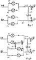
- FIG Fig. 2 An embodiment of the ventilation system according to the invention for halls, in particular for indoor swimming pools, is shown in FIG Fig. 2 similar Fig. 1 shown, so that some components are missing there.
- Fig. 2 new that one of the two air ducts of the double exhaust air fan a, b is connected to a K3 of the two air ducts of the double supply air fan c, d via a connecting duct VK in which a second air flap II is arranged.
- a third air flap purple is arranged behind the connection point.
- a fourth air flap IIIb is arranged in front of the supply air fan c in the part K3 of the supply air duct ZK which has the other connection point of the connecting duct VK.
- the fan fans of a ventilation device are usually dimensioned for outside air / exhaust air operation.
- this operating variant is only available for very few hours of operation in indoor swimming pools.
- an average circulating air volume flow is established.
- One of the weak points of the conventional flap system is that of the artificial pressure loss that the circulating air flap I creates.
- the flap I ensures permanent energy loss.
- the aim of the ventilation system according to the invention is to bypass the energetically unfavorable process management of the primary recirculation flap I.
- the new system has a connecting duct VK with a circulating air flap II, hereinafter referred to as secondary circulating air flap, and two flaps IIa, IIIb for partitioning off the circulating air fan.
- the primary recirculation flap I is preferably closed or partially or fully open, depending on the operational management.
- the new system is characterized by the fact that one of the supply air fans (in the exemplary embodiment the supply air fan c ) stands still. This fan is only necessary with very high proportions of circulating air and with 100% outside air operation. The power consumption thus decreases for the operating hours in which the circulating air components are conveyed via the secondary circulating air flap II without "throttling" the air flow.
- Another advantage is that the fans in one operating variant are not operated in series but in parallel.
- the exhaust air fans a, b are in series with the supply air fans c, d.
- the advantage is explained using an example: An operating point of 9,200 m 3 / h and 600 Pa is given. A very well designed fan achieves a static efficiency of 66.9% for this operating point. If two of these fans are arranged in series, the pressure increase for the individual fan is halved. The static efficiency drops to 62.8%. The new flap system avoids this operation with reduced efficiency.
Landscapes
- Engineering & Computer Science (AREA)
- Chemical & Material Sciences (AREA)
- Combustion & Propulsion (AREA)
- Mechanical Engineering (AREA)
- General Engineering & Computer Science (AREA)
- Life Sciences & Earth Sciences (AREA)
- Sustainable Development (AREA)
- Duct Arrangements (AREA)
- Air Conditioning Control Device (AREA)
- Ventilation (AREA)
Description
- Die Erfindung betrifft eine Anlage zum Belüften großer Räume und Hallen insbesondere von Schwimmhallen mit einem Abluftkanal mit mindestens zwei zueinander parallel angeschlossenen Abluftlüftern, mit einem Zuluftkanal in Strömungsrichtung mit mindestens zwei zueinander parallel angeschlossenen Zuluftlüftern, mit einem Umluftkanal, der den Abluftkanal in Strömungsrichtung hinter den ersten Abluftlüftern mit dem Zuluftkanal vor den Zuluftlüftern verbindet, und mit einer steuerbaren Umluftklappe im Umluftkanal.
- Bei solchen Anlagen ist es bekannt, die Abluft durch mindestens zwei parallel angeordnete Lüfter und die Zuluft durch mindestens zwei parallel angeordnete Lüfter jeweils als Doppellüfter zu bewegen und die beiden Luftströme durch einen eine Drosselklappe aufweisenden Umluftkanal zu verbinden, über den ein Teil der Abluft in das Gebäude zurückströmt, wie dies
Fig. 1 zeigt. Eine solche Belüftungsanlage bewegt große Luftmengen durch die ständig laufenden mindestens vier Lüfter. Die DruckschriftWO 2012 011 813 A2 offenbart eine Anlage gemäß dem Oberbegriff des Anspruchs 1. - Aufgabe der Erfindung ist es, eine Anlage der erfindungsgemäßen Art und das durch sie durchgeführte Verfahren so zu verbessern, dass erheblich an elektrischer Energie gespart wird, bei gleichem Wirkungsgrad und einfacher Konstruktion.
- Diese Aufgabe wird erfindungsgemäß dadurch gelöst,
- dass zwischen den Abluft- und Zuluftlüftern ein Verbindungskanal angeordnet ist, der mit einem Ende auf der Druckseite eines der beiden Lüfter des Abluftkanals und mit dem anderen Ende auf der Druckseite eines der beiden Lüfter des Zuluftkanals angeschlossen ist,
- dass im Verbindungskanal eine zweite Luftklappe angeordnet ist,
- dass in dem Teil des Abluftkanals, der die Anschlussstelle des Verbindungskanals aufweist, eine dritte Luftklappe hinter der Anschlussstelle angeordnet ist,
- dass in dem Teil des Zuluftkanals, der die andere Anschlussstelle des Verbindungskanals aufweist, eine vierte Luftklappe vor dem Zuluftlüfter angeordnet ist.
- Durch den Verbindungskanal zwischen den Abluft- und Zuluftlüftern wird eine ähnliche Wirkung erzielt wie durch den bekannten Umluftkanal zwischen dem Abluftkanal und dem Zuluftkanal. Hierbei kann aber einer der beiden Zuluftlüfter still stehen, so dass elektrische Energie erheblich eingespart wird.
- Vorzugsweise wird die erfindungsgemäße Anlage wie folgt betrieben:
- Die zweite Luftklappe wird geöffnet,
- die dritte und vierte Luftklappe werden geschlossen,
- der erste Zuluftlüfter bleibt außer Betrieb, so dass ein erheblicher Anteil der Abluft über den Verbindungskanal zum Gebäude zurückgeführt wird.
- Hierbei ist vorzugsweise die erste Umluftklappe geschlossen oder teilweise geöffnet und insbesondere geregelt. Auch kann hierbei der restliche, nicht über den Verbindungskanal strömende Teil der Abluft zum Fortluftausgang über den ersten Abluftlüfter strömen, der parallel zu dem zweiten Abluftlüfter liegt, hinter dem der Verbindungskanal abzweigt. Ferner kann hierbei die erste Umluftklappe geschlossen oder stark drosselnd eingestellt sein.
- Ausführungsbeispiele der Erfindung werden im Folgenden näher beschrieben. Es zeigen
- Fig. 1
- eine Belüftungsanlage nach dem Stand der Technik,
- Fig. 2
- eine erfindungsgemäße Version der Belüftungsanlage.
- Zum Klimatisieren großer Hallen insbesondere von Hallenbädern werden Lüftungsanlagen verwendet, die einen Abluftkanal AK und einen Zuluftkanal ZK aufweisen. Der Abluftkanal AK verbindet den Abluftausgang AB der Halle mit dem Fortluftausgang FO und der Zuluftkanal ZK verbindet den Außenlufteingang AU mit dem Zulufteingang ZU der Halle. In beiden Kanälen AK, ZK befinden sich jeweils zwei oder mehr Doppellüfter, d. h. im Abluftkanal AK sind mindestens zwei Abluftlüfter a, b zueinander parallel geschaltet und im Zuluftkanal ZK sind mindestens zwei Zuluftlüfter c, d zueinander parallel geschaltet.
- Der Abluftkanal AK ist mit dem Zuluftkanal ZK durch einen Umluftkanal UK verbunden, wobei ein Ende des Umluftkanals UK an den Abluftkanal zwischen den Abluftlüftern a, b und dem Fortluftausgang FO und das andere Ende des Umluftkanals UK an den Zuluftkanal ZK zwischen den Zuluftlüfter c, d und dem Außenlufteingang AU angeschlossen ist. Im Umluftkanal UK befindet sich eine steuerbare Umluftklappe I, durch die die Abluftmenge bestimmt wird, die zum Zuluftkanal ZK zurückströmt, so dass im normalen Betrieb oft ein erheblicher Teil der Abluft wieder benutzt wird. Ferner befindet sich im Abluftkanal AK vor dem Fortluftausgang FO und im Zuluftkanal ZK hinter dem Außenlufteingang AU jeweils eine Luftklappe IV und V.
- Solche Lüftungsanlagen sind bekannt und in
Fig. 1 schematisch dargestellt. Hierbei sind inFig. 1 und 2 aus Gründen der Übersichtlichkeit Wärmetauscher, Lufterhitzer und -kühler, Luftentfeuchtungsvorrichtungen und Filter nicht dargestellt. So sind der Abluftkanal AK mit seinem Kanalbereich X und der Zuluftkanal mit seinem Kanalbereich Y durch einen nicht dargestellten Gegenstrom- oder Kreuzstrom-Wärmetauscher hindurchgeführt. Zudem werden alle Klappen vorzugsweise durch Motoren M betätigt. - Ein Ausführungsbeispiel der erfindungsgemäßen Lüftungsanlage für Hallen insbesondere für Hallenbäder ist in
Fig. 2 ähnlichFig. 1 dargestellt, so dass dort auch einige Bauteile fehlen. Als wesentlicher Unterschied zum Stand der Technik ist bei der erfindungsgemäßen Ausführung nachFig. 2 neu, dass einer der beiden Luftkanäle des Abluftdoppellüfters a, b mit einem K3 der beiden Luftkanäle des Zuluftdoppellüfters c, d über einen Verbindungskanal VK verbunden ist, in dem eine zweite Luftklappe II angeordnet ist. Darüber hinaus ist in dem Teil K2 des Abluftkanals AK, der die Anschlussstelle des Verbindungskanals VK aufweist, eine dritte Luftklappe lila hinter der Anschlussstelle angeordnet ist. Zudem ist in dem Teil K3 des Zuluftkanals ZK, der die andere Anschlussstelle des Verbindungskanals VK aufweist, eine vierte Luftklappe IIIb vor dem Zuluftlüfter c angeordnet. - Die Lüfterventilatoren eines Lüftungsgerätes werden üblicherweise für den Außenluft-Fortluftbetrieb dimensioniert. Diese Betriebsvariante liegt in Hallenbädern allerdings nur in sehr wenigen Betriebsstunden vor. Für die Mehrheit der Betriebsstunden stellt sich ein mittlerer Umluftvolumenstrom ein. Einer der Schwachstellen des herkömmlichen Klappensystems ist der des künstlichen Druckverlustes, den die Umluftklappe I erzeugt. Die Klappe I sorgt dauerhaft für Energieverluste. Ziel der erfindungsgemäßen Belüftungsanlage ist die energetisch ungünstige Prozessführung der Primär-Umluftklappe I zu umgehen. Im Vergleich zu bekannten Anlagen kommen bei der neuen Anlage ein Verbindungskanal VK mit einer Umluftklappe II, im Folgenden Sekundär-Umluftklappe genannt, und zwei Klappen IIa, IIIb zur Abschottung des Umluftlüfter hinzu.
- Für den Fall, dass die sekundäre Luftklappe II geöffnet ist, sind die zwei Luftklappen lila, IIIb geschlossen. Außerdem ist der erste Zuluftlüfter c außer Betrieb. Dadurch drückt der Lüfter b Umluft über die sekundäre Klappe II in die Zuluft während der Lüfter a die Fortluft und Lüfter d die Außenluft fördern. Die Primär-Umluftklappe I ist je nach Betriebsführung dabei vorzugsweise geschlossen oder teilweise bis vollständig geöffnet.
- Es zeigt sich somit, dass diese Art des Umluftbetriebs ausschließlich mit zwei oder mehr Lüftern je Luftweg möglich ist. Prinzipiell sind Kombinationen aus verschiedenen Lüftern denkbar.
- Die möglichen Klappenstellungen sind wie folgt:
- Primär-Umluftklappe I: Öffnungszustand variiert stetig zwischen 0 % und 100 %
- Sekundär-Umluftklappe II: 0 % oder 100 % Öffnung
- Ventilatorklappe Abluft: 0 % oder 100 % Öffnung
- Ventilatorklappe Zuluft: 0 % oder 100 % Öffnung
- Außenluftklappe: Öffnungszustand variiert stetig zwischen 0 % und 100 %
- Fortluftklappe: Öffnungszustand variiert stetig zwischen 0 % und 100 %
- Neben dem Vorteil, dass die durch die Primär-Umluftklappe I "gedrosselte" Verbindung zwischen Druck- und Saugseite der Lüfter, bei Umluftbetrieb über die Sekundärklappe, entfällt, zeichnet sich das neue System dadurch aus, dass einer der Zuluftlüfter (im Ausführungsbeispiel der Zuluftlüfter c) stillsteht. Dieser Lüfter ist lediglich bei sehr hohen Umluftanteilen und bei 100 % Außenluftbetrieb notwendig. Somit nimmt die Aufnahmeleistung für die Betriebsstunden ab, in denen die Umluftanteile über die Sekundär-Umluftklappe II ohne "Drosselung" des Luftstromes gefördert werden.
- Ein weiterer Vorteil ist, dass die Lüfter bei einer Betriebsvariante nicht in Reihe, sondern parallel betrieben werden. Zum Vergleich, bei bekannten Anlagen befinden sich, bei geöffneter Umluftklappe I, die Abluftlüfter a, b in Reihe zu den Zuluftlüftern c, d. Der Vorteil wird anhand eines Beispiels erläutert:
Es sei ein Betriebspunkt mit 9.200 m3/h und 600 Pa gegeben. Ein sehr gut ausgelegter Lüfter erreicht für diesen Betriebspunkt einen statischen Wirkungsgrad von 66,9 %. Werden zwei dieser Lüfter in Reihe angeordnet, halbiert sich die Druckerhöhung für den einzelnen Lüfter. Der statische Wirkungsgrad fällt auf 62,8 %. Durch das neue Klappensystem wird dieser Betrieb mit reduziertem Wirkungsgrad vermieden. - In den obigen Ausführungen werden die mit "a" bis "d" bezeichneten Teile stets als "Lüfter" bezeichnet. Stattdessen können diese aber auch "Ventilator" genannt werden.
Claims (7)
- Anlage zum Belüften großer Räume und Hallen insbesondere von Schwimmhallen- mit einem Abluftkanal (AK) mit mindestens zwei zueinander parallel angeschlossenen Abluftlüftern (a, b),- mit einem Zuluftkanal (ZK) mit mindestens zwei zueinander parallel angeschlossenen Zuluftlüftern (c, d),- mit einem Umluftkanal (UK), der den Abluftkanal (AK) hinter den ersten Abluftlüftern (a, b) mit dem Zuluftkanal (ZK) vor den Zuluftlüftern (c, d) verbindet, und- mit einer steuerbaren Umluftklappe (I) im Umluftkanal (UK),
dadurch gekennzeichnet,- dass zwischen den Abluftlüftern (a, b) und Zuluftlüftern (c, d) ein Verbindungskanal (VK) angeordnet ist, der mit einem Ende auf der Druckseite eines der beiden Lüfter (b) des Abluftkanals (AK) und mit dem anderen Ende auf der Druckseite eines der beiden Lüfter (c) des Zuluftkanals (ZK) angeschlossen ist,- dass im Verbindungskanal (VK) eine zweite Luftklappe (II) angeordnet ist,- dass in dem Teil des Abluftkanals (AK), der die Anschlussstelle des Verbindungskanals (VK) aufweist, eine dritte Luftklappe (IIIa) hinter der Anschlussstelle angeordnet ist,- dass in dem Teil des Zuluftkanals (ZK), der die andere Anschlussstelle des Verbindungskanals (VK) aufweist, eine vierte Luftklappe (IIIb) vor dem Zuluftlüfter (c) angeordnet ist. - Verfahren unter Verwendung einer Anlage nach Anspruch 1 im Normalbetrieb der Anlage zum Belüften eines großen Raums insbesondere einer Halle wie einer Schwimmhalle mit folgenden Einstellungen:- die zweite Luftklappe (II) ist geöffnet,- die dritte und vierte Luftklappe (IIIa, IIIb) sind geschlossen,- der erste Zuluftlüfter (c) steht still, vor dem die vierte Luftklappe (IIIb) angeordnet ist, und- die Luftklappen und die Lüfter sind so eingestellt und gesteuert, dass der als Zuluft wiederverwendete Teil der Abluft über den Verbindungskanal (VK) zum Zulufteingang (ZE) des Raumes bzw. der Halle strömt.
- Verfahren nach Anspruch 2, dadurch gekennzeichnet, dass die erste Umluftklappe (I) geschlossen oder teilweise geöffnet ist und insbesondere geregelt wird.
- Verfahren nach Anspruch 2 oder 3, dadurch gekennzeichnet, dass der restliche, nicht über den Verbindungskanal (VK) strömende Teil der Abluft zum Fortluftausgang (FA) über den ersten Abluftlüfter (a) strömt, der parallel zu dem zweiten Abluftlüfter (b) liegt, hinter dem der Verbindungskanal (VK) abzweigt.
- Verfahren nach einem der Ansprüche 2 bis 4, dadurch gekennzeichnet, dass die erste Umluftklappe (I) geschlossen oder stark drosselnd eingestellt ist.
- Verfahren nach einem der vorherigen Ansprüche, dadurch gekennzeichnet, dass der als Außenluft dem Raum zugeführte Teil der Zuluft zum Zuluftausgang (ZU) über den zweiten Zuluftlüfter (d) strömt, der parallel zu den ersten Zuluftlüfter (c) liegt, hinter dem der Verbindungskanal (VK) mündet.
- Verfahren nach einem der vorherigen Ansprüche, dadurch gekennzeichnet, dass das die Anzahl der parallel in ZU und AB betriebenen Lüfter größer als jeweils zwei Stück ist.
Applications Claiming Priority (2)
| Application Number | Priority Date | Filing Date | Title |
|---|---|---|---|
| DE102016012269.2A DE102016012269A1 (de) | 2016-10-14 | 2016-10-14 | Belüfter großer Räume und Hallen |
| PCT/EP2017/001113 WO2018068879A1 (de) | 2016-10-14 | 2017-09-20 | BELÜFTER GROßER RÄUME UND HALLEN |
Publications (2)
| Publication Number | Publication Date |
|---|---|
| EP3500802A1 EP3500802A1 (de) | 2019-06-26 |
| EP3500802B1 true EP3500802B1 (de) | 2020-11-04 |
Family
ID=60037538
Family Applications (1)
| Application Number | Title | Priority Date | Filing Date |
|---|---|---|---|
| EP17780623.9A Not-in-force EP3500802B1 (de) | 2016-10-14 | 2017-09-20 | Belüfter grosser räume und hallen |
Country Status (3)
| Country | Link |
|---|---|
| EP (1) | EP3500802B1 (de) |
| DE (1) | DE102016012269A1 (de) |
| WO (1) | WO2018068879A1 (de) |
Families Citing this family (2)
| Publication number | Priority date | Publication date | Assignee | Title |
|---|---|---|---|---|
| US11371728B2 (en) | 2018-12-04 | 2022-06-28 | Lennox Industries Inc. | Method and system for utilizing a bypass humidifier for dehumidification during cooling |
| US10955165B2 (en) * | 2018-12-04 | 2021-03-23 | Lennox Industries Inc. | Method and system for supply-air re-circulation |
Family Cites Families (4)
| Publication number | Priority date | Publication date | Assignee | Title |
|---|---|---|---|---|
| DE3148357A1 (de) * | 1981-12-07 | 1983-06-09 | Wilhelm Gebhardt Gmbh, 7112 Waldenburg | Zum beispiel in verbindung mit klimaanlagen zu verwendende geblaeseanordnung und mit einer solchen geblaeseanordnung ausgeruestete klimaanlage |
| DE4343611C2 (de) * | 1992-12-16 | 1998-04-09 | Hansa Ventilatoren Masch | Klimagerät |
| JPH09159207A (ja) * | 1995-12-07 | 1997-06-20 | Toshiba Corp | 中央制御室換気空調設備 |
| NL2005138C2 (en) * | 2010-07-23 | 2012-01-24 | Deerns Raadgevende Ingenieurs B V | Apparatus and method for cooling a substantially closed space. |
-
2016
- 2016-10-14 DE DE102016012269.2A patent/DE102016012269A1/de not_active Withdrawn
-
2017
- 2017-09-20 WO PCT/EP2017/001113 patent/WO2018068879A1/de not_active Ceased
- 2017-09-20 EP EP17780623.9A patent/EP3500802B1/de not_active Not-in-force
Non-Patent Citations (1)
| Title |
|---|
| None * |
Also Published As
| Publication number | Publication date |
|---|---|
| DE102016012269A1 (de) | 2018-04-19 |
| WO2018068879A1 (de) | 2018-04-19 |
| EP3500802A1 (de) | 2019-06-26 |
Similar Documents
| Publication | Publication Date | Title |
|---|---|---|
| DE102008029922B4 (de) | Raumlufttechnisches Gerät | |
| DE4002560A1 (de) | Klimageraet | |
| EP2246634B1 (de) | Direkte freie Kühlung | |
| DE102007010268A1 (de) | Mischvorrichtung für Flugzeugklimaanlage | |
| DE102007049333A1 (de) | Klimaanlage, insbesondere für Schiffe | |
| DE102014221143B4 (de) | Fahrzeugkühlanlage und zugehöriges Betriebsverfahren | |
| DE202012010671U1 (de) | Lufttechnisches Gerät zur Be- und Entlüftung | |
| AT394263B (de) | Geblaeseanordnung | |
| DE202007001644U1 (de) | Modular aufgebaute Lüftungseinrichtung für den Einsatz im Reinraum | |
| WO2018068879A1 (de) | BELÜFTER GROßER RÄUME UND HALLEN | |
| EP2250444B1 (de) | Zwei kanal-klimaanlage zur flexiblen klimatisierung einer anzahl von räumen | |
| DE102014209452B4 (de) | Klimaanlage mit Bypassvorrichtung und Verfahren | |
| DE102011000525A1 (de) | Verfahren zum Betreiben einer Lüftungsanlage mit einer Mischkammer | |
| DE102010010711A1 (de) | Verfahren und Vorrichtung zum Lüften eines Objekts | |
| DE102015001845A1 (de) | Raumlufttechnisches Gerät sowie Verfahren zum Kühlen eines Rechenzentrums | |
| DE212020000567U1 (de) | Gesteuertes mechanisches Ventilationssystem mit Luftmischeinheit | |
| DE102007033055B4 (de) | Raumlufttechnisches Gerät | |
| DE102006007848B4 (de) | Anlage zum Erwärmen einer Einrichtung wie einer Halle mit hohem Temperaturniveau, die entfeuchtet werden muss, insbesondere einer Schwimmhalle | |
| DE202013102473U1 (de) | Raumlufttechnisches (RLT) Gerät für eine zentrale RLT Anlage | |
| DE20209031U1 (de) | Belüftungssystem zur Raumbe- und -entlüftung | |
| DE202004018206U1 (de) | Gerät zur Klimatisierung, wie Entfeuchter, Klimagerät, Lüftungsgerät u.dgl. | |
| DE9218368U1 (de) | Klimagerät | |
| DE102015118329B4 (de) | Verfahren zur Kühlung von Rechenzentren | |
| WO1995018944A1 (de) | Klima-gerät mit redundantventilator | |
| DE102017202250A1 (de) | Klimagerät |
Legal Events
| Date | Code | Title | Description |
|---|---|---|---|
| STAA | Information on the status of an ep patent application or granted ep patent |
Free format text: STATUS: UNKNOWN |
|
| STAA | Information on the status of an ep patent application or granted ep patent |
Free format text: STATUS: THE INTERNATIONAL PUBLICATION HAS BEEN MADE |
|
| PUAI | Public reference made under article 153(3) epc to a published international application that has entered the european phase |
Free format text: ORIGINAL CODE: 0009012 |
|
| STAA | Information on the status of an ep patent application or granted ep patent |
Free format text: STATUS: REQUEST FOR EXAMINATION WAS MADE |
|
| 17P | Request for examination filed |
Effective date: 20190320 |
|
| AK | Designated contracting states |
Kind code of ref document: A1 Designated state(s): AL AT BE BG CH CY CZ DE DK EE ES FI FR GB GR HR HU IE IS IT LI LT LU LV MC MK MT NL NO PL PT RO RS SE SI SK SM TR |
|
| AX | Request for extension of the european patent |
Extension state: BA ME |
|
| DAV | Request for validation of the european patent (deleted) | ||
| DAX | Request for extension of the european patent (deleted) | ||
| REG | Reference to a national code |
Ref country code: DE Ref legal event code: R079 Ref document number: 502017008080 Country of ref document: DE Free format text: PREVIOUS MAIN CLASS: F24F0007007000 Ipc: F24F0005000000 |
|
| GRAP | Despatch of communication of intention to grant a patent |
Free format text: ORIGINAL CODE: EPIDOSNIGR1 |
|
| STAA | Information on the status of an ep patent application or granted ep patent |
Free format text: STATUS: GRANT OF PATENT IS INTENDED |
|
| RIC1 | Information provided on ipc code assigned before grant |
Ipc: F24F 11/00 20180101ALI20200428BHEP Ipc: F24F 3/044 20060101ALI20200428BHEP Ipc: F24F 5/00 20060101AFI20200428BHEP Ipc: F24F 7/08 20060101ALI20200428BHEP Ipc: F24F 13/14 20060101ALI20200428BHEP Ipc: F24F 13/02 20060101ALI20200428BHEP |
|
| INTG | Intention to grant announced |
Effective date: 20200514 |
|
| GRAS | Grant fee paid |
Free format text: ORIGINAL CODE: EPIDOSNIGR3 |
|
| GRAA | (expected) grant |
Free format text: ORIGINAL CODE: 0009210 |
|
| STAA | Information on the status of an ep patent application or granted ep patent |
Free format text: STATUS: THE PATENT HAS BEEN GRANTED |
|
| AK | Designated contracting states |
Kind code of ref document: B1 Designated state(s): AL AT BE BG CH CY CZ DE DK EE ES FI FR GB GR HR HU IE IS IT LI LT LU LV MC MK MT NL NO PL PT RO RS SE SI SK SM TR |
|
| REG | Reference to a national code |
Ref country code: GB Ref legal event code: FG4D Free format text: NOT ENGLISH |
|
| REG | Reference to a national code |
Ref country code: CH Ref legal event code: EP |
|
| REG | Reference to a national code |
Ref country code: AT Ref legal event code: REF Ref document number: 1331337 Country of ref document: AT Kind code of ref document: T Effective date: 20201115 |
|
| REG | Reference to a national code |
Ref country code: DE Ref legal event code: R096 Ref document number: 502017008080 Country of ref document: DE |
|
| REG | Reference to a national code |
Ref country code: IE Ref legal event code: FG4D Free format text: LANGUAGE OF EP DOCUMENT: GERMAN |
|
| REG | Reference to a national code |
Ref country code: NL Ref legal event code: MP Effective date: 20201104 |
|
| PG25 | Lapsed in a contracting state [announced via postgrant information from national office to epo] |
Ref country code: FI Free format text: LAPSE BECAUSE OF FAILURE TO SUBMIT A TRANSLATION OF THE DESCRIPTION OR TO PAY THE FEE WITHIN THE PRESCRIBED TIME-LIMIT Effective date: 20201104 Ref country code: RS Free format text: LAPSE BECAUSE OF FAILURE TO SUBMIT A TRANSLATION OF THE DESCRIPTION OR TO PAY THE FEE WITHIN THE PRESCRIBED TIME-LIMIT Effective date: 20201104 Ref country code: PT Free format text: LAPSE BECAUSE OF FAILURE TO SUBMIT A TRANSLATION OF THE DESCRIPTION OR TO PAY THE FEE WITHIN THE PRESCRIBED TIME-LIMIT Effective date: 20210304 Ref country code: GR Free format text: LAPSE BECAUSE OF FAILURE TO SUBMIT A TRANSLATION OF THE DESCRIPTION OR TO PAY THE FEE WITHIN THE PRESCRIBED TIME-LIMIT Effective date: 20210205 Ref country code: NO Free format text: LAPSE BECAUSE OF FAILURE TO SUBMIT A TRANSLATION OF THE DESCRIPTION OR TO PAY THE FEE WITHIN THE PRESCRIBED TIME-LIMIT Effective date: 20210204 |
|
| PG25 | Lapsed in a contracting state [announced via postgrant information from national office to epo] |
Ref country code: ES Free format text: LAPSE BECAUSE OF FAILURE TO SUBMIT A TRANSLATION OF THE DESCRIPTION OR TO PAY THE FEE WITHIN THE PRESCRIBED TIME-LIMIT Effective date: 20201104 Ref country code: SE Free format text: LAPSE BECAUSE OF FAILURE TO SUBMIT A TRANSLATION OF THE DESCRIPTION OR TO PAY THE FEE WITHIN THE PRESCRIBED TIME-LIMIT Effective date: 20201104 Ref country code: IS Free format text: LAPSE BECAUSE OF FAILURE TO SUBMIT A TRANSLATION OF THE DESCRIPTION OR TO PAY THE FEE WITHIN THE PRESCRIBED TIME-LIMIT Effective date: 20210304 Ref country code: PL Free format text: LAPSE BECAUSE OF FAILURE TO SUBMIT A TRANSLATION OF THE DESCRIPTION OR TO PAY THE FEE WITHIN THE PRESCRIBED TIME-LIMIT Effective date: 20201104 Ref country code: LV Free format text: LAPSE BECAUSE OF FAILURE TO SUBMIT A TRANSLATION OF THE DESCRIPTION OR TO PAY THE FEE WITHIN THE PRESCRIBED TIME-LIMIT Effective date: 20201104 Ref country code: BG Free format text: LAPSE BECAUSE OF FAILURE TO SUBMIT A TRANSLATION OF THE DESCRIPTION OR TO PAY THE FEE WITHIN THE PRESCRIBED TIME-LIMIT Effective date: 20210204 |
|
| REG | Reference to a national code |
Ref country code: LT Ref legal event code: MG9D |
|
| PG25 | Lapsed in a contracting state [announced via postgrant information from national office to epo] |
Ref country code: HR Free format text: LAPSE BECAUSE OF FAILURE TO SUBMIT A TRANSLATION OF THE DESCRIPTION OR TO PAY THE FEE WITHIN THE PRESCRIBED TIME-LIMIT Effective date: 20201104 |
|
| PG25 | Lapsed in a contracting state [announced via postgrant information from national office to epo] |
Ref country code: RO Free format text: LAPSE BECAUSE OF FAILURE TO SUBMIT A TRANSLATION OF THE DESCRIPTION OR TO PAY THE FEE WITHIN THE PRESCRIBED TIME-LIMIT Effective date: 20201104 Ref country code: SK Free format text: LAPSE BECAUSE OF FAILURE TO SUBMIT A TRANSLATION OF THE DESCRIPTION OR TO PAY THE FEE WITHIN THE PRESCRIBED TIME-LIMIT Effective date: 20201104 Ref country code: SM Free format text: LAPSE BECAUSE OF FAILURE TO SUBMIT A TRANSLATION OF THE DESCRIPTION OR TO PAY THE FEE WITHIN THE PRESCRIBED TIME-LIMIT Effective date: 20201104 Ref country code: CZ Free format text: LAPSE BECAUSE OF FAILURE TO SUBMIT A TRANSLATION OF THE DESCRIPTION OR TO PAY THE FEE WITHIN THE PRESCRIBED TIME-LIMIT Effective date: 20201104 Ref country code: EE Free format text: LAPSE BECAUSE OF FAILURE TO SUBMIT A TRANSLATION OF THE DESCRIPTION OR TO PAY THE FEE WITHIN THE PRESCRIBED TIME-LIMIT Effective date: 20201104 Ref country code: LT Free format text: LAPSE BECAUSE OF FAILURE TO SUBMIT A TRANSLATION OF THE DESCRIPTION OR TO PAY THE FEE WITHIN THE PRESCRIBED TIME-LIMIT Effective date: 20201104 |
|
| REG | Reference to a national code |
Ref country code: DE Ref legal event code: R097 Ref document number: 502017008080 Country of ref document: DE |
|
| PG25 | Lapsed in a contracting state [announced via postgrant information from national office to epo] |
Ref country code: DK Free format text: LAPSE BECAUSE OF FAILURE TO SUBMIT A TRANSLATION OF THE DESCRIPTION OR TO PAY THE FEE WITHIN THE PRESCRIBED TIME-LIMIT Effective date: 20201104 |
|
| PLBE | No opposition filed within time limit |
Free format text: ORIGINAL CODE: 0009261 |
|
| STAA | Information on the status of an ep patent application or granted ep patent |
Free format text: STATUS: NO OPPOSITION FILED WITHIN TIME LIMIT |
|
| 26N | No opposition filed |
Effective date: 20210805 |
|
| PG25 | Lapsed in a contracting state [announced via postgrant information from national office to epo] |
Ref country code: AL Free format text: LAPSE BECAUSE OF FAILURE TO SUBMIT A TRANSLATION OF THE DESCRIPTION OR TO PAY THE FEE WITHIN THE PRESCRIBED TIME-LIMIT Effective date: 20201104 Ref country code: NL Free format text: LAPSE BECAUSE OF FAILURE TO SUBMIT A TRANSLATION OF THE DESCRIPTION OR TO PAY THE FEE WITHIN THE PRESCRIBED TIME-LIMIT Effective date: 20201104 Ref country code: IT Free format text: LAPSE BECAUSE OF FAILURE TO SUBMIT A TRANSLATION OF THE DESCRIPTION OR TO PAY THE FEE WITHIN THE PRESCRIBED TIME-LIMIT Effective date: 20201104 |
|
| PG25 | Lapsed in a contracting state [announced via postgrant information from national office to epo] |
Ref country code: SI Free format text: LAPSE BECAUSE OF FAILURE TO SUBMIT A TRANSLATION OF THE DESCRIPTION OR TO PAY THE FEE WITHIN THE PRESCRIBED TIME-LIMIT Effective date: 20201104 |
|
| REG | Reference to a national code |
Ref country code: DE Ref legal event code: R119 Ref document number: 502017008080 Country of ref document: DE |
|
| REG | Reference to a national code |
Ref country code: CH Ref legal event code: PL |
|
| REG | Reference to a national code |
Ref country code: BE Ref legal event code: MM Effective date: 20210930 |
|
| GBPC | Gb: european patent ceased through non-payment of renewal fee |
Effective date: 20210920 |
|
| PG25 | Lapsed in a contracting state [announced via postgrant information from national office to epo] |
Ref country code: IS Free format text: LAPSE BECAUSE OF FAILURE TO SUBMIT A TRANSLATION OF THE DESCRIPTION OR TO PAY THE FEE WITHIN THE PRESCRIBED TIME-LIMIT Effective date: 20210304 Ref country code: MC Free format text: LAPSE BECAUSE OF FAILURE TO SUBMIT A TRANSLATION OF THE DESCRIPTION OR TO PAY THE FEE WITHIN THE PRESCRIBED TIME-LIMIT Effective date: 20201104 |
|
| PG25 | Lapsed in a contracting state [announced via postgrant information from national office to epo] |
Ref country code: LU Free format text: LAPSE BECAUSE OF NON-PAYMENT OF DUE FEES Effective date: 20210920 Ref country code: IE Free format text: LAPSE BECAUSE OF NON-PAYMENT OF DUE FEES Effective date: 20210920 Ref country code: GB Free format text: LAPSE BECAUSE OF NON-PAYMENT OF DUE FEES Effective date: 20210920 Ref country code: FR Free format text: LAPSE BECAUSE OF NON-PAYMENT OF DUE FEES Effective date: 20210930 Ref country code: DE Free format text: LAPSE BECAUSE OF NON-PAYMENT OF DUE FEES Effective date: 20220401 Ref country code: BE Free format text: LAPSE BECAUSE OF NON-PAYMENT OF DUE FEES Effective date: 20210930 |
|
| PG25 | Lapsed in a contracting state [announced via postgrant information from national office to epo] |
Ref country code: LI Free format text: LAPSE BECAUSE OF NON-PAYMENT OF DUE FEES Effective date: 20210930 Ref country code: CH Free format text: LAPSE BECAUSE OF NON-PAYMENT OF DUE FEES Effective date: 20210930 |
|
| PG25 | Lapsed in a contracting state [announced via postgrant information from national office to epo] |
Ref country code: CY Free format text: LAPSE BECAUSE OF FAILURE TO SUBMIT A TRANSLATION OF THE DESCRIPTION OR TO PAY THE FEE WITHIN THE PRESCRIBED TIME-LIMIT Effective date: 20201104 |
|
| PG25 | Lapsed in a contracting state [announced via postgrant information from national office to epo] |
Ref country code: HU Free format text: LAPSE BECAUSE OF FAILURE TO SUBMIT A TRANSLATION OF THE DESCRIPTION OR TO PAY THE FEE WITHIN THE PRESCRIBED TIME-LIMIT; INVALID AB INITIO Effective date: 20170920 |
|
| REG | Reference to a national code |
Ref country code: AT Ref legal event code: MM01 Ref document number: 1331337 Country of ref document: AT Kind code of ref document: T Effective date: 20220920 |
|
| PG25 | Lapsed in a contracting state [announced via postgrant information from national office to epo] |
Ref country code: AT Free format text: LAPSE BECAUSE OF NON-PAYMENT OF DUE FEES Effective date: 20220920 |
|
| PG25 | Lapsed in a contracting state [announced via postgrant information from national office to epo] |
Ref country code: MK Free format text: LAPSE BECAUSE OF FAILURE TO SUBMIT A TRANSLATION OF THE DESCRIPTION OR TO PAY THE FEE WITHIN THE PRESCRIBED TIME-LIMIT Effective date: 20201104 |
|
| PG25 | Lapsed in a contracting state [announced via postgrant information from national office to epo] |
Ref country code: MT Free format text: LAPSE BECAUSE OF FAILURE TO SUBMIT A TRANSLATION OF THE DESCRIPTION OR TO PAY THE FEE WITHIN THE PRESCRIBED TIME-LIMIT Effective date: 20201104 |
|
| PG25 | Lapsed in a contracting state [announced via postgrant information from national office to epo] |
Ref country code: TR Free format text: LAPSE BECAUSE OF FAILURE TO SUBMIT A TRANSLATION OF THE DESCRIPTION OR TO PAY THE FEE WITHIN THE PRESCRIBED TIME-LIMIT Effective date: 20201104 |