EP3501249B1 - A method for operating an agricultural machine and agricultural machine - Google Patents
A method for operating an agricultural machine and agricultural machine Download PDFInfo
- Publication number
- EP3501249B1 EP3501249B1 EP17209874.1A EP17209874A EP3501249B1 EP 3501249 B1 EP3501249 B1 EP 3501249B1 EP 17209874 A EP17209874 A EP 17209874A EP 3501249 B1 EP3501249 B1 EP 3501249B1
- Authority
- EP
- European Patent Office
- Prior art keywords
- working
- working space
- electric load
- condition
- electric
- Prior art date
- Legal status (The legal status is an assumption and is not a legal conclusion. Google has not performed a legal analysis and makes no representation as to the accuracy of the status listed.)
- Active
Links
Images

Classifications
-
- A—HUMAN NECESSITIES
- A01—AGRICULTURE; FORESTRY; ANIMAL HUSBANDRY; HUNTING; TRAPPING; FISHING
- A01B—SOIL WORKING IN AGRICULTURE OR FORESTRY; PARTS, DETAILS, OR ACCESSORIES OF AGRICULTURAL MACHINES OR IMPLEMENTS, IN GENERAL
- A01B79/00—Methods for working soil
- A01B79/02—Methods for working soil combined with other agricultural processing, e.g. fertilising, planting
-
- A—HUMAN NECESSITIES
- A01—AGRICULTURE; FORESTRY; ANIMAL HUSBANDRY; HUNTING; TRAPPING; FISHING
- A01B—SOIL WORKING IN AGRICULTURE OR FORESTRY; PARTS, DETAILS, OR ACCESSORIES OF AGRICULTURAL MACHINES OR IMPLEMENTS, IN GENERAL
- A01B71/00—Construction or arrangement of setting or adjusting mechanisms, of implement or tool drive or of power take-off; Means for protecting parts against dust, or the like; Adapting machine elements to or for agricultural purposes
- A01B71/02—Setting or adjusting mechanisms
Definitions
- the present invention refers to a method for operating an agricultural machine and an agricultural machine.
- agricultural application machines are provided for applying or dispensing a granular material, a liquid material or a powder-form material.
- a spreader may be used for dispensing a granular material or a powder-form material.
- a liquid material may be applied by a sprayer.
- a seeder is an agricultural machine for applying a granular material, namely seeds.
- Another type of an agricultural machine is a mower configured to cut grass or other plants that grow on soil.
- Document US 3,906,710 discloses an automatic height-of-cut control for a crop harvesting implement such as a swather comprising a sensor disposed behind the cutting bar for indicating the cut crop material length.
- the sensor is positioned by a cable and pulley mechanism in relation to the cutting bar height such that for positions of the cutting bar there is a corresponding sensor position providing a preselected stubble to crop height ratio.
- a controller filters the sensor output which positions an electrohydraulic valve to either raise, lower or maintain the swather table by means of a hydraulic actuator.
- Document EP 3 042 555 A1 refers to the field of seeders.
- a movable member can be relocated with respect to a seeder disc, thereby, providing different lines of movement for seeds ejected by the seeder disc through the movable member.
- Document CN 10 7390620 refers to an agricultural work machine, comprising an automatic work control unit.
- the automatic work control unit has a system management module, a memory module, a human-machine interaction module, an interpolation module, a PLC function module, a position control module, a system bus, a work work program automatic generation module, a work tool device control module, and a communication module.
- An electrical logic control unit has a CPU, a RAM, a ROM, and an input and output interface circuit. The electrical logic control unit internally adopts a bus structure. The bus is used for transmitting data information, address information, and control information.
- a driving unit includes: a position control unit, a speed control unit, a detection and feedback unit, and a driving unit.
- An agricultural work machine mechanical structure main body has front and rear (Y-axis) motion driving devices, upper and lower (Z-axis) lifting driving devices, left and right (X-axis) motion driving devices, rotary driving devices, and working tool device clamping and placing devices.
- the working tool device has a grip handle, a workman equipment racks and work tool.
- Document WO 98 / 04112 A2 discloses a mowing machine, comprising a cutter bar, a crushing device including a rotor provided with crushing elements, and adjusting means by means of which the distance between the crushing elements and the cutter bar can be adjusted.
- the mowing machine further comprises measuring means with the aid of which it is possible to determine the number of revolutions and / or the force by which the crushing device is driven.
- the mowing machine further comprises a control mechanism for activating the adjusting means on the basis of the signals supplied by the measuring means.
- the working space may be referred to as an area of activity of a working tool of the working device.
- the working space may be the space to which the material to be applied is dispensed.
- the working tool can be operated by driving the working device.
- the determining may refers to measuring or detecting, by the control unit, the first and second electric load supplied to the electric drive.
- Electric energy may be provided to the electric drive by a power supply provided on a tractor or an implement trailed or carried by the tractor.
- the agricultural machine alternatively, may be provided as a self-propelling machine.
- the information gathered by determining the first and second electric load may be used in a process of observing operation of the agricultural machine.
- the information about the first and second electric load may be used for controlling any function of the agricultural machine in response to determining at least one of the first and second electric loads.
- a mode of operation for the tractor and / or the implement trailed or carried by the tractor may be controlled in response to determining at least one of the first and second electric load supplied to the electric drive.
- the electric power provided to the electric drive may comprise at least one of AC voltage and DC voltage.
- the forming of the second working space may comprise reducing the first working space to the second working space reduced compared to the first working space.
- the forming of the second working space may comprise expanding the first working space to the second working space expanded or being wider compared to the first working space.
- the second working space may cover a spatial room bigger than the first working space.
- the second working space may cover an area in a working plane different from the first working space.
- the method further comprises: determining a first working space condition from the first electric load indicative of the first working space condition; and determining a second working space condition from the second electric load indicative of the second working space condition.
- the first work space condition may be an overload condition. If, by the working device, a granular or a liquid material is dispensed, the overload condition may indicate too much material dispensed into the working space at a given point of time. For example, there may be too much of the liquid or granular material in the working space causing a higher electric load to the working device.
- the second working space condition may indicate a non-overload condition. In such case the second electric load may be below a threshold electric load, thereby, indicating that there is not too much material dispensed to the working space.
- the method may further comprise positioning the shaping member in a third position relative to the working device in response to determining the first working space condition or the second working space condition, the third positon being different from the first and second positions. If it is determined that the first or the second working space condition is present, the shaping member is moved to a different position, for example, for reducing or eliminating an overload condition with regard to the working space.
- the first or the second electric load supplied to the electric drive may indicate a condition of congestion in the working space. Moving the shaping member to the third position may provide for reducing or eliminating the congestion. Such mode of congestion may be indicated by the electric load supplied to the electric drive being above a threshold value.
- the method may further comprise operating the electric device with a third electric load different from the first and second electric load.
- the electric load provided to the electric drive may be increased or decreased, thereby, providing the third electric load.
- the method may further comprise determining at least one of determining a first position value for the first position of the shaping device from the first electric load indicative of the first position; and determining a second position value for the second position of the shaping device from the second electric load indicative of the second position.
- the first or second position values may indicate a distance between the shaping member and some reference point, for example, a reference point on the working device.
- the first and second position values may be indicative of a positional height of the shaping member.
- a spatial position of the shaping member may be indicated by the first and second position values. It may be further provided to position the shaping member in a third position relative to the working position in response to determining the first position value or the second position value.
- the method may further comprise comparing at least one of the first electric load and the second electric load to reference electric load data, the reference electric load data being assigned to least one of the following: the first work space condition, the second work space condition, the first position value, and the second position value.
- the electric load measured or detected while the working device is driven by the electric drive is compared to reference electric load data which in turn are assigned to different conditions or values.
- a present electric load detected or measured can be assigned to some condition and / or position value.
- a present position of the shaping member is determined from the information about the first and / or the second electric load supplied to the electric drive.
- the method may further comprise providing the working device with a spreader device configured to dispense a granular material; and driving the spreader device by the electric drive.
- the spreader may be a disc spreader.
- the shaping member may be provided with a plate member, for example a border plate.
- the plate member for example, is movable relative to the spreader device for shaping or conditioning the area or the space provided for the working space.
- the plate member may be used to limit the working space if the spreader or sprayer comprising the spreader device and the sprayer device, respectively, is moving along a border of a field to which the granular / liquid material is dispensed.
- the area or the space (working space) to which the granular or liquid material is dispensed is shaped or conditioned.
- the electric load of the electric drive will vary because of providing different conditions for the dispensing process.
- the electric load measured for the electric drive may be indicative of the positioning of the plate member relative to the spreader device or the sprayer device.
- the method may further comprise providing the working device with a sprayer device configured to dispense a liquid material; and driving the sprayer device by the electric drive.
- the sprayer device may be provided with a nozzle for dispensing the liquid material.
- the method may further comprise: providing the working device with a cutting device configured to cut grass or other plant; and driving the cutting device by the electric drive.
- the cutting device may be provided on a mower.
- a shaping device may be provided with a plate such a movable cover plate positioned for shaping the working space, such working space allowing free movement of a cutting tool of a cutting device, for example free rotation in the process of cutting grass or other plants.
- the method may further comprise positioning a swath forming member in an operation position in response to determining at least one of the first working space condition, the second working space condition, the first position value, and the second position value.
- the swath forming member may be pivotably or movably mounted on a mower, the swath forming member being configured to form a swath from crop cut by the cutting device.
- the swath forming process may be controlled by controlling positioning of the swath forming member, the swath forming member being moved to different operation positions.
- the method may further comprise providing the working device with a seeder device configured to dispense seeds; and driving the seeder device by the electric drive.
- the shaping member may be provided with a plate configured to additional guide seeds dispensed from an opening of the seeder device.
- the agricultural machine may be an agricultural application machine such as spreader, sprayer, mower or seeder.
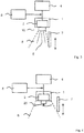
- Fig. 1 shows a schematic representation of an arrangement for an agricultural machine provided with a working device 1 which is a spreader device in the embodiment shown.
- the working device 1 is assigned an electric drive 2 such as an electric motor configured to drive the working device 1.
- a working tool 3 of the working device 1 is driven by the electric drive 2.
- the working device 3 may be provided with a disc spreader driven by the electric drive 2 for applying or dispensing some material.
- Electric energy is supplied to the electric drive 2 by a power supply 4 provided, for example, on a tractor or an implement trailed or carried by the tractor, the implement comprising the working device 1.
- AC or DC voltage may be provided to the working device 1.
- the working device 1 is dispensing a granular material 5 into a working space 6 assigned to the working device 1.
- a shaping member 7 is provided, for example a plate member, for conditioning or shaping the working space 6 on at least one side. Depending on the position of the shaping member 7 relative to the working device 1 there are differently shaped or conditioned forms of the working space 6 (see Figs. 1 and 2 ). In an alternative embodiment more than one shaping member may be provided.
- the electric load supplied to or needed by the electric drive 2 will be different.
- Such different electric loads are detected by a control unit 8.
- the electric loads measured by the control unit 8 are compared to reference electric load data provided, for example, in a memory of the control unit 8, for assigning a measured electric load to a reference electric load.
- the reference electric load is assigned to a working space condition.
- the reference electric load may be assigned to a position value indicative of the position of the shaping member 7.
- Fig. 3 shows a schematic representation of an arrangement for an agricultural machine in which the working device 1 is provided with a sprayer device 10 configured to dispense some liquid material.
- the arrangement from Fig. 3 may be provided in an agricultural sprayer.
- the embodiments described above with regard to the arrangement in Fig. 1 and 2 apply to the arrangement in Fig. 3 mutatis mutandis.
- Fig. 4 shows a schematic representation of an arrangement in which the working device 1 is provided with a cutting device 20 configured to cut grass or other grown plants.
- the arrangement may be provided in a mower.
- the shaping member 7 is positioned in the vicinity of the cutting device 20, thereby, shaping the working space 6.
- the electric load to the cutting device 20 may depend, for example, on some congestion condition or non-congestion condition with regard to the working space 6 indicating the working space 6 covered or congested by crop more or less.
- the electric load will increase indicating a position of the shaping member 7 limiting the working space 6 too much.
- the shaping member 7 may be moved in a position (e.g. moving up) providing a wider working space 6 for the cutting device 20.
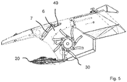
- Fig. 5 shows a schematic representation of another arrangement comprising a cutting device 20 for a mower. Crop cut will be conditioned by a conditioner 30. The working space 6 assigned to the conditioner 30 can be adjusted by the shaping member 7 provided with a conditioner plate 40 pivotable.
Landscapes
- Life Sciences & Earth Sciences (AREA)
- Engineering & Computer Science (AREA)
- Mechanical Engineering (AREA)
- Soil Sciences (AREA)
- Environmental Sciences (AREA)
- Harvester Elements (AREA)
- Catching Or Destruction (AREA)
- Fertilizing (AREA)
- Agricultural Machines (AREA)
- Soil Working Implements (AREA)
Priority Applications (2)
| Application Number | Priority Date | Filing Date | Title |
|---|---|---|---|
| EP17209874.1A EP3501249B1 (en) | 2017-12-21 | 2017-12-21 | A method for operating an agricultural machine and agricultural machine |
| DK17209874.1T DK3501249T3 (da) | 2017-12-21 | 2017-12-21 | Fremgangsmåde til at betjene en landbrugsmaskine og landbrugsmaskine |
Applications Claiming Priority (1)
| Application Number | Priority Date | Filing Date | Title |
|---|---|---|---|
| EP17209874.1A EP3501249B1 (en) | 2017-12-21 | 2017-12-21 | A method for operating an agricultural machine and agricultural machine |
Publications (2)
| Publication Number | Publication Date |
|---|---|
| EP3501249A1 EP3501249A1 (en) | 2019-06-26 |
| EP3501249B1 true EP3501249B1 (en) | 2021-10-27 |
Family
ID=60813636
Family Applications (1)
| Application Number | Title | Priority Date | Filing Date |
|---|---|---|---|
| EP17209874.1A Active EP3501249B1 (en) | 2017-12-21 | 2017-12-21 | A method for operating an agricultural machine and agricultural machine |
Country Status (2)
| Country | Link |
|---|---|
| EP (1) | EP3501249B1 (da) |
| DK (1) | DK3501249T3 (da) |
Family Cites Families (5)
| Publication number | Priority date | Publication date | Assignee | Title |
|---|---|---|---|---|
| US3906710A (en) * | 1974-03-25 | 1975-09-23 | Canadian Patents Dev | Height-of-cut control for a crop harvesting implement |
| JPH11512936A (ja) * | 1996-07-29 | 1999-11-09 | マースランド エヌ・ヴィ | 刈り取り機 |
| US20060123764A1 (en) * | 2004-12-09 | 2006-06-15 | Mclean Kenneth W | Adjustable windrower shields |
| DK3042555T3 (da) * | 2015-01-07 | 2017-11-13 | Kverneland As | Så-skær med indstilleligt skærhoved |
| CN107390620A (zh) * | 2017-07-17 | 2017-11-24 | 杨新高 | 农业作业机系统 |
-
2017
- 2017-12-21 DK DK17209874.1T patent/DK3501249T3/da active
- 2017-12-21 EP EP17209874.1A patent/EP3501249B1/en active Active
Also Published As
| Publication number | Publication date |
|---|---|
| EP3501249A1 (en) | 2019-06-26 |
| DK3501249T3 (da) | 2022-01-10 |
Similar Documents
| Publication | Publication Date | Title |
|---|---|---|
| US20220142040A1 (en) | System and method for controlling the operation of a residue removal device of a seed-planting implement based on a residue characteristic of the field | |
| EP3165062B1 (de) | Landwirtschaftliche arbeitsmaschine mit einer umfelddetektionseinrichtung | |
| EP0702891B1 (de) | Mähdrescherbetrieb mit Betriebsdatenkataster | |
| DE69109659T2 (de) | Messvorrichtung für erntegut. | |
| CA2704416C (en) | Depth adjustment of trailing arm furrow openers | |
| EP2517543B1 (de) | Landwirtschaftliche Maschine | |
| EP2042276A2 (de) | Landwirtschaftliche Maschine und Verfahren zur Positionsbestimmung | |
| US9179600B2 (en) | Mower-conditioner header speed control based on forward travel speed | |
| EP3858130B1 (en) | Multi mode crop forming shield adjustment mechanism | |
| EP3494768A1 (de) | Verfahren und vorrichtung zur kartierung eventuell in einem feld vorhandener fremdkörper | |
| EP4030888B1 (de) | Schneidwerk mit sensoren zur höhenregelung | |
| DE112005002991T5 (de) | Arbeitsmaschinenbetriebssystem und -verfahren | |
| EP1374661A1 (de) | Vorrichtung und Verfahren zur Lagesteuerung eines Erntegutaufnahmegerätes landwirtschaftlicher Erntemaschinen | |
| EP3451818B1 (en) | Conditioner unit | |
| EP3967119B1 (en) | Auto-positioning camera for drawn implements | |
| DE19623754A1 (de) | Erntemaschine mit einem in seiner Arbeitslage gegenüber dem Boden höhenverstellbaren Vorsatzbearbeitungsgerät | |
| EP2436259A1 (de) | Aufbereitungseinrichtung mit elektronischer Steuereinrichtung für eine landwirtschaftliche Arbeitsmaschine | |
| CN104247606A (zh) | 包括用于提升作业工具高度的伺服控制装置的收割机 | |
| EP2733680A1 (de) | Verfahren zum Betreiben einer selbstfahrenden Erntemaschine | |
| EP2361496A1 (en) | Combined, bilateral, adjustable agricultural tool platform | |
| SE530382C2 (sv) | Anordning för styrning och/eller reglering av en lantbruksmaskin medelst en bildinsamlings och bearbetningsanordning | |
| EP3461313A1 (de) | Landwirtschaftliche arbeitsmaschine | |
| US10645855B2 (en) | Lift arm control system | |
| EP3501249B1 (en) | A method for operating an agricultural machine and agricultural machine | |
| EP3824708B1 (en) | Inter-row machine |
Legal Events
| Date | Code | Title | Description |
|---|---|---|---|
| PUAI | Public reference made under article 153(3) epc to a published international application that has entered the european phase |
Free format text: ORIGINAL CODE: 0009012 |
|
| STAA | Information on the status of an ep patent application or granted ep patent |
Free format text: STATUS: THE APPLICATION HAS BEEN PUBLISHED |
|
| AK | Designated contracting states |
Kind code of ref document: A1 Designated state(s): AL AT BE BG CH CY CZ DE DK EE ES FI FR GB GR HR HU IE IS IT LI LT LU LV MC MK MT NL NO PL PT RO RS SE SI SK SM TR |
|
| AX | Request for extension of the european patent |
Extension state: BA ME |
|
| STAA | Information on the status of an ep patent application or granted ep patent |
Free format text: STATUS: REQUEST FOR EXAMINATION WAS MADE |
|
| 17P | Request for examination filed |
Effective date: 20191217 |
|
| RBV | Designated contracting states (corrected) |
Designated state(s): AL AT BE BG CH CY CZ DE DK EE ES FI FR GB GR HR HU IE IS IT LI LT LU LV MC MK MT NL NO PL PT RO RS SE SI SK SM TR |
|
| STAA | Information on the status of an ep patent application or granted ep patent |
Free format text: STATUS: EXAMINATION IS IN PROGRESS |
|
| 17Q | First examination report despatched |
Effective date: 20201215 |
|
| REG | Reference to a national code |
Ref country code: DE Ref legal event code: R079 Ref document number: 602017048187 Country of ref document: DE Free format text: PREVIOUS MAIN CLASS: A01B0079020000 Ipc: A01B0071020000 |
|
| RIC1 | Information provided on ipc code assigned before grant |
Ipc: A01B 79/02 20060101ALI20210428BHEP Ipc: A01B 71/02 20060101AFI20210428BHEP |
|
| GRAP | Despatch of communication of intention to grant a patent |
Free format text: ORIGINAL CODE: EPIDOSNIGR1 |
|
| STAA | Information on the status of an ep patent application or granted ep patent |
Free format text: STATUS: GRANT OF PATENT IS INTENDED |
|
| INTG | Intention to grant announced |
Effective date: 20210713 |
|
| GRAS | Grant fee paid |
Free format text: ORIGINAL CODE: EPIDOSNIGR3 |
|
| GRAA | (expected) grant |
Free format text: ORIGINAL CODE: 0009210 |
|
| STAA | Information on the status of an ep patent application or granted ep patent |
Free format text: STATUS: THE PATENT HAS BEEN GRANTED |
|
| AK | Designated contracting states |
Kind code of ref document: B1 Designated state(s): AL AT BE BG CH CY CZ DE DK EE ES FI FR GB GR HR HU IE IS IT LI LT LU LV MC MK MT NL NO PL PT RO RS SE SI SK SM TR |
|
| REG | Reference to a national code |
Ref country code: GB Ref legal event code: FG4D |
|
| REG | Reference to a national code |
Ref country code: CH Ref legal event code: EP |
|
| REG | Reference to a national code |
Ref country code: DE Ref legal event code: R096 Ref document number: 602017048187 Country of ref document: DE |
|
| REG | Reference to a national code |
Ref country code: AT Ref legal event code: REF Ref document number: 1440994 Country of ref document: AT Kind code of ref document: T Effective date: 20211115 |
|
| REG | Reference to a national code |
Ref country code: IE Ref legal event code: FG4D |
|
| REG | Reference to a national code |
Ref country code: DK Ref legal event code: T3 Effective date: 20220106 |
|
| REG | Reference to a national code |
Ref country code: NL Ref legal event code: FP |
|
| REG | Reference to a national code |
Ref country code: LT Ref legal event code: MG9D |
|
| PG25 | Lapsed in a contracting state [announced via postgrant information from national office to epo] |
Ref country code: RS Free format text: LAPSE BECAUSE OF FAILURE TO SUBMIT A TRANSLATION OF THE DESCRIPTION OR TO PAY THE FEE WITHIN THE PRESCRIBED TIME-LIMIT Effective date: 20211027 Ref country code: LT Free format text: LAPSE BECAUSE OF FAILURE TO SUBMIT A TRANSLATION OF THE DESCRIPTION OR TO PAY THE FEE WITHIN THE PRESCRIBED TIME-LIMIT Effective date: 20211027 Ref country code: FI Free format text: LAPSE BECAUSE OF FAILURE TO SUBMIT A TRANSLATION OF THE DESCRIPTION OR TO PAY THE FEE WITHIN THE PRESCRIBED TIME-LIMIT Effective date: 20211027 Ref country code: BG Free format text: LAPSE BECAUSE OF FAILURE TO SUBMIT A TRANSLATION OF THE DESCRIPTION OR TO PAY THE FEE WITHIN THE PRESCRIBED TIME-LIMIT Effective date: 20220127 |
|
| PG25 | Lapsed in a contracting state [announced via postgrant information from national office to epo] |
Ref country code: IS Free format text: LAPSE BECAUSE OF FAILURE TO SUBMIT A TRANSLATION OF THE DESCRIPTION OR TO PAY THE FEE WITHIN THE PRESCRIBED TIME-LIMIT Effective date: 20220227 Ref country code: SE Free format text: LAPSE BECAUSE OF FAILURE TO SUBMIT A TRANSLATION OF THE DESCRIPTION OR TO PAY THE FEE WITHIN THE PRESCRIBED TIME-LIMIT Effective date: 20211027 Ref country code: PT Free format text: LAPSE BECAUSE OF FAILURE TO SUBMIT A TRANSLATION OF THE DESCRIPTION OR TO PAY THE FEE WITHIN THE PRESCRIBED TIME-LIMIT Effective date: 20220228 Ref country code: PL Free format text: LAPSE BECAUSE OF FAILURE TO SUBMIT A TRANSLATION OF THE DESCRIPTION OR TO PAY THE FEE WITHIN THE PRESCRIBED TIME-LIMIT Effective date: 20211027 Ref country code: NO Free format text: LAPSE BECAUSE OF FAILURE TO SUBMIT A TRANSLATION OF THE DESCRIPTION OR TO PAY THE FEE WITHIN THE PRESCRIBED TIME-LIMIT Effective date: 20220127 Ref country code: LV Free format text: LAPSE BECAUSE OF FAILURE TO SUBMIT A TRANSLATION OF THE DESCRIPTION OR TO PAY THE FEE WITHIN THE PRESCRIBED TIME-LIMIT Effective date: 20211027 Ref country code: HR Free format text: LAPSE BECAUSE OF FAILURE TO SUBMIT A TRANSLATION OF THE DESCRIPTION OR TO PAY THE FEE WITHIN THE PRESCRIBED TIME-LIMIT Effective date: 20211027 Ref country code: GR Free format text: LAPSE BECAUSE OF FAILURE TO SUBMIT A TRANSLATION OF THE DESCRIPTION OR TO PAY THE FEE WITHIN THE PRESCRIBED TIME-LIMIT Effective date: 20220128 Ref country code: ES Free format text: LAPSE BECAUSE OF FAILURE TO SUBMIT A TRANSLATION OF THE DESCRIPTION OR TO PAY THE FEE WITHIN THE PRESCRIBED TIME-LIMIT Effective date: 20211027 |
|
| REG | Reference to a national code |
Ref country code: DE Ref legal event code: R097 Ref document number: 602017048187 Country of ref document: DE |
|
| PG25 | Lapsed in a contracting state [announced via postgrant information from national office to epo] |
Ref country code: SM Free format text: LAPSE BECAUSE OF FAILURE TO SUBMIT A TRANSLATION OF THE DESCRIPTION OR TO PAY THE FEE WITHIN THE PRESCRIBED TIME-LIMIT Effective date: 20211027 Ref country code: SK Free format text: LAPSE BECAUSE OF FAILURE TO SUBMIT A TRANSLATION OF THE DESCRIPTION OR TO PAY THE FEE WITHIN THE PRESCRIBED TIME-LIMIT Effective date: 20211027 Ref country code: RO Free format text: LAPSE BECAUSE OF FAILURE TO SUBMIT A TRANSLATION OF THE DESCRIPTION OR TO PAY THE FEE WITHIN THE PRESCRIBED TIME-LIMIT Effective date: 20211027 Ref country code: MC Free format text: LAPSE BECAUSE OF FAILURE TO SUBMIT A TRANSLATION OF THE DESCRIPTION OR TO PAY THE FEE WITHIN THE PRESCRIBED TIME-LIMIT Effective date: 20211027 Ref country code: EE Free format text: LAPSE BECAUSE OF FAILURE TO SUBMIT A TRANSLATION OF THE DESCRIPTION OR TO PAY THE FEE WITHIN THE PRESCRIBED TIME-LIMIT Effective date: 20211027 Ref country code: CZ Free format text: LAPSE BECAUSE OF FAILURE TO SUBMIT A TRANSLATION OF THE DESCRIPTION OR TO PAY THE FEE WITHIN THE PRESCRIBED TIME-LIMIT Effective date: 20211027 |
|
| REG | Reference to a national code |
Ref country code: CH Ref legal event code: PL |
|
| PLBE | No opposition filed within time limit |
Free format text: ORIGINAL CODE: 0009261 |
|
| STAA | Information on the status of an ep patent application or granted ep patent |
Free format text: STATUS: NO OPPOSITION FILED WITHIN TIME LIMIT |
|
| 26N | No opposition filed |
Effective date: 20220728 |
|
| PG25 | Lapsed in a contracting state [announced via postgrant information from national office to epo] |
Ref country code: LU Free format text: LAPSE BECAUSE OF NON-PAYMENT OF DUE FEES Effective date: 20211221 Ref country code: IE Free format text: LAPSE BECAUSE OF NON-PAYMENT OF DUE FEES Effective date: 20211221 Ref country code: AL Free format text: LAPSE BECAUSE OF FAILURE TO SUBMIT A TRANSLATION OF THE DESCRIPTION OR TO PAY THE FEE WITHIN THE PRESCRIBED TIME-LIMIT Effective date: 20211027 |
|
| PG25 | Lapsed in a contracting state [announced via postgrant information from national office to epo] |
Ref country code: SI Free format text: LAPSE BECAUSE OF FAILURE TO SUBMIT A TRANSLATION OF THE DESCRIPTION OR TO PAY THE FEE WITHIN THE PRESCRIBED TIME-LIMIT Effective date: 20211027 |
|
| PG25 | Lapsed in a contracting state [announced via postgrant information from national office to epo] |
Ref country code: LI Free format text: LAPSE BECAUSE OF NON-PAYMENT OF DUE FEES Effective date: 20211231 Ref country code: CH Free format text: LAPSE BECAUSE OF NON-PAYMENT OF DUE FEES Effective date: 20211231 |
|
| REG | Reference to a national code |
Ref country code: AT Ref legal event code: UEP Ref document number: 1440994 Country of ref document: AT Kind code of ref document: T Effective date: 20211027 |
|
| PG25 | Lapsed in a contracting state [announced via postgrant information from national office to epo] |
Ref country code: CY Free format text: LAPSE BECAUSE OF FAILURE TO SUBMIT A TRANSLATION OF THE DESCRIPTION OR TO PAY THE FEE WITHIN THE PRESCRIBED TIME-LIMIT Effective date: 20211027 |
|
| P01 | Opt-out of the competence of the unified patent court (upc) registered |
Effective date: 20230525 |
|
| PG25 | Lapsed in a contracting state [announced via postgrant information from national office to epo] |
Ref country code: HU Free format text: LAPSE BECAUSE OF FAILURE TO SUBMIT A TRANSLATION OF THE DESCRIPTION OR TO PAY THE FEE WITHIN THE PRESCRIBED TIME-LIMIT; INVALID AB INITIO Effective date: 20171221 |
|
| PG25 | Lapsed in a contracting state [announced via postgrant information from national office to epo] |
Ref country code: MK Free format text: LAPSE BECAUSE OF FAILURE TO SUBMIT A TRANSLATION OF THE DESCRIPTION OR TO PAY THE FEE WITHIN THE PRESCRIBED TIME-LIMIT Effective date: 20211027 |
|
| PG25 | Lapsed in a contracting state [announced via postgrant information from national office to epo] |
Ref country code: TR Free format text: LAPSE BECAUSE OF FAILURE TO SUBMIT A TRANSLATION OF THE DESCRIPTION OR TO PAY THE FEE WITHIN THE PRESCRIBED TIME-LIMIT Effective date: 20211027 |
|
| PG25 | Lapsed in a contracting state [announced via postgrant information from national office to epo] |
Ref country code: MT Free format text: LAPSE BECAUSE OF FAILURE TO SUBMIT A TRANSLATION OF THE DESCRIPTION OR TO PAY THE FEE WITHIN THE PRESCRIBED TIME-LIMIT Effective date: 20211027 |
|
| PGFP | Annual fee paid to national office [announced via postgrant information from national office to epo] |
Ref country code: DE Payment date: 20251211 Year of fee payment: 9 |
|
| PGFP | Annual fee paid to national office [announced via postgrant information from national office to epo] |
Ref country code: GB Payment date: 20251219 Year of fee payment: 9 |
|
| PGFP | Annual fee paid to national office [announced via postgrant information from national office to epo] |
Ref country code: AT Payment date: 20251222 Year of fee payment: 9 |
|
| PGFP | Annual fee paid to national office [announced via postgrant information from national office to epo] |
Ref country code: IT Payment date: 20251223 Year of fee payment: 9 Ref country code: DK Payment date: 20251224 Year of fee payment: 9 |
|
| PGFP | Annual fee paid to national office [announced via postgrant information from national office to epo] |
Ref country code: NL Payment date: 20251219 Year of fee payment: 9 Ref country code: FR Payment date: 20251229 Year of fee payment: 9 |
|
| PGFP | Annual fee paid to national office [announced via postgrant information from national office to epo] |
Ref country code: BE Payment date: 20251219 Year of fee payment: 9 |