EP3501465A1 - Procédé de fabrication d'un pansement - Google Patents
Procédé de fabrication d'un pansement Download PDFInfo
- Publication number
- EP3501465A1 EP3501465A1 EP18213647.3A EP18213647A EP3501465A1 EP 3501465 A1 EP3501465 A1 EP 3501465A1 EP 18213647 A EP18213647 A EP 18213647A EP 3501465 A1 EP3501465 A1 EP 3501465A1
- Authority
- EP
- European Patent Office
- Prior art keywords
- laminate
- template
- wound
- wound dressing
- outer side
- Prior art date
- Legal status (The legal status is an assumption and is not a legal conclusion. Google has not performed a legal analysis and makes no representation as to the accuracy of the status listed.)
- Granted
Links
Images



Classifications
-
- B—PERFORMING OPERATIONS; TRANSPORTING
- B26—HAND CUTTING TOOLS; CUTTING; SEVERING
- B26F—PERFORATING; PUNCHING; CUTTING-OUT; STAMPING-OUT; SEVERING BY MEANS OTHER THAN CUTTING
- B26F1/00—Perforating; Punching; Cutting-out; Stamping-out; Apparatus therefor
- B26F1/38—Cutting-out; Stamping-out
-
- A—HUMAN NECESSITIES
- A61—MEDICAL OR VETERINARY SCIENCE; HYGIENE
- A61F—FILTERS IMPLANTABLE INTO BLOOD VESSELS; PROSTHESES; DEVICES PROVIDING PATENCY TO, OR PREVENTING COLLAPSING OF, TUBULAR STRUCTURES OF THE BODY, e.g. STENTS; ORTHOPAEDIC, NURSING OR CONTRACEPTIVE DEVICES; FOMENTATION; TREATMENT OR PROTECTION OF EYES OR EARS; BANDAGES, DRESSINGS OR ABSORBENT PADS; FIRST-AID KITS
- A61F13/00—Bandages or dressings; Absorbent pads
- A61F13/00987—Apparatus or processes for manufacturing non-adhesive dressings or bandages
-
- A—HUMAN NECESSITIES
- A61—MEDICAL OR VETERINARY SCIENCE; HYGIENE
- A61F—FILTERS IMPLANTABLE INTO BLOOD VESSELS; PROSTHESES; DEVICES PROVIDING PATENCY TO, OR PREVENTING COLLAPSING OF, TUBULAR STRUCTURES OF THE BODY, e.g. STENTS; ORTHOPAEDIC, NURSING OR CONTRACEPTIVE DEVICES; FOMENTATION; TREATMENT OR PROTECTION OF EYES OR EARS; BANDAGES, DRESSINGS OR ABSORBENT PADS; FIRST-AID KITS
- A61F13/00—Bandages or dressings; Absorbent pads
- A61F13/00987—Apparatus or processes for manufacturing non-adhesive dressings or bandages
- A61F13/00991—Apparatus or processes for manufacturing non-adhesive dressings or bandages for treating webs, e.g. for moisturising, coating, impregnating or applying powder
-
- A—HUMAN NECESSITIES
- A61—MEDICAL OR VETERINARY SCIENCE; HYGIENE
- A61F—FILTERS IMPLANTABLE INTO BLOOD VESSELS; PROSTHESES; DEVICES PROVIDING PATENCY TO, OR PREVENTING COLLAPSING OF, TUBULAR STRUCTURES OF THE BODY, e.g. STENTS; ORTHOPAEDIC, NURSING OR CONTRACEPTIVE DEVICES; FOMENTATION; TREATMENT OR PROTECTION OF EYES OR EARS; BANDAGES, DRESSINGS OR ABSORBENT PADS; FIRST-AID KITS
- A61F13/00—Bandages or dressings; Absorbent pads
- A61F13/00987—Apparatus or processes for manufacturing non-adhesive dressings or bandages
- A61F13/00991—Apparatus or processes for manufacturing non-adhesive dressings or bandages for treating webs, e.g. for moisturising, coating, impregnating or applying powder
- A61F13/00995—Apparatus or processes for manufacturing non-adhesive dressings or bandages for treating webs, e.g. for moisturising, coating, impregnating or applying powder for mechanical treatments
-
- A—HUMAN NECESSITIES
- A61—MEDICAL OR VETERINARY SCIENCE; HYGIENE
- A61F—FILTERS IMPLANTABLE INTO BLOOD VESSELS; PROSTHESES; DEVICES PROVIDING PATENCY TO, OR PREVENTING COLLAPSING OF, TUBULAR STRUCTURES OF THE BODY, e.g. STENTS; ORTHOPAEDIC, NURSING OR CONTRACEPTIVE DEVICES; FOMENTATION; TREATMENT OR PROTECTION OF EYES OR EARS; BANDAGES, DRESSINGS OR ABSORBENT PADS; FIRST-AID KITS
- A61F13/00—Bandages or dressings; Absorbent pads
- A61F13/02—Adhesive bandages or dressings
- A61F13/0276—Apparatus or processes for manufacturing adhesive dressings or bandages
-
- A—HUMAN NECESSITIES
- A61—MEDICAL OR VETERINARY SCIENCE; HYGIENE
- A61F—FILTERS IMPLANTABLE INTO BLOOD VESSELS; PROSTHESES; DEVICES PROVIDING PATENCY TO, OR PREVENTING COLLAPSING OF, TUBULAR STRUCTURES OF THE BODY, e.g. STENTS; ORTHOPAEDIC, NURSING OR CONTRACEPTIVE DEVICES; FOMENTATION; TREATMENT OR PROTECTION OF EYES OR EARS; BANDAGES, DRESSINGS OR ABSORBENT PADS; FIRST-AID KITS
- A61F13/00—Bandages or dressings; Absorbent pads
- A61F13/02—Adhesive bandages or dressings
- A61F13/0276—Apparatus or processes for manufacturing adhesive dressings or bandages
- A61F13/0283—Apparatus or processes for manufacturing adhesive dressings or bandages for making adhesive or cohesive tape or fabrics therefor, e.g. coating or mechanical treatments
-
- A—HUMAN NECESSITIES
- A61—MEDICAL OR VETERINARY SCIENCE; HYGIENE
- A61F—FILTERS IMPLANTABLE INTO BLOOD VESSELS; PROSTHESES; DEVICES PROVIDING PATENCY TO, OR PREVENTING COLLAPSING OF, TUBULAR STRUCTURES OF THE BODY, e.g. STENTS; ORTHOPAEDIC, NURSING OR CONTRACEPTIVE DEVICES; FOMENTATION; TREATMENT OR PROTECTION OF EYES OR EARS; BANDAGES, DRESSINGS OR ABSORBENT PADS; FIRST-AID KITS
- A61F13/00—Bandages or dressings; Absorbent pads
- A61F13/02—Adhesive bandages or dressings
- A61F13/0276—Apparatus or processes for manufacturing adhesive dressings or bandages
- A61F13/0289—Apparatus or processes for manufacturing adhesive dressings or bandages manufacturing of adhesive dressings
-
- A—HUMAN NECESSITIES
- A61—MEDICAL OR VETERINARY SCIENCE; HYGIENE
- A61L—METHODS OR APPARATUS FOR STERILISING MATERIALS OR OBJECTS IN GENERAL; DISINFECTION, STERILISATION OR DEODORISATION OF AIR; CHEMICAL ASPECTS OF BANDAGES, DRESSINGS, ABSORBENT PADS OR SURGICAL ARTICLES; MATERIALS FOR BANDAGES, DRESSINGS, ABSORBENT PADS OR SURGICAL ARTICLES
- A61L15/00—Chemical aspects of, or use of materials for, bandages, dressings or absorbent pads
- A61L15/16—Bandages, dressings or absorbent pads for physiological fluids such as urine or blood, e.g. sanitary towels, tampons
- A61L15/42—Use of materials characterised by their function or physical properties
- A61L15/425—Porous materials, e.g. foams or sponges
-
- A—HUMAN NECESSITIES
- A61—MEDICAL OR VETERINARY SCIENCE; HYGIENE
- A61L—METHODS OR APPARATUS FOR STERILISING MATERIALS OR OBJECTS IN GENERAL; DISINFECTION, STERILISATION OR DEODORISATION OF AIR; CHEMICAL ASPECTS OF BANDAGES, DRESSINGS, ABSORBENT PADS OR SURGICAL ARTICLES; MATERIALS FOR BANDAGES, DRESSINGS, ABSORBENT PADS OR SURGICAL ARTICLES
- A61L15/00—Chemical aspects of, or use of materials for, bandages, dressings or absorbent pads
- A61L15/16—Bandages, dressings or absorbent pads for physiological fluids such as urine or blood, e.g. sanitary towels, tampons
- A61L15/42—Use of materials characterised by their function or physical properties
- A61L15/60—Liquid-swellable gel-forming materials, e.g. super-absorbents
-
- B—PERFORMING OPERATIONS; TRANSPORTING
- B26—HAND CUTTING TOOLS; CUTTING; SEVERING
- B26D—CUTTING; DETAILS COMMON TO MACHINES FOR PERFORATING, PUNCHING, CUTTING-OUT, STAMPING-OUT OR SEVERING
- B26D3/00—Cutting work characterised by the nature of the cut made; Apparatus therefor
- B26D3/28—Splitting layers from work; Mutually separating layers by cutting
- B26D3/281—Splitting layers from work; Mutually separating layers by cutting the work being simultaneously deformed by the application of pressure to obtain profiled workpieces
-
- B—PERFORMING OPERATIONS; TRANSPORTING
- B26—HAND CUTTING TOOLS; CUTTING; SEVERING
- B26D—CUTTING; DETAILS COMMON TO MACHINES FOR PERFORATING, PUNCHING, CUTTING-OUT, STAMPING-OUT OR SEVERING
- B26D7/00—Details of apparatus for cutting, cutting-out, stamping-out, punching, perforating, or severing by means other than cutting
- B26D7/27—Means for performing other operations combined with cutting
Definitions
- the invention relates to a method for producing a multi-layer wound dressing using a laminate suitable for medical purposes.
- the invention also relates to a multi-layer wound dressing made using a medical grade laminate.
- a laminate suitable for medical use is a sheet and multilayer material having a first outer surface and a second outer surface, wherein the laminate is at least one porous layer and a wound contact layer different from the porous layer.
- suitable for medical purposes in the present context means that the laminate contains only physiologically compatible materials which are suitable for wound treatment.
- the invention relates to wound dressings and their preparation which are suitable for use for moist wound treatment and to processes for their production.
- Wound dressings In wound treatment, there is a need for wound dressings which accelerate the healing of wounds and aid the natural wound healing process. Wound dressings should often have different properties in combination.
- the healing of skin wounds relies on the ability of the skin to regenerate epithelium and connective and supporting tissues.
- the regeneration itself is characterized by a complex happening of interdisciplinary cell activities, which progressively accelerate the healing process.
- phase 1 The healing of skin wounds is often divided into three major healing phases of a wound, the inflammatory or exudative phase for hemostasis and wound cleansing (phase 1, cleansing phase), the proliferative phase for building granulation tissue (phase 2, granulation phase) and the differentiation phase Epithelization and scarring (phase 3, epithelization phase).
- WO 02/38 097 A1 . WO 02/47 761 A1 . WO 03/011 352 A1 . WO 03/086 255 A1 . WO 2004/052 415 A1 or EP 1 658 865 A1 describes wound dressings comprising a hydrogel and a polymer foam.
- Applicant Paul Hartmann AG also describes a multi-layer or multi-layered wound dressing having a wound contact layer as the first layer and at least one second layer as the absorbent layer comprising a hydrophilic polyurethane foam.
- the wound contact layer may be a hydrogel based on a polyurea / polyurethane copolymer.
- Wound dressings for the treatment of chronic wounds are typically applied such that the edge of the wound dressing comes to rest on the healthy skin surrounding the wound.
- foam wound pads which are used in conjunction with the compression therapy, applied in this way.
- the wound dressing is applied to the wound edge overlapping and fixed by means of a wound under pressure bandage. The application of the edge of the wound dressing on the skin can result in considerable stress for the skin present in the vicinity of the wound.
- Wound dressings with flattened edges can be used to reduce these stresses.
- Foam wound dressings which have flattened edges, can be obtained in the simplest case by trimming the edge or by pouring the not yet cured foam in a correspondingly shaped mold, as in WO91 / 01706 mentioned.
- wound contact layers for example hydrogel layers
- a porous layer formed, for example, as a polymer foam layer. This may, for example, lead to difficulties in creating flattened edges.
- the hydrogel can absorb some of the incident energy and impede the cutting process.
- Processes based on not yet completely cured polymer mixtures, can not be used at all in the context of gel foam laminates.
- the object of the present invention is to provide a method for producing a multilayer wound dressing with three-dimensional structures, in particular with flattened edges, wherein the wound dressing comprises in particular at least one porous layer and at least one wound contact layer, preferably in the form of a hydrogel layer.
- the present method is suitable for automated series production of wound dressings.
- the wound contact layer can form the first outside of the laminate. It is also conceivable that a removable liner, which is preferably arranged on the wound contact layer, forms the first outer side of the laminate or the wound dressing. However, such a liner can also, for example, in step viii) on the laminate, in particular the first outer side, are applied.
- the porous layer is provided in the wound dressing which is produced from the laminate, in particular for receiving and storing liquid, in particular wound secretions.
- the porous layer is preferably designed such that a liquid transport and a storage of liquid, in particular of wound secretions, by capillary forces.
- the wound contact layer which is in particular made comparatively thin with respect to the porous layer (for example a thickness of at most one third, in particular a quarter, in particular a fifth, of the porous layer ) is provided in the wound dressing made of the laminate for contacting the wound surface.
- the porous layer forms the majority of the laminate in terms of volume.
- the template is preferably plate-shaped.
- the template comprises a plastic or consists of the plastic.
- the template comprises a ferromagnetic metal or the template is made of the ferromagnetic metal, so that it has ferromagnetic properties.
- the laminate When pressing the template according to step iv), the laminate can be compressed in the direction of the working surface, preferably in this case the porous layer is compressed. If the contact pressure of the template is matched to the properties of the laminate, it is preferred that the porous layer is compressed and the wound contact layer is not compressed during pressing.
- portions of the laminate are compressed while other portions are not compressed.
- a template which has a smaller area than the laminate so that edge areas of the laminate not covered by the template are present, these edge areas are not compressed while the central areas of the laminate are compressed.
- a template with a breakthrough for example, is used in the middle of the area, and is sufficiently large, no compression of the laminate takes place in this area, ie in the region of the opening, so that the laminate penetrates through the opening the template can protrude beyond the top of the template.
- the breakthrough may also be open to the outer edge of the template.
- at least one breakthrough is provided, which is executed closed with respect to the outer edge of the template.
- the parting plane is preferably located immediately above the template.
- the severance immediately above the stencil causes the portions of the laminate covered by the stencil not to be altered while the non-stenciled portions of the laminate are cut to their respective thickness. If, as already described in the above example, a template is used which does not cover the edge regions of the laminate, the edges result in flattened edges. If a template is used which comprises an opening, then a laminate can be obtained which has a recess, for example a depression, on its second outer side.
- the examples mentioned can also be combined, so that a laminate with flattened edges and, for example, centrally arranged trough is available.
- the template according to the invention may also comprise a plurality of apertures, so that advantageously several wound dressings in one Step v) can be processed on its second outer side.
- multiple apertures in the template can also be used to make multiple depressions on the second outside of a single wound dressing. Bumps on the wound dressing or the laminate can be created, for example, by covering only small areas of the laminate with a template and reducing the major part of the laminate by separating it in its thickness.
- the cut may preferably be guided substantially vertically to the plane of extent or to the first outer side of the laminate.
- the laminate can be cut to the desired size of the wound dressing and / or the edges are subjected to a fine cut.
- Step vi) also makes it possible to obtain a large number of blanks from a larger laminate web, which can then each form an individual wound dressing.
- the step vi) can also be carried out several times, for example in order to obtain a multiplicity of blanks in one or two feedthroughs (for example in the longitudinal and transverse directions) which, for example, in a further performance of the step vi) to a precise size, the desired size of the dressing can be tailored.
- the wound contact layer is severed when performing step vi).
- the wound contact layer is not severed when performing step v).
- the method according to the invention can be carried out manually or automated.
- an automated implementation of the method takes place on a production machine.
- Part of the present invention is therefore also a production machine which is set up and designed to carry out the method according to the invention.
- the wound dressing preferably in addition to good skin and tissue compatibility, can ensure a moist environment promoting wound healing, wherein excess liquid is preferably to be absorbed. Furthermore, it is advantageous if the wound dressing has atraumatic properties, that is to say that the wound dressing can be removed during the dressing change without damaging newly formed wound tissue.
- the wound contact layer may be adjusted for the desired atraumatic properties as well as for providing a wound healing promoting environment.
- the wound dressing in particular the wound contact layer, is designed such that an alkaline pH, in particular a pH above 8, is avoided during wound treatment. It is advantageous if the wound dressing is designed to excess liquid derive from the wound area and preferably to absorb, since excess liquid or wound exudate can lead to maceration of the wound edge, if it is not removed.
- ultrasonic cutting For cutting according to step v) and / or for cutting and / or splitting according to step vi) ultrasonic cutting can be used.
- the use of ultrasonic cutting is suitable for producing flattened edges of the wound dressing or the laminate.
- porous layer is processed by thermal cutting.
- the pressing of the template according to step iv) takes place at least partially, preferably completely, by a magnetic force.
- the template comprises a ferromagnetic material and / or, prior to performing step iv), a pressing member comprising a ferromagnetic material is placed on top of the template. This allows a structurally simple to produce stencil can be used and the contact pressure can be transmitted contactlessly on the template. This makes the process flexible and reduces the number of error-prone parts in performing the method.
- Conceivable is the use of a multilayer stencil comprising a layer of a ferromagnetic material.
- a permanent magnet and / or an electromagnet is / are arranged in or below the work surface so that a magnetic force oriented towards the working surface, preferably on the template, can be exerted.
- the template and / or a corresponding contact pressure element can be acted upon with magnetic force.
- the template is urged by magnetic forces in the direction of the work surface. For example, first the template can be placed on the resting on the work surface laminate and then the work surface are moved over the permanent magnet or the electromagnet, whereby the template is moved by the magnetic forces to the working surface. It is also conceivable to apply the template and to subsequently energize the electromagnet arranged under the template, for example in or under the working surface.
- the template comprises a magnet of a first polarity or such is arranged on it and on the side of the working surface another magnet (eg. A permanent or an electromagnet) is arranged with a second polarity such that the above two Magnets tighten, whereby the template is pushed towards the working surface.
- a magnet of a first polarity or such is arranged on it and on the side of the working surface another magnet (eg. A permanent or an electromagnet) is arranged with a second polarity such that the above two Magnets tighten, whereby the template is pushed towards the working surface.
- the template comprises a magnet of a first polarity or such is connected to it and on the side facing away from the working surface of the template another magnet (eg. A permanent or an electromagnet) is arranged with a second polarity such that the aforementioned two magnets repel each other, pushing the template toward the work surface.
- a permanent or an electromagnet e.g. A permanent or an electromagnet
- the second magnets are preferably switchable, for example as an electromagnet, and / or arranged only in a partial region of a device for carrying out the method, for example in a partial region of a conveyor belt.
- the working surface is arranged on a, preferably circulating, conveyor belt.
- the work surface is formed by a surface of the circulating conveyor belt.
- the separation according to step v) preferably takes place in that the laminate held in its position on the work surface is guided along a transport direction against a fixed separating device which extends preferably transversely to the transport direction.
- a fixed separating device which extends preferably transversely to the transport direction.
- the movement of the laminate takes place by means of the conveyor belt.
- the fixed separating device is preferably designed as a fixed blade, as a band blade or as a rotating knife. In this case, it is meant with a fixed separating device that the separating device is arranged stationary, and the laminate moves relative to the separating device.
- the laminate with the arranged on the laminate template is stationary and a movable separating device is guided over the template.
- a separating device is preferably designed as a fixed blade, as a band blade or as a rotating knife.
- the work surface has at least one, preferably a plurality of elevation (s) and / or depression (s).
- s elevation
- s depression
- the elevation or the elevations in the work surface are arranged such that they are each below an opening in the template when the template is placed on the laminate according to step iii).
- the porous layer comprises a, in particular open-cell, polymer foam.
- the polymer foam may be a reticulated polymer foam.
- the polymer foam may comprise a polyether, a polyester, a polyurethane, a polyurethane-polyether copolymer, a polyvinyl acetate, a polyvinyl alcohol, a collagen, a chitosan, a polyolefin, a silicone, or a mixture of at least two of these ingredients.
- the polymeric foam comprises an open-cell polyurethane foam obtainable by reacting a mixture comprising the components (i) polyisocyanate, (ii) polyol, preferably polyester polyol, (iii) blowing agent, and (iv) catalyst.
- polymer foams usually materials with cells distributed over the entire mass (open, closed or both) are understood. Thus, such materials usually have a bulk density (according to DIN EN ISO 845) which is lower than the density of the framework substance.
- a cell is the single cavity formed in the manufacture of polymer foams that is partially or fully enclosed by cell walls and / or cell stems.
- a closed cell is usually a cell completely enclosed by its walls and therefore not in communication with other cells via the gas phase stands.
- An open cell is usually a cell that communicates with other cells via the gas phase.
- open-celled means that at least 60% open cells, preferably at least 90% open cells, preferably at least 98% open cells, in particular essentially 100% open cells, based on the total number of cells, are present in the polymer foam.
- the open celledness of the polymer foam is usually determined according to ASTM D 2856-87, method B).
- cell wall or cell membrane is usually understood the wall enclosing the cell.
- a cell ridge is usually understood as the region of the cell wall which separates more than two cells from one another.
- the open-cell polymer foam may be a reticulated or non-reticulated polymer foam.
- a reticulated polymer foam is understood as meaning a polymer foam which has essentially only cell webs. In a reticulated polymer foam, the cell walls are thus substantially removed.
- the polymer foam according to the present invention may, for example, an air permeability of 1000 to 8000 l / (m 2 sec), more preferably from 1500 to 6000 l / (m 2 sec), even more preferably from 2000 to 5000 l / (m 2 sec ), particularly preferably from 2300 to 4000 l / (m 2 sec) and in particular from 2400 to 3300 l / (m 2 sec), measured in accordance with DIN EN ISO 9237 (20 mm test thickness, 20 cm 2 test area, 200 Pa differential pressure).
- the bulk density of the polymer foam can be, for example, between 10 and 350 kg / m 3, measured in accordance with DIN EN ISO 845.
- the apparent density is preferably from 15 to 65 kg / m 3, in particular from 20 to 45 kg / m 3.
- the porous layer comprises two or more layers of one or more of the aforementioned polymer foams.
- the layers can be arranged one above the other and / or next to one another, for example concentrically with one another.
- the polymer foam present in the porous layer may be coated or impregnated with an additive and / or adjuvant.
- the additive or the impregnation may be, for example, an ointment base which promotes wound healing, wherein the ointment base preferably additionally comprises a swelling substance.
- exemplary will be on the WO2012 / 167943 referred, which describes suitable ointment bases in the context of the invention and is hereby incorporated into the disclosure of the present application with respect to the ointment bases.
- an antimicrobially active substance may be present in the polymer foam, for example polyhexanide.
- the antimicrobially active substance may also be an antibiotic for example, oxytetracycline or a combination of bacitracin and neomycin.
- the additive or impregnation may comprise, in addition to the antibiotic or, alternatively, an anti-inflammatory substance, for example hydrocortisone.
- the antimicrobial agent comprises silver or a silver compound.
- the porous layer in particular the polymer foam, may contain silver, preferably in the form of silver ions or in the form of atomic silver.
- silver is applied in the form of a silver coating on the surface of the porous layer.
- the silver may be distributed within the porous layer.
- the polymer present in the polymer foam preferably contains 0.000001 to 0.1% by weight of silver, more preferably 0.0001 to 0.01% by weight of silver, based on the total weight of the particular polymer foam.
- the polymer foam particularly preferably contains from 0.0001 to 0.01% by weight of silver, based on the total weight of the polymer foam.
- the porous layer may comprise an additive, in particular a particle-shaped additive, wherein the additive, in particular particle-shaped additive, is in particular a swellable polymer can act.
- the porous layer comprises a superabsorbent polymer (SAP), in particular particles of a superabsorbent polymer.
- the wound contact layer has a multiplicity of openings distributed over the surface of the wound contact layer or a net-like structure.
- the openings preferably extend from the first outside to the porous layer.
- the wound contact layer comprises an ointment, a silicone, a hydrogel and / or a hydrocolloid.
- the wound dressings produced by the method are particularly conducive to wound healing.
- the wound contact layer comprises a hydrogel, which in turn comprises polyacrylate, polyurethane and / or a polyurethane-polyurea copolymer, which makes the wound dressings produced by the method particularly beneficial for wound healing.
- the laminate preferably comprises at least one hydrogel layer contacting the porous layer.
- This hydrogel layer may be the wound contact layer.
- the wound contact layer may comprise a hydrogel layer or consist of a hydrogel layer.
- Hydrogel used in the laminate according to the method of the invention preferably comprises a hydrous hydrogel matrix.
- the hydrogel matrix may preferably comprise at least 10% by weight, in particular at least 30% by weight, in particular at least 40% by weight and very particularly preferably at least 50% by weight of water, the hydrogel matrix preferably further comprising at most 90% by weight. and further preferably comprises at most 80% by weight of water.
- a wound dressing preferably with flattened edges, can be provided which, in addition to a porous layer, has a wound contact layer which provides a sufficient amount of moisture for natural wound healing.
- Hydrogel matrices which form a coherent, discrete layer and do not release water under pressure can be used as hydrous hydrogel matrices.
- hydrogel matrices comprising a polyurethane-polyurea copolymer are useful in the context of the present invention.
- This polyurethane-polyurea copolymer can be formed in particular from a prepolymer having aliphatic diisocyanate groups and a polyethylene oxide-based polyamine.
- the polyurethane-polyurea copolymer can be formed from a prepolymer with isophorone diisocyanate ends, a polyethylene oxide-based polyamine and water.
- the hydrous hydrogel matrix may further comprise at least one polyhydric alcohol selected from the group consisting of dihydric, trihydric, tetravalent, pentavalent or hexahydric alcohols.
- the alcohol may be selected from the group of glycols, in particular ethylene glycol or propylene glycol, and sorbitol or glycerol or mixtures thereof.
- these alcohols are suitable as moisturizers and thus represent a nourishing component for the skin surrounding the wound.
- the hydrous hydrogel matrix may in particular comprise 0 to 50% by weight of a polyhydric alcohol.
- the hydrogel matrix comprises from 5 to 40% by weight of a polyhydric alcohol, and most preferably from 10 to 30% by weight of a polyhydric alcohol.
- the hydrous hydrogel matrix comprises in particular at least one salt.
- the hydrogel matrix comprises an inorganic salt.
- Particularly suitable in this context are chlorides, iodides, sulfates, hydrogen sulfates, carbonates, hydrogen carbonates, phosphates, dihydrogen phosphates or hydrogen phosphates of the alkali and alkaline earth metals.
- the hydrogel matrix may comprise sodium chloride, potassium chloride, magnesium chloride, calcium chloride or mixtures thereof. These salts simulate the electrolyte mixture in a wound serum delivered by a wound. This is one of these salts comprehensive hydrogel matrix of a wound provides a wound healing promoting environment.
- the hydrogel matrix comprises 0 to 5% by weight of one or more salts (s).
- the hydrogel matrix comprises from 0.1 to 3% by weight of a salt and most preferably from 0.5 to 1.5% by weight of a salt.
- a wound dressing according to the invention thus has a wound contact layer with a layer thickness of 0.1 to 5.0 mm, in particular of 0.5 to 5.0 mm, preferably of 0.5 to 3.0 mm.
- Wound dressings having wound contact layers with such layer thicknesses show, on the one hand, no wound adhesion and, on the other hand, the ability to take up a wound exudate from a wound and to pass it on to the absorbent layer.
- These layer thicknesses may be the same at any point in the wound contact layer or may assume different values in different areas of the wound contact layer.
- the hydrogel matrix may include channels, particularly conical channels.
- the channels can be designed and arranged for the passage of liquids from the first outer side of the laminate, in particular the wound contact layer, to the porous layer.
- the channels can In particular, provide improved passage for wound exudate.
- the channels may have an elliptical or circular cross-section, i. in that the channels have a circular or elliptical opening on both the first and second sides of the hydrogel matrix, wherein the circular or elliptical opening on the first and second sides may be of different sizes.
- the channels may have a triangular, rectangular, square, pentagonal, hexagonal or another polygonal cross section.
- the first side may have openings which are larger in comparison to the opening located on the second side.
- a backing layer is applied to the second outer side.
- the backing layer preferably has an adhesive coating.
- the backing layer projects beyond the laminate at least regionally, preferably over its entire planar extent, such that the wound dressing produced has an adhesive edge due to the backing layer having an adhesive coating.
- the backing layer is made fluid-tight.
- the first outer side of the laminate or the wound dressing is formed by a removable liner.
- a detachable liner preferably after cutting and / or splitting according to step vi) or before laying the laminate on the work surface according to step ii), on the first outer side, preferably on the wound contact layer, is applied.
- One aspect of the present invention is also a wound dressing, preferably with bevelled edges, wherein the wound dressing is produced by a method according to one or more of the preceding claims, in particular wherein the wound dressing on the second outer side has depressions and / or elevations.
- the aforementioned wound dressing preferably has at least one depression in the middle region of the wound dressing.
- a superabsorbent and / or a pH indicator and / or a pharmaceutically active substance are arranged in the depression in the middle region of the wound dressing.
- FIG. 1 shows a laminate 10 which is suitable for medical purposes, as is typically used for carrying out the method according to the invention.
- the laminate 10 is present only partially shown.
- the laminate 10 comprises in the in FIG. 1 a porous layer 12 and a wound contact layer 14.
- the porous layer 12 is presently formed by an open-cell polymer foam 16. At the surfaces of the polymer foam 16 pores 18 are symbolically indicated.
- the wound contact layer 14 is presently designed as a hydrogel layer 20.
- Other types of wound contact layers are also conceivable in the sense of the present invention.
- the hydrogel layer 20 is presently embodied as hydrous hydrogel matrix 22.
- the hydrogel layer as 20 trained wound contact layer 14 is in direct contact with the porous layer 12th
- the wound contact layer 14 has a multiplicity of openings 24 which are distributed over the surface of the wound contact layer 14 and which are in FIG. 1 symbolically represented. Instead of or in addition to the openings 24, the wound contact layer 14 may also have a net-like structure.
- the openings 24 and / or the net-like structure are advantageously designed such that liquid can be transported from a first outer side 26 of the laminate 10 through the wound contact layer 14 to the porous layer 12 via capillary forces.
- a second outer side 28 of the laminate 10 is formed in the present example by the side of the porous layer 12 facing away from the wound contact layer 14.
- FIG. 2 the implementation of the method according to the invention is illustrated schematically.
- a first step i) the laminate 10 was provided.
- the laminate 10 was placed with its first outer side 26 on a work surface 30.
- the first outer side 26 contacted in this state, the work surface 30 area.
- a template 32 which comprises a contact side 34 and an upper side 36, was applied.
- the template 32 has an opening 38.
- the work surface 30 has an increase 40.
- the opening 38 is placed over the elevation 40.
- the elevation 40 forces the laminate 10 through the aperture 38 of the template 32 so that a portion 46 of the laminate 10 projects beyond the top surface 36 of the template 32.
- a fourth step iv) of the method the template 32 is pressed in the direction of the working surface 30, which is symbolically represented by arrows with the reference numeral 44.
- the laminate 10 is held in position on the work surface 30.
- the laminate 10 is substantially not compressed.
- a fifth step v the part 46 of the laminate 10 which projects beyond the upper side 36 of the template 32 is severed.
- the separated or separated part 46 is in FIG. 2a hatched shown.
- the separation according to the fifth step V) is effected by means of a separator 48.
- the separating device 48 is designed as a movable rotating blade 50.
- the mobility of the blade 50 is shown by an arrow with the reference numeral 52 and the Rotation of the blade 50 by an arrow with the reference numeral 54th
- the separation of the part 46 of the laminate 10 takes place in a parting plane 56, which in FIG. 2a symbolically represented by a broken line.
- the parting plane 56 is arranged essentially parallel to the extent of the working surface 30 and to the extent of the template 32.
- the parting plane 56 is spaced less than 2 mm from the top 36 of the template 32 in the present example. For the purposes of the invention, however, a greater spacing of the parting plane 56 to the top 36 of the template 32 is possible.
- the laminate 10 is split along a split line 58.
- the dividing line 58 extends substantially vertically to the plane of extent 60 of the laminate 10.
- the laminate 10 in the present case is divided into a plurality of wound dressings 62, of which FIG FIG. 2b a first partially wound dressing 62a and a second partially applied dressing 62b.
- the laminate 10 or the wound dressings 62 can be applied and / or impregnated with a wound-healing-promoting substance or composition. It is also possible that further layers on the first and / or the second outer side 34, 36 of the laminate 10th be applied. This can be done in steps vii) and viii), which are preferably carried out after the implementation of step vi). In a step ix), the laminate 10 or the wound dressings 62 can be sterilized.
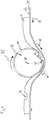
- FIG. 3 It is shown how initially the template 32 is applied to the laminate 10, which is indicated schematically by the arrow with the reference numeral 42.
- the work surface 30 is designed as the top of a conveyor belt 64.
- the conveyor belt 64 moves the laminate 10 along a transport direction 66.
- the transport direction 66 is in FIG. 3 symbolically represented by arrows with corresponding reference numerals.
- the template 32 is in the embodiment of FIG. 3 formed by a plurality of mutually unconnected stencil sections 68.
- the individual stencil sections 68 are applied to the laminate 10 in a desired arrangement relative to one another so that they respectively contact the second outer side 28 of the laminate 10 with its contact side 34.
- the conveyor belt 64 moves the laminate 10 with the stencil sections 68 lying thereon along the transport direction 66.
- a magnet 70 is arranged below the working surface 30.
- the magnet 70 is presently designed as an electromagnet 72.
- the electromagnet 72 When the electromagnet 72 is energized, it magnetically draws the stencil sections 68, which comprise a ferromagnetic material, against the working surface 30.
- the porous layer 12 of the laminate 10 is compressed in its extent from the working surface to the second outer side 28.
- the magnetic force of the electromagnet 72 is preferably as in FIG. 3 illustrated, adjusted such that the wound contact layer 14 is substantially not compressed.
- the porous layer 12 is compressed less than below the stencil sections 68.
- the parts 46 of the laminate 10 projecting over the upper side 36 of the stencil sections 68 are deflected by the movement of the conveyor belt 64 against a separator 48, which in the present case is a stationary blade. guided.
- a separator 48 which in the present case is a stationary blade. guided.
- the over the top 36 of the template parts 68 protruding parts of the laminate 10 are separated.
- the laminate 10 expands again to its original extent and it can be seen that at the locations where the parts 46 of the laminate detached were laminate 10 now has a recess or depression 76.
- FIG. 4 shows a further alternative for carrying out the method according to the invention.
- the laminate 10 is placed on a flexible conveyor belt 64.
- the top of the conveyor belt 64 simultaneously forms the work surface 30.
- the template 32 is designed as a roller which rotates about a rotation axis 80.
- the template 32 has a plurality of openings 38.
- a separator 48 is arranged, which is designed as a fixed blade.
- the parts of the laminate 10 or its porous layer 12, which are arranged below the apertures 38, extend through the openings 38 through the pressure of the elastic conveyor belt 64 and are separated by the separating device 48.
- the laminate 10 receives depressions or recesses 76 when the respective section of the laminate has passed the rotating template 32.
- step iv) Pressing the template according to step iv) is carried out by the elastic compliance of the conveyor belt 64.
- the template 32 in the example of FIG. 4 is fixed and relentless. However, it is also conceivable to use a rigid conveyor belt 64 and a resilient template 32.
- the pressing of the stencils in the direction of the working surface means pressurization of the laminate between stencil 32 and working surface 30.
- the template 32 can be moved toward the work surface and / or the work surface 30 can be moved toward the template 32.
- the laminate 10 preferably exclusively its porous layer 12
- a pressing also means pressurizing the laminate 10 by the template 32, in which the laminate 10 is not compressed, but is fixed only in its position on the work surface 30.
- To be separated parts 46 may in this case, for example.
- Fig.2 shown by elevations in the work surface over the top 36 of the template 32 are urged.
- FIG. 5a an exemplary contouring of a laminate 10 is shown.
- the laminate 10 has transverse and longitudinal recesses 84.
- the depressions 84 extend through the porous layer 12 and have been introduced into the porous layer 12 of the laminate 10 in a step v).
- a step vi) the laminate 10 in the example of FIG. 5a along the recesses 84 are completely divided by an essentially perpendicular to the extension plane 60 of the laminate 10 extending division process according to a step vi) into individual wound dressings 62.
- a wound dressing 62 can also have depressions 84 over its areal extent.
- the wound dressing 62 has chamfered edges 89 or side surfaces 89.
- FIG. 5c is shown on the wound dressing 62 off FIG. 5b a backing layer 90 can be applied.
- the backing layer 90 has an adhesive coating 88.
- the backing layer 90 is in the example of FIG. 5c formed as a polyurethane film and applied to the second outer side 28 of the wound dressing 86 and the laminate 10.
- the backing layer 90 may also project beyond the entire planar extent of the laminate 10, at least in regions, such that the wound dressing 62 has an adhesive edge 92.
- a wound dressing 62 with backing sheet 90, which forms an adhesive edge 92, is in FIG. 5d illustrated.
Landscapes
- Health & Medical Sciences (AREA)
- Engineering & Computer Science (AREA)
- Life Sciences & Earth Sciences (AREA)
- Animal Behavior & Ethology (AREA)
- Veterinary Medicine (AREA)
- Public Health (AREA)
- General Health & Medical Sciences (AREA)
- Manufacturing & Machinery (AREA)
- Vascular Medicine (AREA)
- Heart & Thoracic Surgery (AREA)
- Biomedical Technology (AREA)
- Chemical & Material Sciences (AREA)
- Mechanical Engineering (AREA)
- Forests & Forestry (AREA)
- Dispersion Chemistry (AREA)
- Hematology (AREA)
- Materials Engineering (AREA)
- Epidemiology (AREA)
- Materials For Medical Uses (AREA)
Applications Claiming Priority (1)
| Application Number | Priority Date | Filing Date | Title |
|---|---|---|---|
| DE102017131013.4A DE102017131013A1 (de) | 2017-12-21 | 2017-12-21 | Verfahren zur Herstellung einer Wundauflage |
Publications (2)
| Publication Number | Publication Date |
|---|---|
| EP3501465A1 true EP3501465A1 (fr) | 2019-06-26 |
| EP3501465B1 EP3501465B1 (fr) | 2023-07-26 |
Family
ID=64745948
Family Applications (1)
| Application Number | Title | Priority Date | Filing Date |
|---|---|---|---|
| EP18213647.3A Active EP3501465B1 (fr) | 2017-12-21 | 2018-12-18 | Procédé de fabrication d'un pansement |
Country Status (3)
| Country | Link |
|---|---|
| EP (1) | EP3501465B1 (fr) |
| DE (1) | DE102017131013A1 (fr) |
| PL (1) | PL3501465T3 (fr) |
Citations (6)
| Publication number | Priority date | Publication date | Assignee | Title |
|---|---|---|---|---|
| US5133821A (en) * | 1990-11-19 | 1992-07-28 | Jensen Ole R | Method for contouring hydrocolloid wound dressings |
| US6309500B1 (en) * | 1998-11-02 | 2001-10-30 | Robert Jensen | Method for manufacturing contoured and laminated materials |
| US20030120229A1 (en) * | 2001-12-21 | 2003-06-26 | De Jong Johannes H.A. | Process for the manufacture of multilayered wound dressings |
| DE10212866A1 (de) * | 2002-03-22 | 2003-10-09 | Beiersdorf Ag | Narbenreduktionspflaster |
| EP2158924A1 (fr) * | 2008-08-27 | 2010-03-03 | Bayer MaterialScience AG | Procédé de fabrication de pansements en mousse de polyuréthane formée |
| WO2013009239A1 (fr) * | 2011-07-08 | 2013-01-17 | Mölnlycke Health Care Ab | Produit auto-adhésif pour soin des plaies |
Family Cites Families (12)
| Publication number | Priority date | Publication date | Assignee | Title |
|---|---|---|---|---|
| US4935087A (en) * | 1987-12-14 | 1990-06-19 | The Kendall Company | Method of making an absorbent dressing |
| GB8917788D0 (en) | 1989-08-03 | 1989-09-20 | Smith & Nephew | Adhesive dressing |
| GB0027674D0 (en) | 2000-11-13 | 2000-12-27 | Johnson & Johnson Medical Ltd | Hydrogel wound dressings |
| US6904315B2 (en) | 2000-12-14 | 2005-06-07 | Medtronic, Inc. | Atrial aware VVI: a method for atrial synchronous ventricular (VDD/R) pacing using the subcutaneous electrode array and a standard pacing lead |
| GB2377939B (en) | 2001-07-26 | 2005-04-20 | Johnson & Johnson Medical Ltd | Apertured sheet materials |
| GB2387331B (en) | 2002-04-12 | 2005-03-23 | Johnson & Johnson Medical Ltd | Apertured hydrogel sheets |
| GB0229087D0 (en) | 2002-12-12 | 2003-01-15 | First Water Ltd | Absorbent hydrogel compositions |
| GB0425799D0 (en) | 2004-11-23 | 2004-12-22 | First Water Ltd | Absorbent hydrogel composites |
| AU2006294209A1 (en) | 2005-09-26 | 2007-03-29 | Coloplast A/S | Bevelled foam |
| DE102008031182A1 (de) | 2008-07-03 | 2010-01-07 | Paul Hartmann Ag | Wundauflage mit Hydrogelmatrix |
| US8302323B2 (en) * | 2010-06-21 | 2012-11-06 | Confluent Surgical, Inc. | Hemostatic patch |
| EP2532326B1 (fr) | 2011-06-09 | 2016-03-30 | Paul Hartmann AG | Pansement comprenant une étoffe nappée et une base de pommade destinées au traitement par dépressurisation |
-
2017
- 2017-12-21 DE DE102017131013.4A patent/DE102017131013A1/de not_active Withdrawn
-
2018
- 2018-12-18 EP EP18213647.3A patent/EP3501465B1/fr active Active
- 2018-12-18 PL PL18213647.3T patent/PL3501465T3/pl unknown
Patent Citations (6)
| Publication number | Priority date | Publication date | Assignee | Title |
|---|---|---|---|---|
| US5133821A (en) * | 1990-11-19 | 1992-07-28 | Jensen Ole R | Method for contouring hydrocolloid wound dressings |
| US6309500B1 (en) * | 1998-11-02 | 2001-10-30 | Robert Jensen | Method for manufacturing contoured and laminated materials |
| US20030120229A1 (en) * | 2001-12-21 | 2003-06-26 | De Jong Johannes H.A. | Process for the manufacture of multilayered wound dressings |
| DE10212866A1 (de) * | 2002-03-22 | 2003-10-09 | Beiersdorf Ag | Narbenreduktionspflaster |
| EP2158924A1 (fr) * | 2008-08-27 | 2010-03-03 | Bayer MaterialScience AG | Procédé de fabrication de pansements en mousse de polyuréthane formée |
| WO2013009239A1 (fr) * | 2011-07-08 | 2013-01-17 | Mölnlycke Health Care Ab | Produit auto-adhésif pour soin des plaies |
Also Published As
| Publication number | Publication date |
|---|---|
| PL3501465T3 (pl) | 2024-01-03 |
| DE102017131013A1 (de) | 2019-06-27 |
| EP3501465B1 (fr) | 2023-07-26 |
Similar Documents
| Publication | Publication Date | Title |
|---|---|---|
| DE69117497T2 (de) | Durch hydrieren aktivierbare bio-elektrode für iontophorese und verfahren zu ihrer herstellung | |
| EP3115033B1 (fr) | Pansement et son procédé de fabrication | |
| DE102009019646B4 (de) | Wundabdeckung und Verfahren zum Herstellen | |
| EP3139877B2 (fr) | Pansement en mousse pour traitement sous vide | |
| DE69009052T2 (de) | Absorbierende körper sowie deren vorstufen. | |
| DE102008062472A1 (de) | Wundverband für die Unterdrucktherapie | |
| WO2010000450A2 (fr) | Pansement à matrice d'hydrogel | |
| EP2909013A1 (fr) | Dispositif et procédé de fabrication d'une semelle de longeron de pale de rotor | |
| EP2635244A1 (fr) | Pansement pour plaie comprenant une couche de biocellulose et équipé pour adsorber des bactéries | |
| EP2934409A1 (fr) | Corps d'aspiration pour le traitement thérapeutique d'une plaie par dépression | |
| DE60215347T2 (de) | Wundverband | |
| EP3501466B1 (fr) | Procédé de traitement d'un substrat | |
| DE102006031418B4 (de) | Okklusiv- oder Semiokklusivverband zur Auflage an menschliche oder tierische Wundflächen und dessen Verwendung | |
| EP3043985A1 (fr) | Procédé et dispositif permettant de rogner un demi-produit préfabriqué | |
| EP3501465B1 (fr) | Procédé de fabrication d'un pansement | |
| DE102013002497A1 (de) | Verbandset zur Behandlung von Wundkavitäten | |
| DE10012582C2 (de) | Verfahren zum Herstellen eines Verbandmaterials und Verbandmaterial | |
| DE102022133930A1 (de) | Wundverband zur Verwendung in der Unterdrucktherapie von Wunden, Unterdruck-Wundtherapiekit und Unterdruck-Wundtherapiesystem | |
| DD252950A3 (de) | Medizinischer wundverband | |
| DE102011050047A1 (de) | Wundpflegeartikel für Kavitäten | |
| DE886072C (de) | Verfahren zur Herstellung von dicken, luftdurchlaessigen Schichten aus Gewebe und Kautschuk mit offenen oder geschlossenen Zellen | |
| DE20103311U1 (de) | Wundauflage | |
| DE102023106503A1 (de) | Dichtband mit Faserschicht |
Legal Events
| Date | Code | Title | Description |
|---|---|---|---|
| PUAI | Public reference made under article 153(3) epc to a published international application that has entered the european phase |
Free format text: ORIGINAL CODE: 0009012 |
|
| STAA | Information on the status of an ep patent application or granted ep patent |
Free format text: STATUS: THE APPLICATION HAS BEEN PUBLISHED |
|
| AK | Designated contracting states |
Kind code of ref document: A1 Designated state(s): AL AT BE BG CH CY CZ DE DK EE ES FI FR GB GR HR HU IE IS IT LI LT LU LV MC MK MT NL NO PL PT RO RS SE SI SK SM TR |
|
| AX | Request for extension of the european patent |
Extension state: BA ME |
|
| STAA | Information on the status of an ep patent application or granted ep patent |
Free format text: STATUS: REQUEST FOR EXAMINATION WAS MADE |
|
| 17P | Request for examination filed |
Effective date: 20191204 |
|
| RBV | Designated contracting states (corrected) |
Designated state(s): AL AT BE BG CH CY CZ DE DK EE ES FI FR GB GR HR HU IE IS IT LI LT LU LV MC MK MT NL NO PL PT RO RS SE SI SK SM TR |
|
| STAA | Information on the status of an ep patent application or granted ep patent |
Free format text: STATUS: EXAMINATION IS IN PROGRESS |
|
| 17Q | First examination report despatched |
Effective date: 20220302 |
|
| GRAP | Despatch of communication of intention to grant a patent |
Free format text: ORIGINAL CODE: EPIDOSNIGR1 |
|
| STAA | Information on the status of an ep patent application or granted ep patent |
Free format text: STATUS: GRANT OF PATENT IS INTENDED |
|
| INTG | Intention to grant announced |
Effective date: 20230222 |
|
| GRAS | Grant fee paid |
Free format text: ORIGINAL CODE: EPIDOSNIGR3 |
|
| GRAA | (expected) grant |
Free format text: ORIGINAL CODE: 0009210 |
|
| STAA | Information on the status of an ep patent application or granted ep patent |
Free format text: STATUS: THE PATENT HAS BEEN GRANTED |
|
| P01 | Opt-out of the competence of the unified patent court (upc) registered |
Effective date: 20230519 |
|
| AK | Designated contracting states |
Kind code of ref document: B1 Designated state(s): AL AT BE BG CH CY CZ DE DK EE ES FI FR GB GR HR HU IE IS IT LI LT LU LV MC MK MT NL NO PL PT RO RS SE SI SK SM TR |
|
| REG | Reference to a national code |
Ref country code: CH Ref legal event code: EP |
|
| REG | Reference to a national code |
Ref country code: DE Ref legal event code: R096 Ref document number: 502018012778 Country of ref document: DE |
|
| REG | Reference to a national code |
Ref country code: IE Ref legal event code: FG4D Free format text: LANGUAGE OF EP DOCUMENT: GERMAN |
|
| REG | Reference to a national code |
Ref country code: LT Ref legal event code: MG9D |
|
| REG | Reference to a national code |
Ref country code: NL Ref legal event code: MP Effective date: 20230726 |
|
| PG25 | Lapsed in a contracting state [announced via postgrant information from national office to epo] |
Ref country code: NL Free format text: LAPSE BECAUSE OF FAILURE TO SUBMIT A TRANSLATION OF THE DESCRIPTION OR TO PAY THE FEE WITHIN THE PRESCRIBED TIME-LIMIT Effective date: 20230726 |
|
| PG25 | Lapsed in a contracting state [announced via postgrant information from national office to epo] |
Ref country code: GR Free format text: LAPSE BECAUSE OF FAILURE TO SUBMIT A TRANSLATION OF THE DESCRIPTION OR TO PAY THE FEE WITHIN THE PRESCRIBED TIME-LIMIT Effective date: 20231027 |
|
| PG25 | Lapsed in a contracting state [announced via postgrant information from national office to epo] |
Ref country code: IS Free format text: LAPSE BECAUSE OF FAILURE TO SUBMIT A TRANSLATION OF THE DESCRIPTION OR TO PAY THE FEE WITHIN THE PRESCRIBED TIME-LIMIT Effective date: 20231126 |
|
| PG25 | Lapsed in a contracting state [announced via postgrant information from national office to epo] |
Ref country code: SE Free format text: LAPSE BECAUSE OF FAILURE TO SUBMIT A TRANSLATION OF THE DESCRIPTION OR TO PAY THE FEE WITHIN THE PRESCRIBED TIME-LIMIT Effective date: 20230726 Ref country code: RS Free format text: LAPSE BECAUSE OF FAILURE TO SUBMIT A TRANSLATION OF THE DESCRIPTION OR TO PAY THE FEE WITHIN THE PRESCRIBED TIME-LIMIT Effective date: 20230726 Ref country code: PT Free format text: LAPSE BECAUSE OF FAILURE TO SUBMIT A TRANSLATION OF THE DESCRIPTION OR TO PAY THE FEE WITHIN THE PRESCRIBED TIME-LIMIT Effective date: 20231127 Ref country code: NO Free format text: LAPSE BECAUSE OF FAILURE TO SUBMIT A TRANSLATION OF THE DESCRIPTION OR TO PAY THE FEE WITHIN THE PRESCRIBED TIME-LIMIT Effective date: 20231026 Ref country code: LV Free format text: LAPSE BECAUSE OF FAILURE TO SUBMIT A TRANSLATION OF THE DESCRIPTION OR TO PAY THE FEE WITHIN THE PRESCRIBED TIME-LIMIT Effective date: 20230726 Ref country code: LT Free format text: LAPSE BECAUSE OF FAILURE TO SUBMIT A TRANSLATION OF THE DESCRIPTION OR TO PAY THE FEE WITHIN THE PRESCRIBED TIME-LIMIT Effective date: 20230726 Ref country code: IS Free format text: LAPSE BECAUSE OF FAILURE TO SUBMIT A TRANSLATION OF THE DESCRIPTION OR TO PAY THE FEE WITHIN THE PRESCRIBED TIME-LIMIT Effective date: 20231126 Ref country code: HR Free format text: LAPSE BECAUSE OF FAILURE TO SUBMIT A TRANSLATION OF THE DESCRIPTION OR TO PAY THE FEE WITHIN THE PRESCRIBED TIME-LIMIT Effective date: 20230726 Ref country code: GR Free format text: LAPSE BECAUSE OF FAILURE TO SUBMIT A TRANSLATION OF THE DESCRIPTION OR TO PAY THE FEE WITHIN THE PRESCRIBED TIME-LIMIT Effective date: 20231027 Ref country code: FI Free format text: LAPSE BECAUSE OF FAILURE TO SUBMIT A TRANSLATION OF THE DESCRIPTION OR TO PAY THE FEE WITHIN THE PRESCRIBED TIME-LIMIT Effective date: 20230726 |
|
| PG25 | Lapsed in a contracting state [announced via postgrant information from national office to epo] |
Ref country code: ES Free format text: LAPSE BECAUSE OF FAILURE TO SUBMIT A TRANSLATION OF THE DESCRIPTION OR TO PAY THE FEE WITHIN THE PRESCRIBED TIME-LIMIT Effective date: 20230726 |
|
| REG | Reference to a national code |
Ref country code: DE Ref legal event code: R097 Ref document number: 502018012778 Country of ref document: DE |
|
| PG25 | Lapsed in a contracting state [announced via postgrant information from national office to epo] |
Ref country code: SM Free format text: LAPSE BECAUSE OF FAILURE TO SUBMIT A TRANSLATION OF THE DESCRIPTION OR TO PAY THE FEE WITHIN THE PRESCRIBED TIME-LIMIT Effective date: 20230726 Ref country code: RO Free format text: LAPSE BECAUSE OF FAILURE TO SUBMIT A TRANSLATION OF THE DESCRIPTION OR TO PAY THE FEE WITHIN THE PRESCRIBED TIME-LIMIT Effective date: 20230726 Ref country code: ES Free format text: LAPSE BECAUSE OF FAILURE TO SUBMIT A TRANSLATION OF THE DESCRIPTION OR TO PAY THE FEE WITHIN THE PRESCRIBED TIME-LIMIT Effective date: 20230726 Ref country code: EE Free format text: LAPSE BECAUSE OF FAILURE TO SUBMIT A TRANSLATION OF THE DESCRIPTION OR TO PAY THE FEE WITHIN THE PRESCRIBED TIME-LIMIT Effective date: 20230726 Ref country code: DK Free format text: LAPSE BECAUSE OF FAILURE TO SUBMIT A TRANSLATION OF THE DESCRIPTION OR TO PAY THE FEE WITHIN THE PRESCRIBED TIME-LIMIT Effective date: 20230726 Ref country code: CZ Free format text: LAPSE BECAUSE OF FAILURE TO SUBMIT A TRANSLATION OF THE DESCRIPTION OR TO PAY THE FEE WITHIN THE PRESCRIBED TIME-LIMIT Effective date: 20230726 Ref country code: SK Free format text: LAPSE BECAUSE OF FAILURE TO SUBMIT A TRANSLATION OF THE DESCRIPTION OR TO PAY THE FEE WITHIN THE PRESCRIBED TIME-LIMIT Effective date: 20230726 |
|
| PLBE | No opposition filed within time limit |
Free format text: ORIGINAL CODE: 0009261 |
|
| STAA | Information on the status of an ep patent application or granted ep patent |
Free format text: STATUS: NO OPPOSITION FILED WITHIN TIME LIMIT |
|
| 26N | No opposition filed |
Effective date: 20240429 |
|
| PG25 | Lapsed in a contracting state [announced via postgrant information from national office to epo] |
Ref country code: SI Free format text: LAPSE BECAUSE OF FAILURE TO SUBMIT A TRANSLATION OF THE DESCRIPTION OR TO PAY THE FEE WITHIN THE PRESCRIBED TIME-LIMIT Effective date: 20230726 |
|
| REG | Reference to a national code |
Ref country code: CH Ref legal event code: PL |
|
| PG25 | Lapsed in a contracting state [announced via postgrant information from national office to epo] |
Ref country code: LU Free format text: LAPSE BECAUSE OF NON-PAYMENT OF DUE FEES Effective date: 20231218 |
|
| PG25 | Lapsed in a contracting state [announced via postgrant information from national office to epo] |
Ref country code: MC Free format text: LAPSE BECAUSE OF FAILURE TO SUBMIT A TRANSLATION OF THE DESCRIPTION OR TO PAY THE FEE WITHIN THE PRESCRIBED TIME-LIMIT Effective date: 20230726 |
|
| REG | Reference to a national code |
Ref country code: BE Ref legal event code: MM Effective date: 20231231 |
|
| PG25 | Lapsed in a contracting state [announced via postgrant information from national office to epo] |
Ref country code: MC Free format text: LAPSE BECAUSE OF FAILURE TO SUBMIT A TRANSLATION OF THE DESCRIPTION OR TO PAY THE FEE WITHIN THE PRESCRIBED TIME-LIMIT Effective date: 20230726 Ref country code: LU Free format text: LAPSE BECAUSE OF NON-PAYMENT OF DUE FEES Effective date: 20231218 |
|
| REG | Reference to a national code |
Ref country code: IE Ref legal event code: MM4A |
|
| PG25 | Lapsed in a contracting state [announced via postgrant information from national office to epo] |
Ref country code: IE Free format text: LAPSE BECAUSE OF NON-PAYMENT OF DUE FEES Effective date: 20231218 |
|
| PG25 | Lapsed in a contracting state [announced via postgrant information from national office to epo] |
Ref country code: BE Free format text: LAPSE BECAUSE OF NON-PAYMENT OF DUE FEES Effective date: 20231231 |
|
| PG25 | Lapsed in a contracting state [announced via postgrant information from national office to epo] |
Ref country code: CH Free format text: LAPSE BECAUSE OF NON-PAYMENT OF DUE FEES Effective date: 20231231 |
|
| PG25 | Lapsed in a contracting state [announced via postgrant information from national office to epo] |
Ref country code: IE Free format text: LAPSE BECAUSE OF NON-PAYMENT OF DUE FEES Effective date: 20231218 Ref country code: CH Free format text: LAPSE BECAUSE OF NON-PAYMENT OF DUE FEES Effective date: 20231231 Ref country code: BE Free format text: LAPSE BECAUSE OF NON-PAYMENT OF DUE FEES Effective date: 20231231 |
|
| PG25 | Lapsed in a contracting state [announced via postgrant information from national office to epo] |
Ref country code: BG Free format text: LAPSE BECAUSE OF FAILURE TO SUBMIT A TRANSLATION OF THE DESCRIPTION OR TO PAY THE FEE WITHIN THE PRESCRIBED TIME-LIMIT Effective date: 20230726 |
|
| PG25 | Lapsed in a contracting state [announced via postgrant information from national office to epo] |
Ref country code: BG Free format text: LAPSE BECAUSE OF FAILURE TO SUBMIT A TRANSLATION OF THE DESCRIPTION OR TO PAY THE FEE WITHIN THE PRESCRIBED TIME-LIMIT Effective date: 20230726 |
|
| REG | Reference to a national code |
Ref country code: AT Ref legal event code: MM01 Ref document number: 1591098 Country of ref document: AT Kind code of ref document: T Effective date: 20231218 |
|
| PG25 | Lapsed in a contracting state [announced via postgrant information from national office to epo] |
Ref country code: AT Free format text: LAPSE BECAUSE OF NON-PAYMENT OF DUE FEES Effective date: 20231218 |
|
| PG25 | Lapsed in a contracting state [announced via postgrant information from national office to epo] |
Ref country code: CY Free format text: LAPSE BECAUSE OF FAILURE TO SUBMIT A TRANSLATION OF THE DESCRIPTION OR TO PAY THE FEE WITHIN THE PRESCRIBED TIME-LIMIT; INVALID AB INITIO Effective date: 20181218 |
|
| PG25 | Lapsed in a contracting state [announced via postgrant information from national office to epo] |
Ref country code: HU Free format text: LAPSE BECAUSE OF FAILURE TO SUBMIT A TRANSLATION OF THE DESCRIPTION OR TO PAY THE FEE WITHIN THE PRESCRIBED TIME-LIMIT; INVALID AB INITIO Effective date: 20181218 |
|
| PG25 | Lapsed in a contracting state [announced via postgrant information from national office to epo] |
Ref country code: TR Free format text: LAPSE BECAUSE OF FAILURE TO SUBMIT A TRANSLATION OF THE DESCRIPTION OR TO PAY THE FEE WITHIN THE PRESCRIBED TIME-LIMIT Effective date: 20230726 |
|
| PGFP | Annual fee paid to national office [announced via postgrant information from national office to epo] |
Ref country code: GB Payment date: 20251218 Year of fee payment: 8 |
|
| PGFP | Annual fee paid to national office [announced via postgrant information from national office to epo] |
Ref country code: FR Payment date: 20251218 Year of fee payment: 8 |
|
| PGFP | Annual fee paid to national office [announced via postgrant information from national office to epo] |
Ref country code: PL Payment date: 20251211 Year of fee payment: 8 |
|
| PGFP | Annual fee paid to national office [announced via postgrant information from national office to epo] |
Ref country code: DE Payment date: 20251222 Year of fee payment: 8 |
|
| PGFP | Annual fee paid to national office [announced via postgrant information from national office to epo] |
Ref country code: IT Payment date: 20251231 Year of fee payment: 8 |