EP3501663B1 - Ensemble de rondelle d'écoulement - Google Patents
Ensemble de rondelle d'écoulement Download PDFInfo
- Publication number
- EP3501663B1 EP3501663B1 EP18207864.2A EP18207864A EP3501663B1 EP 3501663 B1 EP3501663 B1 EP 3501663B1 EP 18207864 A EP18207864 A EP 18207864A EP 3501663 B1 EP3501663 B1 EP 3501663B1
- Authority
- EP
- European Patent Office
- Prior art keywords
- washer
- channel
- flow
- seat
- retainer
- Prior art date
- Legal status (The legal status is an assumption and is not a legal conclusion. Google has not performed a legal analysis and makes no representation as to the accuracy of the status listed.)
- Active
Links
Images


Classifications
-
- G—PHYSICS
- G05—CONTROLLING; REGULATING
- G05D—SYSTEMS FOR CONTROLLING OR REGULATING NON-ELECTRIC VARIABLES
- G05D7/00—Control of flow
- G05D7/01—Control of flow without auxiliary power
- G05D7/0106—Control of flow without auxiliary power the sensing element being a flexible member, e.g. bellows, diaphragm, capsule
- G05D7/012—Control of flow without auxiliary power the sensing element being a flexible member, e.g. bellows, diaphragm, capsule the sensing element being deformable and acting as a valve
-
- B—PERFORMING OPERATIONS; TRANSPORTING
- B05—SPRAYING OR ATOMISING IN GENERAL; APPLYING FLUENT MATERIALS TO SURFACES, IN GENERAL
- B05B—SPRAYING APPARATUS; ATOMISING APPARATUS; NOZZLES
- B05B1/00—Nozzles, spray heads or other outlets, with or without auxiliary devices such as valves, heating means
- B05B1/30—Nozzles, spray heads or other outlets, with or without auxiliary devices such as valves, heating means designed to control volume of flow, e.g. with adjustable passages
- B05B1/3006—Nozzles, spray heads or other outlets, with or without auxiliary devices such as valves, heating means designed to control volume of flow, e.g. with adjustable passages the controlling element being actuated by the pressure of the fluid to be sprayed
-
- B—PERFORMING OPERATIONS; TRANSPORTING
- B05—SPRAYING OR ATOMISING IN GENERAL; APPLYING FLUENT MATERIALS TO SURFACES, IN GENERAL
- B05B—SPRAYING APPARATUS; ATOMISING APPARATUS; NOZZLES
- B05B1/00—Nozzles, spray heads or other outlets, with or without auxiliary devices such as valves, heating means
- B05B1/30—Nozzles, spray heads or other outlets, with or without auxiliary devices such as valves, heating means designed to control volume of flow, e.g. with adjustable passages
- B05B1/32—Nozzles, spray heads or other outlets, with or without auxiliary devices such as valves, heating means designed to control volume of flow, e.g. with adjustable passages in which a valve member forms part of the outlet opening
- B05B1/323—Nozzles, spray heads or other outlets, with or without auxiliary devices such as valves, heating means designed to control volume of flow, e.g. with adjustable passages in which a valve member forms part of the outlet opening the valve member being actuated by the pressure of the fluid to be sprayed
-
- F—MECHANICAL ENGINEERING; LIGHTING; HEATING; WEAPONS; BLASTING
- F16—ENGINEERING ELEMENTS AND UNITS; GENERAL MEASURES FOR PRODUCING AND MAINTAINING EFFECTIVE FUNCTIONING OF MACHINES OR INSTALLATIONS; THERMAL INSULATION IN GENERAL
- F16K—VALVES; TAPS; COCKS; ACTUATING-FLOATS; DEVICES FOR VENTING OR AERATING
- F16K27/00—Construction of housing; Use of materials therefor
- F16K27/02—Construction of housing; Use of materials therefor of lift valves
- F16K27/0254—Construction of housing; Use of materials therefor of lift valves with conical shaped valve members
Definitions
- the invention relates to a flow washer assembly and, more particularly, to a flow washer assembly that regulates flow of fluid with a dynamically changing orifice diameter to keep the flow rate of fluid constant within a given pressure range.
- the assembly endeavors to eliminate a spike in flow rate that occurs with conventional flow washer assemblies.
- a common problem with this type of flow control device is a "spike" in the flow rate as the inlet pressure is increased from zero psi to the operating range. As the inlet pressure increases, so does the flow rate through the device, until such time as the inlet pressure is great enough to cause a deflection of the elastomeric washer, which in turn causes a reduction in washer orifice diameter, resulting in a flow rate reduction.
- the flow spike occurs at the point where the pressure is great enough to cause an "overflow” or “spike” condition yet not great enough to cause a deflection in the elastomeric washer.
- US 2,454,929 discloses a flow control device.
- this "spike” in the flow rate can create a significant problem.
- the water pump that pressurizes the system is usually sized so that it supplies just enough water flow to pressurize a given number of sprinklers at a certain maximum flow rate.
- the water pump cannot produce enough flow to adequately pressurize the system.
- the flow control devices at each individual sprinkler will never get enough pressure to regulate the flow rate. As a consequence, the system will never get to its optimal operating pressure, and the individual sprinklers will not function as designed.
- the flow washer assembly of claim 1 and the method of installing a flow washer assembly of claim 9. Additional aspects of the invention are set out in the dependent claims.
- Exemplary embodiments according to the present disclosure incorporate features that may contribute to eliminating the flow "spike” condition.
- the flow washer may include an outside diameter ring that is cooperable with the housing to "pre-flex” the washer, which will eliminate the flow "spike” condition.
- the washer may include pre-load protrusions or bumps that interact with a retainer washer to effect pre-flexing of the washer.
- a seat adjacent to which the flow washer is placed may include an upstream surface that facilitates pre-flexing of the washer.
- a flow washer assembly including a housing with a channel for fluid flow, a seat positioned in the channel and including an upstream surface, and a washer that is press fit into the channel and engaging the upstream surface of the seat.
- the washer is provided with a central opening that is sized according to predefined flow characteristics.
- An outside diameter of the washer that is at least adjacent to an upstream end is greater than an inside diameter of the channel such that the washer assumes a flexed orientation when it is press fit into the channel.
- the outside diameter of the washer may be tapered across its thickness from a maximum diameter at the upstream end to a minimum diameter at a downstream end such that the washer may be part-conical shaped.
- the upstream surface may be shaped to receive the washer in the flexed orientation.
- the upstream surface of the seat may be concave.
- the channel may include a shoulder, and the seat may be press fit in the channel adjacent to the shoulder.
- a retainer may be positioned in the channel and may be engaged with the washer, where the washer may be sandwiched between the seat and the retainer.
- the washer may include a plurality of protrusions on a side thereof facing the retainer, where the retainer may be positioned in engagement with the protrusions to deflect the washer toward the flexed orientation.
- the protrusions are disposed inside a perimeter of the washer surrounding the central opening.
- a flow washer assembly including a housing with a channel for fluid flow, a seat positioned in the channel and including an upstream surface, a washer press fit in the channel and engaging the upstream surface of the seat on a downstream side, and a retainer positioned in the channel and engaging the washer such that the washer is sandwiched between the seat and the retainer.
- the washer may include a plurality of protrusions on an upstream side and a central opening that is sized according to predefined flow characteristics.
- the retainer may be positioned in engagement with the protrusions to deflect the washer toward a flexed orientation.
- An outside diameter of the washer that is at least adjacent to an upstream end is greater than an inside diameter of the channel such that the washer assumes the flexed orientation when press fit into the channel.
- the outside diameter of the washer may be tapered across its thickness from a maximum diameter at the upstream end to a minimum diameter at a downstream end such that the washer is part-conical shaped.
- the upstream surface may be shaped to receive the washer in the flexed orientation.
- the upstream surface of the seat may be concave.
- the channel may comprise a shoulder, and the seat may be press fit in the channel adjacent the shoulder.
- a method of installing a washer assembly into a housing with a channel for fluid flow which method includes the steps of positioning a seat in the channel, the seat having an upstream surface; and press fitting the washer in the channel until the washer assumes a flexed orientation in engagement with the upstream surface of the seat.
- the method may further comprise positioning a retainer in the channel into engagement with the washer such that the washer is sandwiched between the seat and the retainer.
- the washer may comprise a plurality of protrusions on a side thereof facing the retainer, and the positioning step may comprise positioning the retainer in engagement with the protrusions to deflect the washer toward the flexed orientation.
- the upstream surface of the seat may be concave, and the method may further comprise deflecting the washer into the concave upstream surface of the seat.
- a flow washer including a plurality of protrusions on an upstream side and a central opening that is sized according to predefined flow characteristics.
- An outside diameter of the washer that is at least adjacent to an upstream end may be greater than the outside diameter adjacent to a downstream end.
- the outside diameter of the washer may be tapered across its thickness from a maximum diameter at the upstream end to a minimum diameter at the downstream end such that the washer is part-conical shaped.
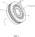
- FIG. 1 is a perspective view of a flow washer 12 forming part of the flow washer assembly 10 shown in FIG. 2 .
- the flow washer assembly 10 includes a housing 14 with a channel 16 for fluid flow.
- the housing 14 may include a shoulder 18 in the channel 16 for receiving a seat washer or seat 20.
- the seat 20 is press fit in the channel 16 adjacent the shoulder 18.
- the seat 20 includes a central opening 22 and an upstream surface 24.
- the upstream surface 24 may generally be concave as shown in FIG. 2 . That is, the upstream surface 24 may be provided with an overall concave configuration with tapered or curved sides or the like.
- the washer 12 is press fit in the channel 16 and engages at least the outermost portions of the upstream surface 24 of the seat 20.
- the washer 12 includes a central opening 26 that is sized according to predefined flow characteristics.
- the washer 12 may include an outside diameter section or ring 28 at least adjacent an upstream end of the washer 12 that is greater than an inside diameter of the channel 16.
- the outside diameter section or ring 28 of the washer 12 intersects the inside diameter of the channel 16.
- the washer 12 is preferably constructed of an elastomeric material, and the engagement of the outside diameter section or ring 28 with the inside diameter of the channel 16 effects a flexed orientation of the washer 12 in the channel 16.
- the washer 12 may additionally include a recess 29 adjacent the outside diameter section 28 that allows the ring to flex more readily during installation in the channel 16.
- the concave shape of the seat inside surface 24 also serves to facilitate the flexed orientation of the washer 12 in the channel 16.
- the outside diameter of the washer 12 may be tapered across its thickness t from a maximum diameter at the upstream end to a minimum diameter at the downstream end as shown by arrow A. As shown in FIG. 3 , the washer 12 may thus be part-conical shaped across its thickness t.
- the washer 12 may additionally be provided with a plurality of protrusions 30 on an upstream side of the washer 12.
- the protrusions 30 are generally disposed inside a perimeter of the washer 12 surrounding the central opening 26 as shown in FIG. 1 .
- the protrusions 30 are cooperable with a retainer washer or retainer 32 that may be positioned in the channel 16 and engaged with an upstream side of the washer 12. As shown in FIG. 2 , with the retainer 32 installed in the channel 16, the washer 12 is sandwiched between the seat 20 and the retainer 32. When installed, the retainer 32 engages the protrusions 30 on the washer 12 to deflect the washer 12 toward the flexed orientation.
- the flow washer assembly 10 may be assembled with the seat 20 and washer 12 without the retainer 32.
- the flow washer assembly may include the retainer 32 without the seat 20 or may include both the seat 20 and retainer 32 as shown in FIG. 2 .
- fluid flows through the flow washer assembly 10, and the flow of fluid is restricted by the orifice or central opening 26 of the washer 12.
- a diameter of the central opening 26 changes with inlet fluid pressure. That is, as the inlet fluid pressure increases, the diameter of the central opening 26 is reduced in size, which regulates the flow of fluid through the assembly 10. This dynamically changing orifice diameter does so in such a manner as to keep the flow rate of fluid through the device relatively constant within a given pressure range.
- the protrusions 30 also contribute to the pre-flexing of the washer 12 when used with the retainer 32.
- the washer 12 is sandwiched between the seat 20 and the retainer 32.
- the retainer 32 engages the protrusions 30 on the washer 12. This engagement causes a deflection of the washer 12, which further causes the inlet side of the washer 12 to become concave in shape.
- This concave shape translates to a reduction in the central opening 26 size even at zero inlet pressure.
- the reduced central opening 26 reduces the fluid flow through the device.
- the washer 12 Since the washer 12 is pre-deflected by the engagement between its outside diameter and the inside diameter of the channel 16 of the housing and/or by the retainer 32 engaging the protrusions 30 on the washer 12, the washer 12 continues to deflect further as inlet fluid pressure increases, effectively keeping the fluid flow rate relatively constant across a given pressure range.
- the mechanical "pre-flexing" of the washer eliminates the spike in flow rate through the device that occurs with existing assemblies.
- the seat is shaped in such a manner that it allows the washer to further deform when fluid pressure is applied to the inlet.
Landscapes
- Engineering & Computer Science (AREA)
- General Engineering & Computer Science (AREA)
- Physics & Mathematics (AREA)
- General Physics & Mathematics (AREA)
- Automation & Control Theory (AREA)
- Mechanical Engineering (AREA)
- Infusion, Injection, And Reservoir Apparatuses (AREA)
- Lift Valve (AREA)
- Pipe Accessories (AREA)
Claims (12)
- Ensemble de rondelle d'écoulement (10) comprenant :un boîtier (14) avec un canal (16) pour l'écoulement de fluide ;un siège (20) positionné dans le canal (16) et comprenant une surface amont (24) ; et caractérisé en ce que l'ensemble de rondelle d'écoulement comprend en outre :une rondelle (12) qui est ajustée à force dans le canal (16) et engageant la surface amont (24) du siège (20), la rondelle (12) comprenant une ouverture centrale (26) qui est dimensionné selon des caractéristiques d'écoulement prédéfinies,dans lequel un diamètre extérieur (28) de la rondelle (12) qui est au moins adjacent à une extrémité amont est supérieur à un diamètre intérieur du canal (16) de sorte que la rondelle (12) prend une orientation fléchie par engagement du diamètre extérieur (28) de la rondelle (12) avec le diamètre intérieur du canal (16) lorsque la rondelle est ajustée à force dans le canal (16).
- Ensemble de rondelle d'écoulement (10) selon la revendication 1, dans lequel le diamètre extérieur de la rondelle (12) est effilé sur son épaisseur depuis un diamètre maximal à l'extrémité amont jusqu'à un diamètre minimal à une extrémité aval de telle sorte que la rondelle (12) est de forme partiellement conique.
- Ensemble de rondelle d'écoulement (10) selon la revendication 1 ou 2, dans lequel la surface amont (24) est formée pour recevoir la rondelle (12) dans l'orientation fléchie.
- Ensemble de rondelle d'écoulement (10) selon la revendication 3, dans lequel la surface amont (24) du siège (20) est concave.
- Ensemble de rondelle d'écoulement (10) selon l'une quelconque des revendications précédentes, dans lequel le canal (16) comprend un épaulement (18), et dans lequel le siège (20) est ajusté à force dans le canal (16) adjacent à l'épaule (18).
- Ensemble de rondelle d'écoulement (10) selon l'une quelconque des revendications précédentes, comprenant en outre un élément de retenue (32) positionné dans le canal (16) et engageant la rondelle (12), dans lequel la rondelle (12) est prise en sandwich entre le siège (20) et l'élément de retenue (32).
- Ensemble de rondelle d'écoulement (10) selon la revendication 6, dans lequel la rondelle (12) comprend une pluralité de saillies (30) sur un côté de celle-ci faisant face à l'élément de retenue (32), dans lequel l'élément de retenue (32) est positionné en engagement avec les saillies (30) pour dévier la rondelle (12) vers l'orientation fléchie.
- Ensemble de rondelle d'écoulement (10) selon la revendication 7, dans lequel les saillies (30) sont disposées à l'intérieur d'un périmètre de la rondelle (12) entourant l'ouverture centrale (26).
- Procédé d'installation d'un ensemble de rondelle (12, 20, 32) dans un boîtier (14) avec un canal (16) pour l'écoulement d'un fluide, l'ensemble de rondelle (12, 20, 32) comprenant une rondelle (12) avec une ouverture centrale dimensionnée selon des caractéristiques d'écoulement prédéfinies, le procédé comprenant :le positionnement d'un siège (20) dans le canal (16), le siège (20) ayant une surface amont (24) ;et caractérisé par :l'ajustement à force de la rondelle (12) dans le canal (16) jusqu'à ce que la rondelle (12) prenne une orientation fléchie en engagement avec la surface amont (24) du siège (20),dans lequel un diamètre extérieur (28) de la rondelle (12) au moins adjacent à une extrémité amont est supérieur à un diamètre intérieur du canal (16).
- Procédé selon la revendication 9, comprenant en outre le positionnement d'un élément de retenue (32) dans le canal (16) en engagement avec la rondelle (12) de telle sorte que la rondelle (12) soit prise en sandwich entre le siège (20) et l'élément de retenue (32).
- Procédé selon la revendication 10, dans lequel la rondelle (12) comprend une pluralité de saillies (30) sur un côté de celle-ci faisant face au dispositif de retenue (32), et dans lequel l'étape de positionnement comprend le positionnement de l'élément de retenue (32) en engagement avec les saillies (30) pour dévier la rondelle (12) vers l'orientation fléchie.
- Procédé selon la revendication 9, 10 ou 11, dans lequel la surface amont (24) du siège (20) est concave, le procédé comprenant en outre la déviation de la rondelle (12) dans la surface amont concave (24) du siège (20).
Applications Claiming Priority (1)
| Application Number | Priority Date | Filing Date | Title |
|---|---|---|---|
| US15/846,439 US10401877B2 (en) | 2017-12-19 | 2017-12-19 | Flow washer assembly |
Publications (2)
| Publication Number | Publication Date |
|---|---|
| EP3501663A1 EP3501663A1 (fr) | 2019-06-26 |
| EP3501663B1 true EP3501663B1 (fr) | 2022-01-19 |
Family
ID=64453406
Family Applications (1)
| Application Number | Title | Priority Date | Filing Date |
|---|---|---|---|
| EP18207864.2A Active EP3501663B1 (fr) | 2017-12-19 | 2018-11-22 | Ensemble de rondelle d'écoulement |
Country Status (5)
| Country | Link |
|---|---|
| US (1) | US10401877B2 (fr) |
| EP (1) | EP3501663B1 (fr) |
| AU (1) | AU2018253650B2 (fr) |
| ES (1) | ES2906340T3 (fr) |
| IL (1) | IL262774B (fr) |
Families Citing this family (1)
| Publication number | Priority date | Publication date | Assignee | Title |
|---|---|---|---|---|
| CZ309816B6 (cs) * | 2022-06-03 | 2023-11-01 | Vysoké Učení Technické V Brně | Zařízení k regulaci průtoku média, zejména pro trysky |
Family Cites Families (22)
| Publication number | Priority date | Publication date | Assignee | Title |
|---|---|---|---|---|
| US2899979A (en) * | 1959-08-18 | Flow control device | ||
| US2454929A (en) * | 1944-07-17 | 1948-11-30 | Dole Valve Co | Flow control |
| US2728355A (en) * | 1953-10-30 | 1955-12-27 | Dole Valve Co | By-pass flow washer |
| US2936788A (en) * | 1955-04-26 | 1960-05-17 | Dole Valve Co | Flow control system |
| US2891578A (en) * | 1955-12-19 | 1959-06-23 | Dole Valve Co | Flow control device |
| US2936790A (en) * | 1955-12-27 | 1960-05-17 | Dole Valve Co | Noise reducing flow control device |
| US2939487A (en) | 1957-08-21 | 1960-06-07 | Speakman Co | Flow control device |
| US3138177A (en) * | 1961-09-06 | 1964-06-23 | Gen Electric | Flow control device |
| US3768507A (en) * | 1971-07-02 | 1973-10-30 | Gen Electric | Flow control device |
| US3995664A (en) | 1975-03-13 | 1976-12-07 | Nelson Walter R | Flow control device |
| US4266576A (en) * | 1977-11-30 | 1981-05-12 | Eaton Corporation | Flow control device in a protective housing |
| US4492339A (en) | 1983-03-02 | 1985-01-08 | Nelson Irrigation Corporation | Flow control nozzle |
| US4609014A (en) | 1985-10-25 | 1986-09-02 | Vernay Laboratories, Inc. | Variable rate flow controller |
| GB2199639B (en) * | 1986-12-29 | 1991-03-27 | Hydro Tec Ltd | Fluid flow control device |
| US5027861A (en) | 1989-03-07 | 1991-07-02 | Huron Products Corporation | Flow control fitting enabling high flow rates |
| US5209265A (en) | 1990-04-14 | 1993-05-11 | Matsushita Electric Works, Ltd. | Flow control device with restrictor |
| US5154394A (en) * | 1991-06-17 | 1992-10-13 | Emerson Electric Co. | Solenoid operated valve with improved flow control means |
| US5145394A (en) * | 1991-10-03 | 1992-09-08 | G & H Technology, Inc. | Anti-rotation assembly for interconnect devices |
| US5904334A (en) | 1997-03-10 | 1999-05-18 | The Horton Company | Quiet high flow control valve |
| US5971297A (en) | 1997-12-03 | 1999-10-26 | Nelson Irrigation Corporation | Sprinkler with nozzle venturi |
| US6739351B1 (en) * | 2002-12-03 | 2004-05-25 | Ge Betz, Inc. | Dissolvable product feed apparatus |
| US7225829B2 (en) | 2004-10-22 | 2007-06-05 | Vernay Laboratories, Inc. | Flow-control valve assembly |
-
2017
- 2017-12-19 US US15/846,439 patent/US10401877B2/en active Active
-
2018
- 2018-10-29 AU AU2018253650A patent/AU2018253650B2/en active Active
- 2018-11-04 IL IL262774A patent/IL262774B/en unknown
- 2018-11-22 EP EP18207864.2A patent/EP3501663B1/fr active Active
- 2018-11-22 ES ES18207864T patent/ES2906340T3/es active Active
Non-Patent Citations (1)
| Title |
|---|
| None * |
Also Published As
| Publication number | Publication date |
|---|---|
| IL262774B (en) | 2022-04-01 |
| US20190187729A1 (en) | 2019-06-20 |
| ES2906340T3 (es) | 2022-04-18 |
| AU2018253650B2 (en) | 2019-10-24 |
| EP3501663A1 (fr) | 2019-06-26 |
| AU2018253650A1 (en) | 2019-07-04 |
| US10401877B2 (en) | 2019-09-03 |
| IL262774A (en) | 2019-03-31 |
Similar Documents
| Publication | Publication Date | Title |
|---|---|---|
| US9339675B2 (en) | Sprinkler head | |
| KR100442786B1 (ko) | 탄성 중합체적 엘리먼트 밸브 | |
| EP3978790A1 (fr) | Couplage suspendu | |
| EP3501663B1 (fr) | Ensemble de rondelle d'écoulement | |
| EP1031899A3 (fr) | Soupape avec taux de débit variable | |
| EP1221343A3 (fr) | Dispositif d'arrosage et éléments adaptatifs avec une valve on/off de contrôle du flux d'eau | |
| US4508144A (en) | Flow control device | |
| US20170146170A1 (en) | Sprung Seal Retainer | |
| KR20120028942A (ko) | 2상 스프링 | |
| WO2007046105A3 (fr) | Distributeur de goutte a goutte | |
| EP1802905B1 (fr) | Regulation de debit au niveau d'une entretoise interne | |
| CN107208407A (zh) | 能经由压配合嵌入到管区段中的构件 | |
| WO2007098563A1 (fr) | Soupape d'eau a soufflets | |
| EP1834122B1 (fr) | Systeme de raccordement de tubes | |
| US10077545B2 (en) | Dual-adjustment flow limiting device | |
| KR20080053294A (ko) | 후 압력 조정기 | |
| JP3209783U (ja) | 管接続継手 | |
| US4830057A (en) | Screen and flow regulator assembly | |
| CN220318668U (zh) | 卫生安装部件 | |
| KR102524079B1 (ko) | 밸브 | |
| EP2909513B1 (fr) | Régulateur de pression à débit constant | |
| EP3082008A1 (fr) | Régulateur de pression | |
| EP3336402A1 (fr) | Adaptateur universel pour soupapes spécialisés | |
| KR100580434B1 (ko) | 점적호스용 수압조절밸브 | |
| EP3144506B1 (fr) | Soupape de dosage carburant |
Legal Events
| Date | Code | Title | Description |
|---|---|---|---|
| PUAI | Public reference made under article 153(3) epc to a published international application that has entered the european phase |
Free format text: ORIGINAL CODE: 0009012 |
|
| STAA | Information on the status of an ep patent application or granted ep patent |
Free format text: STATUS: THE APPLICATION HAS BEEN PUBLISHED |
|
| AK | Designated contracting states |
Kind code of ref document: A1 Designated state(s): AL AT BE BG CH CY CZ DE DK EE ES FI FR GB GR HR HU IE IS IT LI LT LU LV MC MK MT NL NO PL PT RO RS SE SI SK SM TR |
|
| AX | Request for extension of the european patent |
Extension state: BA ME |
|
| STAA | Information on the status of an ep patent application or granted ep patent |
Free format text: STATUS: REQUEST FOR EXAMINATION WAS MADE |
|
| 17P | Request for examination filed |
Effective date: 20190816 |
|
| RBV | Designated contracting states (corrected) |
Designated state(s): AL AT BE BG CH CY CZ DE DK EE ES FI FR GB GR HR HU IE IS IT LI LT LU LV MC MK MT NL NO PL PT RO RS SE SI SK SM TR |
|
| STAA | Information on the status of an ep patent application or granted ep patent |
Free format text: STATUS: EXAMINATION IS IN PROGRESS |
|
| 17Q | First examination report despatched |
Effective date: 20201113 |
|
| GRAP | Despatch of communication of intention to grant a patent |
Free format text: ORIGINAL CODE: EPIDOSNIGR1 |
|
| STAA | Information on the status of an ep patent application or granted ep patent |
Free format text: STATUS: GRANT OF PATENT IS INTENDED |
|
| INTG | Intention to grant announced |
Effective date: 20210909 |
|
| RAP3 | Party data changed (applicant data changed or rights of an application transferred) |
Owner name: NELSON IRRIGATION CORPORATION |
|
| GRAS | Grant fee paid |
Free format text: ORIGINAL CODE: EPIDOSNIGR3 |
|
| GRAA | (expected) grant |
Free format text: ORIGINAL CODE: 0009210 |
|
| STAA | Information on the status of an ep patent application or granted ep patent |
Free format text: STATUS: THE PATENT HAS BEEN GRANTED |
|
| AK | Designated contracting states |
Kind code of ref document: B1 Designated state(s): AL AT BE BG CH CY CZ DE DK EE ES FI FR GB GR HR HU IE IS IT LI LT LU LV MC MK MT NL NO PL PT RO RS SE SI SK SM TR |
|
| REG | Reference to a national code |
Ref country code: GB Ref legal event code: FG4D |
|
| REG | Reference to a national code |
Ref country code: CH Ref legal event code: EP |
|
| REG | Reference to a national code |
Ref country code: DE Ref legal event code: R096 Ref document number: 602018029728 Country of ref document: DE |
|
| REG | Reference to a national code |
Ref country code: AT Ref legal event code: REF Ref document number: 1463472 Country of ref document: AT Kind code of ref document: T Effective date: 20220215 |
|
| REG | Reference to a national code |
Ref country code: IE Ref legal event code: FG4D |
|
| REG | Reference to a national code |
Ref country code: ES Ref legal event code: FG2A Ref document number: 2906340 Country of ref document: ES Kind code of ref document: T3 Effective date: 20220418 |
|
| REG | Reference to a national code |
Ref country code: LT Ref legal event code: MG9D |
|
| REG | Reference to a national code |
Ref country code: NL Ref legal event code: MP Effective date: 20220119 |
|
| PG25 | Lapsed in a contracting state [announced via postgrant information from national office to epo] |
Ref country code: NL Free format text: LAPSE BECAUSE OF FAILURE TO SUBMIT A TRANSLATION OF THE DESCRIPTION OR TO PAY THE FEE WITHIN THE PRESCRIBED TIME-LIMIT Effective date: 20220119 |
|
| PG25 | Lapsed in a contracting state [announced via postgrant information from national office to epo] |
Ref country code: SE Free format text: LAPSE BECAUSE OF FAILURE TO SUBMIT A TRANSLATION OF THE DESCRIPTION OR TO PAY THE FEE WITHIN THE PRESCRIBED TIME-LIMIT Effective date: 20220119 Ref country code: RS Free format text: LAPSE BECAUSE OF FAILURE TO SUBMIT A TRANSLATION OF THE DESCRIPTION OR TO PAY THE FEE WITHIN THE PRESCRIBED TIME-LIMIT Effective date: 20220119 Ref country code: PT Free format text: LAPSE BECAUSE OF FAILURE TO SUBMIT A TRANSLATION OF THE DESCRIPTION OR TO PAY THE FEE WITHIN THE PRESCRIBED TIME-LIMIT Effective date: 20220519 Ref country code: NO Free format text: LAPSE BECAUSE OF FAILURE TO SUBMIT A TRANSLATION OF THE DESCRIPTION OR TO PAY THE FEE WITHIN THE PRESCRIBED TIME-LIMIT Effective date: 20220419 Ref country code: LT Free format text: LAPSE BECAUSE OF FAILURE TO SUBMIT A TRANSLATION OF THE DESCRIPTION OR TO PAY THE FEE WITHIN THE PRESCRIBED TIME-LIMIT Effective date: 20220119 Ref country code: HR Free format text: LAPSE BECAUSE OF FAILURE TO SUBMIT A TRANSLATION OF THE DESCRIPTION OR TO PAY THE FEE WITHIN THE PRESCRIBED TIME-LIMIT Effective date: 20220119 Ref country code: BG Free format text: LAPSE BECAUSE OF FAILURE TO SUBMIT A TRANSLATION OF THE DESCRIPTION OR TO PAY THE FEE WITHIN THE PRESCRIBED TIME-LIMIT Effective date: 20220419 |
|
| PG25 | Lapsed in a contracting state [announced via postgrant information from national office to epo] |
Ref country code: PL Free format text: LAPSE BECAUSE OF FAILURE TO SUBMIT A TRANSLATION OF THE DESCRIPTION OR TO PAY THE FEE WITHIN THE PRESCRIBED TIME-LIMIT Effective date: 20220119 Ref country code: LV Free format text: LAPSE BECAUSE OF FAILURE TO SUBMIT A TRANSLATION OF THE DESCRIPTION OR TO PAY THE FEE WITHIN THE PRESCRIBED TIME-LIMIT Effective date: 20220119 Ref country code: GR Free format text: LAPSE BECAUSE OF FAILURE TO SUBMIT A TRANSLATION OF THE DESCRIPTION OR TO PAY THE FEE WITHIN THE PRESCRIBED TIME-LIMIT Effective date: 20220420 Ref country code: FI Free format text: LAPSE BECAUSE OF FAILURE TO SUBMIT A TRANSLATION OF THE DESCRIPTION OR TO PAY THE FEE WITHIN THE PRESCRIBED TIME-LIMIT Effective date: 20220119 |
|
| PG25 | Lapsed in a contracting state [announced via postgrant information from national office to epo] |
Ref country code: IS Free format text: LAPSE BECAUSE OF FAILURE TO SUBMIT A TRANSLATION OF THE DESCRIPTION OR TO PAY THE FEE WITHIN THE PRESCRIBED TIME-LIMIT Effective date: 20220519 |
|
| REG | Reference to a national code |
Ref country code: DE Ref legal event code: R097 Ref document number: 602018029728 Country of ref document: DE |
|
| PG25 | Lapsed in a contracting state [announced via postgrant information from national office to epo] |
Ref country code: SM Free format text: LAPSE BECAUSE OF FAILURE TO SUBMIT A TRANSLATION OF THE DESCRIPTION OR TO PAY THE FEE WITHIN THE PRESCRIBED TIME-LIMIT Effective date: 20220119 Ref country code: SK Free format text: LAPSE BECAUSE OF FAILURE TO SUBMIT A TRANSLATION OF THE DESCRIPTION OR TO PAY THE FEE WITHIN THE PRESCRIBED TIME-LIMIT Effective date: 20220119 Ref country code: RO Free format text: LAPSE BECAUSE OF FAILURE TO SUBMIT A TRANSLATION OF THE DESCRIPTION OR TO PAY THE FEE WITHIN THE PRESCRIBED TIME-LIMIT Effective date: 20220119 Ref country code: EE Free format text: LAPSE BECAUSE OF FAILURE TO SUBMIT A TRANSLATION OF THE DESCRIPTION OR TO PAY THE FEE WITHIN THE PRESCRIBED TIME-LIMIT Effective date: 20220119 Ref country code: DK Free format text: LAPSE BECAUSE OF FAILURE TO SUBMIT A TRANSLATION OF THE DESCRIPTION OR TO PAY THE FEE WITHIN THE PRESCRIBED TIME-LIMIT Effective date: 20220119 Ref country code: CZ Free format text: LAPSE BECAUSE OF FAILURE TO SUBMIT A TRANSLATION OF THE DESCRIPTION OR TO PAY THE FEE WITHIN THE PRESCRIBED TIME-LIMIT Effective date: 20220119 |
|
| PLBE | No opposition filed within time limit |
Free format text: ORIGINAL CODE: 0009261 |
|
| STAA | Information on the status of an ep patent application or granted ep patent |
Free format text: STATUS: NO OPPOSITION FILED WITHIN TIME LIMIT |
|
| PG25 | Lapsed in a contracting state [announced via postgrant information from national office to epo] |
Ref country code: AL Free format text: LAPSE BECAUSE OF FAILURE TO SUBMIT A TRANSLATION OF THE DESCRIPTION OR TO PAY THE FEE WITHIN THE PRESCRIBED TIME-LIMIT Effective date: 20220119 |
|
| 26N | No opposition filed |
Effective date: 20221020 |
|
| PG25 | Lapsed in a contracting state [announced via postgrant information from national office to epo] |
Ref country code: SI Free format text: LAPSE BECAUSE OF FAILURE TO SUBMIT A TRANSLATION OF THE DESCRIPTION OR TO PAY THE FEE WITHIN THE PRESCRIBED TIME-LIMIT Effective date: 20220119 |
|
| REG | Reference to a national code |
Ref country code: DE Ref legal event code: R119 Ref document number: 602018029728 Country of ref document: DE |
|
| REG | Reference to a national code |
Ref country code: AT Ref legal event code: UEP Ref document number: 1463472 Country of ref document: AT Kind code of ref document: T Effective date: 20220119 |
|
| P01 | Opt-out of the competence of the unified patent court (upc) registered |
Effective date: 20230516 |
|
| PG25 | Lapsed in a contracting state [announced via postgrant information from national office to epo] |
Ref country code: MC Free format text: LAPSE BECAUSE OF FAILURE TO SUBMIT A TRANSLATION OF THE DESCRIPTION OR TO PAY THE FEE WITHIN THE PRESCRIBED TIME-LIMIT Effective date: 20220119 |
|
| REG | Reference to a national code |
Ref country code: CH Ref legal event code: PL |
|
| GBPC | Gb: european patent ceased through non-payment of renewal fee |
Effective date: 20221122 |
|
| REG | Reference to a national code |
Ref country code: BE Ref legal event code: MM Effective date: 20221130 |
|
| PG25 | Lapsed in a contracting state [announced via postgrant information from national office to epo] |
Ref country code: LI Free format text: LAPSE BECAUSE OF NON-PAYMENT OF DUE FEES Effective date: 20221130 Ref country code: CH Free format text: LAPSE BECAUSE OF NON-PAYMENT OF DUE FEES Effective date: 20221130 |
|
| PG25 | Lapsed in a contracting state [announced via postgrant information from national office to epo] |
Ref country code: LU Free format text: LAPSE BECAUSE OF NON-PAYMENT OF DUE FEES Effective date: 20221122 |
|
| PG25 | Lapsed in a contracting state [announced via postgrant information from national office to epo] |
Ref country code: IE Free format text: LAPSE BECAUSE OF NON-PAYMENT OF DUE FEES Effective date: 20221122 Ref country code: GB Free format text: LAPSE BECAUSE OF NON-PAYMENT OF DUE FEES Effective date: 20221122 Ref country code: DE Free format text: LAPSE BECAUSE OF NON-PAYMENT OF DUE FEES Effective date: 20230601 |
|
| PG25 | Lapsed in a contracting state [announced via postgrant information from national office to epo] |
Ref country code: BE Free format text: LAPSE BECAUSE OF NON-PAYMENT OF DUE FEES Effective date: 20221130 |
|
| PG25 | Lapsed in a contracting state [announced via postgrant information from national office to epo] |
Ref country code: HU Free format text: LAPSE BECAUSE OF FAILURE TO SUBMIT A TRANSLATION OF THE DESCRIPTION OR TO PAY THE FEE WITHIN THE PRESCRIBED TIME-LIMIT; INVALID AB INITIO Effective date: 20181122 |
|
| PG25 | Lapsed in a contracting state [announced via postgrant information from national office to epo] |
Ref country code: CY Free format text: LAPSE BECAUSE OF FAILURE TO SUBMIT A TRANSLATION OF THE DESCRIPTION OR TO PAY THE FEE WITHIN THE PRESCRIBED TIME-LIMIT Effective date: 20220119 |
|
| PG25 | Lapsed in a contracting state [announced via postgrant information from national office to epo] |
Ref country code: MK Free format text: LAPSE BECAUSE OF FAILURE TO SUBMIT A TRANSLATION OF THE DESCRIPTION OR TO PAY THE FEE WITHIN THE PRESCRIBED TIME-LIMIT Effective date: 20220119 |
|
| PG25 | Lapsed in a contracting state [announced via postgrant information from national office to epo] |
Ref country code: MT Free format text: LAPSE BECAUSE OF FAILURE TO SUBMIT A TRANSLATION OF THE DESCRIPTION OR TO PAY THE FEE WITHIN THE PRESCRIBED TIME-LIMIT Effective date: 20220119 |
|
| PG25 | Lapsed in a contracting state [announced via postgrant information from national office to epo] |
Ref country code: TR Free format text: LAPSE BECAUSE OF FAILURE TO SUBMIT A TRANSLATION OF THE DESCRIPTION OR TO PAY THE FEE WITHIN THE PRESCRIBED TIME-LIMIT Effective date: 20220119 |
|
| PGFP | Annual fee paid to national office [announced via postgrant information from national office to epo] |
Ref country code: AT Payment date: 20251128 Year of fee payment: 8 |
|
| PGFP | Annual fee paid to national office [announced via postgrant information from national office to epo] |
Ref country code: IT Payment date: 20251119 Year of fee payment: 8 |
|
| PGFP | Annual fee paid to national office [announced via postgrant information from national office to epo] |
Ref country code: FR Payment date: 20251125 Year of fee payment: 8 |
|
| PGFP | Annual fee paid to national office [announced via postgrant information from national office to epo] |
Ref country code: ES Payment date: 20251201 Year of fee payment: 8 |